EP3301203A1 - Dampfabscheidungsverfahren zur herstellung von amorphen lithiumverbindungen - Google Patents
Dampfabscheidungsverfahren zur herstellung von amorphen lithiumverbindungen Download PDFInfo
- Publication number
- EP3301203A1 EP3301203A1 EP17201719.6A EP17201719A EP3301203A1 EP 3301203 A1 EP3301203 A1 EP 3301203A1 EP 17201719 A EP17201719 A EP 17201719A EP 3301203 A1 EP3301203 A1 EP 3301203A1
- Authority
- EP
- European Patent Office
- Prior art keywords
- lithium
- source
- compound
- vapour
- substrate
- Prior art date
- Legal status (The legal status is an assumption and is not a legal conclusion. Google has not performed a legal analysis and makes no representation as to the accuracy of the status listed.)
- Withdrawn
Links
Images


Classifications
-
- C—CHEMISTRY; METALLURGY
- C23—COATING METALLIC MATERIAL; COATING MATERIAL WITH METALLIC MATERIAL; CHEMICAL SURFACE TREATMENT; DIFFUSION TREATMENT OF METALLIC MATERIAL; COATING BY VACUUM EVAPORATION, BY SPUTTERING, BY ION IMPLANTATION OR BY CHEMICAL VAPOUR DEPOSITION, IN GENERAL; INHIBITING CORROSION OF METALLIC MATERIAL OR INCRUSTATION IN GENERAL
- C23C—COATING METALLIC MATERIAL; COATING MATERIAL WITH METALLIC MATERIAL; SURFACE TREATMENT OF METALLIC MATERIAL BY DIFFUSION INTO THE SURFACE, BY CHEMICAL CONVERSION OR SUBSTITUTION; COATING BY VACUUM EVAPORATION, BY SPUTTERING, BY ION IMPLANTATION OR BY CHEMICAL VAPOUR DEPOSITION, IN GENERAL
- C23C16/00—Chemical coating by decomposition of gaseous compounds, without leaving reaction products of surface material in the coating, i.e. chemical vapour deposition [CVD] processes
- C23C16/44—Chemical coating by decomposition of gaseous compounds, without leaving reaction products of surface material in the coating, i.e. chemical vapour deposition [CVD] processes characterised by the method of coating
- C23C16/50—Chemical coating by decomposition of gaseous compounds, without leaving reaction products of surface material in the coating, i.e. chemical vapour deposition [CVD] processes characterised by the method of coating using electric discharges
- C23C16/505—Chemical coating by decomposition of gaseous compounds, without leaving reaction products of surface material in the coating, i.e. chemical vapour deposition [CVD] processes characterised by the method of coating using electric discharges using radio frequency discharges
-
- C—CHEMISTRY; METALLURGY
- C03—GLASS; MINERAL OR SLAG WOOL
- C03C—CHEMICAL COMPOSITION OF GLASSES, GLAZES OR VITREOUS ENAMELS; SURFACE TREATMENT OF GLASS; SURFACE TREATMENT OF FIBRES OR FILAMENTS MADE FROM GLASS, MINERALS OR SLAGS; JOINING GLASS TO GLASS OR OTHER MATERIALS
- C03C3/00—Glass compositions
- C03C3/04—Glass compositions containing silica
- C03C3/076—Glass compositions containing silica with 40% to 90% silica, by weight
- C03C3/089—Glass compositions containing silica with 40% to 90% silica, by weight containing boron
-
- C—CHEMISTRY; METALLURGY
- C03—GLASS; MINERAL OR SLAG WOOL
- C03C—CHEMICAL COMPOSITION OF GLASSES, GLAZES OR VITREOUS ENAMELS; SURFACE TREATMENT OF GLASS; SURFACE TREATMENT OF FIBRES OR FILAMENTS MADE FROM GLASS, MINERALS OR SLAGS; JOINING GLASS TO GLASS OR OTHER MATERIALS
- C03C4/00—Compositions for glass with special properties
- C03C4/18—Compositions for glass with special properties for ion-sensitive glass
-
- C—CHEMISTRY; METALLURGY
- C23—COATING METALLIC MATERIAL; COATING MATERIAL WITH METALLIC MATERIAL; CHEMICAL SURFACE TREATMENT; DIFFUSION TREATMENT OF METALLIC MATERIAL; COATING BY VACUUM EVAPORATION, BY SPUTTERING, BY ION IMPLANTATION OR BY CHEMICAL VAPOUR DEPOSITION, IN GENERAL; INHIBITING CORROSION OF METALLIC MATERIAL OR INCRUSTATION IN GENERAL
- C23C—COATING METALLIC MATERIAL; COATING MATERIAL WITH METALLIC MATERIAL; SURFACE TREATMENT OF METALLIC MATERIAL BY DIFFUSION INTO THE SURFACE, BY CHEMICAL CONVERSION OR SUBSTITUTION; COATING BY VACUUM EVAPORATION, BY SPUTTERING, BY ION IMPLANTATION OR BY CHEMICAL VAPOUR DEPOSITION, IN GENERAL
- C23C14/00—Coating by vacuum evaporation, by sputtering or by ion implantation of the coating forming material
- C23C14/0021—Reactive sputtering or evaporation
-
- C—CHEMISTRY; METALLURGY
- C23—COATING METALLIC MATERIAL; COATING MATERIAL WITH METALLIC MATERIAL; CHEMICAL SURFACE TREATMENT; DIFFUSION TREATMENT OF METALLIC MATERIAL; COATING BY VACUUM EVAPORATION, BY SPUTTERING, BY ION IMPLANTATION OR BY CHEMICAL VAPOUR DEPOSITION, IN GENERAL; INHIBITING CORROSION OF METALLIC MATERIAL OR INCRUSTATION IN GENERAL
- C23C—COATING METALLIC MATERIAL; COATING MATERIAL WITH METALLIC MATERIAL; SURFACE TREATMENT OF METALLIC MATERIAL BY DIFFUSION INTO THE SURFACE, BY CHEMICAL CONVERSION OR SUBSTITUTION; COATING BY VACUUM EVAPORATION, BY SPUTTERING, BY ION IMPLANTATION OR BY CHEMICAL VAPOUR DEPOSITION, IN GENERAL
- C23C14/00—Coating by vacuum evaporation, by sputtering or by ion implantation of the coating forming material
- C23C14/06—Coating by vacuum evaporation, by sputtering or by ion implantation of the coating forming material characterised by the coating material
- C23C14/0676—Oxynitrides
-
- C—CHEMISTRY; METALLURGY
- C23—COATING METALLIC MATERIAL; COATING MATERIAL WITH METALLIC MATERIAL; CHEMICAL SURFACE TREATMENT; DIFFUSION TREATMENT OF METALLIC MATERIAL; COATING BY VACUUM EVAPORATION, BY SPUTTERING, BY ION IMPLANTATION OR BY CHEMICAL VAPOUR DEPOSITION, IN GENERAL; INHIBITING CORROSION OF METALLIC MATERIAL OR INCRUSTATION IN GENERAL
- C23C—COATING METALLIC MATERIAL; COATING MATERIAL WITH METALLIC MATERIAL; SURFACE TREATMENT OF METALLIC MATERIAL BY DIFFUSION INTO THE SURFACE, BY CHEMICAL CONVERSION OR SUBSTITUTION; COATING BY VACUUM EVAPORATION, BY SPUTTERING, BY ION IMPLANTATION OR BY CHEMICAL VAPOUR DEPOSITION, IN GENERAL
- C23C14/00—Coating by vacuum evaporation, by sputtering or by ion implantation of the coating forming material
- C23C14/06—Coating by vacuum evaporation, by sputtering or by ion implantation of the coating forming material characterised by the coating material
- C23C14/08—Oxides
-
- C—CHEMISTRY; METALLURGY
- C23—COATING METALLIC MATERIAL; COATING MATERIAL WITH METALLIC MATERIAL; CHEMICAL SURFACE TREATMENT; DIFFUSION TREATMENT OF METALLIC MATERIAL; COATING BY VACUUM EVAPORATION, BY SPUTTERING, BY ION IMPLANTATION OR BY CHEMICAL VAPOUR DEPOSITION, IN GENERAL; INHIBITING CORROSION OF METALLIC MATERIAL OR INCRUSTATION IN GENERAL
- C23C—COATING METALLIC MATERIAL; COATING MATERIAL WITH METALLIC MATERIAL; SURFACE TREATMENT OF METALLIC MATERIAL BY DIFFUSION INTO THE SURFACE, BY CHEMICAL CONVERSION OR SUBSTITUTION; COATING BY VACUUM EVAPORATION, BY SPUTTERING, BY ION IMPLANTATION OR BY CHEMICAL VAPOUR DEPOSITION, IN GENERAL
- C23C14/00—Coating by vacuum evaporation, by sputtering or by ion implantation of the coating forming material
- C23C14/22—Coating by vacuum evaporation, by sputtering or by ion implantation of the coating forming material characterised by the process of coating
- C23C14/24—Vacuum evaporation
-
- C—CHEMISTRY; METALLURGY
- C23—COATING METALLIC MATERIAL; COATING MATERIAL WITH METALLIC MATERIAL; CHEMICAL SURFACE TREATMENT; DIFFUSION TREATMENT OF METALLIC MATERIAL; COATING BY VACUUM EVAPORATION, BY SPUTTERING, BY ION IMPLANTATION OR BY CHEMICAL VAPOUR DEPOSITION, IN GENERAL; INHIBITING CORROSION OF METALLIC MATERIAL OR INCRUSTATION IN GENERAL
- C23C—COATING METALLIC MATERIAL; COATING MATERIAL WITH METALLIC MATERIAL; SURFACE TREATMENT OF METALLIC MATERIAL BY DIFFUSION INTO THE SURFACE, BY CHEMICAL CONVERSION OR SUBSTITUTION; COATING BY VACUUM EVAPORATION, BY SPUTTERING, BY ION IMPLANTATION OR BY CHEMICAL VAPOUR DEPOSITION, IN GENERAL
- C23C14/00—Coating by vacuum evaporation, by sputtering or by ion implantation of the coating forming material
- C23C14/22—Coating by vacuum evaporation, by sputtering or by ion implantation of the coating forming material characterised by the process of coating
- C23C14/54—Controlling or regulating the coating process
- C23C14/541—Heating or cooling of the substrates
-
- C—CHEMISTRY; METALLURGY
- C23—COATING METALLIC MATERIAL; COATING MATERIAL WITH METALLIC MATERIAL; CHEMICAL SURFACE TREATMENT; DIFFUSION TREATMENT OF METALLIC MATERIAL; COATING BY VACUUM EVAPORATION, BY SPUTTERING, BY ION IMPLANTATION OR BY CHEMICAL VAPOUR DEPOSITION, IN GENERAL; INHIBITING CORROSION OF METALLIC MATERIAL OR INCRUSTATION IN GENERAL
- C23C—COATING METALLIC MATERIAL; COATING MATERIAL WITH METALLIC MATERIAL; SURFACE TREATMENT OF METALLIC MATERIAL BY DIFFUSION INTO THE SURFACE, BY CHEMICAL CONVERSION OR SUBSTITUTION; COATING BY VACUUM EVAPORATION, BY SPUTTERING, BY ION IMPLANTATION OR BY CHEMICAL VAPOUR DEPOSITION, IN GENERAL
- C23C16/00—Chemical coating by decomposition of gaseous compounds, without leaving reaction products of surface material in the coating, i.e. chemical vapour deposition [CVD] processes
- C23C16/22—Chemical coating by decomposition of gaseous compounds, without leaving reaction products of surface material in the coating, i.e. chemical vapour deposition [CVD] processes characterised by the deposition of inorganic material, other than metallic material
- C23C16/30—Deposition of compounds, mixtures or solid solutions, e.g. borides, carbides, nitrides
- C23C16/308—Oxynitrides
-
- C—CHEMISTRY; METALLURGY
- C23—COATING METALLIC MATERIAL; COATING MATERIAL WITH METALLIC MATERIAL; CHEMICAL SURFACE TREATMENT; DIFFUSION TREATMENT OF METALLIC MATERIAL; COATING BY VACUUM EVAPORATION, BY SPUTTERING, BY ION IMPLANTATION OR BY CHEMICAL VAPOUR DEPOSITION, IN GENERAL; INHIBITING CORROSION OF METALLIC MATERIAL OR INCRUSTATION IN GENERAL
- C23C—COATING METALLIC MATERIAL; COATING MATERIAL WITH METALLIC MATERIAL; SURFACE TREATMENT OF METALLIC MATERIAL BY DIFFUSION INTO THE SURFACE, BY CHEMICAL CONVERSION OR SUBSTITUTION; COATING BY VACUUM EVAPORATION, BY SPUTTERING, BY ION IMPLANTATION OR BY CHEMICAL VAPOUR DEPOSITION, IN GENERAL
- C23C16/00—Chemical coating by decomposition of gaseous compounds, without leaving reaction products of surface material in the coating, i.e. chemical vapour deposition [CVD] processes
- C23C16/22—Chemical coating by decomposition of gaseous compounds, without leaving reaction products of surface material in the coating, i.e. chemical vapour deposition [CVD] processes characterised by the deposition of inorganic material, other than metallic material
- C23C16/30—Deposition of compounds, mixtures or solid solutions, e.g. borides, carbides, nitrides
- C23C16/40—Oxides
-
- C—CHEMISTRY; METALLURGY
- C23—COATING METALLIC MATERIAL; COATING MATERIAL WITH METALLIC MATERIAL; CHEMICAL SURFACE TREATMENT; DIFFUSION TREATMENT OF METALLIC MATERIAL; COATING BY VACUUM EVAPORATION, BY SPUTTERING, BY ION IMPLANTATION OR BY CHEMICAL VAPOUR DEPOSITION, IN GENERAL; INHIBITING CORROSION OF METALLIC MATERIAL OR INCRUSTATION IN GENERAL
- C23C—COATING METALLIC MATERIAL; COATING MATERIAL WITH METALLIC MATERIAL; SURFACE TREATMENT OF METALLIC MATERIAL BY DIFFUSION INTO THE SURFACE, BY CHEMICAL CONVERSION OR SUBSTITUTION; COATING BY VACUUM EVAPORATION, BY SPUTTERING, BY ION IMPLANTATION OR BY CHEMICAL VAPOUR DEPOSITION, IN GENERAL
- C23C16/00—Chemical coating by decomposition of gaseous compounds, without leaving reaction products of surface material in the coating, i.e. chemical vapour deposition [CVD] processes
- C23C16/44—Chemical coating by decomposition of gaseous compounds, without leaving reaction products of surface material in the coating, i.e. chemical vapour deposition [CVD] processes characterised by the method of coating
- C23C16/448—Chemical coating by decomposition of gaseous compounds, without leaving reaction products of surface material in the coating, i.e. chemical vapour deposition [CVD] processes characterised by the method of coating characterised by the method used for generating reactive gas streams, e.g. by evaporation or sublimation of precursor materials
- C23C16/452—Chemical coating by decomposition of gaseous compounds, without leaving reaction products of surface material in the coating, i.e. chemical vapour deposition [CVD] processes characterised by the method of coating characterised by the method used for generating reactive gas streams, e.g. by evaporation or sublimation of precursor materials by activating reactive gas streams before their introduction into the reaction chamber, e.g. by ionisation or addition of reactive species
-
- H—ELECTRICITY
- H01—ELECTRIC ELEMENTS
- H01M—PROCESSES OR MEANS, e.g. BATTERIES, FOR THE DIRECT CONVERSION OF CHEMICAL ENERGY INTO ELECTRICAL ENERGY
- H01M10/00—Secondary cells; Manufacture thereof
- H01M10/05—Accumulators with non-aqueous electrolyte
- H01M10/052—Li-accumulators
-
- H—ELECTRICITY
- H01—ELECTRIC ELEMENTS
- H01M—PROCESSES OR MEANS, e.g. BATTERIES, FOR THE DIRECT CONVERSION OF CHEMICAL ENERGY INTO ELECTRICAL ENERGY
- H01M10/00—Secondary cells; Manufacture thereof
- H01M10/05—Accumulators with non-aqueous electrolyte
- H01M10/052—Li-accumulators
- H01M10/0525—Rocking-chair batteries, i.e. batteries with lithium insertion or intercalation in both electrodes; Lithium-ion batteries
-
- H—ELECTRICITY
- H01—ELECTRIC ELEMENTS
- H01M—PROCESSES OR MEANS, e.g. BATTERIES, FOR THE DIRECT CONVERSION OF CHEMICAL ENERGY INTO ELECTRICAL ENERGY
- H01M10/00—Secondary cells; Manufacture thereof
- H01M10/05—Accumulators with non-aqueous electrolyte
- H01M10/056—Accumulators with non-aqueous electrolyte characterised by the materials used as electrolytes, e.g. mixed inorganic/organic electrolytes
- H01M10/0561—Accumulators with non-aqueous electrolyte characterised by the materials used as electrolytes, e.g. mixed inorganic/organic electrolytes the electrolyte being constituted of inorganic materials only
- H01M10/0562—Solid materials
-
- C—CHEMISTRY; METALLURGY
- C03—GLASS; MINERAL OR SLAG WOOL
- C03C—CHEMICAL COMPOSITION OF GLASSES, GLAZES OR VITREOUS ENAMELS; SURFACE TREATMENT OF GLASS; SURFACE TREATMENT OF FIBRES OR FILAMENTS MADE FROM GLASS, MINERALS OR SLAGS; JOINING GLASS TO GLASS OR OTHER MATERIALS
- C03C2204/00—Glasses, glazes or enamels with special properties
-
- H—ELECTRICITY
- H01—ELECTRIC ELEMENTS
- H01M—PROCESSES OR MEANS, e.g. BATTERIES, FOR THE DIRECT CONVERSION OF CHEMICAL ENERGY INTO ELECTRICAL ENERGY
- H01M2300/00—Electrolytes
- H01M2300/0017—Non-aqueous electrolytes
- H01M2300/0065—Solid electrolytes
- H01M2300/0068—Solid electrolytes inorganic
- H01M2300/0071—Oxides
-
- Y—GENERAL TAGGING OF NEW TECHNOLOGICAL DEVELOPMENTS; GENERAL TAGGING OF CROSS-SECTIONAL TECHNOLOGIES SPANNING OVER SEVERAL SECTIONS OF THE IPC; TECHNICAL SUBJECTS COVERED BY FORMER USPC CROSS-REFERENCE ART COLLECTIONS [XRACs] AND DIGESTS
- Y02—TECHNOLOGIES OR APPLICATIONS FOR MITIGATION OR ADAPTATION AGAINST CLIMATE CHANGE
- Y02E—REDUCTION OF GREENHOUSE GAS [GHG] EMISSIONS, RELATED TO ENERGY GENERATION, TRANSMISSION OR DISTRIBUTION
- Y02E60/00—Enabling technologies; Technologies with a potential or indirect contribution to GHG emissions mitigation
- Y02E60/10—Energy storage using batteries
Definitions
- the present invention relates to a method for preparing amorphous lithium-containing compounds, particularly oxides and oxynitrides, by vapour deposition.
- the deposition of materials in thin film form is of great interest owing to the many applications of thin films, and a range of different deposition techniques are known. Various of the techniques are more or less suitable for particular materials, and the quality, composition and properties of the thin film produced typically depends greatly on the process used for its formation. Consequently, much research is devoted to developing deposition processes that can produce thin films appropriate for specific applications.
- Such batteries are composed of at least three components. Two active electrodes (the anode and the cathode) are separated by an electrolyte. Each of these components is formed as a thin film, deposited in sequence on a supporting substrate. Additional components such as current collectors, interface modifiers and encapsulations may also be provided. In manufacture, the components may be deposited in the order of cathode current collector, cathode, electrolyte, anode, anode current collector and encapsulation, for example.
- the anode and the cathode are capable of reversibly storing lithium.
- Other requirements of the anode and cathode materials are high gravimetric and volumetric storage capacities which can be achieved from a low mass and volume of material, while the number of lithium ions stored per unit should be as high as possible.
- the materials should also exhibit acceptable electronic and ionic conduction so that ions and electrons can move through the electrodes during the battery charge and discharge process.
- the cathode should present reversible lithium intercalation at high potentials, while the anode should present reversible lithium intercalation at low potentials.
- the electrolyte physically separates the anode and cathode, so it must have extremely low electrical conductivity to prevent short circuiting of the battery.
- the ionic conductivity of the material must be as high as possible.
- the material must be stable during the cycling process and not react with either the cathode or the anode.
- Crystalline materials such as lithium lanthanum titanate (LLTO), thio-LISICON, NASICON-type (Li 1+x+y Al x (Ti,Ge) 2-x SiyP 3-y O 12 ), and Li 10 GeP 2 S 12 generally exhibit excellent ionic conductivity (for example up to 1.2 x 10 -2 S cm -1 in the case of Li 10 GeP 2 S 12 ) so appear to be good candidates for electrolytes.
- LLTO lithium lanthanum titanate
- NASICON-type Li 1+x+y Al x (Ti,Ge) 2-x SiyP 3-y O 12
- Li 10 GeP 2 S 12 generally exhibit excellent ionic conductivity (for example up to 1.2 x 10 -2 S cm -1 in the case of Li 10 GeP 2 S 12 ) so appear to be good candidates for electrolytes.
- these materials present problems when applied to battery systems.
- the transition metals within the electrolyte are prone to reduction which causes the material to exhibit electronic conductivity and thus short circuit the battery.
- the sulphide systems such as Li 10 GeP 2 S 12 , present extremely high conductivities but are prone to decomposition when exposed to air and water, causing the release of toxic H 2 S and a deterioration in performance.
- both oxide and sulphide crystalline electrolytes require extremely high processing temperatures. For these reasons crystalline electrolytes have not been utilised in commercial thin film battery systems.
- LiPON lithium phosphorous oxynitride
- LiSION lithium silicate
- lithium borosilicates exhibit much lower levels of ionic conductivity. Although the optimum conductivity of these materials is approximately two orders of magnitude lower than that of the crystalline materials, this has been determined to be acceptable if the electrolyte is less than 1 x 10 -6 m thick ( Julien, C. M.; Nazri, G. A., Chapter 1. Design and Optimisation of Solid State Batteries. In Solid State Batteries: Materials Design and Optimization, 1994 ). LiPON has an acceptable ionic conductivity of 3 x 10 -6 S cm -1 and has been shown to be stable in air and when cycled against lithium.
- the amorphous LiPON will crystallise at temperatures lower than those typically needed to anneal cathode materials such as LMO (LiMn 2 O 4 , lithium manganese oxide and LMNO (LiMn 1.5 Ni 0.5 O 4 , lithium manganese nickel oxide using standard synthesis techniques, thereby complicating the manufacture of a thin film battery comprising these materials.
- LMO LiMn 2 O 4
- LMNO LiMn 1.5 Ni 0.5 O 4
- lithium manganese nickel oxide using standard synthesis techniques
- amorphous electrolytes are of great interest.
- An alternative to LiPON is amorphous lithium borosilicate.
- Amorphous lithium borosilicate materials with ionic conductivity comparable to LiPON have been produced, but by methods requiring rapid quenching ( Tatsumisago, M.; Machida, N.; Minami, T., Mixed Anion Effect in Conductivity of Rapidly Quenched Li4SiO4-Li3BO3 Glasses. Yogyo-Kyokai-Shi 1987, 95, (2), 197-201 ). This synthetic method gives rise to irregular 'splats' of glass, which are not suitable for processing into thin film batteries.
- Synthetic routes to thin films which are generally referred to using the umbrella term of 'physical vapour deposition' include pulsed laser deposition, flash evaporation, sputtering and thermal evaporation, the most widespread method being sputtering.
- a target of a particular composition is sputtered using plasma formed over the target; the resulting vapour condenses on a substrate, thereby forming the thin film.
- Sputtering involves the deposition of materials directly from a target.
- the product of the sputter varies and may include dimers, trimers or higher order particles.
- the deposition rate, composition, morphology, crystallinity and performance of sputtered thin films are determined by a complex relationship with the sputtering parameters used.
- the most widely used electrolyte, LiPON is widely synthesized using a lithium phosphate target sputtered in a nitrogen plasma.
- sputtering parameters power, and N 2 pressure
- modifying the nitrogen pressure within the sputtering system is known to alter the ratio of N:P, but the Li:P ratio is additionally changed ( Hu, Z.; Xie, K.; Wei, D.; Ullah, N., Influence of sputtering pressure on the structure and ionic conductivity of thin film amorphous electrolyte. Journal of Materials Science 2011, 46, (23), 7588-7593 ).
- modifying only the source power while retaining a fixed nitrogen pressure results in a relatively fixed Li:P ratio, a change in the N:P ratio but also a change in the deposition rate ( Choi, C. H.; Cho, W. I.; Cho, B. W.; Kim, H.
- Pulsed laser deposition shares many properties with sputtering, owing to the use of a compositionally unique target and high energies.
- the control mechanisms are convoluted as with sputtering, for example the laser fluence may affect both the deposition rate and the nitrogen uptake when depositing LiPON. As with sputtering, this route also yields rough samples.
- the surface morphology of LiPON films prepared by PLD has been noted to be very rough, with formation of particulates and droplets (Zhao, S.; Fu, Z.; Qin, Q., A solid-state electrolyte lithium phosphorus oxynitride film prepared by pulsed laser deposition. Thin Solid Films 2002, 415, (1-2), 108-113 ).
- lithium borosilicate onto a substrate with a platinum layer and utilising molecular oxygen at elevated temperatures results in the formation of crystalline LiPt 7 , an unwanted phase.
- Raman spectra of the materials deposited at elevated temperatures do not exhibit the bands associated with the lithium borosilicate phase of interest.
- the resulting amorphous lithium borosilicate will crystallise when subjected to the elevated temperatures required for producing and processing other components of a battery, or if the battery is for use at high temperature, thereby destroying its electrolyte qualities.
- a first aspect of the present invention is directed to a vapour deposition method for preparing an amorphous lithium-containing oxide or oxynitride compound not containing phosphorous, the method comprising: providing a vapour source of each component element of the compound, wherein the vapour sources comprise at least a source of lithium, a source of oxygen, and a source or sources of one or more glass-forming elements; heating a substrate to substantially 180°C or above; and co-depositing the component elements from the vapour sources onto the heated substrate wherein the component elements react on the substrate to form the amorphous compound.
- the substrate may be heated to between substantially 180°C and 350°C. Avoidance of excessive substrate temperatures may reduce the risk of crystallisation of the compound, and can also improve chemical composition since higher temperatures may lead to a reduced deposition of one or more of the compound elements.
- the vapour sources may further comprise a source of nitrogen, so that the amorphous compound is a lithium-containing oxynitride compound not containing phosphorous.
- the nitrogen source may be a separate nitrogen supply, or may be arranged to supply nitrogen into a gas feed of the oxygen source so as to provide a mixed oxygen and nitrogen vapour source.
- the vapour source of oxygen may be a vapour source of atomic oxygen, such as an ozone source or a plasma source, although other oxygen sources are not precluded.
- Atomic oxygen is advantageous where other component elements are required in the compound in a high oxidation state
- the method may comprise introducing nitrogen into a feed of the plasma source to provide a mixed oxygen-nitrogen plasma for co-deposition onto the heated substrate.
- the source or sources of one or more glass-forming elements may comprise a source of boron and a source of silicon, so that the amorphous compound is lithium borosilicate.
- This material is of particular interest as a battery electrolyte, and samples produced according to embodiments of the invention show favourable ionic conductivity properties indicating that use as an electrolyte is possible.
- the vapour sources may further comprise a source of nitrogen, so that the amorphous compound is nitrogen-doped lithium borosilicate. Doping with nitrogen can enhance the ionic conductivity to provide improved operation as an electrolyte.
- the vapour source of oxygen may comprise a plasma source with the nitrogen introduced into a feed of the plasma source to provide a mixed oxygen-nitrogen plasma for co-deposition onto the heated substrate.
- the method may comprise heating the substrate to between 180°C and 275°, and more particularly to substantially 225°C.
- the invention is applicable to other lithium-rich glasses.
- the amorphous lithium-containing oxide or oxynitride compound not containing phosphorous is a lithium silicate, an oxynitride lithium silicate, a lithium borate or an oxynitride lithium borate.
- the source or sources of one or more glass-forming elements may comprise sources of one or more of boron, silicon, germanium, aluminium, arsenic and antimony.
- Co-depositing the component elements onto the heated substrate may comprise co-depositing the component elements directly onto a surface of the heated substrate.
- co-depositing the component elements onto the heated substrate may comprise co-depositing the component elements onto one or more layers supported on the substrate.
- the method is flexible, and allows a compound to be formed as a separate sample, or as a layer within a layered structure such as a thin film device.
- a second aspect of the present invention is directed to a method of making a battery, comprising depositing an electrolyte of the battery as a layer of an amorphous lithium-containing oxide or oxynitride compound not containing phosphorous using a vapour deposition method according to the first aspect of the invention.
- aspects of the invention are directed to a battery comprising an electrolyte in the form of a layer of an amorphous lithium-containing oxide or oxynitride compound not containing phosphorous deposited using a vapour deposition method according to the first aspect of the invention, and an electronic device comprising a battery having an electrolyte in the form of a layer of an amorphous lithium-containing oxide or oxynitride compound not containing phosphorous deposited using a vapour deposition method according to the first aspect of the invention.
- a further aspect of the invention is directed to a sample of amorphous lithium-containing oxide or oxynitride compound not containing phosphorous deposited on a substrate using a vapour deposition method according to the first aspect of the invention.
- a yet further aspect of the invention is directed to a thin film layer of nitrogen-doped lithium borosilicate.
- the thin film layer may be deposited on the surface of a substrate, or on one or more layers supported on a substrate, for example.
- An additional aspect of the invention is directed to a vapour deposition method for preparing an amorphous lithium-containing oxide or oxynitride compound not containing phosphorous, the method comprising: providing a vapour source of each component element of the compound, wherein the vapour sources comprise at least a source of lithium, a source of molecular oxygen, and source or sources of one or more glass-forming elements; providing a substrate at a temperature below substantially 100°C; and co-depositing the component elements from the vapour sources onto the substrate wherein the component elements react on the substrate to form the amorphous compound.
- the substrate may be heated to between substantially 18°C and 30°C, for example to substantially 25°C.
- a further aspect of the invention is directed to a sample of an amorphous lithium-containing oxide or oxynitride compound not containing phosphorous deposited on a substrate using a vapour deposition method according to the additional aspect.
- the present invention provides a method for forming samples, including thin films, of amorphous lithium-containing oxide and oxynitride compounds without phosphorous, by vapour deposition.
- Each component element of the compound is provided separately as a vapour from a respective source, and the component element vapours are co-deposited onto a common heated substrate. The component elements react on the substrate to form the compound.
- the term “element” means "element of the periodic table”.
- the compounds formed according to the invention therefore comprise component elements including lithium (Li) and oxygen (O) in the case of oxide compounds and lithium (Li), oxygen (O) and nitrogen (N) in the case of oxynitride compounds. Additionally, one or more of the component elements comprise glass-forming elements. Other component elements will depend on the particular compound being formed, but in all cases each element in the compound is provided separately in the form of a vapour (or combined into a mixed vapour or plasma if appropriate), and each vapour deposits onto a common substrate.
- lithium-containing oxide compound means “a compound containing lithium, oxygen and one or more other elements”
- lithium-containing oxynitride compound means “a compound containing lithium, oxygen, nitrogen and one or more other elements”
- a compound is "a substance or material formed by the combination of two or more elements in fixed proportions by a chemical reaction”.
- amorphous means "a solid that is not crystalline", i.e. that has no long range order in its lattice. It has been found that, according to the methods of the present invention, a desired compound can be deposited in amorphous form if one or more of the component elements from which the compound is deposited is a glass-forming element.
- glass-forming elements include boron (B), silicon (Si), germanium (Ge), aluminium (Al), arsenic (As) and antimony (Sb) ( Varshneya, A. K.,Fundamentals of Inorganic Glasses, Academic Press , page 33).
- FIG. 1 shows a schematic representation of an example apparatus 10 suitable for implementing an embodiment method of the invention.
- the deposition is carried out within a vacuum system 12, which may be an ultrahigh vacuum system.
- a substrate 14 of a desired material (depending on the intended purpose of the deposited amorphous compound) is mounted within the vacuum system 12, and heated above room temperature using a heater 16. The temperature is discussed further below.
- Also within the vacuum system are a plurality of vapour sources, one source for each of the component elements in the desired thin film compound.
- a first vapour source 18 comprises a source of atomic oxygen, such as an oxygen plasma source.
- a second vapour source 20 comprises a source of lithium vapour.
- a third vapour source 22 comprises a source of vapour of a glass-forming element.
- Fourth vapour source 24 comprises a source of any further component element of the desired compound. Any number of other vapour sources (such as 26, 28, shown in phantom) may optionally be included depending on the number of elements comprised in the compound material of interest. For example, if the compound is an oxynitride compound, one of the vapour sources may be a source of nitrogen. Alternatively, in a case where oxygen is provided from a plasma source, the nitrogen may be introduced though the plasma source to create a mixed nitrogen-oxygen plasma. None of the vapour sources provides phosphorous, however.
- each vapour source will depend on the element it delivers, and also the amount of control required over the rate of delivery, or flux.
- a source may be a plasma source, for example, particularly in the case of the oxygen vapour source.
- a plasma source delivers plasma-phase oxygen, i.e. a flux of oxygen atoms, radicals and ions.
- the source may be a radio frequency (RF) plasma source, for example.
- RF radio frequency
- Atomic oxygen is advantageous when depositing compounds that comprise elements in high oxidation states
- Oxygen may alternatively be provided using an ozone source.
- a plasma source such as an RF plasma source may also be used to deliver the nitrogen component vapour, if an oxynitride compound is to be formed.
- Electron beam evaporators and Knudsen cells are other examples of vapour sources; these are well-suited for materials with low partial pressures. In both cases the material is held in a crucible and heated to generate a flux of material.
- a Knudsen cell uses a series of heating filaments around the crucible, whereas in an electron beam evaporator the heating is achieved by using magnets to direct a beam of high energy electrons onto the material.
- vapour sources are effusion cells and cracking sources. Embodiments of the invention eliminate any need for cracking, however, and thereby avoid the complexity inherent in the use of such sources. Further alternative vapour sources will be evident to the skilled person.
- each component element is released from its respective vapour source 18-28 onto the heated substrate 14, whereupon the various elements are co-deposited.
- the elements react on the substrate 14 to form a thin film layer 29 of the amorphous lithium-containing oxide or oxynitride compound.
- each component element in the vapour form collides with and adheres to the surface of the heated substrate, where the atoms of each element are then mobile on the surface and so are able to react with each other to form the oxide or oxynitride compound.
- Performing the process in a vacuum ensures that the mean free path of the vapour phase particles (mean distance travelled before collision with another particle) travelling in the vacuum from their respective sources is long so that the chance of collisions between particles prior to deposition on the substrate is minimised.
- the distance from the sources to the substrate is arranged to be less than the mean free path to increase the chance of the particles reaching the substrate without colliding, thereby avoiding vapour phase interactions. Reaction of the component elements is hence limited to the heated substrate surface and the quality of the thin film compound material is enhanced.
- a significant advantage of the invention is that deposition of the constituents of the compound directly from the elements allows for direct control of the compound composition via the rates of deposition of the component elements.
- the flux of each element can be independently controlled by appropriate operation of its respective vapour source so that the chemical composition of the deposited compound can be tailored according to exacting requirements if desired. Direct control of the stoichiometry of the deposited compound is therefore possible by controlling the flux, and hence consequently the rate of deposition, of each component element.
- Conventional deposition techniques such as sputtering and pulsed laser deposition can suffer from preferential loss of lighter elements so control of the proportion of the elements in the final compound is more difficult.
- deposition directly from the component elements eliminates the need for sputtering targets or precursors, and additional elements can be incorporated directly with no requirement to prepare new deposition targets. Further, it enables the deposition of smooth dense films with undamaged surfaces. Vapour sources such as those exemplified above produce lower energy particles than those produced by sputtering; this lower energy prevents cluster formation and reduces surface roughness of the deposited thin film, which is also a problem with pulsed laser deposition.
- the invention allows the formation of amorphous lithium-rich compounds.
- the amorphous nature makes the compounds suitable for use as electrolytes in thin film batteries. Under conventional synthetic conditions for both bulk and thin film samples, these compounds are known to crystallise which impairs their performance as electrolytes.
- the present invention is thus beneficial in offering a technique for making lithium-based thin film electrolytes.
- a feature of the invention is the heating of the substrate.
- Prior work by the inventors ( WO 2013/011326 , WO 2013/011327 ) showing the synthesis of amorphous phosphorous-containing thin film materials by direct deposition of the constituent elements onto a substrate at room temperature suggested that the technique might be possible for other materials, for example lithium-rich glasses.
- a candidate of interest was lithium borosilicate, owing to its suitability as an electrolyte when in amorphous form.
- use of the method known for phosphates with the component elements of lithium borosilicate failed to produce the desired thin film.
- lithium borosilicate Li 4 SiO 4 ⁇ Li 3 BO 3
- this material is formed from the component elements lithium, oxygen and two glass-forming elements, boron and silicon.
- Several samples of lithium borosilicate were fabricated at a range of substrate temperatures using vapour deposition of these component elements in line with the embodiments described above, and characterized using Raman spectroscopy to determine their structure and properties. The depositions were carried out in a physical vapour deposition (PVD) system which has been previously described in the literature ( Guerin, S. and Hayden, B. E., Journal of Combinatorial Chemistry 8, 2006, pages 66-73 ).
- PVD physical vapour deposition
- Table 1 summarizes the results of these studies, in which the lithium borosilicate is considered as a Li-B-Si-O ternary system. No B-O or Si-O bonds were observed within samples deposited at temperatures between 29°C and 150°C, indicating that no lithium borosilicate was formed. Materials deposited between 200°C and 275°C were noted to exhibit the desired silicate and borate moieties (Si-O and B-O). A minor change in composition (proportion of the various component elements: lithium, oxygen, boron and silicon) was observed at 275°C due to loss of lithium at this elevated temperature.
- the upper limit on temperature is the temperature at which crystallisation, and a concurrent decrease in ionic conductivity, would occur.
- a substrate temperature up to about 350°C would be viable, since this will avoid crystallisation while still enabling compensation for lithium loss by source adjustment.
- the temperature range of 180°C to 350°C is expected to be applicable to all lithium-containing and glass-forming element containing oxide and oxynitride compounds, so that the present invention provides a reliable and simple way to produce amorphous samples of these materials.
- Figure 2 shows the Raman spectra of Li 0.78 B 0.11 Si 0.11 ( ⁇ 1 at.%) deposited at room temperature (29°C) and at 225°C, plotted as intensity against wavenumber.
- Line 30 shows the spectrum at 29°C and line 32 shows the spectrum at 225°C. From these, it can be seen that the material deposited at room temperature does not contain the moieties of interest (no bands are observed in the region of interest). The material deposited at 225°C exhibits bands which can be assigned to both the borate and silicate moieties of interest.
- an amorphous thin film of a lithium-containing oxide compound can be formed on a heated substrate.
- lithium borosilicate thin films were prepared at elevated temperatures, including 225°C. Contrary to expectations based on the understanding that heating causes crystallisation, these thin films were observed to be amorphous.
- Figure 3 shows the results of X-ray diffraction measurements performed to investigate the crystal structure of the lithium borosilicate.
- the X-ray diffraction plot shows no clear peaks arising from lithium borosilicate. Rather, the peaks shown are attributable to the materials in the Si/SiO 2 /TiO 2 /Pt substrate supporting the lithium borosilicate thin film.
- Figure 3 includes reference patterns for Pt and TiO 2 (marked respectively with "! and "*”), indicating that the observed peaks arise from the substrate rather than the thin film. The absence of any peaks attributable to lithium borosilicate indicate that the deposited material is amorphous.
- Figure 4 shows the results of the impedance measurements, as an impedance spectrum of a sample of lithium borosilicate deposited at a substrate temperature of 225°C.
- the chemical composition of this film was Li 0.77 B 0.18 Si 0.05 . From these measurements, the ionic conductivity was determined to be 3.2 x 10 -6 S cm -1 . This makes the material suitable for use as an electrolyte in a lithium ion battery, and is comparable to the ionic conductivity of the current most commonly used thin film electrolyte material, LiPON (3 x 10 -6 S cm -1 ).
- lithium borosilicate was modified to demonstrate its flexibility and applicability to the production of other lithium-containing oxide and oxynitride compounds.
- Nitrogen-doped lithium borosilicate was produced by introducing nitrogen into the gas feed to the oxygen plasma source, to deliver a mixed oxygen-nitrogen flux.
- the lithium, boron and silicon were provided as previously described, and the temperature of the substrate was 225°C.
- a range of substrate temperatures similar to that demonstrated for undoped lithium borosilicate is also applicable to the nitrogen-doped materials, i.e. about 180°C to about 350°C, with the narrower range of about 180°C to about 275°C likely to produce quality material in a simple way, for example without the need to adjust for lithium loss.
- Figure 5 shows a measured X-ray diffraction plot of the resulting nitrogen-doped lithium borosilicate thin film.
- the peaks on the graph (marked with a "!) are attributable to platinum in the AlOPt substrate. The absence of other peaks indicates that the sample was amorphous and lacking in crystalline structure.
- Figure 6 shows an impedance spectrum of the nitrogen-doped lithium borosilicate thin film, which had a composition of Li 0.78 B 0.06 Si 0.16 . From this measurement, the ionic conductivity is determined to be 7.76 x 10 -6 S cm -1 . These results demonstrate the flexibility of this process, which easily enables the successful doping of amorphous lithium borosilicate with nitrogen. The doping demonstrates a clear improvement in the ionic conductivity of the compound from 3.2 x 10 -6 S cm -1 to 7.76 x 10 -6 S cm -1 . This improves the performance of the material significantly beyond that shown previously for the electrolyte material LiPON and therefore provides a simple and effective means to enhance the performance of a solid state battery.
- FIG. 7 shows a schematic cross-sectional view of an example lithium ion thin film battery or cell 40 of typical structure.
- Such batteries comprise a series of layers, typically formed by one or more deposition or other fabrication processes.
- a substrate 42 supports the various layers. In order starting from the substrate these are a cathode current collector 44, a cathode 46, a electrolyte 48, an anode 50 and an anode current collector 52.
- a protective encapsulation layer 54 is formed over all the layers.
- Other battery structures are possible too, for example the anode and cathode positions may be reversed, and the encapsulation layer may be omitted.
- Samples including cathode, electrolyte and anode layers were fabricated in experiments to demonstrate an operating cell.
- depositions of the three constituent films of the thin film battery were carried out within a ultra high vacuum system onto sapphire substrates coated with TiO 2 (10 nm) and Pt (100 nm) (AlOPt substrate, from Mir Enterprises).
- a thin film of lithium manganese oxide (LMO) was synthesised from lithium, manganese and oxygen sources. The manganese and lithium were deposited from Knudsen cells while the oxygen was provided by a plasma atom source.
- the deposition was carried out for 7620 seconds, giving a thin film of uniform thickness of 300 nm.
- the temperature of the substrate was held at 350°C to provide a crystalline material.
- the lithium and manganese source shutters were closed to block the flux of these elements.
- the substrate was cooled from 350°C to 225°C over a period of 360 seconds, during which time exposure to the flux of atomic oxygen continued.
- the electrolyte was a thin film of lithium borosilicate, in accordance with embodiments of the invention. It was synthesised using lithium, boron, silicon and oxygen sources. As for the cathode, the lithium was deposited from a Knudsen cell and the plasma source provided atomic oxygen. The boron and silicon were deposited from electron beam evaporators. The substrate was maintained at 225°C during deposition of the electrolyte, which continued for 14400 seconds to give a thin film of thickness 800 nm. This process is merely exemplary, however, and an amorphous lithium borosilicate electrolyte layer for a battery could be deposited using alternative sources for the various component elements, and at other temperatures and for other times, as discussed above.
- a physical mask was placed in front of the sample to define discrete batteries of 1 x 1 mm, without removing the sample from the vacuum. This took less than 600 seconds. Then, a tin oxide anode was deposited using a Knudsen cell tin source and the atomic oxygen plasma source, over the course of 180 seconds. The thickness of the resulting anode layer was estimated at 9.6 nm (based on calibration measurements). Finally, a 100 nm layer of nickel was added as a top current collector using a second mask with 1.5 x 15 mm apertures, again with the sample remaining in the vacuum. Thus, a LMO/LBSiO/SnO 2 thin film battery was produced.
- each of the cathode, electrolyte and anode layers were fabricated using vapour deposition of the component elements onto a heated substrate, the cathode and anode layers could be made by any convenient and appropriate thin film fabrication process, as preferred. Other cathode and anode materials could also be used, fabricated as desired.
- Figures 8 and 9 show the results of these measurements.
- Figure 8 shows a plot of voltage and current versus time for the first charge/discharge cycles.
- Curve 56 shows the cell potential, and curve 58 shows the current.
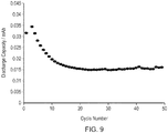
- Figure 9 shows measurements of the discharge capacity over the first 50 cycles.
- the cell demonstrated a maximum in capacity over the first 10 cycles, with the capacity stabilising after 20 cycles.
- a maximum discharge capacity of 0.077 mA h was observed in cycle 2 (corresponding to 25.4 mA h cm -2 ⁇ m -1 ). This corresponds to 83% of the theoretical capacity, based on an anode limited system.
- the substrate is heated to above about 180°C, and possibly in the range 180°C to 350°C.
- the actual temperature selected in practice will depend on various factors.
- the fairly wide range of operating temperatures available under the invention is attractive, since it facilitates matching the substrate temperature to temperatures required for other processing steps in a fabrication process.
- a temperature the same as or similar to temperatures required for other steps in a process, such as cathode deposition might be chosen to minimise adjustments.
- a temperature towards the top of the range might therefore be preferred.
- substrate temperatures at the lower end of the range may be attractive if one is interested in reducing energy usage and hence production costs.
- a temperature from the lower end of the range say from 180°C to 250°C or 275°C, or from the middle of the range, say from 200°C to 300°C, or from the top of the range, say from 250°C to 350°C, might be chosen according to circumstances.
- amorphous lithium borosilicate and nitrogen-doped lithium borosilicate has been described.
- the invention is not limited to these materials, and the process of deposition of the component elements directly onto a heated substrate is applicable to the production of other lithium containing oxide and oxynitride compounds.
- Further examples include lithium silicates and lithium borates, and other compounds containing glass-forming elements including boron, silicon, germanium, aluminium, arsenic and antimony.
- Amorphous oxides and oxynitrides can be expected to be able to be prepared by methods according to the invention, since the chemistry of binary oxides can be expected to be very similar to that of the ternary oxide/oxynitride glasses.
- the experimental results presented herein relate to thin films deposited onto titanium and platinum coated sapphire substrates and titanium and platinum coated silicon substrates.
- Other substrates may be used if preferred however.
- Other suitable examples include quartz, silica, glass, sapphire, and metallic substrates including foils, but the skilled person will understand that other substrate materials will also be suitable.
- Requirements for the substrate are that an appropriate deposition surface is provided and that it can withstand the required heating; otherwise the substrate material can be selected as desired with reference to the application to which the deposited compound is to be put.
- the embodiments of the invention are applicable equally to the deposition of the component elements directly onto the substrate surface, and onto one or more layers previously deposited or otherwise fabricated on the substrate. This is evident from the experimental results discussed above, where lithium borosilicate films were deposited onto otherwise empty heated substrates, and onto a LMO cathode layer when fabricating a sample battery.
- a substrate "depositing onto a substrate”, “co-depositing onto a substrate” and similar apply equally to "a substrate supporting one or more pre-fabricated layers”, “depositing onto a layer or layers previously fabricated on a substrate”, “co-depositing onto a layer or layers previously fabricated on a substrate” and the like.
- the invention applies equally whether or not there are any other layers intervening between the substrate and the amorphous lithium-containing oxide or oxynitride compound being deposited.
- the methods of the invention are readily adaptable to the manufacture of battery components within devices such as sensors, photovoltaic cells and integrated circuits and the like.
- the materials are not limited to use as electrolytes, and the method may be used to deposit layers of the amorphous lithium-containing oxide or oxynitride compound for any other applications. Possible examples include sensors, lithium separators, interface modifiers and ion conductors within electrochromic devices.
- amorphous lithium-containing oxide and oxynitride compounds can be deposited from vapour sources of the component elements by using an elevated substrate temperature.
- substrate temperatures up to about 100°C if the oxygen vapour source delivers molecular oxygen.
- boron and silicon vapour sources can be used to produce lithium borosilicate, plus a nitrogen vapour source to produce nitrogen-doped lithium borosilicate.
- Inclusion of a nitrogen source is more generally applicable to produce oxynitride compounds.
- Lithium silicates, oxynitride lithium silicates, lithium borates and oxynitride lithium borates may also be deposited, as can other lithium-containing oxides and oxynitrides, for example containing one or more other glass-forming elements such as germanium, aluminium, arsenic and antimony.
- the substrate material examples previously given are also applicable, as are the options of depositing directly onto a substrate or onto one or more layers already on a substrate.
- room temperature we mean temperatures in the range of about 18°C to 30°C, in particular about 25°C. However, temperatures outside this range may also be used, such as about 10°C to 20°C, about 15° C to 25°C, not higher than about 25°C, and about 20°C to 30°C. Also, somewhat higher temperatures may be used, which can be useful for integrating with other steps in a fabrication process.
- the substrate temperature may be not more than about 30°C, not more than about 50°C, not more than about 70°C or not more than about 100°C. At higher temperatures, the correct material is not formed.
- LiPt 7 Deposition of lithium borosilicate onto a substrate with a platinum layer produces crystalline LiPt 7 , for example. Examination of materials deposited at elevated temperatures using molecular oxygen by Raman spectroscopy reveals that the bands associated with the lithium borosilicate phase of interest are absent. Therefore, the upper substrate temperature for deposition is chosen with regard to avoiding the unwanted phases of lithium compounds which are prone to occur at higher temperatures and to ensure that the required phase is obtained. Typically, an upper temperature of substantially 100°C will be appropriate to avoid or minimise unwanted phases.
- the vapour source 18 will comprise a source of molecular oxygen, however.
- the heater 16 may be included to achieve a particular desired substrate temperature in line with the examples in the preceding paragraph, or may be omitted or simply not used if a general "room temperature" that is not specifically defined is deemed satisfactory.
Landscapes
- Chemical & Material Sciences (AREA)
- Engineering & Computer Science (AREA)
- Chemical Kinetics & Catalysis (AREA)
- Materials Engineering (AREA)
- Organic Chemistry (AREA)
- General Chemical & Material Sciences (AREA)
- Mechanical Engineering (AREA)
- Metallurgy (AREA)
- Manufacturing & Machinery (AREA)
- Geochemistry & Mineralogy (AREA)
- Life Sciences & Earth Sciences (AREA)
- Electrochemistry (AREA)
- Inorganic Chemistry (AREA)
- Physics & Mathematics (AREA)
- Condensed Matter Physics & Semiconductors (AREA)
- General Physics & Mathematics (AREA)
- Plasma & Fusion (AREA)
- Secondary Cells (AREA)
- Battery Electrode And Active Subsutance (AREA)
- Physical Vapour Deposition (AREA)
Applications Claiming Priority (2)
| Application Number | Priority Date | Filing Date | Title |
|---|---|---|---|
| GBGB1400274.5A GB201400274D0 (en) | 2014-01-08 | 2014-01-08 | Vapour deposition method for preparing amorphous lithium-containing compounds |
| EP15700152.0A EP3092323B1 (de) | 2014-01-08 | 2015-01-07 | Dampfabscheidungsverfahren zur herstellung von amorphen verbindungen mit lithium |
Related Parent Applications (2)
| Application Number | Title | Priority Date | Filing Date |
|---|---|---|---|
| EP15700152.0A Division-Into EP3092323B1 (de) | 2014-01-08 | 2015-01-07 | Dampfabscheidungsverfahren zur herstellung von amorphen verbindungen mit lithium |
| EP15700152.0A Division EP3092323B1 (de) | 2014-01-08 | 2015-01-07 | Dampfabscheidungsverfahren zur herstellung von amorphen verbindungen mit lithium |
Publications (1)
| Publication Number | Publication Date |
|---|---|
| EP3301203A1 true EP3301203A1 (de) | 2018-04-04 |
Family
ID=50191044
Family Applications (3)
| Application Number | Title | Priority Date | Filing Date |
|---|---|---|---|
| EP17201719.6A Withdrawn EP3301203A1 (de) | 2014-01-08 | 2015-01-07 | Dampfabscheidungsverfahren zur herstellung von amorphen lithiumverbindungen |
| EP15700152.0A Active EP3092323B1 (de) | 2014-01-08 | 2015-01-07 | Dampfabscheidungsverfahren zur herstellung von amorphen verbindungen mit lithium |
| EP17201720.4A Withdrawn EP3299489A1 (de) | 2014-01-08 | 2015-01-07 | Amorphe lithiumverbindungen |
Family Applications After (2)
| Application Number | Title | Priority Date | Filing Date |
|---|---|---|---|
| EP15700152.0A Active EP3092323B1 (de) | 2014-01-08 | 2015-01-07 | Dampfabscheidungsverfahren zur herstellung von amorphen verbindungen mit lithium |
| EP17201720.4A Withdrawn EP3299489A1 (de) | 2014-01-08 | 2015-01-07 | Amorphe lithiumverbindungen |
Country Status (11)
| Country | Link |
|---|---|
| US (1) | US10865480B2 (de) |
| EP (3) | EP3301203A1 (de) |
| JP (1) | JP6234594B2 (de) |
| KR (2) | KR102186449B1 (de) |
| CN (2) | CN105917018B (de) |
| DK (1) | DK3092323T3 (de) |
| ES (1) | ES2655288T3 (de) |
| GB (1) | GB201400274D0 (de) |
| NO (1) | NO3092323T3 (de) |
| PL (1) | PL3092323T3 (de) |
| WO (1) | WO2015104540A1 (de) |
Families Citing this family (8)
| Publication number | Priority date | Publication date | Assignee | Title |
|---|---|---|---|---|
| GB201400276D0 (en) | 2014-01-08 | 2014-02-26 | Ilika Technologies Ltd | Vapour deposition method for fabricating lithium-containing thin film layered structures |
| GB201400274D0 (en) | 2014-01-08 | 2014-02-26 | Ilika Technologies Ltd | Vapour deposition method for preparing amorphous lithium-containing compounds |
| CN109643784B (zh) * | 2016-06-15 | 2022-09-06 | 爱利卡技术有限公司 | 作为电解质和电极保护层的硼硅酸锂玻璃 |
| US11152613B2 (en) * | 2018-01-19 | 2021-10-19 | Amprius, Inc. | Stabilized, prelithiated silicon oxide particles for lithium ion battery anodes |
| GB201814039D0 (en) | 2018-08-29 | 2018-10-10 | Ilika Tech Ltd | Method |
| TW202120432A (zh) * | 2019-10-08 | 2021-06-01 | 法商液態空氣喬治斯克勞帝方法研究開發股份有限公司 | 用於沉積含鋰層、島或簇的鋰前驅體 |
| GB2589626A (en) * | 2019-12-05 | 2021-06-09 | Ilika Tech Ltd | Method |
| KR102529895B1 (ko) * | 2021-06-28 | 2023-05-08 | 주식회사 비이아이랩 | 우수한 이온 전도도를 나타내는 비정질 황화물의 제조방법 |
Citations (1)
| Publication number | Priority date | Publication date | Assignee | Title |
|---|---|---|---|---|
| GB2493022A (en) * | 2011-07-21 | 2013-01-23 | Ilika Technologies Ltd | Vapour deposition process for the preparation of a phosphate compound |
Family Cites Families (45)
| Publication number | Priority date | Publication date | Assignee | Title |
|---|---|---|---|---|
| JPS5210869A (en) | 1975-07-15 | 1977-01-27 | Toshinori Takagi | Thin film forming method |
| US4933058A (en) | 1986-01-23 | 1990-06-12 | The Gillette Company | Formation of hard coatings on cutting edges |
| US4888202A (en) | 1986-07-31 | 1989-12-19 | Nippon Telegraph And Telephone Corporation | Method of manufacturing thin compound oxide film and apparatus for manufacturing thin oxide film |
| JPS6335493A (ja) | 1986-07-31 | 1988-02-16 | Nippon Telegr & Teleph Corp <Ntt> | 複合酸化物薄膜の製造方法 |
| JPH0637351B2 (ja) | 1988-06-14 | 1994-05-18 | シャープ株式会社 | 強誘電体薄膜の製造方法 |
| JPH049748A (ja) | 1990-04-27 | 1992-01-14 | Sharp Corp | ニオブ酸リチウム薄膜の評価方法およびその製造装置 |
| JPH0784646B2 (ja) | 1990-11-20 | 1995-09-13 | 日本電気株式会社 | 誘電体薄膜の成膜方法 |
| US5338625A (en) * | 1992-07-29 | 1994-08-16 | Martin Marietta Energy Systems, Inc. | Thin film battery and method for making same |
| JPH08329944A (ja) | 1995-05-31 | 1996-12-13 | Nippondenso Co Ltd | 非水電解質二次電池用正極活物質の製造方法 |
| US5730852A (en) | 1995-09-25 | 1998-03-24 | Davis, Joseph & Negley | Preparation of cuxinygazsen (X=0-2, Y=0-2, Z=0-2, N=0-3) precursor films by electrodeposition for fabricating high efficiency solar cells |
| US6017654A (en) * | 1997-08-04 | 2000-01-25 | Carnegie Mellon University | Cathode materials for lithium-ion secondary cells |
| US6982132B1 (en) | 1997-10-15 | 2006-01-03 | Trustees Of Tufts College | Rechargeable thin film battery and method for making the same |
| US7433655B2 (en) | 2000-03-24 | 2008-10-07 | Cymbet Corporation | Battery-operated wireless-communication apparatus and method |
| US6632563B1 (en) | 2000-09-07 | 2003-10-14 | Front Edge Technology, Inc. | Thin film battery and method of manufacture |
| US6863699B1 (en) | 2000-11-03 | 2005-03-08 | Front Edge Technology, Inc. | Sputter deposition of lithium phosphorous oxynitride material |
| WO2003021706A1 (fr) * | 2001-09-03 | 2003-03-13 | Matsushita Electric Industrial Co., Ltd. | Procede de fabrication de dispositif electrochimique |
| JP2003277915A (ja) | 2002-03-26 | 2003-10-02 | Matsushita Electric Ind Co Ltd | 薄膜の製造方法及び製造装置 |
| WO2003085758A1 (en) | 2002-03-29 | 2003-10-16 | University Of Florida | Improved lithium-based rechargeable batteries |
| KR100533934B1 (ko) * | 2002-06-07 | 2005-12-06 | 강원대학교산학협력단 | 리튬 이차 전지용 고체 전해질 및 그 제조 방법 |
| WO2004093223A2 (en) | 2003-04-14 | 2004-10-28 | Massachusetts Institute Of Technology | Integrated thin film batteries on silicon integrated circuits |
| KR20040098139A (ko) * | 2003-05-13 | 2004-11-20 | 강원대학교산학협력단 | 박막 고체 전해질 및 그 제조 방법 |
| JP3677509B2 (ja) | 2003-06-27 | 2005-08-03 | 松下電器産業株式会社 | 固体電解質およびそれを用いた全固体電池 |
| US6886240B2 (en) | 2003-07-11 | 2005-05-03 | Excellatron Solid State, Llc | Apparatus for producing thin-film electrolyte |
| GB2406860A (en) | 2003-10-09 | 2005-04-13 | Univ Southampton | Vapour deposition method |
| JP2006120437A (ja) | 2004-10-21 | 2006-05-11 | Matsushita Electric Ind Co Ltd | 固体電解質電池 |
| EP1900845B1 (de) | 2004-12-08 | 2016-05-04 | Sapurast Research LLC | Abscheidung von LiCoO2 |
| US7883800B2 (en) | 2005-01-27 | 2011-02-08 | Centre National De La Recherche Scientifique | Lithium ion conducting lithium sulphur oxynitride thin film, and a process for the preparation thereof |
| WO2007004590A1 (ja) * | 2005-07-01 | 2007-01-11 | National Institute For Materials Science | 全固体リチウム電池 |
| CN101479403A (zh) | 2006-04-14 | 2009-07-08 | 硅石技术责任有限公司 | 用于制作太阳能电池的等离子沉积设备和方法 |
| KR100836256B1 (ko) | 2006-07-03 | 2008-06-10 | (주)누리셀 | 엘비더블유오계 리튬 이온 전도성 산화물 고체전해질 |
| CA2681385A1 (en) * | 2007-03-26 | 2008-10-02 | Nv Bekaert Sa | Substrate for lithium thin film battery |
| US8372250B2 (en) * | 2007-07-23 | 2013-02-12 | National Science And Technology Development Agency | Gas-timing method for depositing oxynitride films by reactive R.F. magnetron sputtering |
| US8628645B2 (en) | 2007-09-04 | 2014-01-14 | Front Edge Technology, Inc. | Manufacturing method for thin film battery |
| WO2010120813A2 (en) | 2009-04-13 | 2010-10-21 | Applied Materials, Inc. | Composite materials containing metallized carbon nanotubes and nanofibers |
| JP2011113796A (ja) * | 2009-11-26 | 2011-06-09 | Nippon Chem Ind Co Ltd | リチウム二次電池用活物質およびこれを用いたリチウム二次電池 |
| JP5360296B2 (ja) | 2010-04-13 | 2013-12-04 | トヨタ自動車株式会社 | 固体電解質材料、リチウム電池および固体電解質材料の製造方法 |
| US10770745B2 (en) | 2011-11-09 | 2020-09-08 | Sakti3, Inc. | Monolithically integrated thin-film solid state lithium battery device having multiple layers of lithium electrochemical cells |
| CN102867949B (zh) * | 2011-07-04 | 2015-09-30 | 微宏动力系统(湖州)有限公司 | 锂离子二次电池正极材料及其制备方法 |
| GB2493020B (en) | 2011-07-21 | 2014-04-23 | Ilika Technologies Ltd | Vapour deposition process for the preparation of a chemical compound |
| US9127344B2 (en) | 2011-11-08 | 2015-09-08 | Sakti3, Inc. | Thermal evaporation process for manufacture of solid state battery devices |
| JP2013151721A (ja) * | 2012-01-25 | 2013-08-08 | Toyota Motor Corp | 固体電解質膜の製造方法 |
| JP6156713B2 (ja) | 2012-03-07 | 2017-07-05 | 日産自動車株式会社 | 正極活物質、電気デバイス用正極及び電気デバイス |
| DE102012015802A1 (de) | 2012-08-10 | 2014-02-13 | Thyssenkrupp Uhde Gmbh | Verfahren zur Herstellung von Elektrolysezellen-Kontaktstreifen |
| GB201400274D0 (en) | 2014-01-08 | 2014-02-26 | Ilika Technologies Ltd | Vapour deposition method for preparing amorphous lithium-containing compounds |
| GB201400277D0 (en) | 2014-01-08 | 2014-02-26 | Ilika Technologies Ltd | Vapour deposition method for preparing crystalline lithium-containing compounds |
-
2014
- 2014-01-08 GB GBGB1400274.5A patent/GB201400274D0/en not_active Ceased
-
2015
- 2015-01-07 KR KR1020187012581A patent/KR102186449B1/ko active IP Right Grant
- 2015-01-07 JP JP2016544673A patent/JP6234594B2/ja active Active
- 2015-01-07 EP EP17201719.6A patent/EP3301203A1/de not_active Withdrawn
- 2015-01-07 EP EP15700152.0A patent/EP3092323B1/de active Active
- 2015-01-07 WO PCT/GB2015/050015 patent/WO2015104540A1/en active Application Filing
- 2015-01-07 DK DK15700152.0T patent/DK3092323T3/en active
- 2015-01-07 PL PL15700152T patent/PL3092323T3/pl unknown
- 2015-01-07 CN CN201580004001.6A patent/CN105917018B/zh active Active
- 2015-01-07 ES ES15700152.0T patent/ES2655288T3/es active Active
- 2015-01-07 KR KR1020167021181A patent/KR20160105867A/ko not_active Application Discontinuation
- 2015-01-07 EP EP17201720.4A patent/EP3299489A1/de not_active Withdrawn
- 2015-01-07 NO NO15700152A patent/NO3092323T3/no unknown
- 2015-01-07 CN CN201910005924.3A patent/CN109468595A/zh active Pending
- 2015-01-07 US US15/110,638 patent/US10865480B2/en active Active
Patent Citations (1)
| Publication number | Priority date | Publication date | Assignee | Title |
|---|---|---|---|---|
| GB2493022A (en) * | 2011-07-21 | 2013-01-23 | Ilika Technologies Ltd | Vapour deposition process for the preparation of a phosphate compound |
Also Published As
| Publication number | Publication date |
|---|---|
| JP2017504726A (ja) | 2017-02-09 |
| EP3092323A1 (de) | 2016-11-16 |
| DK3092323T3 (en) | 2018-01-15 |
| GB201400274D0 (en) | 2014-02-26 |
| WO2015104540A1 (en) | 2015-07-16 |
| CN109468595A (zh) | 2019-03-15 |
| EP3092323B1 (de) | 2017-12-27 |
| ES2655288T3 (es) | 2018-02-19 |
| US20160340784A1 (en) | 2016-11-24 |
| PL3092323T3 (pl) | 2018-04-30 |
| NO3092323T3 (de) | 2018-05-26 |
| JP6234594B2 (ja) | 2017-11-22 |
| KR20180051661A (ko) | 2018-05-16 |
| US10865480B2 (en) | 2020-12-15 |
| KR102186449B1 (ko) | 2020-12-03 |
| CN105917018B (zh) | 2019-02-19 |
| CN105917018A (zh) | 2016-08-31 |
| EP3299489A1 (de) | 2018-03-28 |
| KR20160105867A (ko) | 2016-09-07 |
Similar Documents
| Publication | Publication Date | Title |
|---|---|---|
| EP3092322B1 (de) | Dampfabscheidungsverfahren zur herstellung lithiumhaltiger dünnschichtstrukturen | |
| EP3092323B1 (de) | Dampfabscheidungsverfahren zur herstellung von amorphen verbindungen mit lithium | |
| CN105793462B (zh) | 用于制备晶态含锂化合物的气相沉积方法 | |
| CN112585294B (zh) | 用于制备无定形硼硅酸锂的方法 | |
| EP4070395B1 (de) | Verfahren |
Legal Events
| Date | Code | Title | Description |
|---|---|---|---|
| PUAI | Public reference made under article 153(3) epc to a published international application that has entered the european phase |
Free format text: ORIGINAL CODE: 0009012 |
|
| STAA | Information on the status of an ep patent application or granted ep patent |
Free format text: STATUS: THE APPLICATION HAS BEEN PUBLISHED |
|
| AC | Divisional application: reference to earlier application |
Ref document number: 3092323 Country of ref document: EP Kind code of ref document: P |
|
| AK | Designated contracting states |
Kind code of ref document: A1 Designated state(s): AL AT BE BG CH CY CZ DE DK EE ES FI FR GB GR HR HU IE IS IT LI LT LU LV MC MK MT NL NO PL PT RO RS SE SI SK SM TR |
|
| STAA | Information on the status of an ep patent application or granted ep patent |
Free format text: STATUS: REQUEST FOR EXAMINATION WAS MADE |
|
| 17P | Request for examination filed |
Effective date: 20181004 |
|
| RBV | Designated contracting states (corrected) |
Designated state(s): AL AT BE BG CH CY CZ DE DK EE ES FI FR GB GR HR HU IE IS IT LI LT LU LV MC MK MT NL NO PL PT RO RS SE SI SK SM TR |
|
| STAA | Information on the status of an ep patent application or granted ep patent |
Free format text: STATUS: REQUEST FOR EXAMINATION WAS MADE |
|
| RAP1 | Party data changed (applicant data changed or rights of an application transferred) |
Owner name: TOYOTA MOTOR CORPORATION Owner name: ILIKA TECHNOLOGIES LIMITED |
|
| STAA | Information on the status of an ep patent application or granted ep patent |
Free format text: STATUS: THE APPLICATION IS DEEMED TO BE WITHDRAWN |
|
| 18D | Application deemed to be withdrawn |
Effective date: 20210803 |