EP3299549A1 - Porte battante à déclinité de sortie - Google Patents
Porte battante à déclinité de sortie Download PDFInfo
- Publication number
- EP3299549A1 EP3299549A1 EP17191031.8A EP17191031A EP3299549A1 EP 3299549 A1 EP3299549 A1 EP 3299549A1 EP 17191031 A EP17191031 A EP 17191031A EP 3299549 A1 EP3299549 A1 EP 3299549A1
- Authority
- EP
- European Patent Office
- Prior art keywords
- locking element
- locking
- wing
- bolt
- door
- Prior art date
- Legal status (The legal status is an assumption and is not a legal conclusion. Google has not performed a legal analysis and makes no representation as to the accuracy of the status listed.)
- Withdrawn
Links
Images


Classifications
-
- E—FIXED CONSTRUCTIONS
- E05—LOCKS; KEYS; WINDOW OR DOOR FITTINGS; SAFES
- E05B—LOCKS; ACCESSORIES THEREFOR; HANDCUFFS
- E05B65/00—Locks or fastenings for special use
- E05B65/06—Locks or fastenings for special use for swing doors or windows, i.e. opening inwards and outwards
-
- E—FIXED CONSTRUCTIONS
- E05—LOCKS; KEYS; WINDOW OR DOOR FITTINGS; SAFES
- E05B—LOCKS; ACCESSORIES THEREFOR; HANDCUFFS
- E05B15/00—Other details of locks; Parts for engagement by bolts of fastening devices
- E05B15/10—Bolts of locks or night latches
- E05B15/101—Spring-retracted bolts
-
- E—FIXED CONSTRUCTIONS
- E05—LOCKS; KEYS; WINDOW OR DOOR FITTINGS; SAFES
- E05B—LOCKS; ACCESSORIES THEREFOR; HANDCUFFS
- E05B47/00—Operating or controlling locks or other fastening devices by electric or magnetic means
- E05B47/0038—Operating or controlling locks or other fastening devices by electric or magnetic means using permanent magnets
- E05B47/004—Operating or controlling locks or other fastening devices by electric or magnetic means using permanent magnets the magnets acting directly on the bolt
-
- E—FIXED CONSTRUCTIONS
- E05—LOCKS; KEYS; WINDOW OR DOOR FITTINGS; SAFES
- E05B—LOCKS; ACCESSORIES THEREFOR; HANDCUFFS
- E05B47/00—Operating or controlling locks or other fastening devices by electric or magnetic means
- E05B47/0046—Electric or magnetic means in the striker or on the frame; Operating or controlling the striker plate
- E05B47/0047—Striker rotating about an axis parallel to the wing edge
-
- E—FIXED CONSTRUCTIONS
- E05—LOCKS; KEYS; WINDOW OR DOOR FITTINGS; SAFES
- E05C—BOLTS OR FASTENING DEVICES FOR WINGS, SPECIALLY FOR DOORS OR WINDOWS
- E05C19/00—Other devices specially designed for securing wings, e.g. with suction cups
- E05C19/16—Devices holding the wing by magnetic or electromagnetic attraction
- E05C19/163—Devices holding the wing by magnetic or electromagnetic attraction a movable bolt being held in the striker by a permanent magnet
-
- E—FIXED CONSTRUCTIONS
- E05—LOCKS; KEYS; WINDOW OR DOOR FITTINGS; SAFES
- E05B—LOCKS; ACCESSORIES THEREFOR; HANDCUFFS
- E05B63/00—Locks or fastenings with special structural characteristics
- E05B63/0052—Locks mounted on the "frame" cooperating with means on the "wing"
Definitions
- the invention relates to a locking device having the features of the preamble of patent claim 1.
- a latch assembly is known with a sliding latch, which can be moved via an electric motor from an unlocking position to a locking position. By an electromagnet, the bolt is locked in the locked position. The retraction of the bolt takes place by means of a return spring.
- the object of the invention is to provide a locking device with a simple structure.
- the solution according to the invention is a stop door with a locking device.
- the stop door comprises a preferably fixedly mounted door frame and a wing movably mounted therein.
- the Verrieglungs comprises a mounted on the frame or on the wing bolt assembly and mounted on the wing or on the frame latch receiving device, wherein it is provided that the latch assembly has a movably mounted, designed as a latch or latch element and that the latch receiving means a the locking element in the Has locking position receiving latch receptacle.
- the locking device has a locking actuator, via which the locking element can be actuated in the locking direction.
- the locking device has an unlocking actuating device, via which the locking element can be actuated in the unlocking direction.
- the locking element and / or the bolt receptacle on a discharge slope which is designed such that the locking element can be acted upon by an interaction of locking element and bolt receptacle in unlocking and / or is acted upon.
- the term locking device is to be understood broadly, ie the locking element can be designed as a bolt or as a latch, preferably spring-mounted latch. In the locking position of the locking element can be a burglar-proof locking of the wing or even a locking of the wing.
- the locking device can be mounted so that the locking position is present in the closed position of the wing. However, it may also be possible to mount the locking device, in which the locking position of the locking element is present in the open position of the wing.
- Preferred applications of the locking device are applications on doors, preferably building doors.
- the door may preferably be formed with a wing pivotally mounted in a frame.
- the door can also be designed as a frame slidably mounted wing.
- the latch assembly is preferably arranged laterally on the frame or on the wing and the latch receiving device corresponding opposite preferably laterally on the wing or on the frame.
- the latch assembly is mounted in the region of the upper horizontal spar of the door frame or at the upper portion of the wing and the latch receiving means corresponding respectively to the upper portion of the wing or in the region of the upper horizontal spar of the door frame.
- the locking device is a purely mechanical lock with an outlet bevel on the locking element or on the bolt receptacle.
- very advantageous embodiments are possible as an electric lock with electrically switchable additional components.
- the scope of use of the lock on stop doors primarily refers to stop turnstiles and sliding stop doors.
- the locking element has an inlet slope, which is designed such that the locking element can be acted upon by an interaction of locking element and latch receptacle in unlocking and / or is acted upon.
- the locking element is designed as a shooting trap. It can be provided that the shooting case and / or the locking element is spring loaded.
- outlet slope of the locking element and / or the bolt receptacle is formed as a flat or curved surface.
- the inlet slope of the locking element is formed as a flat or curved surface.
- outlet slope and / or the inlet slope is / are formed as a concave surface / surfaces.
- the locking element has a spring device, by which the locking element is acted upon in the locking direction at least in the closed position of the door.
- the locking element has a spring device, by which the locking element is acted upon in the unlocking direction, at least in the open position of the door.
- the latch assembly is mounted in a lock case which is mountable in or on the frame or in or on the wing.
- a lock mechanism is mounted in the lock case, wherein the lock mechanism is designed for controlling a bolt and / or a latch.
- the locking actuator comprises an electric actuator and / or a magnetic device and / or a spring device and / or a manual or motorized wing actuator, to act on the locking element in the locking direction.
- the magnetic device of the latch receiving device is designed as a permanent magnet device and / or as an electromagnet.
- the electromagnet is reversible and / or switched off and the locking element has a permanent magnet.
- the electromagnet By reversing the polarity of the electromagnet, a locking element which is in the locked position can be transferred into the unlocked position by the electromagnet repelling the permanent engagement of the locking element.
- the latch and / or the latch is / are designed as the latch element cooperating with the magnet device of the latch receptacle device.
- the locking actuator and / or the unlocking actuator via a lock cylinder is operable / are, preferably the lock cylinder forms a part of the lock mechanism and / or is arranged in the lock case.
- the locking element interacts with the outlet bevel when the door moves in the door opening direction.
- the pivoting movement of the wing is the door opening direction.
- the door opening direction is the sliding movement, preferably horizontal sliding movement of the wing.
- the locking element for forming the unlocked position can be brought into the unlocked position without lifting the wing and / or the bolt assembly and / or the bolt receiving device. In this case, the locking element is not acted upon in a lifting movement by the outlet slope on the locking element and / or the bolt receptacle in the unlocked position.
- the outlet bevel is formed on the locking element and / or the bolt receptacle such that the locking element can be brought into the unlocking position by the pivoting movement and / or opening movement and / or during the opening process of the wing of the door.
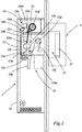
- Fig. 1 an inventive embodiment of the Verrieglungs adopted 1 mounted on a stop-hinged door.
- Fig. 2 show the structure of the Verrieglungs adopted 1 in an enlarged view.
- the stopper revolving door comprises a frame 5 and a wing 6 rotatably mounted on bands 2 about the vertical axis of the door.
- the frame-mounted locking device 1 comprises a bolt assembly 3 and a bolt receiving device 4.
- the bolt assembly 3 is laterally mounted on the frame 5 in the illustrated case.
- the Assembly is preferably carried out in the frame 5 inside.
- the bolt receiving device 4 is mounted on the wing side of the bolt assembly 3 opposite, also preferably inside.
- the bolt assembly 3 has a housing 31 with a displaceably mounted therein in the vertical direction locking element 32 which is acted upon by a first spring 33 in the unlocked position.
- the locking element 32 In the unlocked position, the locking element 32 is retracted into the housing 31 and does not project beyond the housing 31 with its free end (FIG. Fig. 2 and 2a ).
- the first spring 33 is formed in the illustrated case as a leg spring, which is rotatably mounted on a housing-fixed bearing point 33d and is supported with its first leg 33a on a housing stop and with its second leg 33b on a driver 32m of the locking element 32 from.
- an electrical switchable unlocking device 34 is arranged as a further component.
- This has an electromagnet 34m which cooperates with a bolt 32s arranged on the locking element 32.
- the electromagnet 34m comprises a coil 34s which cooperates with a pivotally mounted in the housing 31 anchor 34a.
- the armature 34a is pivotally mounted as a one-armed lever about a rotation axis 34d such that it has a release position (FIG. Fig. 2 ) and, in the case shown pivoted clockwise, blocking position ( Fig. 2a ) can take.
- a helical compression spring is arranged, the armature 34a in its blocking position ( Fig. 2a ).
- the armature 34a has a projecting stop, with which it engages in the locking position of the armature 34a, the pin 32s and thus locks the locking element 32 in its unlocked position. In the Release position of the armature 34a, the armature 34a is pivoted counterclockwise and thus out of engagement with the pin 32s.
- a locking holding device 35 is arranged in the housing 31. It comprises a first one-armed lever 35h. This first lever 35h is pivotally mounted in a bearing 32d on the locking element 32 and has a retaining bolt 35n in the center and a roller 35r at its free end (FIG. Fig. 2 and 2a ).
- a second spring 35f is arranged, which is mounted in the bearing 32d, and is supported with its first bearing arm on the locking element 32 and 35h supported with its second bearing arm on the retaining bolt 35n of the first lever.
- the first lever 35h is acted upon by the second spring 35f such that the roller 35r of the first lever 35h runs along a linear guide in the inside of the housing 31 facing away from the face ( Fig. 2b and 2c ), in the illustration in Fig. 2 the first lever 35h turns clockwise.
- the locking-holding device 35 comprises a second one-armed lever 35i, which is rotatably mounted in the housing 31 in the bearing point 33d.
- the second lever 35i has a notch 35k in the middle and a retaining plate 35p at its free end. In the illustrated case, the second lever 35i pivots counterclockwise to secure the first lever 35h (FIG. Fig.
- the lock-holding device 35 may be designed so that it can be operated in the quiescent current or working current.
- the second electromagnet 35m is supplied with voltage to the second lever 35i for securing the first lever 35h to pivot.
- the second electromagnet 35m moves the second lever 35i by energizing its coil in order to release the fuse of the first lever 35h, the second lever 35i being designed in the working current mode so that it durably secures the first lever 35h by spring action ,
- a profile cylinder can be arranged below the second electromagnet 35m in the housing 31 for an emergency unlocking, which acts via a slide or linkage on the second lever 35i for releasing the first lever 35h.
- the latch receiving device 4 mounted on the wing has a bolt receptacle 41 arranged in the baffle plate, into which the locking element engages in the locking position ( Fig. 2b and 2c ).
- a magnetic device 42 is arranged ( Fig. 2 to 2c ). This has in the case shown a permanent magnet which is designed such that it pulls in the closed position of the door, the locking element 32 into the locking position as soon as the unlocking holder 34 of the locking element 32 is released, and thus the locking element 32 is releasable ( Fig. 2b ).
- the locking holding device 35 locks the locking element 32 in the locking position (FIG. Fig. 2c ).
- the locking-holding device 35 is electrically connected accordingly.
- the prerequisite is that first the lock-holding device 35 is electrically released.
- the Entriegelungshub the locking element 32 is achieved in the illustrated embodiment, characterized in that the manual opening of the wing 6, the locking element 32 via a at the free end of the locking element 32nd trained outlet slope ( Fig. 4 to 4d ), disengages.
- the illustrated embodiment is the use of a stop-hinged door.
- the first spring 33 acts on the locking element 32 in the unlocking direction. Once the locking element 32 is due to the opening position of the blade 6 out of engagement of the magnetic device 42, takes place under the action of the first spring 33, the complete retraction of the locking element 32 in its unlocked position. In the unlocking position with fully retracted locking element 32, the locking element 32 engages with the pin 32s in engagement with the armature 34a of the unlocking holding device 34. The unlocking holding device 34 arrests the locking elements 32s (FIG. Fig. 2a ).
- the locking device 1 can also be used on a swing door.
- the locking element 32 in addition to the outlet slope and an inlet slope ( Fig. 4 ).
- the locking element 32 has at its end then a symmetrical design, so that the door leaf 6 can be rotated as a swing door leaf from the locking position both to the left and to the right.
- the locking element 32 acts in the manner of a resilient latch, which centers the door leaf 6 in the closed position, in that the locking element 32 is extended by the magnetic device 42 in the closed position.
- a resilient latch may be provided in addition to the locking element 3, so that the swing door operation can take place without the unlocking holding device 34 acting on the latch element being released. The centering of the swing door in the zero position then takes place exclusively on the resilient latch when locked in unlocked position locking element.
- the bolt assembly 3 may also be mounted in the horizontal spar of the frame 5 and the bolt receiving device 4 may be mounted on the wing side in a corresponding position.
- the locking device 1 can be installed in reverse mounting, namely the latch assembly 3 wing side and the latch receiving device 4 frame side.
- the magnetic device 41 is formed as an electro-magnetic device.
- the locking element 32 may be conceited without a run-out slope or inlet bevel.
- the locking element 32 is designed to have an outlet bevel or inlet bevel arranged at the end.
- the FIGS. 4b, 4c, 4d show such designs.
- the latch assembly 3 may preferably be arranged on the frame side of the upper spar in the running rail of the sliding leaf and the bolt receiving device 4 wing side. Again, the reverse assembly is possible.
- the direction of movement of the sliding door is in the FIG. 3 represented by an arrow.
- Fig. 4d shows an embodiment of a locking element 32, which is universally applicable to both swing doors and sliding doors by having a discharge slope and / or an inlet slope for a sliding door and an outlet slope and / or an inlet slope for a revolving door.
- the illustrated locking elements 32 with inlet slopes and chamfers are also used with conventional locking devices and conventional electric strikes. This is especially true for universal locking elements of Fig. 4d , which can be used for sliding doors as well as for revolving doors. Furthermore, this also applies to modified locking elements, which have only inlet slopes or only outlet slopes, in each case for revolving doors or sliding doors.
- These conventional locking devices may comprise a lock box mountable on or in the frame or on or in the wing, in which a preferably conventional lock mechanism is mounted.
- the lock case may be formed in such embodiments for internal mounting as a lock case of a mortise lock.
- the lock mechanism can control a bolt and / or a trap in all these different embodiments, wherein the bolt and / or the latch in the closed position of the door in the bolt receptacle extendable and / or are extended in this and is and in the open position of the door the latch and / or the latch are retracted into the lock case.
- Preferred embodiments provide that at least the bolt is retracted in the lock case.
- the latch and / or the latch can or can cooperate with the magnet device 42 arranged in the latch receptacle 41. Instead of the magnetic device 42 may also be provided a different locking device which moves the latch and / or the latch in the locked position.
- This other Locking device may be formed, for example, as an electric motor device or as a spring device or as a mechanical, manually operable handle device, preferably stored in a lock nut of the lock mechanism.
- the lock mechanism may be equipped with an electrically switchable locking device 35 and / or an electrically switchable unlocking device 34, preferably arranged in the lock case.
- the electrically switchable locking holding device 35 and / or the electrically switchable unlocking holding device 34 can also be arranged outside of the lock case in or adjacent to the latch receiving device 4.
- embodiments with locking devices are provided with preferably conventional lock mechanism, which have no electrically switchable lock-holding device 35 and no electrically switchable unlocking holder 34.
- the locking element 32 is formed with a discharge slope and / or an inlet slope and in the case of the outlet slope opening the door by pressing and / or mounting the door in cooperation with the bolt receptacle is possible without it it is necessary to actively retract the locking element via a separate actuator.
- the embodiment of the invention is used in stop doors, wherein the locking device for actuating the locking element has a locking actuator and an unlocking actuator.
- the lock actuator it is possible, instead of or in addition to the provided in the embodiments of the figures magnetic device 42 to provide another locking actuator, such as a locking element with an inlet slope, wherein the locking element preferably cooperates with a spring device which acts on the locking element in the locking direction.
- the unlocking actuator may, in addition to the formed on the locking element and / or on the latch receptacle outlet bevel also have a slider device or other mechanical transmission means of the lock mechanism, which acts on the locking element or the bolt receptacle in the sense of unlocking.
- the electrically switchable locking-holding device 35 and / or unlocking-holding device 34 and the magnetic device 42 provided in the exemplary embodiments described above are optional in the embodiments according to the invention.
Applications Claiming Priority (7)
| Application Number | Priority Date | Filing Date | Title |
|---|---|---|---|
| DE102016117955 | 2016-09-23 | ||
| DE102016118258 | 2016-09-27 | ||
| DE102016123035.9A DE102016123035A1 (de) | 2016-09-23 | 2016-11-29 | Fluchttür mit Riegel mit Auslaufschräge |
| DE102016123033.2A DE102016123033A1 (de) | 2016-09-23 | 2016-11-29 | Verriegelungseinrichtung mit magnetischer Riegelaufnahme und Auslaufschräge |
| DE102016123032.4A DE102016123032A1 (de) | 2016-09-23 | 2016-11-29 | Verriegelungseinrichtung mit magnetischer Riegelaufnahme |
| DE102016123034.0A DE102016123034A1 (de) | 2016-09-23 | 2016-11-29 | Anschlagtür mit Auslaufschräge |
| DE102017100737.7A DE102017100737A1 (de) | 2017-01-16 | 2017-01-16 | Riegel für Drehtüren und/oder Flügeltüren |
Publications (1)
| Publication Number | Publication Date |
|---|---|
| EP3299549A1 true EP3299549A1 (fr) | 2018-03-28 |
Family
ID=59858960
Family Applications (6)
| Application Number | Title | Priority Date | Filing Date |
|---|---|---|---|
| EP17191044.1A Active EP3299550B1 (fr) | 2016-09-23 | 2017-09-14 | Ouverture de porte électrique pour porte battante pourvue d'un verrou magnétique |
| EP17191036.7A Withdrawn EP3299560A1 (fr) | 2016-09-23 | 2017-09-14 | Porte d'évacuation avec verrou à déclinité de sortie |
| EP17191026.8A Active EP3299548B1 (fr) | 2016-09-23 | 2017-09-14 | Dispositif de verrouillage comprenant un logement de verrou avec aimant et déclinité de sortie |
| EP17191031.8A Withdrawn EP3299549A1 (fr) | 2016-09-23 | 2017-09-14 | Porte battante à déclinité de sortie |
| EP17191017.7A Active EP3299547B1 (fr) | 2016-09-23 | 2017-09-14 | Dispositif de verrouillage pourvu d'une gâche |
| EP17191038.3A Active EP3299555B1 (fr) | 2016-09-23 | 2017-09-14 | Verrou pour portes à tambour et/ou pour porte battantes |
Family Applications Before (3)
| Application Number | Title | Priority Date | Filing Date |
|---|---|---|---|
| EP17191044.1A Active EP3299550B1 (fr) | 2016-09-23 | 2017-09-14 | Ouverture de porte électrique pour porte battante pourvue d'un verrou magnétique |
| EP17191036.7A Withdrawn EP3299560A1 (fr) | 2016-09-23 | 2017-09-14 | Porte d'évacuation avec verrou à déclinité de sortie |
| EP17191026.8A Active EP3299548B1 (fr) | 2016-09-23 | 2017-09-14 | Dispositif de verrouillage comprenant un logement de verrou avec aimant et déclinité de sortie |
Family Applications After (2)
| Application Number | Title | Priority Date | Filing Date |
|---|---|---|---|
| EP17191017.7A Active EP3299547B1 (fr) | 2016-09-23 | 2017-09-14 | Dispositif de verrouillage pourvu d'une gâche |
| EP17191038.3A Active EP3299555B1 (fr) | 2016-09-23 | 2017-09-14 | Verrou pour portes à tambour et/ou pour porte battantes |
Country Status (2)
| Country | Link |
|---|---|
| EP (6) | EP3299550B1 (fr) |
| PL (3) | PL3299547T3 (fr) |
Families Citing this family (5)
| Publication number | Priority date | Publication date | Assignee | Title |
|---|---|---|---|---|
| CN110439383A (zh) * | 2019-09-17 | 2019-11-12 | 电子科技大学中山学院 | 一种用于防盗门的智能锁具 |
| CN110984716B (zh) * | 2019-12-19 | 2021-06-11 | 广东电网有限责任公司 | 一种侧角开门的箱式变压站 |
| DE102020205868A1 (de) * | 2020-05-11 | 2021-11-11 | Lufthansa Technik Aktiengesellschaft | Möbelschloss |
| TWI741918B (zh) * | 2020-12-22 | 2021-10-01 | 一德金屬工業股份有限公司 | 鎖閂的電動控制設備 |
| WO2024016051A1 (fr) * | 2022-07-18 | 2024-01-25 | D & D Group Pty Ltd | Améliorations apportées à des verrous pour barrières mobiles ou similaires |
Citations (6)
| Publication number | Priority date | Publication date | Assignee | Title |
|---|---|---|---|---|
| US2117715A (en) * | 1936-06-17 | 1938-05-17 | Hiram J Godfried | Lock and latch |
| US2586900A (en) * | 1949-11-02 | 1952-02-26 | Alderman Wayne | Magnetic door latch |
| US3057649A (en) * | 1961-03-07 | 1962-10-09 | Yale & Towne Mfg Co | Privacy latch |
| DE1270983B (de) * | 1962-11-14 | 1968-06-20 | Pres Pul Lock Company Ltd | Tuerverschluss mit verschiebbarer Handhabe und federbelastetem Schliessglied fuer rechts oder links aufgehende Tueren |
| US20100109349A1 (en) * | 2008-11-03 | 2010-05-06 | Joshua Todd Peabody | Rotating latch for latching and unlatching a door |
| EP2594713A2 (fr) * | 2011-11-21 | 2013-05-22 | ASSA ABLOY Sicherheitstechnik GmbH | Ouverture de porte |
Family Cites Families (20)
| Publication number | Priority date | Publication date | Assignee | Title |
|---|---|---|---|---|
| US2420743A (en) * | 1944-07-14 | 1947-05-20 | F P Smith Wire And Iron Works | Lock |
| US2695805A (en) * | 1951-07-27 | 1954-11-30 | Wheeling Steel Corp | Latch and latch bolt |
| BE667471A (fr) * | 1964-07-29 | 1900-01-01 | ||
| US3594031A (en) * | 1967-11-30 | 1971-07-20 | Jerold R Ford | Universal partition-locking system |
| GB2160251B (en) * | 1984-05-11 | 1988-01-06 | John Badger Woodman | Lockable door fastener |
| FI82287C (fi) * | 1987-04-13 | 1991-02-11 | Waertsilae Oy Ab | Doerrlaos. |
| US4875725A (en) * | 1987-12-28 | 1989-10-24 | Marks George R | Woven-wire gate lock |
| DE10312269A1 (de) * | 2003-03-19 | 2004-09-30 | Drumm Gmbh | Magneto-mechanische Schließeinrichtung |
| DE102005021840B4 (de) * | 2004-05-17 | 2023-08-17 | Assa Abloy Sicherheitstechnik Gmbh | Türöffneranordnung |
| DE102006007691B3 (de) * | 2006-02-20 | 2007-06-14 | Jul. Niederdrenk Gmbh & Co. Kg | Kompaktverriegelungseinheit, zur Verwendung an oder in Wertbehältern, für Waren- und Dienstleistungsautomaten, für Möbel, für Schiebetüren |
| DE202008003477U1 (de) * | 2008-03-11 | 2009-07-30 | Kfv Karl Fliether Gmbh & Co. Kg | Schloss |
| US7836737B2 (en) * | 2008-03-31 | 2010-11-23 | I-Tek Metal Mfg. Co., Ltd. | Lock for pivotal doors and sliding doors |
| DE202010015979U1 (de) * | 2010-11-19 | 2011-04-14 | Michael Riesel Service Gmbh | Verriegelungsanordnung |
| DE102011107472B4 (de) * | 2011-07-08 | 2014-02-20 | Assa Abloy Sicherheitstechnik Gmbh | Türöffnereinrichtung mit Permanentmagnet |
| FI124791B (fi) * | 2012-12-19 | 2015-01-30 | Abloy Oy | Ovenlukko |
| PL2935741T3 (pl) * | 2012-12-21 | 2019-10-31 | Centor Design Pty Ltd | Mechanizm ryglujący |
| US20140191515A1 (en) * | 2013-01-07 | 2014-07-10 | Edward Gorlewski | Magnetic-pin catch for cabinet or interior room door |
| US20140319850A1 (en) * | 2013-03-15 | 2014-10-30 | Securitech Group, Inc. | Magnetic door lock assembly |
| DE202014102708U1 (de) * | 2014-06-12 | 2015-09-15 | Baugruppentechnik Pollmeier Gmbh | Verriegelungssystem |
| DE202016101982U1 (de) * | 2016-04-14 | 2017-07-17 | Baugruppentechnik Pollmeier Gmbh | Schließvorrichtung |
-
2017
- 2017-09-14 PL PL17191017T patent/PL3299547T3/pl unknown
- 2017-09-14 PL PL17191038T patent/PL3299555T3/pl unknown
- 2017-09-14 EP EP17191044.1A patent/EP3299550B1/fr active Active
- 2017-09-14 EP EP17191036.7A patent/EP3299560A1/fr not_active Withdrawn
- 2017-09-14 EP EP17191026.8A patent/EP3299548B1/fr active Active
- 2017-09-14 PL PL17191044T patent/PL3299550T3/pl unknown
- 2017-09-14 EP EP17191031.8A patent/EP3299549A1/fr not_active Withdrawn
- 2017-09-14 EP EP17191017.7A patent/EP3299547B1/fr active Active
- 2017-09-14 EP EP17191038.3A patent/EP3299555B1/fr active Active
Patent Citations (6)
| Publication number | Priority date | Publication date | Assignee | Title |
|---|---|---|---|---|
| US2117715A (en) * | 1936-06-17 | 1938-05-17 | Hiram J Godfried | Lock and latch |
| US2586900A (en) * | 1949-11-02 | 1952-02-26 | Alderman Wayne | Magnetic door latch |
| US3057649A (en) * | 1961-03-07 | 1962-10-09 | Yale & Towne Mfg Co | Privacy latch |
| DE1270983B (de) * | 1962-11-14 | 1968-06-20 | Pres Pul Lock Company Ltd | Tuerverschluss mit verschiebbarer Handhabe und federbelastetem Schliessglied fuer rechts oder links aufgehende Tueren |
| US20100109349A1 (en) * | 2008-11-03 | 2010-05-06 | Joshua Todd Peabody | Rotating latch for latching and unlatching a door |
| EP2594713A2 (fr) * | 2011-11-21 | 2013-05-22 | ASSA ABLOY Sicherheitstechnik GmbH | Ouverture de porte |
Also Published As
| Publication number | Publication date |
|---|---|
| EP3299548A1 (fr) | 2018-03-28 |
| PL3299550T3 (pl) | 2021-05-31 |
| EP3299548B1 (fr) | 2021-12-01 |
| PL3299547T3 (pl) | 2021-07-05 |
| EP3299547A1 (fr) | 2018-03-28 |
| EP3299555B1 (fr) | 2020-09-02 |
| EP3299550B1 (fr) | 2020-10-28 |
| EP3299555A1 (fr) | 2018-03-28 |
| EP3299547B1 (fr) | 2020-12-30 |
| EP3299550A1 (fr) | 2018-03-28 |
| PL3299555T3 (pl) | 2021-01-25 |
| EP3299560A1 (fr) | 2018-03-28 |
Similar Documents
| Publication | Publication Date | Title |
|---|---|---|
| EP3299549A1 (fr) | Porte battante à déclinité de sortie | |
| DE602004001952T2 (de) | Elektrisches Schloss mit magnetischer Halterung des Kupplungselementes | |
| EP2096241A2 (fr) | Verrouillage supplémentaire à verrouillage automatique | |
| DE19730552C1 (de) | Einrichtung zum Entriegeln eines mechanisch selbstverriegelnden Mehrfachschlosses | |
| EP3147434A1 (fr) | Dispositif d'entrainement de verrou, en particulier d'une serrure de porte | |
| DE102015211980B4 (de) | Verschlussvorrichtung für ein ein- oder mehrteiliges Tor | |
| DE202019103639U1 (de) | Riegel für einen Türöffner mit schwimmendem Magneten | |
| EP3441549B1 (fr) | Verrouillage de porte | |
| EP2256273A2 (fr) | Crémone-serrure de verrouillage multi-points | |
| EP3208407B1 (fr) | Verrou dote d'un dispositif de securite | |
| EP0716200A1 (fr) | Dispositif de verrouillage pour portes | |
| EP1990487A2 (fr) | Serrure de porte | |
| WO2013113854A1 (fr) | Ouvre-porte et porte munie d'un ouvre-porte | |
| DE102016123034A1 (de) | Anschlagtür mit Auslaufschräge | |
| DE102015000604A1 (de) | Schlosseinrichtung für eine Tür oder ein Fenster | |
| DE102016120657B4 (de) | Vorrichtung zur Aufnahme eines Fallenriegels und Verriegelungsvorrichtung zur Verriegelung eines Türflügels | |
| EP0902140A1 (fr) | Dispositif de porte avec verrouillage de porte | |
| DE102014102041A1 (de) | Schließkantenklappe | |
| EP2683891A2 (fr) | Serrure de meuble | |
| CH715020A1 (de) | Schloss, Beschlag, Schliessblech und Schliessvorrichtung für Schiebetüren sowie Schiebetüranlage. | |
| AT16382U1 (de) | Schloss | |
| DE102016207938A1 (de) | Schloss für einen schwenkbaren Flügel | |
| EP3327237B1 (fr) | Dispositif d'entraînement électrique à courroie dentée pour portes coulissantes linéaires | |
| EP3243982B1 (fr) | Dispositif d'ouverture de porte | |
| DE7032326U (de) | Schwenkschiebetuer fuer fahrzeuge. |
Legal Events
| Date | Code | Title | Description |
|---|---|---|---|
| PUAI | Public reference made under article 153(3) epc to a published international application that has entered the european phase |
Free format text: ORIGINAL CODE: 0009012 |
|
| AK | Designated contracting states |
Kind code of ref document: A1 Designated state(s): AL AT BE BG CH CY CZ DE DK EE ES FI FR GB GR HR HU IE IS IT LI LT LU LV MC MK MT NL NO PL PT RO RS SE SI SK SM TR |
|
| AX | Request for extension of the european patent |
Extension state: BA ME |
|
| STAA | Information on the status of an ep patent application or granted ep patent |
Free format text: STATUS: THE APPLICATION HAS BEEN WITHDRAWN |
|
| 18W | Application withdrawn |
Effective date: 20180726 |