EP3299488A1 - Aufkohlungsvorrichtung und aufkohlungsverfahren - Google Patents
Aufkohlungsvorrichtung und aufkohlungsverfahren Download PDFInfo
- Publication number
- EP3299488A1 EP3299488A1 EP16796396.6A EP16796396A EP3299488A1 EP 3299488 A1 EP3299488 A1 EP 3299488A1 EP 16796396 A EP16796396 A EP 16796396A EP 3299488 A1 EP3299488 A1 EP 3299488A1
- Authority
- EP
- European Patent Office
- Prior art keywords
- organic compound
- carburization
- heating furnace
- heating
- compound vapor
- Prior art date
- Legal status (The legal status is an assumption and is not a legal conclusion. Google has not performed a legal analysis and makes no representation as to the accuracy of the status listed.)
- Pending
Links
Images




Classifications
-
- C—CHEMISTRY; METALLURGY
- C23—COATING METALLIC MATERIAL; COATING MATERIAL WITH METALLIC MATERIAL; CHEMICAL SURFACE TREATMENT; DIFFUSION TREATMENT OF METALLIC MATERIAL; COATING BY VACUUM EVAPORATION, BY SPUTTERING, BY ION IMPLANTATION OR BY CHEMICAL VAPOUR DEPOSITION, IN GENERAL; INHIBITING CORROSION OF METALLIC MATERIAL OR INCRUSTATION IN GENERAL
- C23C—COATING METALLIC MATERIAL; COATING MATERIAL WITH METALLIC MATERIAL; SURFACE TREATMENT OF METALLIC MATERIAL BY DIFFUSION INTO THE SURFACE, BY CHEMICAL CONVERSION OR SUBSTITUTION; COATING BY VACUUM EVAPORATION, BY SPUTTERING, BY ION IMPLANTATION OR BY CHEMICAL VAPOUR DEPOSITION, IN GENERAL
- C23C8/00—Solid state diffusion of only non-metal elements into metallic material surfaces; Chemical surface treatment of metallic material by reaction of the surface with a reactive gas, leaving reaction products of surface material in the coating, e.g. conversion coatings, passivation of metals
- C23C8/06—Solid state diffusion of only non-metal elements into metallic material surfaces; Chemical surface treatment of metallic material by reaction of the surface with a reactive gas, leaving reaction products of surface material in the coating, e.g. conversion coatings, passivation of metals using gases
- C23C8/08—Solid state diffusion of only non-metal elements into metallic material surfaces; Chemical surface treatment of metallic material by reaction of the surface with a reactive gas, leaving reaction products of surface material in the coating, e.g. conversion coatings, passivation of metals using gases only one element being applied
- C23C8/20—Carburising
- C23C8/22—Carburising of ferrous surfaces
-
- C—CHEMISTRY; METALLURGY
- C21—METALLURGY OF IRON
- C21D—MODIFYING THE PHYSICAL STRUCTURE OF FERROUS METALS; GENERAL DEVICES FOR HEAT TREATMENT OF FERROUS OR NON-FERROUS METALS OR ALLOYS; MAKING METAL MALLEABLE, e.g. BY DECARBURISATION OR TEMPERING
- C21D1/00—General methods or devices for heat treatment, e.g. annealing, hardening, quenching or tempering
- C21D1/06—Surface hardening
-
- C—CHEMISTRY; METALLURGY
- C21—METALLURGY OF IRON
- C21D—MODIFYING THE PHYSICAL STRUCTURE OF FERROUS METALS; GENERAL DEVICES FOR HEAT TREATMENT OF FERROUS OR NON-FERROUS METALS OR ALLOYS; MAKING METAL MALLEABLE, e.g. BY DECARBURISATION OR TEMPERING
- C21D1/00—General methods or devices for heat treatment, e.g. annealing, hardening, quenching or tempering
- C21D1/74—Methods of treatment in inert gas, controlled atmosphere, vacuum or pulverulent material
- C21D1/76—Adjusting the composition of the atmosphere
-
- C—CHEMISTRY; METALLURGY
- C21—METALLURGY OF IRON
- C21D—MODIFYING THE PHYSICAL STRUCTURE OF FERROUS METALS; GENERAL DEVICES FOR HEAT TREATMENT OF FERROUS OR NON-FERROUS METALS OR ALLOYS; MAKING METAL MALLEABLE, e.g. BY DECARBURISATION OR TEMPERING
- C21D9/00—Heat treatment, e.g. annealing, hardening, quenching or tempering, adapted for particular articles; Furnaces therefor
- C21D9/0056—Furnaces through which the charge is moved in a horizontal straight path
-
- C—CHEMISTRY; METALLURGY
- C21—METALLURGY OF IRON
- C21D—MODIFYING THE PHYSICAL STRUCTURE OF FERROUS METALS; GENERAL DEVICES FOR HEAT TREATMENT OF FERROUS OR NON-FERROUS METALS OR ALLOYS; MAKING METAL MALLEABLE, e.g. BY DECARBURISATION OR TEMPERING
- C21D9/00—Heat treatment, e.g. annealing, hardening, quenching or tempering, adapted for particular articles; Furnaces therefor
- C21D9/02—Heat treatment, e.g. annealing, hardening, quenching or tempering, adapted for particular articles; Furnaces therefor for springs
-
- C—CHEMISTRY; METALLURGY
- C23—COATING METALLIC MATERIAL; COATING MATERIAL WITH METALLIC MATERIAL; CHEMICAL SURFACE TREATMENT; DIFFUSION TREATMENT OF METALLIC MATERIAL; COATING BY VACUUM EVAPORATION, BY SPUTTERING, BY ION IMPLANTATION OR BY CHEMICAL VAPOUR DEPOSITION, IN GENERAL; INHIBITING CORROSION OF METALLIC MATERIAL OR INCRUSTATION IN GENERAL
- C23C—COATING METALLIC MATERIAL; COATING MATERIAL WITH METALLIC MATERIAL; SURFACE TREATMENT OF METALLIC MATERIAL BY DIFFUSION INTO THE SURFACE, BY CHEMICAL CONVERSION OR SUBSTITUTION; COATING BY VACUUM EVAPORATION, BY SPUTTERING, BY ION IMPLANTATION OR BY CHEMICAL VAPOUR DEPOSITION, IN GENERAL
- C23C8/00—Solid state diffusion of only non-metal elements into metallic material surfaces; Chemical surface treatment of metallic material by reaction of the surface with a reactive gas, leaving reaction products of surface material in the coating, e.g. conversion coatings, passivation of metals
- C23C8/06—Solid state diffusion of only non-metal elements into metallic material surfaces; Chemical surface treatment of metallic material by reaction of the surface with a reactive gas, leaving reaction products of surface material in the coating, e.g. conversion coatings, passivation of metals using gases
- C23C8/08—Solid state diffusion of only non-metal elements into metallic material surfaces; Chemical surface treatment of metallic material by reaction of the surface with a reactive gas, leaving reaction products of surface material in the coating, e.g. conversion coatings, passivation of metals using gases only one element being applied
- C23C8/20—Carburising
-
- C—CHEMISTRY; METALLURGY
- C23—COATING METALLIC MATERIAL; COATING MATERIAL WITH METALLIC MATERIAL; CHEMICAL SURFACE TREATMENT; DIFFUSION TREATMENT OF METALLIC MATERIAL; COATING BY VACUUM EVAPORATION, BY SPUTTERING, BY ION IMPLANTATION OR BY CHEMICAL VAPOUR DEPOSITION, IN GENERAL; INHIBITING CORROSION OF METALLIC MATERIAL OR INCRUSTATION IN GENERAL
- C23C—COATING METALLIC MATERIAL; COATING MATERIAL WITH METALLIC MATERIAL; SURFACE TREATMENT OF METALLIC MATERIAL BY DIFFUSION INTO THE SURFACE, BY CHEMICAL CONVERSION OR SUBSTITUTION; COATING BY VACUUM EVAPORATION, BY SPUTTERING, BY ION IMPLANTATION OR BY CHEMICAL VAPOUR DEPOSITION, IN GENERAL
- C23C8/00—Solid state diffusion of only non-metal elements into metallic material surfaces; Chemical surface treatment of metallic material by reaction of the surface with a reactive gas, leaving reaction products of surface material in the coating, e.g. conversion coatings, passivation of metals
- C23C8/80—After-treatment
-
- F—MECHANICAL ENGINEERING; LIGHTING; HEATING; WEAPONS; BLASTING
- F27—FURNACES; KILNS; OVENS; RETORTS
- F27B—FURNACES, KILNS, OVENS OR RETORTS IN GENERAL; OPEN SINTERING OR LIKE APPARATUS
- F27B9/00—Furnaces through which the charge is moved mechanically, e.g. of tunnel type; Similar furnaces in which the charge moves by gravity
- F27B9/04—Furnaces through which the charge is moved mechanically, e.g. of tunnel type; Similar furnaces in which the charge moves by gravity adapted for treating the charge in vacuum or special atmosphere
- F27B9/045—Furnaces with controlled atmosphere
-
- F—MECHANICAL ENGINEERING; LIGHTING; HEATING; WEAPONS; BLASTING
- F27—FURNACES; KILNS; OVENS; RETORTS
- F27B—FURNACES, KILNS, OVENS OR RETORTS IN GENERAL; OPEN SINTERING OR LIKE APPARATUS
- F27B9/00—Furnaces through which the charge is moved mechanically, e.g. of tunnel type; Similar furnaces in which the charge moves by gravity
- F27B9/30—Details, accessories or equipment specially adapted for furnaces of these types
- F27B9/3005—Details, accessories or equipment specially adapted for furnaces of these types arrangements for circulating gases
-
- F—MECHANICAL ENGINEERING; LIGHTING; HEATING; WEAPONS; BLASTING
- F27—FURNACES; KILNS; OVENS; RETORTS
- F27B—FURNACES, KILNS, OVENS OR RETORTS IN GENERAL; OPEN SINTERING OR LIKE APPARATUS
- F27B9/00—Furnaces through which the charge is moved mechanically, e.g. of tunnel type; Similar furnaces in which the charge moves by gravity
- F27B9/30—Details, accessories or equipment specially adapted for furnaces of these types
- F27B9/40—Arrangements of controlling or monitoring devices
-
- F—MECHANICAL ENGINEERING; LIGHTING; HEATING; WEAPONS; BLASTING
- F27—FURNACES; KILNS; OVENS; RETORTS
- F27D—DETAILS OR ACCESSORIES OF FURNACES, KILNS, OVENS OR RETORTS, IN SO FAR AS THEY ARE OF KINDS OCCURRING IN MORE THAN ONE KIND OF FURNACE
- F27D17/00—Arrangements for using waste heat; Arrangements for using, or disposing of, waste gases
- F27D17/10—Arrangements for using waste heat
Definitions
- the present invention relates to a carburization device and a carburization method for carburizing a steel product such as a spring member and various machine elements.
- a suspension spring is relatively heavy in weight as a unit, and is also an important component which supports the weight of the vehicle. Accordingly, the suspension spring is required to achieve the weight reduction while ensuring high reliability.
- a suspension spring manufactured by hot working is heated in the atmosphere by a temperature-raising furnace in order to perform a hot coiling process. Accordingly, occurrence of decarburization (ferrite decarburization or partial decarburization) near a surface of the spring to some extent is unavoidable.
- decarburization ferrite decarburization or partial decarburization
- the quenching hardness or the hardness after tempering is lowered, which becomes a factor of reducing the yield stress, and furthermore, reducing the fatigue strength.
- shot peening is effective. However, with the shot peening, it is not possible to produce compressive stress greater than the yield stress of a material to be treated (for example, a suspension spring). For this reason, reduction of the yield stress by the decarburization can be a cause of reduction of the effect of the shot peening.
- a carburization treatment is effective.
- conventional carburizing methods a solid carburizing method, a liquid carburizing method, a conversion furnace gas carburizing method, an injection-type gas carburizing method, a vacuum carburizing method, a plasma carburizing method, and the like, are known.
- the conversion furnace gas carburizing method, the vacuum carburizing method, and the plasma carburizing method are disclosed in, for example, JPS59-15964 B (Patent Literature 1). Many studies have been made on these carburizing methods in the past, and a control method has also been established. Accordingly, these carburizing methods are applied to various industrial products including the spring member and a gear wheel.
- Patent Literature 2 discloses a technology of performing the carburization treatment under atmospheric conditions of an open system.
- the carburization method and the carburization device of Patent Literature 2 comprise an annular heating coil which heats a material to be treated (a workpiece), and a gas nozzle which injects carburizing gas toward the heated material to be treated.
- An internal passage for circulating the carburizing gas is formed in the heating coil of Patent Literature 2. By using heat of this heating coil, the carburizing gas is heated.
- Patent Literature 3 discloses a superheated steam generator which uses a capillary feedwater function of a porous body.
- Patent Literature 2 relates to the technology of performing the carburization treatment under the atmospheric conditions of the open system.
- the material to be treated (the workpiece) and the carburizing gas are heated by using a dedicated heating coil for the carburization treatment.
- the process performed in Patent Literature 2 is a batch process which is separated from a manufacturing process of the steel product.
- Patent Literature 2 requires equipment (heating coil, etc.) dedicated to the carburization treatment, and furthermore requires electric power for heating.
- explosive carburizing gas such as propane is used, extreme caution must be taken when handling the gas.
- an object of the present invention is to provide a carburization device and a carburization method capable of performing the carburization treatment, which is carried out in a manufacturing process of a steel product such as a spring member, safely and efficiently with less items of equipment.
- a carburization device comprises a heating furnace which heats a material made of steel to a temperature at which quenching can be performed, a transfer mechanism such as a walking beam or a conveyor, an organic compound vapor generator, an organic compound vapor spraying portion, and quenching means for use in quenching the material which has been carburized.
- a heating furnace heats the material to 980 to 1000°C (i.e., an austenitizing temperature).
- the transfer mechanism moves a plurality of materials continuously or intermittently from an inlet portion to an outlet portion of the heating furnace.
- the organic compound vapor generator produces organic compound vapor by evaporating a liquid organic compound by a heat source.
- the organic compound vapor spraying portion sprays the organic compound vapor on the material which moves within the heating furnace and causes carbon in the organic compound to be adsorbed to the material, and sprays the organic compound vapor on the material again after an interval of time for diffusion of the carbon.
- a carburization treatment organic compound vapor spraying, and diffusion of carbon
- the quenching means rapidly cools the carburized material taken out of the heating furnace, and causes a hardened structure to be produced in the material.
- a large-scale conversion furnace or a dedicated carburizing furnace for producing carburizing gas becomes unnecessary, and the carburization treatment, which is carried out in a manufacturing process of a steel product such as a spring manufacturing process, can be performed safely and efficiently with less items of equipment.
- a carburization device according to a first embodiment will be described with reference to FIGS. 1 to 4 .
- FIG. 1 schematically shows the structure of a carburization device 10A implemented at a site equivalent to a laboratory.
- the carburization device 10A includes a container 12 which accommodates a material 11 made of steel, a holder 13 which holds the material 11 within the container 12, an infrared-ray converging-type heater 14 which heats the material 11, an alcohol vapor supply system 15 which is an example of an organic compound supply system, an inert gas supply system 16, an exhaust pump 18, a switching valve 19, a temperature sensor (a thermocouple) 20 which detects a temperature of the material 11, a cooling tank 21 which is to be used in quenching the material 11, etc.
- Cold water 21a is accommodated in the cooling tank 21.
- the container 12 is constituted of a quartz tube, for example, and keeps the inside of the container 12 airtight by an upper lid 12a and a bottom lid 12b which is openable and closable.
- the material 11 as a test piece is, for example, a steel rod (an oil hardened and tempered wire) having a diameter of 12 mm, and a length of 50 mm.
- the chemical components (wt%) of the oil hardened and tempered wire are C:0.41, Si:2.2, Mn:0.84, Cr:0.11, Ni:0.16, Cu:0.26, and Fe: the remainder.
- a heating furnace 25 is constituted of the container 12 and the heater 14.
- the alcohol vapor supply system 15 includes a tray 31 as a container portion, an alcohol vapor generator 32A for producing alcohol vapor, and a switching valve 36, etc.
- the tray 31 accommodates an alcohol solution 30, which is an example of a liquid organic compound.
- An example of the alcohol is ethyl alcohol (C 2 H 5 OH).
- a liquid used in a carburization treatment is not limited to alcohol, and it suffices that the liquid to be used is an organic compound having a molecular structure including at least oxygen. For example, ketone such as acetone and various acids may be used.
- An example of the alcohol vapor generator 32A includes a porous block (for example, a firebrick) 33, which is an example of a porous body having an open-celled foam structure, and an electric heater arranged within a flow hole of the porous block 33. At least a part of the porous block 33 is immersed in the alcohol solution 30 accommodated in the tray 31. The alcohol solution is penetrated and diffused in the porous block 33, and alcohol vapor obtained as a result of vaporization in the porous block 33 is fed into a mixing pipeline 35.
- a porous block for example, a firebrick
- an electric heater arranged within a flow hole of the porous block 33.
- At least a part of the porous block 33 is immersed in the alcohol solution 30 accommodated in the tray 31.
- the alcohol solution is penetrated and diffused in the porous block 33, and alcohol vapor obtained as a result of vaporization in the porous block 33 is fed into a mixing pipeline 35.
- heat intake means for taking heat of the heating furnace 25 into the porous block 33 is adopted.
- An example of the heat intake means is a pipe 34 for taking in the heat of the heating furnace 25. By connecting the pipe 34 to the porous block 33, the porous block 33 is heated by utilizing the heat of the heating furnace 25.
- Alcohol vapor is produced by the alcohol vapor generator 32A. As the alcohol vapor is supplied to the container 12 through the mixing pipeline 35, the interior of the container 12 is filled with the alcohol vapor. As the high-temperature material 11 is brought into contact with the alcohol vapor inside the container 12, carbon in the alcohol adsorbs to the material 11.
- the inert gas supply system 16 includes a gas supply source 40 and an opening and closing valve 41.
- Inert gas such as argon is accommodated in the gas supply source 40.
- argon gas in the gas supply source 40 is supplied to the mixing pipeline 35 through the opening and closing valve 41 and a pipeline 42.
- the alcohol vapor can be diluted by the inert gas such as argon gas.
- the material 11 in the container 12 is heated to approximately 1000°C by the heater 14.
- alcohol vapor is produced by the alcohol vapor generator 32A.
- the alcohol vapor is supplied to the container 12 through the mixing pipeline 35.
- carbon in the alcohol adsorbs to the material. After that, by switching the switching valve 36, supply of the alcohol vapor from the alcohol vapor generator 32A is stopped.
- the alcohol vapor inside the container 12 is discharged by the exhaust pump 18, and the container 12 is filled with argon gas supplied from the gas supply source 40.
- an interval of a certain period of time (for example, 53 seconds) is taken. By doing so, carbon is diffused in the material 11, and soot is also prevented from adhering to a surface of the material 11.
- a carburization treatment for the first time i.e., alcohol vapor spraying and diffusion of carbon for the first time
- the carburization treatment for the second time onward is carried out.
- the above-described carburization treatment (alcohol vapor spraying and diffusion of carbon) is repeated a plurality of times. Consequently, a carburized layer having a carbon concentration of 0.4 to 1.2% by weight is formed at a depth of 1 mm or so from the surface of the material 11.
- the bottom lid 12b of the container 12 is opened.
- the material 11 which is at a high temperature (i.e., a temperature at which quenching can be performed) taken out of the container 12 is put into the cold water 21a of the cooling tank 21 and is cooled rapidly, thereby performing the quenching.
- a hardened structure (martensite) is formed in at least a surface layer portion of the material 11.
- FIG. 2 shows the relationship between a distance from a surface of the material and Vickers hardness for each of the cases where the number of repetitions (n) of the carburization treatment is 5, 10, 15, and 20.
- FIG. 3 shows the relationship between the number of repetitions (n) of the carburization treatment and the carburized depth.
- FIG. 4 shows the relationship between a distance from a surface of the material and the carbon concentration for each of the cases where the number of repetitions (n) of the carburization treatment is 5, 10, 15, and 20. From FIG. 4 , it can be understood that in the surface layer portion which is a portion at a point of approximately 1 mm from the surface, the greater the number of carburization treatments is, the more the carbon concentration is increased, and the deeper the place where the carbon concentration can be increased is.
- a carburization device according to a second embodiment will be described with reference to FIGS. 5 and 6 .
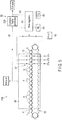
- FIG. 5 schematically shows a carburization device 10B which performs carburization at a site equivalent to a factory in a spring manufacturing process.
- the carburization device 10B comprises a heating furnace 50, a transfer mechanism 55, an alcohol vapor supply system 56, an alcohol vapor spraying portion 57, a quenching tank 58 as the quenching means, etc.
- the heating furnace 50 functions as a heat treatment furnace which heats a material 11 made of spring steel.
- the transfer mechanism 55 moves a plurality of materials 11 from an inlet portion 51 of the heating furnace 50 toward an outlet portion 52 of the same.
- a quenching liquid such as water or oil is accommodated in the quenching tank 58.
- the heating furnace 50 forms a flame by burning inflammable gas such as city gas. By this flame, the material 11 is heated to a temperature (for example, 980°C) at which the quenching can be performed.
- the heating furnace 50 heats the material 11 made of steel to an austenitizing temperature. More specifically, the heating furnace 50 is a temperature-raising furnace (a heat treatment furnace), and heats the material 11 under atmospheric conditions of an open system.
- the type of heating of the heating furnace 50 is not limited to an open-type gas heating furnace.
- a heating furnace of indirect heating comprising a radiant tube may be employed.
- the inside of the furnace may be heated by using a radiant heat generated by a radiant tube burner using a radiant tube.
- An example of the transfer mechanism 55 is an intermittent movement type device which makes a progress and a pause alternately such as a walking beam.
- the plurality of materials 11 are moved from the inlet portion 51 of the heating furnace 50 toward the outlet portion 52 of the same by the transfer mechanism 55 in a direction indicated by arrow F in FIG. 5 .
- a conveyor which is moved endlessly continuously may be adopted.
- the alcohol vapor supply system 56 comprises an alcohol vapor generator 32B, an exhaust heat intake tube 61, an alcohol vapor supply tube 62, a flow regulator 63, an inert gas supply portion 64, and a carbon dioxide gas supply portion 65, which are schematically shown in FIG. 6 .
- the exhaust heat intake tube 61 which functions as exhaust heat intake means uses part of the heat generated by the heating furnace 50 as a heat source of the alcohol vapor generator 32B.
- the flow regulator 63 is arranged between the alcohol vapor generator 32B and the heating furnace 50. Alcohol vapor is supplied toward the alcohol vapor spraying portion 57 from the alcohol vapor generator 32B. An amount of the alcohol vapor is regulated by the flow regulator 63. If necessary, inert gas such as nitrogen is supplied from the inert gas supply portion 64. Alternatively, carbon dioxide may be supplied from the carbon dioxide gas supply portion 65.
- An example of the alcohol vapor generator 32B shown in FIG. 6 comprises a tray 70, a porous block 71, and a flow hole 72 formed in the porous block 71.
- the tray 70 is an example of a container portion which accommodates an alcohol solution 30.
- the porous block 71 is an example of a porous body having an open-celled foam structure which is impregnated with the alcohol solution 30 in the tray 70.
- Part of high-temperature gas produced in the heating furnace 50 flows into the flow hole 72 through the exhaust heat intake tube 61.
- the heat of the high-temperature gas vaporizes alcohol (ethyl alcohol) in the porous block 71.
- Alcohol gas obtained by the vaporization is supplied to the alcohol vapor spraying portion 57 from the alcohol vapor supply tube 62.
- the exhaust heat intake tube 61 in this case functions as the heating means for heating at least a part of an inner surface of the flow hole 72.
- the alcohol vapor spraying portion 57 includes a plurality of nozzles 57a, 57b, and 57n. These nozzles 57a, 57b, and 57n spray the alcohol vapor on the materials 11 which move inside the heating furnace 50 stepwise. Accordingly, the nozzles 57a, 57b, and 57n surround the materials 11, which are moved inside the heating furnace 50 by the transfer mechanism 55, near the outlet portion 52. Moreover, these nozzles 57a, 57b, and 57n are arranged at intervals in a direction of movement of the materials 11, in other words, are arranged at separate stages.
- the nozzle 57a at a first stage is arranged on an upstream side in the direction of movement of the materials 11 near the outlet portion 52 of the heating furnace 50.
- the nozzle 57b at a second stage is arranged on a more downstream side in the direction of movement of the materials 11 as compared to the nozzle 57a at the first stage.
- the nozzle 57n at an N-th stage (a third stage onward) is arranged on a more downstream side in the direction of movement of the materials 11 as compared to the nozzle 57b at the second stage.
- the alcohol vapor produced by the alcohol vapor generator 32B is ejected toward the materials 11 from the respective nozzles 57a, 57b, and 57n. Accordingly, highly-concentrated alcohol vapor exists around the materials 11.
- An interval section i.e., a section for diffusion of carbon in which a concentration of the alcohol vapor is substantially extremely low is formed between the adjacent nozzles of the nozzles 57a, 57b, and 57n.
- FIG. 7 is a cross-sectional view which schematically shows another example of the alcohol vapor generator.
- An alcohol vapor generator 32C shown in FIG. 7 includes a high-temperature gas passage 80 within the flow hole 72 formed in the porous block 71.
- the exhaust heat intake tube 61 is connected to the high-temperature gas passage 80.
- Part of high-temperature gas in the heating furnace 50 flows in the high-temperature gas passage 80.
- the high-temperature gas passage 80 functions as heating means for heating at least a part of an inner surface of the flow hole 72.
- the alcohol vapor generator may use an external heat source without using the heat of the heating furnace.
- an electric heater can be used as a heat source such as in an alcohol vapor generation system according to the first embodiment.
- FIG. 8 shows an example of a manufacturing process of manufacturing a steel product such as a spring member.
- step ST1 heating step
- step ST2 carburization step
- a carburization treatment is performed by using the carburization device 10B.
- FIG. 9 shows the details of step ST2 (carburization step) of FIG. 8 .
- step ST2 the material 11 which moves within the heating furnace 50 is moved to a position opposed to the nozzle 57a ( FIG. 5 ) at the first stage.
- the nozzle 57a at the first stage sprays the alcohol vapor on the material 11.
- vapor spraying step ST10 which is the first vapor spraying step
- carbon in the alcohol adsorbs to the material 11.
- diffusion step ST11 which is the first diffusion step
- the carburizing action progresses by the Boudouard reaction (2CO ⁇ [C] +CO 2 ), etc.
- the material 11 is moved to a position opposed to the nozzle 57b ( FIG. 5 ) at the second stage.
- the alcohol vapor is sprayed on the material 11 again by the nozzle 57b at the second stage.
- vapor spraying step ST12 which is the second vapor spraying step, is carried out, and carbon in the alcohol adsorbs to the material 11.
- diffusion step ST13 which is the second diffusion step, the carburizing action progresses again by the Boudouard reaction etc., and the carbon concentration near the surface of the material 11 is increased.
- the material 11 is moved to a position opposed to the nozzle 57n ( FIG. 5 ) at the N-th stage.
- the alcohol vapor is sprayed on the material 11 again by the nozzle 57n at the N-th stage.
- vapor spraying step ST14 which is the N-th vapor spraying step
- carbon in the alcohol adsorbs to the material 11.
- diffusion step ST15 which is the N-th diffusion step
- the carburizing action progresses again by the Boudouard reaction etc., and the carbon concentration near the surface of the material 11 is further increased.
- the carburization treatment (alcohol vapor spraying and diffusion) is repeated a plurality of times (N times) within the heating furnace 50.
- Carburization is performed by the carburization step (step ST2), and the material 11 kept at a high temperature is carried outside the heating furnace 50 from the outlet portion 52 of the heating furnace 50.
- step ST3 of FIG. 8 the material 11 is thrown into the quenching tank 58.
- a hardened structure is formed in at least a surface layer portion of the material 11.
- step ST4 of FIG. 8 a tempering heat treatment is performed. Since the material 11 has gone through the carburization step, the material 11 has sufficient hardness after the tempering. Further, in step ST5 (forming step), the material 11 is formed into a predetermined shape (for example, the shape of a coil spring) by plastic working, etc. In step ST6, shot peening is performed, and compressive residual stress is applied to the surface of the material 11. An aftertreatment such as setting and coating is performed as necessary. In step ST7, product inspection is performed and the spring member is completed.
- FIG. 10 shows an example of a manufacturing process in forming the steel product by hot working (at a recrystallization temperature or higher).
- step ST1 heating step
- step ST5 forming step of FIG. 10
- the material 11 is formed by hot working.
- step ST2 a carburization step corresponding to step ST2 is carried out after the hot forming. More specifically, in step ST2, the carburization treatment is performed in the heating furnace 50 by the carburization device 10B ( FIG. 5 ). Also in this case, alcohol vapor spraying and carbon diffusion are repeated a plurality of times (N times), as shown in FIG. 9 , thereby performing the carburization treatment stepwise.
- step ST3 and ST4 heat treatments such as quenching and tempering
- steps ST6, ST7 shots peening, inspection (steps ST6, ST7), and the like, are carried out.
- step ST2 (carburization step) is carried out after step ST5 (forming step). However, step ST2 (carburization step) may be carried out simultaneously with step ST1 (heating step), or after step ST1 (heating step).
- a carburization method for the steel product according to the present embodiment includes the following steps:
- a conversion furnace for producing carburizing gas or a dedicated carburizing furnace is unnecessary. Accordingly, the carburization treatment can be performed with less items of equipment, and the treatment is safe since ethanol vapor is used as the carburizing gas. Also, the carburization treatment can be performed substantially simultaneously with the heat treatment in a heat treatment furnace (heating furnace) which constitutes a part of a manufacturing line that continuously produces a workpiece (a steel product). Accordingly, a steel product having a carburized layer can be produced efficiently.
- the form such as the specific structure and arrangement of elements which constitute the carburization device according to the present invention i.e., elements including the heating furnace, the transfer mechanism, the alcohol vapor generator, the exhaust heat intake means, the alcohol vapor spraying portion, and the quenching means may be embodied in various forms if necessary.
- the alcohol used in carburization is not limited to ethyl alcohol, and may be any as long as it is a compound having a structure in which a hydrogen atom of a carbon hydride is substituted with a hydroxyl group and it is a substance that can vaporize, in short.
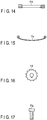
- FIGS. 11 to 17 schematically illustrate first to seventh examples of the spring member, which is a steel product.
- FIG. 11 shows a helical spring 11a such as a coil spring.
- FIG. 12 shows a vehicle stabilizer 11b.
- FIG. 13 shows a disc spring 11c,
- FIG. 14 shows a torsion bar 11d, and
- FIG. 15 shows a leaf spring 11e.
- the carburization device and the carburization method of the present invention may be applied to a machine element such as a gear wheel 11f shown in FIG. 16 or a screw member 11g shown in FIG. 17 , for example, apart from the above spring members.
- the carburization device and the carburization method of the present invention may be applied to industrial products other than the above.
- the present invention can be applied to any steel product in which a carburized layer having a high carbon concentration is desired to be formed on a surface layer portion by the carburization.
- 10A, 10B ⁇ Carburization device 11 ⁇ Material, 11a-11g ⁇ Steel product, 30 ⁇ Alcohol solution (one example of liquid organic compound), 31 ⁇ Tray (container portion), 32A, 32B, 32C ⁇ Alcohol vapor generator, 50 ⁇ Heating furnace, 51 ⁇ Inlet portion, 52 ⁇ Outlet portion, 55 ⁇ Transfer mechanism, 56 ⁇ Alcohol vapor supply system, 57 ⁇ Alcohol vapor spraying portion, 57a, 57b, 57n ⁇ Nozzle, 58 ⁇ Quenching tank (quenching means), 61 ⁇ Exhaust heat intake tube (exhaust heat intake means), 62 ⁇ Alcohol vapor supply tube, 70 ⁇ Tray (container portion), 71 ⁇ Porous block (porous body), 72 ⁇ Flow hole, 80 ⁇ High-temperature gas passage
Landscapes
- Chemical & Material Sciences (AREA)
- Engineering & Computer Science (AREA)
- Mechanical Engineering (AREA)
- Materials Engineering (AREA)
- Metallurgy (AREA)
- Organic Chemistry (AREA)
- General Engineering & Computer Science (AREA)
- Crystallography & Structural Chemistry (AREA)
- Thermal Sciences (AREA)
- Physics & Mathematics (AREA)
- Chemical Kinetics & Catalysis (AREA)
- Environmental & Geological Engineering (AREA)
- Solid-Phase Diffusion Into Metallic Material Surfaces (AREA)
- Heat Treatment Of Articles (AREA)
- Tunnel Furnaces (AREA)
Applications Claiming Priority (2)
| Application Number | Priority Date | Filing Date | Title |
|---|---|---|---|
| JP2015101781A JP6488191B2 (ja) | 2015-05-19 | 2015-05-19 | 浸炭装置と浸炭方法 |
| PCT/JP2016/064183 WO2016186003A1 (ja) | 2015-05-19 | 2016-05-12 | 浸炭装置と浸炭方法 |
Publications (2)
| Publication Number | Publication Date |
|---|---|
| EP3299488A1 true EP3299488A1 (de) | 2018-03-28 |
| EP3299488A4 EP3299488A4 (de) | 2018-11-07 |
Family
ID=57319907
Family Applications (1)
| Application Number | Title | Priority Date | Filing Date |
|---|---|---|---|
| EP16796396.6A Pending EP3299488A4 (de) | 2015-05-19 | 2016-05-12 | Aufkohlungsvorrichtung und aufkohlungsverfahren |
Country Status (7)
| Country | Link |
|---|---|
| US (1) | US10584408B2 (de) |
| EP (1) | EP3299488A4 (de) |
| JP (1) | JP6488191B2 (de) |
| KR (1) | KR102004078B1 (de) |
| CN (1) | CN107614735B (de) |
| MX (1) | MX2017014770A (de) |
| WO (1) | WO2016186003A1 (de) |
Families Citing this family (4)
| Publication number | Priority date | Publication date | Assignee | Title |
|---|---|---|---|---|
| JP6630817B2 (ja) * | 2016-03-30 | 2020-01-15 | 日本発條株式会社 | 中空ばね部材及び中空ばね部材製造方法 |
| CN109487201B (zh) * | 2019-01-09 | 2021-02-19 | 嘉善龙焱热处理厂(普通合伙) | 一种金属工件渗碳炉 |
| CN113862608B (zh) * | 2021-09-26 | 2024-03-01 | 南京高速齿轮制造有限公司 | 一种渗碳介质喷射装置 |
| KR102494316B1 (ko) | 2021-09-30 | 2023-02-06 | 한국생산기술연구원 | 침탄원료의 저감 및 입계산화의 저감을 위한 가스침탄방법 |
Family Cites Families (17)
| Publication number | Priority date | Publication date | Assignee | Title |
|---|---|---|---|---|
| JPS4923258A (de) | 1972-06-26 | 1974-03-01 | ||
| US4059122A (en) | 1973-02-10 | 1977-11-22 | Glory Kogyo Kabushiki Kaisha | Coin classifying and counting machine |
| JPS49105736A (de) * | 1973-02-13 | 1974-10-07 | ||
| JPS51117934A (en) * | 1975-04-09 | 1976-10-16 | Fujikoshi Kk | Droppinggtype gas carburizing furnace |
| JPS5915964B2 (ja) | 1977-10-14 | 1984-04-12 | オリエンタルエンヂニアリング株式会社 | 鋼の熱処理方法 |
| JPS5915964A (ja) | 1982-07-19 | 1984-01-27 | Canon Inc | 画像表示装置 |
| CH686072A5 (de) * | 1992-06-19 | 1995-12-29 | Alusuisse Lonza Services Ag | Sprayanlage zum Kuhlen von Profilen. |
| JP3792369B2 (ja) * | 1997-09-19 | 2006-07-05 | ジャパン・エア・ガシズ株式会社 | 熱処理用雰囲気発生装置 |
| FR2777910B1 (fr) * | 1998-04-27 | 2000-08-25 | Air Liquide | Procede de regulation du potentiel carbone d'une atmosphere de traitement thermique et procede de traitement thermique mettant en oeuvre une telle regulation |
| JP4923258B2 (ja) * | 2006-02-14 | 2012-04-25 | 国立大学法人横浜国立大学 | 過熱水蒸気発生装置及び過熱水蒸気発生方法 |
| JP2008057039A (ja) * | 2006-08-02 | 2008-03-13 | Ntn Corp | 浸炭方法、鋼製品、および熱処理設備 |
| CN101338358B (zh) * | 2007-07-05 | 2010-06-02 | 刘正贤 | 提升马氏体不锈钢表面硬度的方法 |
| DE102007047074A1 (de) * | 2007-10-01 | 2009-04-02 | Robert Bosch Gmbh | Verfahren zur Aufkohlung von Werkstücken sowie Verwendung |
| CN100503878C (zh) * | 2007-12-29 | 2009-06-24 | 江苏丰东热技术股份有限公司 | 减少内氧化的渗碳工艺 |
| JP5799483B2 (ja) | 2009-07-23 | 2015-10-28 | トヨタ自動車株式会社 | 浸炭方法および浸炭装置 |
| JP5361098B1 (ja) | 2012-09-14 | 2013-12-04 | 日本発條株式会社 | 圧縮コイルばねおよびその製造方法 |
| JP6661594B2 (ja) | 2017-12-12 | 2020-03-11 | ファナック株式会社 | モジュール及び電子機器 |
-
2015
- 2015-05-19 JP JP2015101781A patent/JP6488191B2/ja active Active
-
2016
- 2016-05-12 CN CN201680027822.6A patent/CN107614735B/zh active Active
- 2016-05-12 EP EP16796396.6A patent/EP3299488A4/de active Pending
- 2016-05-12 WO PCT/JP2016/064183 patent/WO2016186003A1/ja not_active Ceased
- 2016-05-12 MX MX2017014770A patent/MX2017014770A/es unknown
- 2016-05-12 KR KR1020177033209A patent/KR102004078B1/ko active Active
-
2017
- 2017-11-16 US US15/814,892 patent/US10584408B2/en active Active
Also Published As
| Publication number | Publication date |
|---|---|
| EP3299488A4 (de) | 2018-11-07 |
| CN107614735B (zh) | 2021-04-23 |
| JP6488191B2 (ja) | 2019-03-20 |
| MX2017014770A (es) | 2018-02-13 |
| JP2016216774A (ja) | 2016-12-22 |
| KR20170138499A (ko) | 2017-12-15 |
| WO2016186003A1 (ja) | 2016-11-24 |
| KR102004078B1 (ko) | 2019-07-25 |
| US20180080113A1 (en) | 2018-03-22 |
| US10584408B2 (en) | 2020-03-10 |
| CN107614735A (zh) | 2018-01-19 |
Similar Documents
| Publication | Publication Date | Title |
|---|---|---|
| US10584408B2 (en) | Carburization device and carburization method | |
| JP5826748B2 (ja) | 浸炭、窒化および/または炭窒化に先立って、鉄または非鉄金属不動態の製品を活性化する方法 | |
| Ichiki et al. | Nitriding of steel surface by spraying pulsed-arc plasma jet under atmospheric pressure | |
| CN107109616A (zh) | 在较低压强和较高温度下钢零件的碳氮共渗方法和设备 | |
| JP2004270025A (ja) | 特に懸架装置構成要素製造のための高周波焼入れ装置 | |
| JP5572251B1 (ja) | 鉄鋼部材の表面硬化処理法及び表面硬化処理装置 | |
| FI3175005T3 (fi) | Menetelmä erikoislujan teräskappaleen tuottamiseksi | |
| CN103361594A (zh) | 一种钢制加工件表面渗碳氮化处理方法 | |
| JP6592588B2 (ja) | 中空スタビライザ製造方法及び中空スタビライザ製造装置 | |
| KR20170052457A (ko) | 저온 진공침탄방법 | |
| CN117355619A (zh) | 用于在贝氏体生产中进行真空和油等温淬火的方法和系统 | |
| CN111868292B (zh) | 真空渗碳处理方法以及渗碳部件的制造方法 | |
| CN108779546B (zh) | 中空弹簧构件及其制造方法 | |
| CN107683344A (zh) | 钛材料的表面氮化处理方法 | |
| JP7253886B2 (ja) | 鉄合金及び他の金属からなる被加工物の低圧浸炭(lpc)の方法 | |
| CN106661649B (zh) | 具有高强度和优异的化学转化处理性的热处理钢制品及其制造方法 | |
| Jegou et al. | Activation of surfaces prior to gaseous nitriding of a 3wt.% Cr carbon iron-based alloy | |
| RU2354712C1 (ru) | Способ создания охлаждающей среды с регулируемыми теплофизическими свойствами | |
| CN110079652A (zh) | 用于制造钢构件的方法 | |
| PIT | A NEW LOW-PRESSURE CARBURIZING SOLUTION | |
| JPS6233754A (ja) | ガス浸炭熱処理方法 | |
| RU2402631C1 (ru) | Способ газовой термической и химико-термической обработки изделий в "кипящем слое" наноструктурированного катализатора | |
| JPH04350115A (ja) | 同一油槽を使用する焼入れ、焼戻し方法 | |
| Tikhonov et al. | Intensification of carburizing (carbonitriding) in mass production | |
| Aliev et al. | Carburizing and nitrocarburizing of automotive parts in a fluidized bed. |
Legal Events
| Date | Code | Title | Description |
|---|---|---|---|
| STAA | Information on the status of an ep patent application or granted ep patent |
Free format text: STATUS: THE INTERNATIONAL PUBLICATION HAS BEEN MADE |
|
| PUAI | Public reference made under article 153(3) epc to a published international application that has entered the european phase |
Free format text: ORIGINAL CODE: 0009012 |
|
| STAA | Information on the status of an ep patent application or granted ep patent |
Free format text: STATUS: REQUEST FOR EXAMINATION WAS MADE |
|
| 17P | Request for examination filed |
Effective date: 20171107 |
|
| AK | Designated contracting states |
Kind code of ref document: A1 Designated state(s): AL AT BE BG CH CY CZ DE DK EE ES FI FR GB GR HR HU IE IS IT LI LT LU LV MC MK MT NL NO PL PT RO RS SE SI SK SM TR |
|
| AX | Request for extension of the european patent |
Extension state: BA ME |
|
| DAV | Request for validation of the european patent (deleted) | ||
| DAX | Request for extension of the european patent (deleted) | ||
| A4 | Supplementary search report drawn up and despatched |
Effective date: 20181005 |
|
| RIC1 | Information provided on ipc code assigned before grant |
Ipc: C23C 8/22 20060101AFI20180929BHEP Ipc: F27B 9/04 20060101ALI20180929BHEP Ipc: C23C 8/80 20060101ALI20180929BHEP Ipc: F27B 9/40 20060101ALI20180929BHEP Ipc: C21D 1/06 20060101ALI20180929BHEP Ipc: C21D 9/02 20060101ALI20180929BHEP Ipc: C23C 8/20 20060101ALI20180929BHEP Ipc: F27B 9/30 20060101ALI20180929BHEP Ipc: F27D 17/00 20060101ALI20180929BHEP |
|
| STAA | Information on the status of an ep patent application or granted ep patent |
Free format text: STATUS: EXAMINATION IS IN PROGRESS |
|
| 17Q | First examination report despatched |
Effective date: 20201207 |