EP3299409B1 - Method and device for modifying resin - Google Patents
Method and device for modifying resin Download PDFInfo
- Publication number
- EP3299409B1 EP3299409B1 EP16796489.9A EP16796489A EP3299409B1 EP 3299409 B1 EP3299409 B1 EP 3299409B1 EP 16796489 A EP16796489 A EP 16796489A EP 3299409 B1 EP3299409 B1 EP 3299409B1
- Authority
- EP
- European Patent Office
- Prior art keywords
- resin
- gas
- modification
- resin film
- ozone
- Prior art date
- Legal status (The legal status is an assumption and is not a legal conclusion. Google has not performed a legal analysis and makes no representation as to the accuracy of the status listed.)
- Active
Links
- 229920005989 resin Polymers 0.000 title claims description 177
- 239000011347 resin Substances 0.000 title claims description 177
- 238000000034 method Methods 0.000 title claims description 13
- 239000007789 gas Substances 0.000 claims description 150
- CBENFWSGALASAD-UHFFFAOYSA-N Ozone Chemical compound [O-][O+]=O CBENFWSGALASAD-UHFFFAOYSA-N 0.000 claims description 128
- 229930195735 unsaturated hydrocarbon Natural products 0.000 claims description 69
- 238000002715 modification method Methods 0.000 claims description 29
- 238000004804 winding Methods 0.000 claims description 11
- 239000012495 reaction gas Substances 0.000 claims description 3
- 230000004048 modification Effects 0.000 description 123
- 238000012986 modification Methods 0.000 description 123
- 238000011282 treatment Methods 0.000 description 74
- 230000000694 effects Effects 0.000 description 21
- 229920000098 polyolefin Polymers 0.000 description 15
- 208000028659 discharge Diseases 0.000 description 14
- 238000007599 discharging Methods 0.000 description 10
- -1 polypropylene Polymers 0.000 description 10
- XLYOFNOQVPJJNP-UHFFFAOYSA-N water Substances O XLYOFNOQVPJJNP-UHFFFAOYSA-N 0.000 description 10
- 238000006243 chemical reaction Methods 0.000 description 8
- 238000010438 heat treatment Methods 0.000 description 7
- 239000007788 liquid Substances 0.000 description 7
- 238000005192 partition Methods 0.000 description 7
- 229920001721 polyimide Polymers 0.000 description 6
- 229920006324 polyoxymethylene Polymers 0.000 description 6
- VGGSQFUCUMXWEO-UHFFFAOYSA-N Ethene Chemical compound C=C VGGSQFUCUMXWEO-UHFFFAOYSA-N 0.000 description 5
- 239000005977 Ethylene Substances 0.000 description 5
- 230000006872 improvement Effects 0.000 description 5
- 239000000463 material Substances 0.000 description 5
- 239000001301 oxygen Substances 0.000 description 5
- 229910052760 oxygen Inorganic materials 0.000 description 5
- 238000009832 plasma treatment Methods 0.000 description 5
- KAKZBPTYRLMSJV-UHFFFAOYSA-N Butadiene Chemical compound C=CC=C KAKZBPTYRLMSJV-UHFFFAOYSA-N 0.000 description 4
- 239000004696 Poly ether ether ketone Substances 0.000 description 4
- 239000004698 Polyethylene Substances 0.000 description 4
- 239000004734 Polyphenylene sulfide Substances 0.000 description 4
- 229920001328 Polyvinylidene chloride Polymers 0.000 description 4
- PPBRXRYQALVLMV-UHFFFAOYSA-N Styrene Chemical compound C=CC1=CC=CC=C1 PPBRXRYQALVLMV-UHFFFAOYSA-N 0.000 description 4
- 230000008034 disappearance Effects 0.000 description 4
- 239000011261 inert gas Substances 0.000 description 4
- 230000007246 mechanism Effects 0.000 description 4
- 229920002530 polyetherether ketone Polymers 0.000 description 4
- 239000005020 polyethylene terephthalate Substances 0.000 description 4
- 229920000139 polyethylene terephthalate Polymers 0.000 description 4
- 229920000069 polyphenylene sulfide Polymers 0.000 description 4
- 239000000758 substrate Substances 0.000 description 4
- 238000010894 electron beam technology Methods 0.000 description 3
- 125000002887 hydroxy group Chemical group [H]O* 0.000 description 3
- 238000009413 insulation Methods 0.000 description 3
- 239000000543 intermediate Substances 0.000 description 3
- 229920003207 poly(ethylene-2,6-naphthalate) Polymers 0.000 description 3
- 239000011112 polyethylene naphthalate Substances 0.000 description 3
- 238000003860 storage Methods 0.000 description 3
- DHKHKXVYLBGOIT-UHFFFAOYSA-N 1,1-Diethoxyethane Chemical compound CCOC(C)OCC DHKHKXVYLBGOIT-UHFFFAOYSA-N 0.000 description 2
- NLHHRLWOUZZQLW-UHFFFAOYSA-N Acrylonitrile Chemical compound C=CC#N NLHHRLWOUZZQLW-UHFFFAOYSA-N 0.000 description 2
- 239000004215 Carbon black (E152) Substances 0.000 description 2
- 229930040373 Paraformaldehyde Natural products 0.000 description 2
- 239000004952 Polyamide Substances 0.000 description 2
- 239000004642 Polyimide Substances 0.000 description 2
- 239000004743 Polypropylene Substances 0.000 description 2
- 239000011354 acetal resin Substances 0.000 description 2
- 229920000122 acrylonitrile butadiene styrene Polymers 0.000 description 2
- 150000001336 alkenes Chemical class 0.000 description 2
- 239000004760 aramid Substances 0.000 description 2
- 229920003235 aromatic polyamide Polymers 0.000 description 2
- 230000008859 change Effects 0.000 description 2
- 239000007795 chemical reaction product Substances 0.000 description 2
- 238000005229 chemical vapour deposition Methods 0.000 description 2
- 238000007334 copolymerization reaction Methods 0.000 description 2
- 238000003851 corona treatment Methods 0.000 description 2
- 238000000354 decomposition reaction Methods 0.000 description 2
- 238000013461 design Methods 0.000 description 2
- 238000004508 fractional distillation Methods 0.000 description 2
- 230000006870 function Effects 0.000 description 2
- 229930195733 hydrocarbon Natural products 0.000 description 2
- 150000002430 hydrocarbons Chemical class 0.000 description 2
- 230000001678 irradiating effect Effects 0.000 description 2
- 238000003475 lamination Methods 0.000 description 2
- 238000002156 mixing Methods 0.000 description 2
- 238000006011 modification reaction Methods 0.000 description 2
- 230000001590 oxidative effect Effects 0.000 description 2
- WURFKUQACINBSI-UHFFFAOYSA-M ozonide Chemical compound [O]O[O-] WURFKUQACINBSI-UHFFFAOYSA-M 0.000 description 2
- 229920011301 perfluoro alkoxyl alkane Polymers 0.000 description 2
- 229920013653 perfluoroalkoxyethylene Polymers 0.000 description 2
- 230000002093 peripheral effect Effects 0.000 description 2
- 229920002647 polyamide Polymers 0.000 description 2
- 239000004417 polycarbonate Substances 0.000 description 2
- 229910021420 polycrystalline silicon Inorganic materials 0.000 description 2
- 229920000573 polyethylene Polymers 0.000 description 2
- 229920001155 polypropylene Polymers 0.000 description 2
- 229920005591 polysilicon Polymers 0.000 description 2
- 238000007789 sealing Methods 0.000 description 2
- 239000000126 substance Substances 0.000 description 2
- 238000004381 surface treatment Methods 0.000 description 2
- 239000000057 synthetic resin Substances 0.000 description 2
- 229920003002 synthetic resin Polymers 0.000 description 2
- IJGRMHOSHXDMSA-UHFFFAOYSA-N Atomic nitrogen Chemical compound N#N IJGRMHOSHXDMSA-UHFFFAOYSA-N 0.000 description 1
- 239000004721 Polyphenylene oxide Substances 0.000 description 1
- 150000001345 alkine derivatives Chemical class 0.000 description 1
- HSFWRNGVRCDJHI-UHFFFAOYSA-N alpha-acetylene Natural products C#C HSFWRNGVRCDJHI-UHFFFAOYSA-N 0.000 description 1
- 230000004888 barrier function Effects 0.000 description 1
- 230000015572 biosynthetic process Effects 0.000 description 1
- 229910052799 carbon Inorganic materials 0.000 description 1
- 125000004432 carbon atom Chemical group C* 0.000 description 1
- 150000001732 carboxylic acid derivatives Chemical class 0.000 description 1
- 230000015556 catabolic process Effects 0.000 description 1
- 239000011248 coating agent Substances 0.000 description 1
- 238000000576 coating method Methods 0.000 description 1
- 230000002301 combined effect Effects 0.000 description 1
- 238000007796 conventional method Methods 0.000 description 1
- 230000001419 dependent effect Effects 0.000 description 1
- 230000006866 deterioration Effects 0.000 description 1
- 229910001873 dinitrogen Inorganic materials 0.000 description 1
- 238000001035 drying Methods 0.000 description 1
- 238000005516 engineering process Methods 0.000 description 1
- 125000002534 ethynyl group Chemical group [H]C#C* 0.000 description 1
- 238000011156 evaluation Methods 0.000 description 1
- 230000005281 excited state Effects 0.000 description 1
- 239000004744 fabric Substances 0.000 description 1
- 239000000835 fiber Substances 0.000 description 1
- 238000007429 general method Methods 0.000 description 1
- 230000009477 glass transition Effects 0.000 description 1
- 231100000206 health hazard Toxicity 0.000 description 1
- 230000020169 heat generation Effects 0.000 description 1
- 230000002209 hydrophobic effect Effects 0.000 description 1
- 150000002576 ketones Chemical class 0.000 description 1
- 239000004973 liquid crystal related substance Substances 0.000 description 1
- 230000007774 longterm Effects 0.000 description 1
- 238000004519 manufacturing process Methods 0.000 description 1
- 150000002825 nitriles Chemical class 0.000 description 1
- JRZJOMJEPLMPRA-UHFFFAOYSA-N olefin Natural products CCCCCCCC=C JRZJOMJEPLMPRA-UHFFFAOYSA-N 0.000 description 1
- 239000005416 organic matter Substances 0.000 description 1
- 229920003023 plastic Polymers 0.000 description 1
- 239000004033 plastic Substances 0.000 description 1
- 229920000515 polycarbonate Polymers 0.000 description 1
- 229920006267 polyester film Polymers 0.000 description 1
- 229920001225 polyester resin Polymers 0.000 description 1
- 239000004645 polyester resin Substances 0.000 description 1
- 229920000570 polyether Polymers 0.000 description 1
- 229920005672 polyolefin resin Polymers 0.000 description 1
- 230000008569 process Effects 0.000 description 1
- 238000012545 processing Methods 0.000 description 1
- 239000000047 product Substances 0.000 description 1
- 230000009257 reactivity Effects 0.000 description 1
- 230000009467 reduction Effects 0.000 description 1
- 238000006722 reduction reaction Methods 0.000 description 1
- 239000005871 repellent Substances 0.000 description 1
- 238000005096 rolling process Methods 0.000 description 1
- 238000000638 solvent extraction Methods 0.000 description 1
- 238000004544 sputter deposition Methods 0.000 description 1
- 125000000383 tetramethylene group Chemical group [H]C([H])([*:1])C([H])([H])C([H])([H])C([H])([H])[*:2] 0.000 description 1
- 238000009834 vaporization Methods 0.000 description 1
- 230000008016 vaporization Effects 0.000 description 1
Images


Classifications
-
- C—CHEMISTRY; METALLURGY
- C08—ORGANIC MACROMOLECULAR COMPOUNDS; THEIR PREPARATION OR CHEMICAL WORKING-UP; COMPOSITIONS BASED THEREON
- C08J—WORKING-UP; GENERAL PROCESSES OF COMPOUNDING; AFTER-TREATMENT NOT COVERED BY SUBCLASSES C08B, C08C, C08F, C08G or C08H
- C08J7/00—Chemical treatment or coating of shaped articles made of macromolecular substances
- C08J7/12—Chemical modification
-
- C—CHEMISTRY; METALLURGY
- C01—INORGANIC CHEMISTRY
- C01B—NON-METALLIC ELEMENTS; COMPOUNDS THEREOF; METALLOIDS OR COMPOUNDS THEREOF NOT COVERED BY SUBCLASS C01C
- C01B13/00—Oxygen; Ozone; Oxides or hydroxides in general
- C01B13/10—Preparation of ozone
-
- C—CHEMISTRY; METALLURGY
- C01—INORGANIC CHEMISTRY
- C01B—NON-METALLIC ELEMENTS; COMPOUNDS THEREOF; METALLOIDS OR COMPOUNDS THEREOF NOT COVERED BY SUBCLASS C01C
- C01B13/00—Oxygen; Ozone; Oxides or hydroxides in general
- C01B13/10—Preparation of ozone
- C01B13/11—Preparation of ozone by electric discharge
-
- C—CHEMISTRY; METALLURGY
- C08—ORGANIC MACROMOLECULAR COMPOUNDS; THEIR PREPARATION OR CHEMICAL WORKING-UP; COMPOSITIONS BASED THEREON
- C08C—TREATMENT OR CHEMICAL MODIFICATION OF RUBBERS
- C08C19/00—Chemical modification of rubber
- C08C19/04—Oxidation
-
- C—CHEMISTRY; METALLURGY
- C08—ORGANIC MACROMOLECULAR COMPOUNDS; THEIR PREPARATION OR CHEMICAL WORKING-UP; COMPOSITIONS BASED THEREON
- C08F—MACROMOLECULAR COMPOUNDS OBTAINED BY REACTIONS ONLY INVOLVING CARBON-TO-CARBON UNSATURATED BONDS
- C08F8/00—Chemical modification by after-treatment
- C08F8/06—Oxidation
-
- C—CHEMISTRY; METALLURGY
- C08—ORGANIC MACROMOLECULAR COMPOUNDS; THEIR PREPARATION OR CHEMICAL WORKING-UP; COMPOSITIONS BASED THEREON
- C08J—WORKING-UP; GENERAL PROCESSES OF COMPOUNDING; AFTER-TREATMENT NOT COVERED BY SUBCLASSES C08B, C08C, C08F, C08G or C08H
- C08J2323/00—Characterised by the use of homopolymers or copolymers of unsaturated aliphatic hydrocarbons having only one carbon-to-carbon double bond; Derivatives of such polymers
- C08J2323/02—Characterised by the use of homopolymers or copolymers of unsaturated aliphatic hydrocarbons having only one carbon-to-carbon double bond; Derivatives of such polymers not modified by chemical after treatment
- C08J2323/04—Homopolymers or copolymers of ethene
- C08J2323/06—Polyethene
Definitions
- the present invention relates to a resin modification method for modifying the surface of resin and to a modification device.
- Films formed of plastic resins have superior characteristics and are used in many industries. Typical films are exemplified by polyester films, aramid films, olefin films, polypropylene films, PPS (polyphenylene sulfide) films, and PET (polyethylene terephthalate) films.
- PE polyethylene
- POM polyoxymethylene or acetal resin
- PEEK polyether ether ketone
- ABS resin acrylonitrile, butadiene and styrene copolymerization synthetic resin
- PA polyamide
- PFA ethylene tetrafluoride-perfluoroalkoxyethylene copolymer
- PI polyimide
- PVD polyvinyl dichloride
- the films are made to have high functions not only by film material, but also by technologies such as high functionality of the film layer structure (bulk control), multilayer lamination, surface control, etc. Furthermore, flexible devices that function even on products subjected to deformation are produced by forming electronic devices, wirings, etc. on these films. Thus, the possibility of their application is expanding, such as wearable computer, digital signage capable of being attached to and installed in various places, etc.
- the film surface modification such as in Patent Publication 1.
- the surface modification is to modify a hydrophobic (water-repellent) film surface to have hydrophilicity, for the purpose of barrier property improvement, durability improvement, wettability improvement (adhesion improvement), etc. That is, the film surface is modified by destroying the molecular structure of the film material surface with a certain means and adding hydrophilic OH groups, O groups, etc.
- film surface modification means there are (1) a physical modification method such as corona discharge, plasma treatment, sputtering treatment, etc., (2) a modification method by UV light irradiation or electron beam irradiation, etc., (3) a modification method by a reactive gas such as ozone, (4) a wet method by a liquid chemical, ozone water, etc., and the like.
- the modification method (2) by UV light irradiation or electron beam irradiation, etc. is not suitable as a method for modifying only the film surface in view of the film having a property to easily transmit these UV lights and electron beams.
- the modification method (3) by a reactive gas has a risk that a sufficient surface modification effect is not obtained.
- ozone gas as a typical reactive gas
- oxygen radicals as the reaction active species contributing to the modification reaction cannot sufficiently be supplied to the film surface.
- UV light e.g., Patent Publication 2
- oxygen radicals generated by UV light irradiation are oxygen radicals in excited state and extremely high in reactivity. Therefore, its control is difficult.
- the modification effect is lost as time passes.
- a film having a small contact angle of a water drop by a hydrophilic treatment the contact angle of a water drop returns to a state close to that prior to the treatment in several days. Therefore, it is believed that a long-term storage of the film is difficult.
- the hydrophilic treatment is conducted two times immediately after the film production and prior to the film use in order to maintain hydrophilicity of the film.
- Patent Publication 10 discloses a method of forming an oxide film comprising forming an oxide film on a film formation substrate by oxidizing the element to be oxidized, i.e. oxidizing the coating film into the oxide film by ozone gas and an unsaturated hydrocarbon gas.
- Patent Publication 11 discloses a method of forming a gate insulating film, comprising irradiating a substrate having polysilicon formed thereon with light in an ultraviolet region and supplying ozone gas to form a gate insulating film on the polysilicon.
- Patent Publication 12 discloses an ozone processing apparatus that supplies various ozone gases and Patent Publication 13 discloses a method of forming an oxide film on the surface of the substrate by a CVD method (chemical vapour deposition).
- CVD method chemical vapour deposition
- a resin modification method of the present invention for achieving the above object, there is provided a resin modification method by providing an ozone gas having an ozone concentration of 50 volume % or more and an unsaturated hydrocarbon gas to a resin to make a surface of the resin hydrophilic, wherein a resin, which has previously been wound onto a winding shaft, is wound onto another winding shaft, and providing the ozone gas and the unsaturated hydrocarbon gas to the resin moving between these winding shafts.
- a total pressure of a mixed gas of the ozone gas and the unsaturated hydrocarbon gas is from 50 Pa to 500 Pa.
- the ozone gas and the unsaturated hydrocarbon gas are provided to the resin for one minute or less.
- a modification apparatus for achieving the above object, it comprises a treatment furnace having a supply roll onto which a resin is previously wound and a take-up roll onto which the resin supplied from the supply roll is wound; an ozone supply device that supplies an ozone gas to the resin moving from the supply roll to the take-up roll; and an unsaturated hydrocarbon supply device that supplies an unsaturated hydrocarbon gas to the resin moving from the supply roll to the take-up roll.
- a shower head which is provided to be opposed to the resin moving from the supply roll to the take-up roll, and the ozone gas and the unsaturated hydrocarbon gas are supplied from the shower head.
- a pair of shower heads which is provided in the treatment furnace, and the resin is moved between the pair of shower heads.
- a conveying roll which is provided between the supply roll and the take-up roll, and the ozone gas and the unsaturated hydrocarbon gas are supplied to the resin moving on the conveying roll.
- a shower head that is curved to conform to a curved surface of the conveying roll, and the ozone gas and the unsaturated hydrocarbon gas are supplied from the shower head.
- the shower head which has a discharge hole for discharging the ozone gas and a discharge hole for discharging the unsaturated hydrocarbon gas, which are alternate in a direction of the moving of the resin.
- a part of the shower head which is provided with a discharge hole for discharging the ozone gas and a discharge hole for discharging the unsaturated hydrocarbon gas.
- a feeding speed of the resin is defined as v (cm/s) and that in a feeding direction of the resin a width of a region in the shower head, in which region the discharge hole for discharging the ozone gas or the discharge hole for discharging the unsaturated hydrocarbon gas is formed, is defined as L (cm), L/v is 3 seconds or longer and 60 seconds or shorter.
- the treatment furnace which is provided with a partition plate that divides the treatment furnace into a modification treatment space in which the ozone gas and the unsaturated hydrocarbon gas are reacted with the resin and a storage space in which the supply roll and the take-up roll are provided.
- an inert gas which is allowed to flow in the storage space.
- the ozone supply device which has a plurality of ozone storing vessels that store liquid ozone.
- a resin modification method is to conduct a modification of the resin surface by supplying a high-concentration ozone gas having an ozone concentration of 50 volume % or more and an unsaturated hydrocarbon gas to the resin. It is known that ozone reacts in general with an unsaturated hydrocarbon and a resulting unstable intermediate such as ozonide decomposes into ketone, carboxylic acid, etc.
- a modification apparatus which is one to conduct a modification of the resin surface by a high-concentration ozone gas and an unsaturated hydrocarbon gas by using a method (a so-called Roll to Roll method) in which, while winding a resin film roll onto another roll, the modification treatment is conducted in the middle of winding.
- a hydrophilic treatment (modification treatment) of the resin surface is conducted by a reaction product between a high-concentration ozone gas and an unsaturated hydrocarbon gas, and thus the modification treatment is conducted mainly in the vicinity of a mixing region between the high-concentration ozone gas and the unsaturated hydrocarbon gas.
- a resin subjected to the modification treatment there is used a resin that can be formed into film, sheet, cloth or fiber.
- a resin formed by a material such as polyester resin, aramid resin, olefin resin, polypropylene resin, PPS (polyphenylene sulfide) resin, or PET (polyethylene terephthalate), which is used singly or in combination.
- the modification treatment is conducted on a resin made of a material such as PE (polyethylene), POM (polyoxymethylene or acetal resin), PEEK (polyether ether ketone), ABS resin (acrylonitrile, butadiene and styrene copolymerization synthetic resin), PA (polyamide), PFA (ethylene tetrafluoride-perfluoroalkoxyethylene copolymer), PI (polyimide), PVD (polyvinyl dichloride), PC (polycarbonate), PEN (1) (polyether nitrile), and PEN (2) (polyethylene naphthalate).
- PE polyethylene
- POM polyoxymethylene or acetal resin
- PEEK polyether ether ketone
- ABS resin acrylonitrile, butadiene and styrene copolymerization synthetic resin
- PA polyamide
- PFA ethylene tetrafluoride-perfluoroalkoxyethylene copolymer
- PI poly
- the high-concentration ozone gas is an ozone gas having an ozone concentration of 20 volume % or greater, preferably 50 volume % or greater, more preferably 90 volume % or greater.
- Ozone gas produced by a general method e.g., silent discharge method
- As an apparatus for producing such high-concentration ozone gas for example, there is Pure Ozone Generator (MPOG-MP) made by Meidensha Corporation. In MPOG-MP, it is possible to supply a high-concentration ozone gas having an ozone concentration of from 20 volume % to 100 volume %.
- MPOG-MP Pure Ozone Generator
- the unsaturated hydrocarbon gas is, for example, a gas containing an unsaturated hydrocarbon like a double-bond containing hydrocarbon (alkene), such as ethylene, or a triple-bond containing hydrocarbon (alkyne), such as acetylene.
- an unsaturated hydrocarbon like a double-bond containing hydrocarbon (alkene), such as ethylene, or a triple-bond containing hydrocarbon (alkyne), such as acetylene.
- alkene such as ethylene
- alkyne such as acetylene
- a low-molecular-weight one for example, one having a carbon atom number of about 10 or less
- the modification treatment time is, for example, 1 minute or less, more preferably from 3 seconds to 20 seconds. If the treatment time is longer than 1 minute, the resin (film) itself may become clouded or the resin surface may become rough. The treatment may be conducted for 1 minute or longer in case that the resin does not become clouded or the resin surface does not become rough.
- the modification treatment temperature is low.
- the resin may be heated to the extent that the resin is not deformed or deteriorated.
- the resin is heated at a temperature that is not higher than its glass transition temperature and subjected to the modification treatment.
- the total pressure of the mixed gas of the high-concentration ozone gas and the unsaturated hydrocarbon gas is controlled to the level of from several pascals to several thousand pascals, more preferably to the range of from middle vacuum to low vacuum of 50 Pa to 500 Pa. This is to prevent the reaction from becoming uncontrollable as a result of abrupt decomposition reactions of unstable intermediates, such as ozonide, that are generated by the reaction of the high-concentration ozone and the unsaturated hydrocarbon or during its process.
- Fig. 1 shows an outline of a resin modification apparatus 1 according to the first embodiment of the present invention.
- the modification apparatus 1 according to the first embodiment has a chamber 2, an unsaturated hydrocarbon supply device 3, an ozone generating device 4, and a vacuum pump 5.
- the chamber 2 is a vacuum container (treatment furnace) for conducting the modification treatment of a resin film 6.
- the supply roll 7 is a winding shaft onto which the resin film 6 is previously wound
- the take-up roll 8 is a winding roll onto which the resin film 6 supplied from the supply roll 7 is wound.
- conveying rolls 9 Between the supply roll 7 and the take-up roll 8, there are provided conveying rolls 9, and the resin film 6 supplied from the supply roll 7 moves onto the conveying rolls 9 and are wound onto the take-up roll 8.
- a shower head 10 to be opposed to the surface of the resin film 6 moving between the supply roll 7 and the take-up roll 8.
- the shower head 10 supplies the high-concentration ozone gas and the unsaturated hydrocarbon gas to the surface of the resin film 6.
- the unsaturated hydrocarbon supply device 3 and the ozone generating device 4 are connected through pipes.
- the shower head 10 is formed on its surface opposed to the surface of the resin surface 6, with discharge holes 10a for discharging the unsaturated gas and discharge holes 10b for discharging the high-concentration ozone gas, such that the high-concentration ozone gas and the unsaturated hydrocarbon gas are supplied to the surface of the resin film 6.
- the high-concentration ozone gas and the unsaturated hydrocarbon gas are pulled in the moving direction of the resin film 6, thereby accelerating mixing of these gases.
- the mixed gas of the high-concentration ozone gas and the unsaturated hydrocarbon gas efficiently act on the resin film 6.
- the shower head 10 is partially formed with the discharge holes 10a and the discharge holes 10b, it is possible to make the surface of the resin film 6 partially hydrophilic.
- the shower head 10 is provided at a position away from the surface of the resin film 6 by several millimeters to several centimeters (e.g., 2 mm to 3 cm). It is possible to more uniformly treat the surface of the resin film 6 by arranging the shower head 10 such that the gas (the high-concentration ozone gas and the unsaturated hydrocarbon gas) discharge surface of the shower head 10 becomes parallel with the treated surface of the resin film 6. Furthermore, it is possible to make the surface of the resin film 6 more uniformly hydrophilic by adjusting error of the distance between the gas discharge surface of the shower head 10 and the surface of the resin film 6 to 1-2 mm.
- the unsaturated hydrocarbon supply device 3 supplies the unsaturated hydrocarbon gas to the chamber 2.
- the unsaturated hydrocarbon supply device 3 has a cylinder filled with the unsaturated hydrocarbon gas and a valve for conducting supply of the unsaturated hydrocarbon gas filled therein and its stop.
- the ozone generating device 4 generates the high-concentration ozone gas to be supplied to the chamber 2. That is, the ozone generating device 4 is an ozone supply device for supplying the high-concentration ozone to the chamber 2.
- the ozone generating device 4 has a low-concentration ozone generating section for generating a low-concentration ozone gas by silent discharge, etc. and a high-concentration ozone generating section for generating a high-concentration ozone gas by a liquid-producing fractional distillation of the low-concentration ozone.
- the ozone generating device 4 is equipped with a plurality of ozone storing vessels for storing liquid ozone, when generating the high-concentration ozone from one ozone storing vessel, it becomes possible to make another ozone storing vessel stand by in a condition of being capable of supplying the high-concentration ozone or to make it receive liquid ozone. This makes it possible to continuously supply the high-concentration ozone gas from the ozone generating device 4.
- ozone generating device 4 there is known, for example, Pure Ozone Generator (MPOG-HM1A1) made by Meidensha Corporation.
- the vacuum pump 5 is a pump for discharging the gas of the chamber 2 to the outside by conducting a depressurization adjustment of the chamber 2.
- the modification effect can be obtained by making the vacuum pump 5 conduct exhaustion such that pressure of the chamber 2 becomes several thousand pascals or lower (specifically about 1,000 Pa or lower) during the supply of the gases from the unsaturated hydrocarbon supply device 3 and the ozone generating device 4.
- the vacuum pump 5 is connected to a side part of the chamber 2 through a pipe.
- an ozone-proof pump e.g., dry pump
- a gas discharging pipe, to which the vacuum pump is connected is provided with an ozone decomposition device (not shown in the drawings).
- the modification apparatus 1 it is optional to provide the modification apparatus 1 with a heating mechanism (e.g., infrared heater) for heating the resin film 6 during the modification of the surface of the resin film 6.
- the heating mechanism is provided, for example, to be opposed to the bottom surface (a resin surface on the opposite side of the resin surface opposed to the shower head 10). It is preferable to provide the heating mechanism 6 at a position away from the resin film 6 by several millimeters, because damage of the resin film 6 is suppressed. The effect of the hydrophilic treatment of the resin film 6 is improved by heating the resin film 6.
- a supply roll 7 onto which a polyolefin film had been wound was set in the chamber 2. Then, the inside of the chamber 2 was evacuated to several pascals or less by the vacuum pump 5.
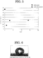
- the contact angle of a water drop on the surface of the polyolefin film had a tendency to increase after the modification treatment as time elapsed.
- the contact angle of a water drop on the surface of the polyolefin film was smaller than that of the untreated polyolefin film even after more than one month passed from conducting the treatment, and the effect of the modification treatment was maintained for more than one month.
- the modification method of the resin film 6 according to the first embodiment of the present invention it is possible to conduct a surface modification treatment that is small in these wettability effect disappearance after the modification treatment.
- a surface modification treatment that is small in these wettability effect disappearance after the modification treatment.
- the hydrophilic treatment of a resin film by corona discharge, plasma treatment, etc. it was necessary sometimes to conduct the modification treatment at the time of making the resin film and at the time immediately before the use in various applications such as bonding, thereby making the operation cumbersome.
- the modification method of the resin film 6 according to the first embodiment of the present invention it is possible to maintain the effect of the modification treatment. Therefore, it becomes possible to store the resin film 6 according to loads of various treatments. Furthermore, it is possible to separate from each other an apparatus for conducting the hydrophilic treatment and an apparatus for conducting a treatment such as bonding, thereby improving flexibility of the facility arrangement.
- the high-concentration ozone gas and the unsaturated hydrocarbon gas are supplied to the surface of the resin film 6.
- the high-concentration ozone gas and the unsaturated hydrocarbon gas are supplied to the surface of the resin film 6.
- ozone concentration of the high-concentration ozone gas to 50 volume % or greater (more preferably 90 volume % or greater)
- the modification method of the resin film 6 according to the first embodiment of the present invention is for the purpose of the surface modification of the resin film 6. Therefore, the modification treatment of the resin film 6 is conducted in a condition (time or temperature) in which the surface of the resin film 6 does not become rough and in which the resin film 6 is not deformed or deteriorated. As a result, the surface modification reaction of the resin film 6 based on the reaction between the high-concentration ozone and the unsaturated hydrocarbon can be stopped at a reaction until a stage where the molecular structure on the film surface is destroyed and O groups or OH groups are added. For example, if the modification time of the resin film 6 is adjusted to 1 minute or shorter, it is possible to suppress the generation of roughness, etc.
- this width L is defined as the distance between the discharge holes 10a (or discharge holes 10b) formed at both ends in the shower head 10 in the supply direction of the resin film 6.
- the width of the shower head 10 in the supply direction of the resin film 6 can be regarded as the width L.
- a discharge treatment such as corona discharge or plasma treatment, which is frequently used as a physical modification method, is conducted under atmospheric pressure to generate ozone. If the generated ozone leaks to the surroundings, it causes health hazard to the operator. Besides, it affects parts (parts for vibration reduction, sealing and insulation uses) made of rubber, resin, etc. in the apparatus, peripheral devices, etc. to deteriorate these parts. In particular, in case that the parts made of rubber, resin, etc. are used in electric insulation application, there is a risk that it causes insulation failure, electrical leakage, etc. of the apparatus or the devices.
- the modification apparatus 1 in contrast with this, it is possible to have no leakage of ozone gas to the outside and thereby to prevent the influence of ozone against the peripheral devices by reacting the high-concentration ozone gas and the unsaturated hydrocarbon gas with the resin film 6 under reduced pressure in the vacuum container (i.e., chamber 2).
- a modification apparatus 11 of the resin film 6 according to the second embodiment of the present invention is explained in detail.
- the modification apparatus 11 according to the second embodiment is different from the modification apparatus 1 according the first embodiment in that a pair of shower heads 10, 12 has been provided in the chamber 2. Therefore, structures similar to those of the modification apparatus 1 according to the first embodiment are designated by the same symbols, and different structures are explained in detail.
- the modification apparatus 11 has a chamber 2, an unsaturated hydrocarbon supply device 3, an ozone generating device 4, and a vacuum pump 5.
- the shower heads 10, 12 are provided to be opposed to the surfaces of the resin film 6 moving between the supply roll 7 and the take-up roll 8.
- the shower head 10 is provided to be opposed to one surface of the resin film 6.
- the surface of the shower head 10 opposed to the resin film 6 is formed with the unsaturated hydrocarbon discharge holes 10a and the high-concentration ozone gas discharge holes 10b as shown in Fig. 2 (or Fig. 3 ).
- the unsaturated hydrocarbon supply device 3 and the ozone generating device 4 are connected through pipes.
- the shower head 12 is provided to be opposed to the other surface of the resin film 6. Similar to the shower head 10, the surface of the shower head 12 opposed to the resin film 6 is formed with the unsaturated hydrocarbon discharge holes and the high-concentration ozone gas discharge holes as shown in Fig. 2 (or Fig. 3 ). To the shower head 12, the unsaturated hydrocarbon supply device 3 and the ozone generating device 4 are connected through pipes. Similar to the shower head 10, the shower head 12 is provided at a position away from the surface of the resin film 6.
- the supply roll 7 onto which the resin film 6 has been wound is set in the chamber 2, and the chamber is evacuated, for example, to several pascals or less. While the resin film 6 supplied from the supply roll 7 is wound onto the take-up roll 8, the high-concentration ozone gas and the unsaturated hydrocarbon gas are supplied from the shower heads 10, 12 to the resin film 6, and the gas in the chamber 2 is discharged to the outside by the vacuum pump 5 such that pressure in the chamber 2 becomes several thousand pascals or less (e.g., 3,000 pascals or less).
- modification apparatus 11 similar to the modification apparatus 1 according to the first embodiment, it is possible to improve the surface of the resin film 6 in hydrophilicity and to conduct a modification treatment of the resin film 6 that is small in wettability effect disappearance after the modification treatment.
- a pair of shower heads 10, 12 is provided, and there is provided a structure in which the resin film 6 moves between the shower heads 10, 12. With this, it is possible to simultaneously treat the both surfaces of the resin film 6.
- a modification apparatus 13 of the resin film 6 according to the third embodiment of the present invention is explained in detail.
- the modification apparatus 13 according to the third embodiment is different from the modification apparatus 1 according to the first embodiment in that there is provided a conveying roll 14 between the supply roll 7 and the take-up roll 8 and that there is provided a shower head 15 to be opposed to the conveying roll 14. Therefore, structures similar to those of the modification apparatus 1 according to the first embodiment are designated by the same symbols, and different structures are explained in detail.
- the modification apparatus 13 has a chamber 2, an unsaturated hydrocarbon supply device 3, an ozone generating device 4, and a vacuum pump 5.
- the conveying roll 14 between the supply roll 7 and the take-up roll 8.
- the resin film 6 supplied from the supply roll 7 moves on the conveying roll 14 and is wound onto the take-up roll 8.
- the shower head 15 is provided to be opposed to this conveying roll 14.
- the shower head 15 is provided to be opposed to the resin film 6 moving on the conveying roll 14. Similar to the shower head 10, the shower head 15 is provided at a position (for example, several millimeters and several centimeters) away from the resin film 6 moving on the conveying roll 14. As shown in Fig. 2 (or Fig. 3 ), the surface of the shower head 15 opposing to the resin film 6 is formed with the unsaturated hydrocarbon gas discharge holes and the high-concentration ozone gas discharge holes. To the shower head 15, the unsaturated hydrocarbon supply device 3 and the ozone generating device 4 are connected through pipes. Furthermore, the surface of the shower head 15 that is opposed to the resin film 6 is curved to have a curvature conforming to the roll surface of the conveying roll 14.
- thermocouple for example, thermocouple or infrared heater
- the supply roll 7 onto which the resin film 6 has been wound is set in the chamber 2, and the chamber is evacuated, for example, to several pascals or less. While the resin film 6 supplied from the supply roll 7 is wound onto the take-up roll 8, the high-concentration ozone gas and the unsaturated hydrocarbon gas are supplied from the shower head 15 to the resin film 6, and the gas in the chamber 2 is discharged to the outside by the vacuum pump 5 such that pressure in the chamber 2 becomes several thousand pascals or less (e.g., 3,000 pascals or less).
- modification apparatus 13 similar to the modification apparatus 1 according to the first embodiment, it is possible to improve the surface of the resin film 6 in hydrophilicity and to conduct a modification treatment of the resin film 6 that is small in wettability effect disappearance after the modification treatment.
- the resin film 6 is suppressed in deflection and flapping. As a result, it is possible to conduct a modification treatment of the resin film 6 in a more uniform manner as compared with the modification apparatus 1 according to the first embodiment.
- the chamber 2 As compared with a case that the resin film 6 is horizontally moved along the gas discharge surface of the shower head 10 like the modification apparatus 1 according to the first embodiment, it is possible to make the chamber 2 smaller in volume in the modification apparatus 13 according to the third embodiment of the present invention. By making the chamber 2 smaller in volume in this manner, it is possible to use a small one as the vacuum pump 5. As a result, it is possible to make the modification apparatus 13 have a smaller size.
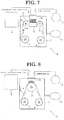
- a modification apparatus 16 of the resin film 6 according to the fourth embodiment of the present invention is explained in detail.
- the modification apparatus 16 according to the fourth embodiment is different from the modification apparatus 13 according to the third embodiment in that there is provided a partition plate 17 partitioning into a space where the shower head 15 is provided and a space where the supply roll 7 and the take-up roll 8 are provided. Therefore, structures similar to those of the modification apparatus 13 according to the third embodiment are designated by the same symbols, and different structures are explained in detail.
- the modification apparatus 16 has a chamber 2, an unsaturated hydrocarbon supply device 3, an ozone generating device 4, and a vacuum pump 5.
- the resin film 6 supplied from the supply roll 7 moves on the conveying roll 14 and is wound onto the take-up roll 8.
- the shower head 15 is provided to be opposed to this conveying roll 14.
- the partition plate 17 is provided in the chamber 2.
- the partition plate 17 is provided, for example, in the vicinity of the conveying roll 14 and partitions the chamber 2 into a modification treatment space 2a for conducting modification of the resin film 6 and a storing space 2b for storing the resin film 6 before the treatment (and after the treatment).
- the modification treatment space 2a is provided with the shower head 15, and the modification treatment space 2a is provided with the vacuum pump 5 through a pipe.
- the storing space 2b is provided with the supply roll 7 and the take-up roll 8.
- an inert gas for example, nitrogen gas, etc.
- the supply roll 7 onto which the resin film 6 has been wound is set in the chamber 2, and the chamber is evacuated, for example, to several pascals or less. While the resin film 6 supplied from the supply roll 7 is wound onto the take-up roll 8, the high-concentration ozone gas and the unsaturated hydrocarbon gas are supplied from the shower head 15 to the resin film 6, and the gas in the chamber 2 (modification treatment space 2a) is discharged to the outside by the vacuum pump 5 such that pressure in the chamber 2 becomes several thousand pascals or less (e.g., 3,000 pascals or less).
- modification apparatus 16 according to the fourth embodiment of the present invention similar to the modification apparatus 13 according to the third embodiment, it is possible to improve the surface of the resin film 6 in hydrophilicity and to conduct a modification treatment of the resin film 6 that is small in wettability effect disappearance after the modification treatment.
- the modification apparatus 16 it is possible by providing the partition plate 17 to decrease the reactive gas (high-concentration ozone gas, unsaturated hydrocarbon gas and the reaction products) flowing into the storing space 2b. Furthermore, it is possible to further reduce the reactive gas flowing into the storing space 2b by supplying an inert gas into the storing space 2b to decrease the pressure difference between the modification treatment space 2a and the storing space 2b.
- the reactive gas high-concentration ozone gas, unsaturated hydrocarbon gas and the reaction products
- the present invention's resin modification method and modification apparatus were explained in detail by showing specific embodiments, but the present invention's resin modification method and modification apparatus are not limited to the embodiments. Their designs can suitably be changed in an extent of not damaging characteristics of the invention, and the changed design modes are also included in the technical scope of the present invention.
- the discharge holes 10a, 10b of the shower head 10 are not limited to the modes of Figs. 2 , 3 .
Landscapes
- Chemical & Material Sciences (AREA)
- Organic Chemistry (AREA)
- General Chemical & Material Sciences (AREA)
- Health & Medical Sciences (AREA)
- Chemical Kinetics & Catalysis (AREA)
- Medicinal Chemistry (AREA)
- Polymers & Plastics (AREA)
- Inorganic Chemistry (AREA)
- Treatments Of Macromolecular Shaped Articles (AREA)
- Oxygen, Ozone, And Oxides In General (AREA)
Applications Claiming Priority (2)
| Application Number | Priority Date | Filing Date | Title |
|---|---|---|---|
| JP2015103305 | 2015-05-21 | ||
| PCT/JP2016/064555 WO2016186096A1 (ja) | 2015-05-21 | 2016-05-17 | 樹脂の改質方法及び改質装置 |
Publications (3)
| Publication Number | Publication Date |
|---|---|
| EP3299409A1 EP3299409A1 (en) | 2018-03-28 |
| EP3299409A4 EP3299409A4 (en) | 2019-02-13 |
| EP3299409B1 true EP3299409B1 (en) | 2020-06-24 |
Family
ID=57319944
Family Applications (1)
| Application Number | Title | Priority Date | Filing Date |
|---|---|---|---|
| EP16796489.9A Active EP3299409B1 (en) | 2015-05-21 | 2016-05-17 | Method and device for modifying resin |
Country Status (6)
| Country | Link |
|---|---|
| US (1) | US10053548B2 (zh) |
| EP (1) | EP3299409B1 (zh) |
| JP (1) | JP6057030B1 (zh) |
| KR (1) | KR101925501B1 (zh) |
| CN (1) | CN107614580B (zh) |
| WO (1) | WO2016186096A1 (zh) |
Families Citing this family (4)
| Publication number | Priority date | Publication date | Assignee | Title |
|---|---|---|---|---|
| CN111902564B (zh) * | 2018-03-28 | 2022-01-11 | 株式会社明电舍 | 氧化物膜形成方法 |
| JP6645562B1 (ja) * | 2018-11-30 | 2020-02-14 | 株式会社明電舎 | 分解性樹脂成形体および分解性樹脂成形体の製造方法 |
| JP6806205B1 (ja) | 2019-08-28 | 2021-01-06 | 株式会社明電舎 | 多孔質材料の改質方法 |
| JP6860048B2 (ja) * | 2019-08-30 | 2021-04-14 | 株式会社明電舎 | 原子層堆積方法 |
Family Cites Families (21)
| Publication number | Priority date | Publication date | Assignee | Title |
|---|---|---|---|---|
| US3928664A (en) * | 1973-01-17 | 1975-12-23 | Du Pont | Ozone treatment of elastomers |
| JPH03195745A (ja) * | 1989-12-25 | 1991-08-27 | Tosoh Corp | 高分子構造物表面の改質方法 |
| EP0424873A3 (en) | 1989-10-24 | 1992-05-27 | Tosoh Corporation | Method for modifying the surface of a polymer article |
| JPH04283912A (ja) | 1991-03-12 | 1992-10-08 | Fuji Photo Film Co Ltd | 磁気記録媒体の製造方法 |
| JP2963975B2 (ja) | 1995-06-06 | 1999-10-18 | 工業技術院長 | シリコン酸化膜の形成方法 |
| JP4286158B2 (ja) * | 2004-01-30 | 2009-06-24 | 株式会社明電舎 | オゾン処理装置 |
| TW200613762A (en) | 2004-10-27 | 2006-05-01 | Optimax Tech Corp | Method for decreasing contact angle of an optical thin film by utilizing ozone |
| JP4849863B2 (ja) * | 2005-10-14 | 2012-01-11 | 株式会社明電舎 | 酸化膜形成方法 |
| JP5072288B2 (ja) * | 2006-08-25 | 2012-11-14 | 株式会社明電舎 | ゲート絶縁膜の形成方法、半導体素子の製造装置 |
| JP4952375B2 (ja) | 2007-05-23 | 2012-06-13 | 株式会社明電舎 | レジスト除去方法及びその装置 |
| JP4905253B2 (ja) * | 2007-05-23 | 2012-03-28 | 株式会社明電舎 | レジスト除去方法及びその装置 |
| US7767767B2 (en) * | 2007-10-01 | 2010-08-03 | Equistar Chemicals, Lp | Modification of polyethylene with ozone |
| JP4968028B2 (ja) | 2007-12-04 | 2012-07-04 | 株式会社明電舎 | レジスト除去装置 |
| US8574369B2 (en) * | 2007-12-04 | 2013-11-05 | Meidensha Corporation | Method of removing resist and apparatus therefor |
| JP5287558B2 (ja) * | 2008-11-21 | 2013-09-11 | 株式会社明電舎 | 基板処理方法 |
| JP2012197477A (ja) | 2011-03-22 | 2012-10-18 | Panasonic Corp | 薄膜製造方法および装置 |
| JP5891609B2 (ja) | 2011-05-30 | 2016-03-23 | 株式会社明電舎 | 不動態化処理方法 |
| JP5962124B2 (ja) * | 2012-03-28 | 2016-08-03 | 株式会社明電舎 | 酸化膜の形成方法 |
| EP2865523B1 (en) | 2012-06-20 | 2018-06-06 | Toyobo Co., Ltd. | Process for producing layered product and layered product |
| JP5971718B2 (ja) * | 2012-10-29 | 2016-08-17 | 株式会社明電舎 | 半導体装置製造方法 |
| WO2014203892A1 (ja) | 2013-06-20 | 2014-12-24 | コニカミノルタ株式会社 | ガスバリア性フィルム、およびその製造方法 |
-
2016
- 2016-05-17 CN CN201680028950.2A patent/CN107614580B/zh active Active
- 2016-05-17 JP JP2016532640A patent/JP6057030B1/ja active Active
- 2016-05-17 US US15/575,225 patent/US10053548B2/en active Active
- 2016-05-17 KR KR1020177036503A patent/KR101925501B1/ko active IP Right Grant
- 2016-05-17 EP EP16796489.9A patent/EP3299409B1/en active Active
- 2016-05-17 WO PCT/JP2016/064555 patent/WO2016186096A1/ja active Application Filing
Non-Patent Citations (1)
| Title |
|---|
| None * |
Also Published As
| Publication number | Publication date |
|---|---|
| CN107614580A (zh) | 2018-01-19 |
| JPWO2016186096A1 (ja) | 2017-06-08 |
| EP3299409A1 (en) | 2018-03-28 |
| CN107614580B (zh) | 2018-11-20 |
| JP6057030B1 (ja) | 2017-01-11 |
| EP3299409A4 (en) | 2019-02-13 |
| US20180148558A1 (en) | 2018-05-31 |
| KR101925501B1 (ko) | 2018-12-05 |
| US10053548B2 (en) | 2018-08-21 |
| WO2016186096A1 (ja) | 2016-11-24 |
| KR20180006448A (ko) | 2018-01-17 |
Similar Documents
| Publication | Publication Date | Title |
|---|---|---|
| EP3299409B1 (en) | Method and device for modifying resin | |
| US20190112711A1 (en) | Roll-To-Roll Atomic Layer Deposition Apparatus and Method | |
| JP5081712B2 (ja) | 成膜装置 | |
| US10253148B2 (en) | Method and device for modifying resin | |
| US20130084409A1 (en) | Method and Device for Atmospheric Pressure Plasma Treatment | |
| EP2243859A1 (en) | Thin film forming method and thin film stack | |
| US8999062B2 (en) | Film depositing apparatus | |
| JP5562723B2 (ja) | 成膜方法、成膜装置、およびガスバリアフィルムの製造方法 | |
| US9243331B2 (en) | Apparatus for producing laminated body | |
| US20070272153A1 (en) | Apparatus for low-temperature plasma treatment | |
| WO2016132901A1 (ja) | ガスバリアーフィルム及びその製造方法 | |
| JP2011179084A (ja) | 大気圧プラズマ装置 | |
| JP5024925B2 (ja) | 大気圧プラズマ処理方法 | |
| JP2000204179A (ja) | シ―ト状物の連続プラズマ表面処理方法及び装置 | |
| US20200131627A1 (en) | Heat treatment apparatus for a vacuum chamber, deposition apparatus for depositing material on a flexible substrate, method of heat treatment of a flexible substrate in a vacuum chamber, and method for processing a flexible substrate | |
| JP6287537B2 (ja) | 脱ガス装置 | |
| JP2006351437A (ja) | 表面処理装置及び表面処理方法 |
Legal Events
| Date | Code | Title | Description |
|---|---|---|---|
| STAA | Information on the status of an ep patent application or granted ep patent |
Free format text: STATUS: THE INTERNATIONAL PUBLICATION HAS BEEN MADE |
|
| PUAI | Public reference made under article 153(3) epc to a published international application that has entered the european phase |
Free format text: ORIGINAL CODE: 0009012 |
|
| STAA | Information on the status of an ep patent application or granted ep patent |
Free format text: STATUS: REQUEST FOR EXAMINATION WAS MADE |
|
| 17P | Request for examination filed |
Effective date: 20171218 |
|
| AK | Designated contracting states |
Kind code of ref document: A1 Designated state(s): AL AT BE BG CH CY CZ DE DK EE ES FI FR GB GR HR HU IE IS IT LI LT LU LV MC MK MT NL NO PL PT RO RS SE SI SK SM TR |
|
| AX | Request for extension of the european patent |
Extension state: BA ME |
|
| DAV | Request for validation of the european patent (deleted) | ||
| DAX | Request for extension of the european patent (deleted) | ||
| A4 | Supplementary search report drawn up and despatched |
Effective date: 20190115 |
|
| RIC1 | Information provided on ipc code assigned before grant |
Ipc: C08J 7/12 20060101AFI20190110BHEP Ipc: C01B 13/10 20060101ALI20190110BHEP |
|
| GRAP | Despatch of communication of intention to grant a patent |
Free format text: ORIGINAL CODE: EPIDOSNIGR1 |
|
| STAA | Information on the status of an ep patent application or granted ep patent |
Free format text: STATUS: GRANT OF PATENT IS INTENDED |
|
| INTG | Intention to grant announced |
Effective date: 20200117 |
|
| GRAS | Grant fee paid |
Free format text: ORIGINAL CODE: EPIDOSNIGR3 |
|
| GRAA | (expected) grant |
Free format text: ORIGINAL CODE: 0009210 |
|
| STAA | Information on the status of an ep patent application or granted ep patent |
Free format text: STATUS: THE PATENT HAS BEEN GRANTED |
|
| AK | Designated contracting states |
Kind code of ref document: B1 Designated state(s): AL AT BE BG CH CY CZ DE DK EE ES FI FR GB GR HR HU IE IS IT LI LT LU LV MC MK MT NL NO PL PT RO RS SE SI SK SM TR |
|
| REG | Reference to a national code |
Ref country code: GB Ref legal event code: FG4D |
|
| REG | Reference to a national code |
Ref country code: CH Ref legal event code: EP |
|
| REG | Reference to a national code |
Ref country code: DE Ref legal event code: R096 Ref document number: 602016038811 Country of ref document: DE |
|
| REG | Reference to a national code |
Ref country code: AT Ref legal event code: REF Ref document number: 1283844 Country of ref document: AT Kind code of ref document: T Effective date: 20200715 |
|
| REG | Reference to a national code |
Ref country code: IE Ref legal event code: FG4D |
|
| PG25 | Lapsed in a contracting state [announced via postgrant information from national office to epo] |
Ref country code: NO Free format text: LAPSE BECAUSE OF FAILURE TO SUBMIT A TRANSLATION OF THE DESCRIPTION OR TO PAY THE FEE WITHIN THE PRESCRIBED TIME-LIMIT Effective date: 20200924 Ref country code: SE Free format text: LAPSE BECAUSE OF FAILURE TO SUBMIT A TRANSLATION OF THE DESCRIPTION OR TO PAY THE FEE WITHIN THE PRESCRIBED TIME-LIMIT Effective date: 20200624 Ref country code: GR Free format text: LAPSE BECAUSE OF FAILURE TO SUBMIT A TRANSLATION OF THE DESCRIPTION OR TO PAY THE FEE WITHIN THE PRESCRIBED TIME-LIMIT Effective date: 20200925 Ref country code: LT Free format text: LAPSE BECAUSE OF FAILURE TO SUBMIT A TRANSLATION OF THE DESCRIPTION OR TO PAY THE FEE WITHIN THE PRESCRIBED TIME-LIMIT Effective date: 20200624 Ref country code: FI Free format text: LAPSE BECAUSE OF FAILURE TO SUBMIT A TRANSLATION OF THE DESCRIPTION OR TO PAY THE FEE WITHIN THE PRESCRIBED TIME-LIMIT Effective date: 20200624 |
|
| REG | Reference to a national code |
Ref country code: LT Ref legal event code: MG4D |
|
| PG25 | Lapsed in a contracting state [announced via postgrant information from national office to epo] |
Ref country code: BG Free format text: LAPSE BECAUSE OF FAILURE TO SUBMIT A TRANSLATION OF THE DESCRIPTION OR TO PAY THE FEE WITHIN THE PRESCRIBED TIME-LIMIT Effective date: 20200924 Ref country code: HR Free format text: LAPSE BECAUSE OF FAILURE TO SUBMIT A TRANSLATION OF THE DESCRIPTION OR TO PAY THE FEE WITHIN THE PRESCRIBED TIME-LIMIT Effective date: 20200624 Ref country code: RS Free format text: LAPSE BECAUSE OF FAILURE TO SUBMIT A TRANSLATION OF THE DESCRIPTION OR TO PAY THE FEE WITHIN THE PRESCRIBED TIME-LIMIT Effective date: 20200624 Ref country code: LV Free format text: LAPSE BECAUSE OF FAILURE TO SUBMIT A TRANSLATION OF THE DESCRIPTION OR TO PAY THE FEE WITHIN THE PRESCRIBED TIME-LIMIT Effective date: 20200624 |
|
| REG | Reference to a national code |
Ref country code: NL Ref legal event code: MP Effective date: 20200624 |
|
| REG | Reference to a national code |
Ref country code: AT Ref legal event code: MK05 Ref document number: 1283844 Country of ref document: AT Kind code of ref document: T Effective date: 20200624 |
|
| PG25 | Lapsed in a contracting state [announced via postgrant information from national office to epo] |
Ref country code: AL Free format text: LAPSE BECAUSE OF FAILURE TO SUBMIT A TRANSLATION OF THE DESCRIPTION OR TO PAY THE FEE WITHIN THE PRESCRIBED TIME-LIMIT Effective date: 20200624 Ref country code: NL Free format text: LAPSE BECAUSE OF FAILURE TO SUBMIT A TRANSLATION OF THE DESCRIPTION OR TO PAY THE FEE WITHIN THE PRESCRIBED TIME-LIMIT Effective date: 20200624 |
|
| PG25 | Lapsed in a contracting state [announced via postgrant information from national office to epo] |
Ref country code: EE Free format text: LAPSE BECAUSE OF FAILURE TO SUBMIT A TRANSLATION OF THE DESCRIPTION OR TO PAY THE FEE WITHIN THE PRESCRIBED TIME-LIMIT Effective date: 20200624 Ref country code: SM Free format text: LAPSE BECAUSE OF FAILURE TO SUBMIT A TRANSLATION OF THE DESCRIPTION OR TO PAY THE FEE WITHIN THE PRESCRIBED TIME-LIMIT Effective date: 20200624 Ref country code: PT Free format text: LAPSE BECAUSE OF FAILURE TO SUBMIT A TRANSLATION OF THE DESCRIPTION OR TO PAY THE FEE WITHIN THE PRESCRIBED TIME-LIMIT Effective date: 20201026 Ref country code: CZ Free format text: LAPSE BECAUSE OF FAILURE TO SUBMIT A TRANSLATION OF THE DESCRIPTION OR TO PAY THE FEE WITHIN THE PRESCRIBED TIME-LIMIT Effective date: 20200624 Ref country code: ES Free format text: LAPSE BECAUSE OF FAILURE TO SUBMIT A TRANSLATION OF THE DESCRIPTION OR TO PAY THE FEE WITHIN THE PRESCRIBED TIME-LIMIT Effective date: 20200624 Ref country code: RO Free format text: LAPSE BECAUSE OF FAILURE TO SUBMIT A TRANSLATION OF THE DESCRIPTION OR TO PAY THE FEE WITHIN THE PRESCRIBED TIME-LIMIT Effective date: 20200624 Ref country code: IT Free format text: LAPSE BECAUSE OF FAILURE TO SUBMIT A TRANSLATION OF THE DESCRIPTION OR TO PAY THE FEE WITHIN THE PRESCRIBED TIME-LIMIT Effective date: 20200624 Ref country code: AT Free format text: LAPSE BECAUSE OF FAILURE TO SUBMIT A TRANSLATION OF THE DESCRIPTION OR TO PAY THE FEE WITHIN THE PRESCRIBED TIME-LIMIT Effective date: 20200624 |
|
| PG25 | Lapsed in a contracting state [announced via postgrant information from national office to epo] |
Ref country code: PL Free format text: LAPSE BECAUSE OF FAILURE TO SUBMIT A TRANSLATION OF THE DESCRIPTION OR TO PAY THE FEE WITHIN THE PRESCRIBED TIME-LIMIT Effective date: 20200624 Ref country code: SK Free format text: LAPSE BECAUSE OF FAILURE TO SUBMIT A TRANSLATION OF THE DESCRIPTION OR TO PAY THE FEE WITHIN THE PRESCRIBED TIME-LIMIT Effective date: 20200624 Ref country code: IS Free format text: LAPSE BECAUSE OF FAILURE TO SUBMIT A TRANSLATION OF THE DESCRIPTION OR TO PAY THE FEE WITHIN THE PRESCRIBED TIME-LIMIT Effective date: 20201024 |
|
| REG | Reference to a national code |
Ref country code: DE Ref legal event code: R097 Ref document number: 602016038811 Country of ref document: DE |
|
| PG25 | Lapsed in a contracting state [announced via postgrant information from national office to epo] |
Ref country code: DK Free format text: LAPSE BECAUSE OF FAILURE TO SUBMIT A TRANSLATION OF THE DESCRIPTION OR TO PAY THE FEE WITHIN THE PRESCRIBED TIME-LIMIT Effective date: 20200624 |
|
| PLBE | No opposition filed within time limit |
Free format text: ORIGINAL CODE: 0009261 |
|
| STAA | Information on the status of an ep patent application or granted ep patent |
Free format text: STATUS: NO OPPOSITION FILED WITHIN TIME LIMIT |
|
| 26N | No opposition filed |
Effective date: 20210325 |
|
| PG25 | Lapsed in a contracting state [announced via postgrant information from national office to epo] |
Ref country code: SI Free format text: LAPSE BECAUSE OF FAILURE TO SUBMIT A TRANSLATION OF THE DESCRIPTION OR TO PAY THE FEE WITHIN THE PRESCRIBED TIME-LIMIT Effective date: 20200624 |
|
| REG | Reference to a national code |
Ref country code: CH Ref legal event code: PL |
|
| GBPC | Gb: european patent ceased through non-payment of renewal fee |
Effective date: 20210517 |
|
| PG25 | Lapsed in a contracting state [announced via postgrant information from national office to epo] |
Ref country code: CH Free format text: LAPSE BECAUSE OF NON-PAYMENT OF DUE FEES Effective date: 20210531 Ref country code: LU Free format text: LAPSE BECAUSE OF NON-PAYMENT OF DUE FEES Effective date: 20210517 Ref country code: LI Free format text: LAPSE BECAUSE OF NON-PAYMENT OF DUE FEES Effective date: 20210531 Ref country code: MC Free format text: LAPSE BECAUSE OF FAILURE TO SUBMIT A TRANSLATION OF THE DESCRIPTION OR TO PAY THE FEE WITHIN THE PRESCRIBED TIME-LIMIT Effective date: 20200624 |
|
| REG | Reference to a national code |
Ref country code: BE Ref legal event code: MM Effective date: 20210531 |
|
| PG25 | Lapsed in a contracting state [announced via postgrant information from national office to epo] |
Ref country code: IE Free format text: LAPSE BECAUSE OF NON-PAYMENT OF DUE FEES Effective date: 20210517 Ref country code: GB Free format text: LAPSE BECAUSE OF NON-PAYMENT OF DUE FEES Effective date: 20210517 |
|
| PG25 | Lapsed in a contracting state [announced via postgrant information from national office to epo] |
Ref country code: FR Free format text: LAPSE BECAUSE OF NON-PAYMENT OF DUE FEES Effective date: 20210531 |
|
| PG25 | Lapsed in a contracting state [announced via postgrant information from national office to epo] |
Ref country code: BE Free format text: LAPSE BECAUSE OF NON-PAYMENT OF DUE FEES Effective date: 20210531 |
|
| PG25 | Lapsed in a contracting state [announced via postgrant information from national office to epo] |
Ref country code: HU Free format text: LAPSE BECAUSE OF FAILURE TO SUBMIT A TRANSLATION OF THE DESCRIPTION OR TO PAY THE FEE WITHIN THE PRESCRIBED TIME-LIMIT; INVALID AB INITIO Effective date: 20160517 |
|
| PG25 | Lapsed in a contracting state [announced via postgrant information from national office to epo] |
Ref country code: CY Free format text: LAPSE BECAUSE OF FAILURE TO SUBMIT A TRANSLATION OF THE DESCRIPTION OR TO PAY THE FEE WITHIN THE PRESCRIBED TIME-LIMIT Effective date: 20200624 |
|
| PGFP | Annual fee paid to national office [announced via postgrant information from national office to epo] |
Ref country code: DE Payment date: 20230519 Year of fee payment: 8 |
|
| PG25 | Lapsed in a contracting state [announced via postgrant information from national office to epo] |
Ref country code: MK Free format text: LAPSE BECAUSE OF FAILURE TO SUBMIT A TRANSLATION OF THE DESCRIPTION OR TO PAY THE FEE WITHIN THE PRESCRIBED TIME-LIMIT Effective date: 20200624 |
|
| PG25 | Lapsed in a contracting state [announced via postgrant information from national office to epo] |
Ref country code: TR Free format text: LAPSE BECAUSE OF FAILURE TO SUBMIT A TRANSLATION OF THE DESCRIPTION OR TO PAY THE FEE WITHIN THE PRESCRIBED TIME-LIMIT Effective date: 20200624 |