EP3299308B1 - Klappbarer ladungsträger und verfahren zur bereitstellung eines klappbaren ladungsträgers - Google Patents
Klappbarer ladungsträger und verfahren zur bereitstellung eines klappbaren ladungsträgers Download PDFInfo
- Publication number
- EP3299308B1 EP3299308B1 EP17191152.2A EP17191152A EP3299308B1 EP 3299308 B1 EP3299308 B1 EP 3299308B1 EP 17191152 A EP17191152 A EP 17191152A EP 3299308 B1 EP3299308 B1 EP 3299308B1
- Authority
- EP
- European Patent Office
- Prior art keywords
- group
- gas spring
- roof
- stand
- load carrier
- Prior art date
- Legal status (The legal status is an assumption and is not a legal conclusion. Google has not performed a legal analysis and makes no representation as to the accuracy of the status listed.)
- Active
Links
Images


Classifications
-
- B—PERFORMING OPERATIONS; TRANSPORTING
- B65—CONVEYING; PACKING; STORING; HANDLING THIN OR FILAMENTARY MATERIAL
- B65D—CONTAINERS FOR STORAGE OR TRANSPORT OF ARTICLES OR MATERIALS, e.g. BAGS, BARRELS, BOTTLES, BOXES, CANS, CARTONS, CRATES, DRUMS, JARS, TANKS, HOPPERS, FORWARDING CONTAINERS; ACCESSORIES, CLOSURES, OR FITTINGS THEREFOR; PACKAGING ELEMENTS; PACKAGES
- B65D19/00—Pallets or like platforms, with or without side walls, for supporting loads to be lifted or lowered
- B65D19/02—Rigid pallets with side walls, e.g. box pallets
- B65D19/06—Rigid pallets with side walls, e.g. box pallets with bodies formed by uniting or interconnecting two or more components
- B65D19/08—Rigid pallets with side walls, e.g. box pallets with bodies formed by uniting or interconnecting two or more components made wholly or mainly of metal
- B65D19/12—Collapsible pallets
-
- B—PERFORMING OPERATIONS; TRANSPORTING
- B65—CONVEYING; PACKING; STORING; HANDLING THIN OR FILAMENTARY MATERIAL
- B65D—CONTAINERS FOR STORAGE OR TRANSPORT OF ARTICLES OR MATERIALS, e.g. BAGS, BARRELS, BOTTLES, BOXES, CANS, CARTONS, CRATES, DRUMS, JARS, TANKS, HOPPERS, FORWARDING CONTAINERS; ACCESSORIES, CLOSURES, OR FITTINGS THEREFOR; PACKAGING ELEMENTS; PACKAGES
- B65D2519/00—Pallets or like platforms, with or without side walls, for supporting loads to be lifted or lowered
- B65D2519/00004—Details relating to pallets
- B65D2519/00258—Overall construction
- B65D2519/00263—Overall construction of the pallet
- B65D2519/00273—Overall construction of the pallet made of more than one piece
-
- B—PERFORMING OPERATIONS; TRANSPORTING
- B65—CONVEYING; PACKING; STORING; HANDLING THIN OR FILAMENTARY MATERIAL
- B65D—CONTAINERS FOR STORAGE OR TRANSPORT OF ARTICLES OR MATERIALS, e.g. BAGS, BARRELS, BOTTLES, BOXES, CANS, CARTONS, CRATES, DRUMS, JARS, TANKS, HOPPERS, FORWARDING CONTAINERS; ACCESSORIES, CLOSURES, OR FITTINGS THEREFOR; PACKAGING ELEMENTS; PACKAGES
- B65D2519/00—Pallets or like platforms, with or without side walls, for supporting loads to be lifted or lowered
- B65D2519/00004—Details relating to pallets
- B65D2519/00258—Overall construction
- B65D2519/00283—Overall construction of the load supporting surface
- B65D2519/00293—Overall construction of the load supporting surface made of more than one piece
-
- B—PERFORMING OPERATIONS; TRANSPORTING
- B65—CONVEYING; PACKING; STORING; HANDLING THIN OR FILAMENTARY MATERIAL
- B65D—CONTAINERS FOR STORAGE OR TRANSPORT OF ARTICLES OR MATERIALS, e.g. BAGS, BARRELS, BOTTLES, BOXES, CANS, CARTONS, CRATES, DRUMS, JARS, TANKS, HOPPERS, FORWARDING CONTAINERS; ACCESSORIES, CLOSURES, OR FITTINGS THEREFOR; PACKAGING ELEMENTS; PACKAGES
- B65D2519/00—Pallets or like platforms, with or without side walls, for supporting loads to be lifted or lowered
- B65D2519/00004—Details relating to pallets
- B65D2519/00258—Overall construction
- B65D2519/00313—Overall construction of the base surface
- B65D2519/00323—Overall construction of the base surface made of more than one piece
-
- B—PERFORMING OPERATIONS; TRANSPORTING
- B65—CONVEYING; PACKING; STORING; HANDLING THIN OR FILAMENTARY MATERIAL
- B65D—CONTAINERS FOR STORAGE OR TRANSPORT OF ARTICLES OR MATERIALS, e.g. BAGS, BARRELS, BOTTLES, BOXES, CANS, CARTONS, CRATES, DRUMS, JARS, TANKS, HOPPERS, FORWARDING CONTAINERS; ACCESSORIES, CLOSURES, OR FITTINGS THEREFOR; PACKAGING ELEMENTS; PACKAGES
- B65D2519/00—Pallets or like platforms, with or without side walls, for supporting loads to be lifted or lowered
- B65D2519/00004—Details relating to pallets
- B65D2519/00258—Overall construction
- B65D2519/00313—Overall construction of the base surface
- B65D2519/00328—Overall construction of the base surface shape of the contact surface of the base
- B65D2519/00338—Overall construction of the base surface shape of the contact surface of the base contact surface having a discrete foot-like shape
-
- B—PERFORMING OPERATIONS; TRANSPORTING
- B65—CONVEYING; PACKING; STORING; HANDLING THIN OR FILAMENTARY MATERIAL
- B65D—CONTAINERS FOR STORAGE OR TRANSPORT OF ARTICLES OR MATERIALS, e.g. BAGS, BARRELS, BOTTLES, BOXES, CANS, CARTONS, CRATES, DRUMS, JARS, TANKS, HOPPERS, FORWARDING CONTAINERS; ACCESSORIES, CLOSURES, OR FITTINGS THEREFOR; PACKAGING ELEMENTS; PACKAGES
- B65D2519/00—Pallets or like platforms, with or without side walls, for supporting loads to be lifted or lowered
- B65D2519/00004—Details relating to pallets
- B65D2519/00258—Overall construction
- B65D2519/00492—Overall construction of the side walls
- B65D2519/00532—Frame structures
-
- B—PERFORMING OPERATIONS; TRANSPORTING
- B65—CONVEYING; PACKING; STORING; HANDLING THIN OR FILAMENTARY MATERIAL
- B65D—CONTAINERS FOR STORAGE OR TRANSPORT OF ARTICLES OR MATERIALS, e.g. BAGS, BARRELS, BOTTLES, BOXES, CANS, CARTONS, CRATES, DRUMS, JARS, TANKS, HOPPERS, FORWARDING CONTAINERS; ACCESSORIES, CLOSURES, OR FITTINGS THEREFOR; PACKAGING ELEMENTS; PACKAGES
- B65D2519/00—Pallets or like platforms, with or without side walls, for supporting loads to be lifted or lowered
- B65D2519/00004—Details relating to pallets
- B65D2519/00547—Connections
- B65D2519/00671—Connections structures connecting corner posts to the pallet
- B65D2519/00676—Structures intended to be disassembled
- B65D2519/00681—Hinges
-
- B—PERFORMING OPERATIONS; TRANSPORTING
- B65—CONVEYING; PACKING; STORING; HANDLING THIN OR FILAMENTARY MATERIAL
- B65D—CONTAINERS FOR STORAGE OR TRANSPORT OF ARTICLES OR MATERIALS, e.g. BAGS, BARRELS, BOTTLES, BOXES, CANS, CARTONS, CRATES, DRUMS, JARS, TANKS, HOPPERS, FORWARDING CONTAINERS; ACCESSORIES, CLOSURES, OR FITTINGS THEREFOR; PACKAGING ELEMENTS; PACKAGES
- B65D2519/00—Pallets or like platforms, with or without side walls, for supporting loads to be lifted or lowered
- B65D2519/00004—Details relating to pallets
- B65D2519/00547—Connections
- B65D2519/00706—Connections structures connecting the lid or cover to the side walls or corner posts
- B65D2519/00716—Connections structures connecting the lid or cover to the side walls or corner posts non-removable lid or covers
- B65D2519/00721—Connections structures connecting the lid or cover to the side walls or corner posts non-removable lid or covers hinged lids
-
- B—PERFORMING OPERATIONS; TRANSPORTING
- B65—CONVEYING; PACKING; STORING; HANDLING THIN OR FILAMENTARY MATERIAL
- B65D—CONTAINERS FOR STORAGE OR TRANSPORT OF ARTICLES OR MATERIALS, e.g. BAGS, BARRELS, BOTTLES, BOXES, CANS, CARTONS, CRATES, DRUMS, JARS, TANKS, HOPPERS, FORWARDING CONTAINERS; ACCESSORIES, CLOSURES, OR FITTINGS THEREFOR; PACKAGING ELEMENTS; PACKAGES
- B65D2519/00—Pallets or like platforms, with or without side walls, for supporting loads to be lifted or lowered
- B65D2519/00004—Details relating to pallets
- B65D2519/00736—Details
- B65D2519/0081—Elements or devices for locating articles
Definitions
- the present invention relates to a hinged load carrier having a bottom group, at least one first pillar group and a second pillar group, which are each connected by means of a rotation axis movable with the bottom group, and with a roof group, which is connected by means of a Rotationsache with at least one of the two pillar groups ,
- the invention relates to a method for providing a folding load carrier with a bottom group, a first post group, a second post group and a roof group in which the two post groups are each moved about an axis of rotation in a vertical position or a first holding position and the roof group about an axis of rotation is moved relative to the rooftop group connected to the first or second post group in a horizontal position or a second holding position.
- charge carriers are well known from the prior art.
- charge carriers are used to transport components, with the empty load carrier having to be brought to its new location after unloading the components.
- the carrier is unfolded to be refilled. Due to the necessary stability of such carriers, they usually have a relatively high weight, so that the unfolding process for the contracting staff is feasible only under difficult conditions.
- the DE 195 01 111 A1 discloses a hinged load carrier with a bottom element, a first and a second side element, which are each connected by means of a rotation axis movable with the bottom element.
- a roof element is movably connected to one of the two side elements by means of a rotation axis, wherein the charge carrier comprises a first gas spring for supporting a first folding movement of the side elements about the respective associated axis of rotation and a second gas spring for supporting a second folding movement of the roof element about its axis of rotation.
- a cargo container which consists of a floor construction, a ceiling construction with interposed two side walls and two end walls.
- the side walls have a longitudinal pitch and three rows of hinges for folding.
- a drive device allows unfolding of the cargo container.
- the drive device comprises a pull cylinder / pressure cylinder per frontal wall and / or each side wall, which is arranged between the foldable walls and / or the floor construction and / or the ceiling construction.
- the US 2004/0232146 A1 discloses a collapsible delivery container with hinged legs that fold inwardly to allow the top of the container to collapse toward the bottom of the container.
- the container is configured so that one side after the other can be folded.
- the container includes a lifting assist mechanism which carries a portion of the weight of the container when collapsed and raised.
- the mentioned charge carriers have the disadvantage that they can all be at least partially built or folded only under difficult conditions.
- Object of the present invention is therefore to provide a carrier with improved ergonomics.
- the object is achieved by a hinged charge carrier and a method for providing a hinged charge carrier according to the independent patent claims.
- a folding load carrier with a bottom group, at least a first pillar group and a second pillar group.
- the two stayer groups are each connected by means of a rotation axis movable with the bottom group.
- the charge carrier furthermore comprises a roof group.
- the roof group is connected by means of a rotation axis movable with one of the two stayer groups.
- To support a first folding movement of the first and / or second pillar group about the respective associated axis of rotation of the charge carrier comprises a first gas spring.
- the charge carrier comprises a second gas spring.
- At least two different states are preferably provided for the charge carrier.
- the charge carrier is in an unfolded state for the transport of components to their destination.
- the load carrier is in a folded state for its own transport to its place of use.
- the charge carrier preferably has a smaller volume in the folded state than in the unfolded state.
- the bottom group is preferably arranged in the vertical direction at the lowest point.
- the two pillar groups are rotated about the respective axis of rotation, so that they are arranged one above the other in the vertical direction, in particular folded.
- One of the two stayer groups is connected to the roof group via the rotation axis.
- the roof group is preferably arranged in the folded state between the affiliated group of stayer and the floor assembly.
- the first gas spring is preferably designed to at least partially neutralize the weight of the stayer group connected to the roof group, so that the first folding movement can be carried out with significantly reduced expenditure of force.
- the first or second upright group which is not connected to the roof group, can be manually raised to build up the load carrier.
- the charge carrier has an additional gas spring for lifting the first or second upright group not connected to the roof group.
- the roof group After lifting the two stayer groups, the roof group is initially preferably still arranged almost parallel or slightly oblique to the associated Steherou, in particular folded on this. So that the charge carrier is provided fully unfolded, the roof group must be raised by the rotation thing, so that it is arranged substantially horizontally.
- This second folding movement is now supported by the second gas spring, so that the high weight of the roof group, to which preferably means for receiving components are provided, is at least partially neutralized.
- the entire folding process can thus be carried out very ergonomically, since the force required for this purpose is significantly reduced by the two gas springs.
- the folding of the charge carrier by the first and second gas spring can be supported.
- the first gas spring is at least in operative connection with the first upright group. Due to the operative connection, the first folding movement of the first upright group, which is preferably connected to the roof group, relative to the floor group can be carried out.
- the first gas spring preferably has at least one cylinder with a piston.
- the cylinder is preferably with the connected to the roof group Steher michle and the piston connected to the bottom group. To push the piston out of the cylinder and thus trigger the first folding movement, the piston is released in the cylinder, whereby the piston is pushed out by the prevailing in the cylinder pressure from this. By pushing out the cylinder at the same time the stayer group is pushed upwards.
- the piston is pushed back into the cylinder, so that the associated group of stanchions is lowered by executing the first folding movement.
- the upright groups and the bottom group can be in operative connection with several gas springs.
- it can be individually determined how much the first folding movement should be supported by the first gas spring.
- the first gas spring the weight completely or only partially compensate.
- both stayer groups are each in operative connection with a gas spring.
- the second gas spring is at least in operative connection with the roof group and the first pillar group or the second pillar group.
- the second gas spring preferably has at least one cylinder with a piston.
- the cylinder is preferably connected to the roof group and the piston to the upright group.
- the piston is pushed out of the cylinder, whereby the roof group is raised to perform the second folding movement.
- several gas springs can be in operative connection with the roof group and the respective upright group.
- the strength of the weight balance can be set individually to achieve optimal ergonomic success.
- the first folding movement of the first and / or second pillar group preferably extends from a substantially horizontal position of the respective pillar group into a substantially vertical position of the pillar group.
- a first holding position is preferably achieved in the horizontal position.
- both stayer groups can have such a gas spring.
- the piston is blocked in the cylinder of the first gas spring, so that the pillar group connected to the piston is held in the desired position, in particular the first holding position.
- the roof group is moved from a substantially vertical position, which runs parallel or slightly oblique to the post group connected to the roof group, in a substantially horizontal position, in particular parallel to the floor group, or vice versa.
- This movement defines the second folding movement about the axis of rotation.
- the roof group by means of the second gas spring in a second holding position of the second folding movement is durable.
- the roof group is durable by means of a holding mechanism in the second holding position of the second folding movement.
- the second holding position can be positioned in the region of the entire second folding movement.
- the roof group does not fall back into its vertical position, but remains in the current position, in particular in the second holding position, due to the corresponding design of the second gas spring. Damage to the load carrier is thereby prevented.
- the roof group can preferably be fixed folded on the upright group, so that the roof group when folding of the carrier can not move unintentionally. In this case, the second stop position is already reached in the starting point of the second folding movement. As a result, the transport of the charge carrier itself is facilitated.
- the first gas spring is designed as a blocking gas spring.
- the standing with the roof group in operative connection second gas spring is designed as a blocking gas spring.
- Blocking gas springs preferably allow the associated components, in particular the two post groups and / or the roof group, to be blocked in any desired holding position. The blocking can be arbitrarily solved and operated. As a result, a controlled and, in particular, power-saving construction of the charge carrier is made possible.
- the roof group can be folded around the axis of rotation to the stayer group and held there, even without the use of an additional holding mechanism.
- the two stayer groups, the roof group and the floor group are preferably arranged horizontally and folded over each other.
- the first gas spring is a self-locking gas spring.
- Diarretierende gas springs are preferably characterized by the fact that the piston can be detected mechanically in its retracted position. By applying pressure to the self-locking gas spring associated Sther michell the lock is released, so that the gas spring extends automatically. As a result, the stayer group is almost automatically offset in the first folding movement and thus raised.
- the person who is to provide the carrier can thus preferably only with his foot on with the self-locking Tilt the gas spring into an engaged group of posts so that it is pressed down slightly to trigger the first folding movement. It is therefore no longer necessary that the operator must stoop down to raise the stayer group under great effort.
- the second gas spring may be formed as a self-locking gas spring to simply raise the roof group. The ergonomics of the load carrier is positively influenced by the corresponding design of the first and / or second gas spring.
- the roof group can be fixed by means of the holding mechanism in the folded state on the upright group.
- the holding mechanism is advantageously a belt, Velcro or hooks.
- the holding mechanism is preferably formed on the connected to the roof group Steher michell and on the roof group itself.
- the release mechanism is preferably a Bowden cable.
- the Bowden cable can be designed as a direct or indirect release mechanism.
- the direct Bowden cable is preferably formed by a release button with lever, by means of which the respective gas spring is triggered.
- the indirect Bowden cable comprises an actuating unit, which is arranged at a distance from the gas springs, and the Bowden cable itself. Via the Bowden cable, a trigger head is activated as a result of actuation of the actuating unit, so that the respective gas spring is triggered.
- the folding and positioning of the charge carrier can be done by the release mechanism very simple and ergonomic.
- the bottom group in the region of the axes of rotation of the two pillar groups each have a releasable axle connection.
- the two uprights are raised to perform the first folding movement and rotated substantially 90 degrees about the axis of rotation until they have reached a vertical position of the first folding movement.
- the detachable axle connection is designed in such a way that the respectively assigned upright group engages in the axle connection and is held in the vertical position.
- the charge carrier comprises a third gas spring.
- the folding movement of the first stayer group is divided into two force ranges.
- the first force range in particular at the beginning of the first folding movement, an increased effort is required to raise the first group of stakes.
- the third gas spring is connected to the first post group and the bottom group.
- the range of action of the third gas spring is limited to this first force range in which the highest load occurs.
- the second force range which occurs towards the end of the first folding movement, a lesser amount of force is required to fully move the first group of stanchions into their first holding position.
- the first gas spring acts with a lower force than the third gas spring, since the force in the second force range is to be set lower than in the first force range.
- the third gas spring is effective in the second force range, in particular by the limited effective range.
- the first force range is preferably described by the first two thirds of the first folding movement, whereas the second force range is described by the last third of the folding movement.
- the third gas spring is connected via a boundary, advantageously with a rail or a slot, with the bottom group. This makes it possible, for example, that the effect of the third gas spring or its attacks can be changed depending on the position of attachment of the third gas spring in the limit.
- the limitation allows a shift of the attachment point of the third gas spring in the floor assembly and causes, for example, that when fully off or retracted gas spring Steher caravan can be moved further by the attachment point is moved within the limit.
- the roof group and the stayer group which is not connected via the axis of rotation with the roof group, are connected by a releasable attachment mechanism.
- the roof group is thereby held in a horizontal position of the second folding movement.
- the horizontal position of the roof group is preferably achieved after the first or second post group connected to the roof group has been raised, preferably engaged in the detachable axle connection of the underbody and the roof group has been raised upwards along the second folding movement until it is aligned substantially parallel to the floor group , In this horizontal position of the roof group, the axis of rotation opposite side of the roof group is connected to the other Steher mich.
- the roof group is connected via the axis of rotation with the first Steher michell and by means of the releasable attachment mechanism with the second Steherou.
- the roof group and the second post group comprise a part of the attachment mechanism.
- the attachment mechanism is preferably a spring latch. The charge carrier thus has a high stability.
- the support of the first gas spring in the first folding movement is regulated by a controller.
- the support of the second gas spring is adjustable with the controller.
- the controller preferably comprises at least one actuating element, by means of which the input and / or Ausschub ausschub ausschub ausschub ausschub ausschub ausschub ausschub ausschub ausschub ausschub ausschub ausschub ausschub ausschub ausschub ausschub ausschub ausschub ausschub ausschub ausschub ausschub ausschub ausschub ausschub ausschub ausschub ausschub ausschub ausschub ausschub ausschub ausschub ausschub ausschub ausschub ausschub ausschub ausschub ausschub ausschub ausschub ausschub ausschub ausschub ausschub ausschub auss
- the carrier has a flexible réellegefache for receiving components.
- the réellegefache is preferably removed from the charge carrier.
- the two post groups are each moved about an axis of rotation in a vertical position or a first stop position.
- the roof group is moved about an axis of rotation relative to the first or second post group connected to the roof group in a horizontal position or a second holding position.
- the movement of at least the first of the two pillar groups is supported by means of a first gas spring and the movement of the roof group is supported by means of a second gas spring.
- the charge carrier is designed according to the preceding description.
- the bottom group, the two upright groups and the roof group are preferably arranged one above the other in the vertical direction.
- the first pillar group is preferably connected to the roof group via the axis of rotation.
- the roof group is folded to the first Steher michlex, the first Steherrien and the roof group are folded together on the axis of rotation of the first Steher micha on the floor group.
- the second upright group is pivoted about its axis of rotation, so that it is substantially vertical in relation to the above the roof group connected second Steheruci is arranged. It is also conceivable that the second post group is placed directly above the floor group and above it the first post group connected to the roof group. The order of arrangement of the two pillar groups in the vertical direction is irrelevant to the mode of operation of the charge carrier.
- the overhead second upright group is first manually pivoted upwards, wherein it preferably engages in an axle connection of the underbody.
- the second upright group is thus moved from a horizontal position to the vertical position, whereby preferably the first folding movement is defined.
- the second pillar group is preferably fixed, so that it can not accidentally fold down.
- first Steherou is folded around its axis of rotation upwards.
- the first pillar group is preferably moved from the substantially horizontal position in the folded state of the charge carrier in its vertical position.
- this preferably also engages in an axle connection of the floor pan.
- This first folding movement of the first Steherou is supported by the first and third gas spring according to the invention.
- the first and third gas spring the common weight of the first pillar group and the associated roof group is preferably neutralized.
- the roof group is now in the vertical position together with the first post group, the roof group preferably being folded onto the first post group.
- the roof group is raised along its axis of rotation until it is in its horizontal position.
- the rotation of the roof group from the vertical position to the horizontal position preferably defines the second folding movement.
- the lifting of the roof group is supported according to the invention by the second gas spring.
- the weight of the roof group will be At least partially balanced by the second gas spring, so that this step with little effort is feasible.
- the placement of the charge carrier can be done by the gas springs almost automatically, so that the risks of overloading the staff are significantly reduced.
- first gas spring is advantageously releasably locked.
- the first gas spring is configured such that its piston locks in the cylinder when the piston is pressed into the cylinder.
- first gas spring may be designed to block, in order to keep the respective post group in the intended holding position. This avoids that the stayer groups can unintentionally release from their holding position.
- the FIG. 1 shows a schematic view of a folded charge carrier 1.
- the charge carrier 1 comprises a bottom group 2, a first pillar group 3, a second pillar group 4 and a roof group 5.
- the first pillar group 3 is rotatably connected via a first axis of rotation 6 with the bottom group 2.
- the second pillar group 4 is connected via a second axis of rotation 7 rotatably connected to the bottom group 2.
- the bottom group 2 In the region of the two axes of rotation 6, 7, the bottom group 2 each have a first axle connection 8 and a second axle connection 9.
- the two axle 8, 9 are each formed by two U-profiles 34, which are arranged one behind the other in the sheet direction.
- the two pillars 3, 4 each have a frame 35 (see. Fig. 5 ) arranged round or square profiles 36.
- the frame 35 is rotatable about the respectively associated first or second rotation axis 6, 7 relative to the bottom group 2.
- the axle 8, 9 not shown in detail latching means which respectively with the two pillar groups 3, 4, in particular the adjacent thereto frame part, so that the respective pillar group 3, 4, as in the FIG. 4 represented, can be held by the locking means in the two axle 8, 9.
- the two pillars 3, 4 are in a horizontal position 10 and are arranged substantially one above the other.
- none of the components protrudes beyond the height of the axle connections 8, 9, as a result of which the charge carrier 1 has a very compact design.
- the charge carrier 1 also has at least one first gas spring 11 and a second gas spring 22.
- the first gas spring 11 is connected to the first post group 3 and the bottom group 2, so that the first post group 3 can be raised and lowered about its axis of rotation 6.
- the first gas spring 11 is designed to neutralize the weight of the indirectly and / or directly connected components, in particular the first post group 3 and the roof group 5.
- the second gas spring 22 is connected to the first post group 3 and the roof group 5.
- the roof group 5 is rotatably connected to the first pillar group 3 about a rotation axis 18. The lifting and / or lowering of the roof group 5 is supported by the second gas spring 22.
- the second pillar group 4 is arranged above the first pillar group 3.
- the first pillar group 3 could be arranged above the second pillar group 4.
- the second posture group 4 is raised and moved from the horizontal position 10 to a vertical position 12. For fixing the second pillar group 4, this preferably engages in the second axle joint 9 of the floor assembly 2.
- the movement of the second posture group 4 from the horizontal position 10 into the vertical position 12 describes a first folding movement 13, which is indicated by an arrow.
- the first folding movement 13 is carried out in the opposite direction, so that the second stake group 4 is lowered from the vertical position 12 into the horizontal position 10.
- the second axle connection 9 between the floor assembly 2 and the second support group 4 is previously released.
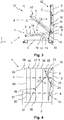
- the FIG. 3 shows a third step of the construction of the charge carrier 1.
- the second pillar group 4 is held in the vertical position 12.
- the first upright group 3 and roof group 5 are initially arranged in the horizontal position 10.
- the first pillar 3 is operatively connected to the first gas spring 11, so that its weight is substantially neutralized during lifting.
- the first gas spring 11 is designed as a self-locking gas spring 14. In order to actuate the self-locking gas spring 14 and thus trigger the first folding movement 13 of the first pillar group 3, the first pillar group 3 must be pressed down along a z-axis.
- a detent, not shown, of the self-locking gas spring 14 so that a first piston 15 is pushed out of a first cylinder 16 of the self-locking gas spring 14 is released.
- the first piston 15 is connected to the bottom group 2 and the first cylinder 16 to the first pillar group 3.
- the first piston 15 extends out of the first cylinder 16, at the same time the first pillar group 3 is pushed upwards.
- the first pillar group 3 is raised from its horizontal position 10 into the vertical position 12.
- the first pillar group 3 can, if necessary, in a first holding position 17, which in the FIG. 3 is shown dashed, held.
- the first holding position 17 preferably occupies the first post group 3 in the horizontal position 10.
- any further holding position 17 would be conceivable for the convenient construction and dismantling of the load carrier 1.
- the charge carrier for example, according to the FIG. 4 a réellegefache 29, which warp when folding up the first Steher mich 3 and thereby block the structure of the charge carrier 1.
- the first upright group 3 can be positioned in the first holding position 17.
- the first piston 15 is locked in the first cylinder 16, so that the first posture group 3 can no longer be raised.
- the locking of the first piston 15, in particular by briefly pressing the first piston 15 of the first gas spring 11, are released, so that the first folding movement 13 is carried out further.
- the self-locking gas spring 14 is shown only in the horizontal position 10 and the vertical position 12.
- the upright group 3 also in the first holding position 17, the first gas spring 11, in particular the self-locking gas spring 14, on.
- the first holding position 17 can be taken along the entire folding movement 13, as well in the vertical position 12 and in the horizontal position 10.
- the first group of stanchions 3 engage in the detachable first axle connection 8 of the underbody.
- the roof group 5 is in FIG. 3 Folded to the first Steherelle 3 and is with her in each occupied horizontal position 10, vertical position 12 or first stop position 17.
- the roof group 5 is held by a holding mechanism 19 to the first posture group 3, so that the roof group 5 can not move unintentionally.
- the holding mechanism 19 is a belt 20. After the first upright group 3 in the vertical position 12, in particular in the first axle 8 of the floor assembly 2, is locked, the roof group 5 itself is to perform a second folding movement 21. The belt 20 is released for this purpose.
- the first axle connection 8 between the bottom group 3 and the first pillar group 3 is released.
- the first upright group 3 is folded down on the bottom group 2 along the first folding movement 13 until it is arranged essentially in the horizontal position 10.
- the first folding movement 13 is supported by the first gas spring 11 when lowering the first pillar 3 as well as in the lifting.
- the first gas spring 11 is provided only for equalizing the force during installation of the charge carrier.
- the self-locking gas spring 14 is locked again.
- the first pillar 3 can also be done by any other suitable means.
- the FIG. 4 shows the third step of setting up the charge carrier 1.
- the first upright group 3 is connected via the rotation axis 18 with the roof group 5.
- the roof group 5 is from its vertical position 12 (see. Fig. 3 ), in which it is folded onto the first upright group 3, raised to the horizontal position 10. This lifting of the roof group 5 about the axis of rotation 18 describes the second folding movement 21.
- the roof group 5 is in operative connection with the second gas spring 22.
- the second gas spring 22 is a blocking gas spring 23 with a second piston 24 and a second cylinder 25.
- the piston 24 is connected to the first pillar group 3 and the second cylinder 25 to the roof group 5.
- the charge carrier 1 comprises in particular a controller 27 for controlling the intensity of the support of the first and / or second gas spring 11, 22.
- the controller 27 is preferably connected to at least one of the two gas springs 11, 12, so that for example by actuation of the control of Overpressure in the cylinder 25, 16 can be additionally increased, so that the pistons 15, 24 with increased force from the respectively associated cylinder 25, 16 pushed out.
- the controller 27 can only be used to trigger the gas spring 11, 12.
- the attachment mechanism 28 may be formed as a bar, strap or hook.
- the roof group 5 is indirectly connected to the second pillar group 4.
- the blocking gas spring 23 is preferably in the vertical position 12 (see. Fig. 3 ), so that the roof group 5 can not move unintentionally about the axis of rotation 18.
- the roof group 5 no additional holding mechanism 19 according to the FIG. 3 on, since the blocking gas spring 23 fulfills the function of holding the roof group 5 in a predetermined position.
- the roof group 5 can be held by means of the blocking gas spring 23 a second holding position 26. So it would be possible, for example, the roof group 5 according to the dashed version of FIG. 4 to position in order to perform possibly necessary intermediate steps.
- the charge carrier 1 on a réellegefache 29 for receiving components not shown.
- the réellegefache 29 is preferably flexible. For this purpose, for example, textile and / or pliable materials are suitable.
- the inner compartment 29 has a plurality of juxtaposed and each other arranged compartments 37, which are separated by side walls 38 from each other.
- the réellegefache 29 is preferably connected by not shown loops or rings with the roof group 5.
- the roof group 5 is formed, for example, from one or more in the sheet direction one behind the other arranged round profiles 39, so that the Certainlygefache 29 can be moved by means of loops or rings along the roof group 5.
- the attachment mechanism 28 is released.
- the charge carrier has a release mechanism 30.
- the release mechanism 30 may be, for example, a Bowden cable, which is not shown in detail.
- the second gas spring 23 can be actuated manually or by means of a release mechanism 30.
- the roof group 5 by means of holding mechanism 19 (see. Fig. 3 ) held in their position.
- the FIG. 5 shows the established carrier 1 in a perspective view.
- the charge carrier 1 is set up according to the preceding description.
- the roof group 5 is connected to the second pillar 4 by means of the fastening mechanism 28.
- the fixing mechanism 28 is a spring latch 31.
- the spring latch 31 is released, for example, by the release mechanism 30, so that the roof group 5 can be lowered along its axis of rotation 18.
- the FIG. 6 shows the charge carrier 1 according to another embodiment.
- the focus is placed on different embodiments of the solution mechanism 30a, 30b.
- a release mechanism 30a is arranged in the region of the first or second axle connection 8, 9 of the floor assembly 2 in order to release this axle connection 8, 9, so that the first folding movement (cf. Fig. 2 and Fig. 3 ) of the first or second pillar group 3, 4 is triggered.
- the FIG. 6 shows the second pillar group 4, wherein the first pillar group 3 may be formed analogously.
- the release mechanism 30a comprises transverse struts 32 which have to be compressed, whereby the operative connection between the axle connections 8, 9 and the respectively assigned first or second upright group 3, 4 is interrupted.
- the pillar groups 3, 4 can then be moved along their axes of rotation 6, 7 (cf. Fig. 2 and Fig. 3 ).
- the release mechanism 30b is arranged in the region of the roof group 5.
- the release mechanism 30b is designed to hold the attachment mechanism 28, in particular the spring latch 31, according to FIG FIG. 5 to solve.
- the release mechanism 30b comprises a latch 33 operatively connected to the attachment mechanism 28. When this latch 33 is released, the roof assembly 5 can be folded to fold the charge carrier 1 along its axis of rotation (see FIG. Fig. 4 ) to be turned around.
- the charge carrier 1 in addition to the first gas spring 11 for supporting the first folding movement 10 of the first pillar group 3 according to the invention additionally comprises a third gas spring 40.
- the first gas spring 11 is arranged substantially parallel to the first pillar group 3.
- the third gas spring 40 is arranged obliquely to the first pillar group 3.
- the third gas spring 40 is connected via a boundary 41, in particular a rail or a slot, with the bottom group 2. By means of the boundary 41, an area of action of the third gas spring 40 is defined.
- the first folding movement 13 can essentially be classified into a first load region 42 with a high load and a second force region 43 with a load that is lower in comparison to the first force region 42.
- the first force region 42 is described when the first pillar group 3 from its horizontal position 10 in accordance with FIG. 3 is raised.
- the end of the first force range 42 is approximately reached when the first post group 60 to 80 percent of the first folding movement 13 has executed.
- the boundary 41 of the third gas spring 40 is designed such that the third gas spring 40 supports the lifting of the first pillar group 3 in this first force region 42.
- the further the first pillar group 3 is moved in the direction of the vertical position 12, the lower the load to be supported.
- the region of the lower load is described by the second force region 43.
- the lifting of the first pillar 3 is supported by the first gas spring 11.
- the third gas spring 40 is preferably, in particular by the boundary 41, without effect.
- the present invention is not limited to the illustrated and described embodiments. Variations within the scope of the claims are also possible as a combination of features, even if they are shown and described in different embodiments.
Landscapes
- Engineering & Computer Science (AREA)
- Mechanical Engineering (AREA)
- Tents Or Canopies (AREA)
- Fittings On The Vehicle Exterior For Carrying Loads, And Devices For Holding Or Mounting Articles (AREA)
- Handcart (AREA)
Priority Applications (1)
| Application Number | Priority Date | Filing Date | Title |
|---|---|---|---|
| PL17191152T PL3299308T3 (pl) | 2016-09-23 | 2017-09-14 | Składany pojemnik ładunkowy i sposób przygotowania składanego pojemnika ładunkowego |
Applications Claiming Priority (2)
| Application Number | Priority Date | Filing Date | Title |
|---|---|---|---|
| DE102016118021.1A DE102016118021A1 (de) | 2016-09-23 | 2016-09-23 | Klappbarer Ladungsträger und Verfahren zur Bereitstellung eines klappbaren Ladungsträgers |
| DE102016123341 | 2016-12-02 |
Publications (2)
| Publication Number | Publication Date |
|---|---|
| EP3299308A1 EP3299308A1 (de) | 2018-03-28 |
| EP3299308B1 true EP3299308B1 (de) | 2019-07-24 |
Family
ID=59895144
Family Applications (1)
| Application Number | Title | Priority Date | Filing Date |
|---|---|---|---|
| EP17191152.2A Active EP3299308B1 (de) | 2016-09-23 | 2017-09-14 | Klappbarer ladungsträger und verfahren zur bereitstellung eines klappbaren ladungsträgers |
Country Status (5)
| Country | Link |
|---|---|
| EP (1) | EP3299308B1 (pl) |
| ES (1) | ES2752209T3 (pl) |
| HU (1) | HUE046785T2 (pl) |
| PL (1) | PL3299308T3 (pl) |
| PT (1) | PT3299308T (pl) |
Families Citing this family (2)
| Publication number | Priority date | Publication date | Assignee | Title |
|---|---|---|---|---|
| DK180580B1 (en) * | 2020-01-06 | 2021-09-06 | Maersk As | A collapsible rack for supporting carcasses inside refrigerated inter- modal containers and a method for collapsing such rack |
| DE102020120353B4 (de) * | 2020-07-31 | 2023-07-27 | Willibald Hergeth | Palette mit beweglichem Ladeboden |
Family Cites Families (4)
| Publication number | Priority date | Publication date | Assignee | Title |
|---|---|---|---|---|
| DE19501111C2 (de) * | 1995-01-16 | 1999-03-18 | Rockwool Mineralwolle | Transportvorrichtung für großvolumiges Stückgut |
| US6468015B1 (en) * | 2001-04-25 | 2002-10-22 | Konstant Products, Inc. | Container pick and return system |
| DE10219709A1 (de) * | 2001-05-03 | 2002-11-07 | Werner Mueller | Frachtbehälter |
| US20040232146A1 (en) * | 2003-05-20 | 2004-11-25 | Kessler John E. | Collapsible shipping container |
-
2017
- 2017-09-14 EP EP17191152.2A patent/EP3299308B1/de active Active
- 2017-09-14 PL PL17191152T patent/PL3299308T3/pl unknown
- 2017-09-14 HU HUE17191152A patent/HUE046785T2/hu unknown
- 2017-09-14 PT PT171911522T patent/PT3299308T/pt unknown
- 2017-09-14 ES ES17191152T patent/ES2752209T3/es active Active
Non-Patent Citations (1)
| Title |
|---|
| None * |
Also Published As
| Publication number | Publication date |
|---|---|
| HUE046785T2 (hu) | 2020-03-30 |
| EP3299308A1 (de) | 2018-03-28 |
| PL3299308T3 (pl) | 2020-01-31 |
| ES2752209T3 (es) | 2020-04-03 |
| PT3299308T (pt) | 2019-10-31 |
Similar Documents
| Publication | Publication Date | Title |
|---|---|---|
| DD295974A5 (de) | Verbesserter klapptisch | |
| EP1538271A2 (de) | Erweiterbarer Container | |
| EP3369348B1 (de) | Verkaufs- und transportbehälter zur warenpräsentation | |
| EP3299308B1 (de) | Klappbarer ladungsträger und verfahren zur bereitstellung eines klappbaren ladungsträgers | |
| DE202007006234U1 (de) | Tisch mit vergrößerbarer Tischplatte | |
| EP3265624B1 (de) | Fächerartiger sonnen- oder wetterschutz | |
| DE102019125729B3 (de) | Faltbarer Strukturrahmen für einen Wagen | |
| DE3600245A1 (de) | Geruest | |
| EP2910511B1 (de) | Fahrkorb mit verstellbarem Schutzdach | |
| AT501357B1 (de) | Behälter | |
| DE3614877A1 (de) | Transportwagen zur aufnahme verschiedener gueter, insbesondere waesche | |
| EP2149490B1 (de) | Fahrzeugaufbau für Nutzfahrzeuge mit höhenverstellbaren Eckrungen | |
| DE102011016701B4 (de) | Kuppelzelt | |
| DE102016118021A1 (de) | Klappbarer Ladungsträger und Verfahren zur Bereitstellung eines klappbaren Ladungsträgers | |
| DE60301149T2 (de) | Faltbarer Tischtennistisch | |
| DE2948453C2 (de) | Zusammenklappbarer Konsolenträger | |
| WO2012022387A2 (de) | Mastsystem | |
| EP2151372B1 (de) | Fahrzeugaufbau für Nutzfahrzeuge mit schwenkbarem heckseitigen Portal Balken von hinteren Türflügel | |
| DE102005001062B4 (de) | Anordnung zur Verriegelung eines Tischtennistisches | |
| DE102008035769C5 (de) | Fahrzeugaufbau für Nutzfahrzeuge | |
| DE202005018342U1 (de) | Runge für einen Planenaufbau | |
| DE202006010778U1 (de) | Transportierbarer Lift | |
| DE102009020665B4 (de) | Mobile Anlage zur Herstellung oder Bearbeitung industrieller Produkte | |
| DE102004007297B4 (de) | Erweiterbarer Container | |
| DE202007013212U1 (de) | Klapprunge |
Legal Events
| Date | Code | Title | Description |
|---|---|---|---|
| PUAI | Public reference made under article 153(3) epc to a published international application that has entered the european phase |
Free format text: ORIGINAL CODE: 0009012 |
|
| STAA | Information on the status of an ep patent application or granted ep patent |
Free format text: STATUS: THE APPLICATION HAS BEEN PUBLISHED |
|
| AK | Designated contracting states |
Kind code of ref document: A1 Designated state(s): AL AT BE BG CH CY CZ DE DK EE ES FI FR GB GR HR HU IE IS IT LI LT LU LV MC MK MT NL NO PL PT RO RS SE SI SK SM TR |
|
| AX | Request for extension of the european patent |
Extension state: BA ME |
|
| STAA | Information on the status of an ep patent application or granted ep patent |
Free format text: STATUS: REQUEST FOR EXAMINATION WAS MADE |
|
| 17P | Request for examination filed |
Effective date: 20180919 |
|
| RBV | Designated contracting states (corrected) |
Designated state(s): AL AT BE BG CH CY CZ DE DK EE ES FI FR GB GR HR HU IE IS IT LI LT LU LV MC MK MT NL NO PL PT RO RS SE SI SK SM TR |
|
| GRAP | Despatch of communication of intention to grant a patent |
Free format text: ORIGINAL CODE: EPIDOSNIGR1 |
|
| STAA | Information on the status of an ep patent application or granted ep patent |
Free format text: STATUS: GRANT OF PATENT IS INTENDED |
|
| INTG | Intention to grant announced |
Effective date: 20190212 |
|
| GRAS | Grant fee paid |
Free format text: ORIGINAL CODE: EPIDOSNIGR3 |
|
| GRAA | (expected) grant |
Free format text: ORIGINAL CODE: 0009210 |
|
| STAA | Information on the status of an ep patent application or granted ep patent |
Free format text: STATUS: THE PATENT HAS BEEN GRANTED |
|
| AK | Designated contracting states |
Kind code of ref document: B1 Designated state(s): AL AT BE BG CH CY CZ DE DK EE ES FI FR GB GR HR HU IE IS IT LI LT LU LV MC MK MT NL NO PL PT RO RS SE SI SK SM TR |
|
| REG | Reference to a national code |
Ref country code: GB Ref legal event code: FG4D Free format text: NOT ENGLISH |
|
| REG | Reference to a national code |
Ref country code: CH Ref legal event code: EP |
|
| REG | Reference to a national code |
Ref country code: DE Ref legal event code: R096 Ref document number: 502017001835 Country of ref document: DE |
|
| REG | Reference to a national code |
Ref country code: AT Ref legal event code: REF Ref document number: 1157895 Country of ref document: AT Kind code of ref document: T Effective date: 20190815 |
|
| REG | Reference to a national code |
Ref country code: IE Ref legal event code: FG4D Free format text: LANGUAGE OF EP DOCUMENT: GERMAN |
|
| REG | Reference to a national code |
Ref country code: RO Ref legal event code: EPE |
|
| REG | Reference to a national code |
Ref country code: PT Ref legal event code: SC4A Ref document number: 3299308 Country of ref document: PT Date of ref document: 20191031 Kind code of ref document: T Free format text: AVAILABILITY OF NATIONAL TRANSLATION Effective date: 20191022 |
|
| REG | Reference to a national code |
Ref country code: NL Ref legal event code: MP Effective date: 20190724 |
|
| REG | Reference to a national code |
Ref country code: LT Ref legal event code: MG4D |
|
| REG | Reference to a national code |
Ref country code: SK Ref legal event code: T3 Ref document number: E 32554 Country of ref document: SK |
|
| PG25 | Lapsed in a contracting state [announced via postgrant information from national office to epo] |
Ref country code: NL Free format text: LAPSE BECAUSE OF FAILURE TO SUBMIT A TRANSLATION OF THE DESCRIPTION OR TO PAY THE FEE WITHIN THE PRESCRIBED TIME-LIMIT Effective date: 20190724 Ref country code: HR Free format text: LAPSE BECAUSE OF FAILURE TO SUBMIT A TRANSLATION OF THE DESCRIPTION OR TO PAY THE FEE WITHIN THE PRESCRIBED TIME-LIMIT Effective date: 20190724 Ref country code: SE Free format text: LAPSE BECAUSE OF FAILURE TO SUBMIT A TRANSLATION OF THE DESCRIPTION OR TO PAY THE FEE WITHIN THE PRESCRIBED TIME-LIMIT Effective date: 20190724 Ref country code: NO Free format text: LAPSE BECAUSE OF FAILURE TO SUBMIT A TRANSLATION OF THE DESCRIPTION OR TO PAY THE FEE WITHIN THE PRESCRIBED TIME-LIMIT Effective date: 20191024 Ref country code: LT Free format text: LAPSE BECAUSE OF FAILURE TO SUBMIT A TRANSLATION OF THE DESCRIPTION OR TO PAY THE FEE WITHIN THE PRESCRIBED TIME-LIMIT Effective date: 20190724 |
|
| PG25 | Lapsed in a contracting state [announced via postgrant information from national office to epo] |
Ref country code: LV Free format text: LAPSE BECAUSE OF FAILURE TO SUBMIT A TRANSLATION OF THE DESCRIPTION OR TO PAY THE FEE WITHIN THE PRESCRIBED TIME-LIMIT Effective date: 20190724 Ref country code: RS Free format text: LAPSE BECAUSE OF FAILURE TO SUBMIT A TRANSLATION OF THE DESCRIPTION OR TO PAY THE FEE WITHIN THE PRESCRIBED TIME-LIMIT Effective date: 20190724 Ref country code: GR Free format text: LAPSE BECAUSE OF FAILURE TO SUBMIT A TRANSLATION OF THE DESCRIPTION OR TO PAY THE FEE WITHIN THE PRESCRIBED TIME-LIMIT Effective date: 20191025 Ref country code: IS Free format text: LAPSE BECAUSE OF FAILURE TO SUBMIT A TRANSLATION OF THE DESCRIPTION OR TO PAY THE FEE WITHIN THE PRESCRIBED TIME-LIMIT Effective date: 20191124 Ref country code: AL Free format text: LAPSE BECAUSE OF FAILURE TO SUBMIT A TRANSLATION OF THE DESCRIPTION OR TO PAY THE FEE WITHIN THE PRESCRIBED TIME-LIMIT Effective date: 20190724 |
|
| REG | Reference to a national code |
Ref country code: HU Ref legal event code: AG4A Ref document number: E046785 Country of ref document: HU |
|
| PG25 | Lapsed in a contracting state [announced via postgrant information from national office to epo] |
Ref country code: TR Free format text: LAPSE BECAUSE OF FAILURE TO SUBMIT A TRANSLATION OF THE DESCRIPTION OR TO PAY THE FEE WITHIN THE PRESCRIBED TIME-LIMIT Effective date: 20190724 |
|
| PG25 | Lapsed in a contracting state [announced via postgrant information from national office to epo] |
Ref country code: DK Free format text: LAPSE BECAUSE OF FAILURE TO SUBMIT A TRANSLATION OF THE DESCRIPTION OR TO PAY THE FEE WITHIN THE PRESCRIBED TIME-LIMIT Effective date: 20190724 Ref country code: EE Free format text: LAPSE BECAUSE OF FAILURE TO SUBMIT A TRANSLATION OF THE DESCRIPTION OR TO PAY THE FEE WITHIN THE PRESCRIBED TIME-LIMIT Effective date: 20190724 |
|
| PG25 | Lapsed in a contracting state [announced via postgrant information from national office to epo] |
Ref country code: IS Free format text: LAPSE BECAUSE OF FAILURE TO SUBMIT A TRANSLATION OF THE DESCRIPTION OR TO PAY THE FEE WITHIN THE PRESCRIBED TIME-LIMIT Effective date: 20200224 Ref country code: SM Free format text: LAPSE BECAUSE OF FAILURE TO SUBMIT A TRANSLATION OF THE DESCRIPTION OR TO PAY THE FEE WITHIN THE PRESCRIBED TIME-LIMIT Effective date: 20190724 Ref country code: MC Free format text: LAPSE BECAUSE OF FAILURE TO SUBMIT A TRANSLATION OF THE DESCRIPTION OR TO PAY THE FEE WITHIN THE PRESCRIBED TIME-LIMIT Effective date: 20190724 |
|
| REG | Reference to a national code |
Ref country code: DE Ref legal event code: R097 Ref document number: 502017001835 Country of ref document: DE |
|
| PLBE | No opposition filed within time limit |
Free format text: ORIGINAL CODE: 0009261 |
|
| STAA | Information on the status of an ep patent application or granted ep patent |
Free format text: STATUS: NO OPPOSITION FILED WITHIN TIME LIMIT |
|
| PG2D | Information on lapse in contracting state deleted |
Ref country code: IS |
|
| PG25 | Lapsed in a contracting state [announced via postgrant information from national office to epo] |
Ref country code: LU Free format text: LAPSE BECAUSE OF NON-PAYMENT OF DUE FEES Effective date: 20190914 Ref country code: IE Free format text: LAPSE BECAUSE OF NON-PAYMENT OF DUE FEES Effective date: 20190914 |
|
| 26N | No opposition filed |
Effective date: 20200603 |
|
| PG25 | Lapsed in a contracting state [announced via postgrant information from national office to epo] |
Ref country code: SI Free format text: LAPSE BECAUSE OF FAILURE TO SUBMIT A TRANSLATION OF THE DESCRIPTION OR TO PAY THE FEE WITHIN THE PRESCRIBED TIME-LIMIT Effective date: 20190724 |
|
| REG | Reference to a national code |
Ref country code: CH Ref legal event code: PL |
|
| PG25 | Lapsed in a contracting state [announced via postgrant information from national office to epo] |
Ref country code: CY Free format text: LAPSE BECAUSE OF FAILURE TO SUBMIT A TRANSLATION OF THE DESCRIPTION OR TO PAY THE FEE WITHIN THE PRESCRIBED TIME-LIMIT Effective date: 20190724 |
|
| PG25 | Lapsed in a contracting state [announced via postgrant information from national office to epo] |
Ref country code: MT Free format text: LAPSE BECAUSE OF FAILURE TO SUBMIT A TRANSLATION OF THE DESCRIPTION OR TO PAY THE FEE WITHIN THE PRESCRIBED TIME-LIMIT Effective date: 20190724 |
|
| PG25 | Lapsed in a contracting state [announced via postgrant information from national office to epo] |
Ref country code: LI Free format text: LAPSE BECAUSE OF NON-PAYMENT OF DUE FEES Effective date: 20200930 Ref country code: CH Free format text: LAPSE BECAUSE OF NON-PAYMENT OF DUE FEES Effective date: 20200930 |
|
| GBPC | Gb: european patent ceased through non-payment of renewal fee |
Effective date: 20210914 |
|
| PG25 | Lapsed in a contracting state [announced via postgrant information from national office to epo] |
Ref country code: MK Free format text: LAPSE BECAUSE OF FAILURE TO SUBMIT A TRANSLATION OF THE DESCRIPTION OR TO PAY THE FEE WITHIN THE PRESCRIBED TIME-LIMIT Effective date: 20190724 |
|
| PG25 | Lapsed in a contracting state [announced via postgrant information from national office to epo] |
Ref country code: GB Free format text: LAPSE BECAUSE OF NON-PAYMENT OF DUE FEES Effective date: 20210914 |
|
| REG | Reference to a national code |
Ref country code: DE Ref legal event code: R082 Ref document number: 502017001835 Country of ref document: DE Representative=s name: PATENTANWAELTE CANZLER & BERGMEIER PARTNERSCHA, DE Ref country code: DE Ref legal event code: R082 Ref document number: 502017001835 Country of ref document: DE Representative=s name: GULDE & PARTNER PATENT- UND RECHTSANWALTSKANZL, DE Ref country code: DE Ref legal event code: R082 Ref document number: 502017001835 Country of ref document: DE Representative=s name: CANZLER & BERGMEIER PATENTANWAELTE PARTNERSCHA, DE |
|
| REG | Reference to a national code |
Ref country code: DE Ref legal event code: R082 Ref document number: 502017001835 Country of ref document: DE Representative=s name: PATENTANWAELTE CANZLER & BERGMEIER PARTNERSCHA, DE Ref country code: DE Ref legal event code: R082 Ref document number: 502017001835 Country of ref document: DE Representative=s name: CANZLER & BERGMEIER PATENTANWAELTE PARTNERSCHA, DE Ref country code: DE Ref legal event code: R082 Ref document number: 502017001835 Country of ref document: DE Representative=s name: GULDE & PARTNER PATENT- UND RECHTSANWALTSKANZL, DE |
|
| REG | Reference to a national code |
Ref country code: AT Ref legal event code: MM01 Ref document number: 1157895 Country of ref document: AT Kind code of ref document: T Effective date: 20220914 |
|
| PG25 | Lapsed in a contracting state [announced via postgrant information from national office to epo] |
Ref country code: AT Free format text: LAPSE BECAUSE OF NON-PAYMENT OF DUE FEES Effective date: 20220914 |
|
| PGFP | Annual fee paid to national office [announced via postgrant information from national office to epo] |
Ref country code: BG Payment date: 20240917 Year of fee payment: 8 |
|
| PGFP | Annual fee paid to national office [announced via postgrant information from national office to epo] |
Ref country code: DE Payment date: 20240923 Year of fee payment: 8 Ref country code: FI Payment date: 20240919 Year of fee payment: 8 |
|
| PGFP | Annual fee paid to national office [announced via postgrant information from national office to epo] |
Ref country code: PT Payment date: 20240905 Year of fee payment: 8 |
|
| PGFP | Annual fee paid to national office [announced via postgrant information from national office to epo] |
Ref country code: BE Payment date: 20240920 Year of fee payment: 8 |
|
| PGFP | Annual fee paid to national office [announced via postgrant information from national office to epo] |
Ref country code: FR Payment date: 20240924 Year of fee payment: 8 |
|
| PGFP | Annual fee paid to national office [announced via postgrant information from national office to epo] |
Ref country code: CZ Payment date: 20240830 Year of fee payment: 8 |
|
| PGFP | Annual fee paid to national office [announced via postgrant information from national office to epo] |
Ref country code: PL Payment date: 20240722 Year of fee payment: 8 |
|
| PGFP | Annual fee paid to national office [announced via postgrant information from national office to epo] |
Ref country code: HU Payment date: 20240905 Year of fee payment: 8 Ref country code: SK Payment date: 20240902 Year of fee payment: 8 |
|
| PGFP | Annual fee paid to national office [announced via postgrant information from national office to epo] |
Ref country code: RO Payment date: 20240905 Year of fee payment: 8 |
|
| PGFP | Annual fee paid to national office [announced via postgrant information from national office to epo] |
Ref country code: IT Payment date: 20240930 Year of fee payment: 8 Ref country code: ES Payment date: 20241018 Year of fee payment: 8 |
|
| REG | Reference to a national code |
Ref country code: DE Ref legal event code: R082 Ref document number: 502017001835 Country of ref document: DE Representative=s name: GULDE & PARTNER PATENT- UND RECHTSANWALTSKANZL, DE |