EP3297798B1 - Küchenhobel und applikator - Google Patents
Küchenhobel und applikator Download PDFInfo
- Publication number
- EP3297798B1 EP3297798B1 EP17715893.8A EP17715893A EP3297798B1 EP 3297798 B1 EP3297798 B1 EP 3297798B1 EP 17715893 A EP17715893 A EP 17715893A EP 3297798 B1 EP3297798 B1 EP 3297798B1
- Authority
- EP
- European Patent Office
- Prior art keywords
- applicator
- mandoline slicer
- guide surface
- insert
- blade
- Prior art date
- Legal status (The legal status is an assumption and is not a legal conclusion. Google has not performed a legal analysis and makes no representation as to the accuracy of the status listed.)
- Active
Links
Images
Classifications
-
- B—PERFORMING OPERATIONS; TRANSPORTING
- B26—HAND CUTTING TOOLS; CUTTING; SEVERING
- B26D—CUTTING; DETAILS COMMON TO MACHINES FOR PERFORATING, PUNCHING, CUTTING-OUT, STAMPING-OUT OR SEVERING
- B26D7/00—Details of apparatus for cutting, cutting-out, stamping-out, punching, perforating, or severing by means other than cutting
- B26D7/08—Means for treating work or cutting member to facilitate cutting
- B26D7/088—Means for treating work or cutting member to facilitate cutting by cleaning or lubricating
-
- B—PERFORMING OPERATIONS; TRANSPORTING
- B26—HAND CUTTING TOOLS; CUTTING; SEVERING
- B26D—CUTTING; DETAILS COMMON TO MACHINES FOR PERFORATING, PUNCHING, CUTTING-OUT, STAMPING-OUT OR SEVERING
- B26D3/00—Cutting work characterised by the nature of the cut made; Apparatus therefor
- B26D3/28—Splitting layers from work; Mutually separating layers by cutting
- B26D3/283—Household devices therefor
- B26D2003/285—Household devices therefor cutting one single slice at each stroke
-
- B—PERFORMING OPERATIONS; TRANSPORTING
- B26—HAND CUTTING TOOLS; CUTTING; SEVERING
- B26D—CUTTING; DETAILS COMMON TO MACHINES FOR PERFORATING, PUNCHING, CUTTING-OUT, STAMPING-OUT OR SEVERING
- B26D2210/00—Machines or methods used for cutting special materials
- B26D2210/02—Machines or methods used for cutting special materials for cutting food products, e.g. food slicers
Definitions
- the invention relates to a kitchen slicer with an applicator, as known for example from DE, according to the preamble of claim 1.
- kitchen slicers are used to cut foodstuffs. These slicers have at least one blade which is held in a base body along which the foodstuff is guided. By running the foodstuff over the blade, the foodstuff is cut into strips and/or slices. The cut strips or slices are guided downwards through the frame and separated from the foodstuff.
- Such devices usually have a guide surface on which the foodstuff is guided to the blade and over it while being subjected to a pressure force.
- a kitchen slicer is suitable for cutting items to be cut, such as fruit, vegetables or the like, into strips or slices, for example. It has a base body and at least one blade held in the base body for cutting pieces off the item to be cut.
- a guide surface is arranged on a feed side of the at least one blade, preferably an insert having at least part of the guide surface, for example inserted into the base body in a height-adjustable manner.
- the item to be cut can be guided along the guide surface towards the at least one blade.
- An applicator is intended to supply a fluid to the blade directly or indirectly. According to the invention, the applicator acts through the guide surface or is accommodated in the kitchen slicer in addition to the guide surface.
- a "blade” in the sense of the invention can generally be understood as a flat, band-shaped body which has a ground cutting edge arranged on a side edge in a longitudinal direction.
- the blade can preferably be made of metal, ceramic or other material with a high Rockwell hardness.
- the cutting edge of the blade is the pointed edge of the ground cutting edge, which can have various shapes.
- the cutting edge can, for example, be a straight, curved and/or have a wavy shape in order to be adapted to a particular cutting material for individual purposes, for example. For example, it may be intended that a desired cutting pattern is produced on the cutting surface of the cutting material by means of a serrated or wavy blade.
- acting through the guide surface in the sense of the invention is generally understood to mean that somewhere in the area of the guide surface, namely somewhere where the material to be cut is guided past, is the place where the applicator acts, either in which the guide surface is designed to be fluid-permeable in some areas and a movable element acting underneath as an applicator at least contributes to the fluid supply or the applicator partially replaces the guide surface in its function at least to a large extent.
- An applicator acting through the guide surface therefore does this in the sense of the invention even if, for example, it is incorporated in the kitchen slicer as a supplement to the guide surface and becomes a quasi-movable part of the guide surface.
- the teaching according to the invention has the advantage that the material being cut helps to transport the fluid to the blade. This prevents incorrect flow of fluid.
- the kitchen slicer 1 is suitable for cutting items to be cut, such as fruit, vegetables or the like. It has a base body 2 with at least one blade 4 held in the base body 2. It also has a guide surface 7 on which the item to be cut can be guided towards the blade 4.
- the guide surface 7 is designed on an insert 6, which can be inserted into the vegetable slicer 1 in a height-adjustable manner.
- the insert is shown in the Figures 1 and 4 to 6 shown separately.
- the invention also includes a vegetable slicer (not shown) with a guide surface firmly integrated into the base body and other components essential to the invention that are also integrated into the base body, such as the applicator described below.
- an applicator 8 is shown, which is intended to bring a fluid (not shown) into contact with the material to be cut (also not shown). It is therefore intended to indirectly supply a fluid to the blade 4.
- the applicator 8 is accommodated in the kitchen slicer 1, in the present case in the insert 6, so as to act through the guide surface 7.
- the applicator 8 is movably mounted in the insert, namely rotatably.
- the applicator 8 shown is a non-driven hollow shaft with a radial outer contour and is therefore a passive applicator.
- the applicator is rotatably mounted here because engagement can occur from both axial sides, around which engagement the applicator can rotate. The tighter the fit of the applicator in the engagement is designed, the more reliable friction is required from the material to be cut to cause rotation.
- the applicator rotates, which runs in a fluid, it conveys fluid carried along on its radial outer surface to the material to be cut and with it to the blade 4.
- the guide surface 7, and in this case also the insert 6, is inserted at a distance from the blade 4 into an opening 10 which interrupts the guide surface 7 in the guide direction of the material to be cut, namely in an opening 10 designed to match the shape of the applicator 8, in this case rectangular.
- the opening 10 is therefore located centrally in the guide surface 7 of the kitchen slicer 1, namely on the longitudinal axis of the kitchen slicer 1 aligned in the grating or guide direction.
- the distance of the opening 10 to the V-shaped blade 4 in this case is approximately 1 to 5 cm.
- the applicator 8 is accommodated in the insert 6 below the opening 10 and partially penetrates the opening 10 so that it can be removed without causing any damage.
- the applicator thus has an exit end facing away from the guide surface 7 below the insert and can also be removed without causing any damage.
- fastening container 20 In the illustrated embodiment, the container 20 forms a kind of scooping tub for the rotatable applicator 8.
- the applicator itself (in an embodiment not shown) or a receptacle 14, 14' formed in the opening 10 for supporting the applicator 8 has holding means 12, 12', in the present case holding means 12 formed positively in the receptacle, cf. Fig. 4 .
- Bevelled shaft stumps or pins are suitable, which holding means 12, 12' take on a function for the applicator 8 with regard to the mobility of the applicator 8 and with regard to holding the applicator 8 in relation to the guide surface 7.
- the presently bevelled shaft stumps function together as an axis for the rotatable and hollow applicator 8. Due to the bevels, the applicator can be pressed between the shaft stumps until they spring into the radial interior.
- locations of advantageous embodiments for a fluid reservoir 9, 9 ' , 9 " have been found in the base body 2 and/or in the insert 6 and/or attached to the insert in a non-destructively detachable manner and/or in the applicator 8. They could, for example, be designed to be closed by means of a valve (embodiment not shown).
- the applicator 8 has a surface contour 16 which comes into contact with the material to be cut and which influences the amount of fluid released. According to the invention, different contours may be used for different fluids.
- the fluid can be conveyed by means of the applicator without any supply line, namely directly from a reservoir 9 to the blade 4.
Landscapes
- Life Sciences & Earth Sciences (AREA)
- Forests & Forestry (AREA)
- Engineering & Computer Science (AREA)
- Mechanical Engineering (AREA)
- Food-Manufacturing Devices (AREA)
- Knives (AREA)
Description
- Die Erfindung betrifft einen Küchenhobel mit einem Applikator, wie beispielsweise aus DE bekannt, gemäß dem Oberbegriff des Anspruchs 1.
- Zum Schneiden von Nahrungsmitteln werden bekanntermaßen Küchenhobel verwendet, die zumindest eine Klinge aufweisen, welche in einem Grundkörper festgehalten ist, auf welchem das Nahrungsmittel entlanggeführt wird. Durch das Oberfahren der Klinge mit dem Nahrungsmittel, wird dieses in Streifen und/oder Scheiben geschnitten. Die abgeschnittenen Streifen oder Scheiben werden durch den Rahmen hindurch nach unten geleitet und von dem Nahrungsmittel separiert. Üblicherweise weisen derartige Vorrichtungen eine Führungsfläche auf, auf der das Nahrungsmittel bis zur Klinge hin und über dieses hinweg unter Beaufschlagung mit einer Andruckkraft geführt wird.
- Es sind Schneidmesser bekannt, die aus ernährungstechnischen Gründen sinnvoller Weise ein Fluid direkt oder indirekt auf die Klinge applizieren, sodass beim Schnitt das Gemüse möglichst unmittelbar vom Fluid an der Schnittfläche überzogen werden kann, wie es beispielsweise aus dem Dokument
DE 20 2014 000 963 U1 bekannt geworden ist. - Es besteht der Wunsch nach einer verbesserten Lösung zum Schneiden von Nahrungsmitteln mit gleichzeitiger Fluidapplikation.
- Die Aufgabe wird erfindungsgemäß gelöst, mittels eines Gemüsehobels mit den Merkmalen des Anspruchs 1.
- Vorteilhafte Ausgestaltungen, weitere Merkmale und Details der vorliegenden Erfindung ergeben sich aus den abhängigen Ansprüchen, der Beschreibung und der Zeichnung.
- Ein erfindungsgemäßer Küchenhobel ist zum Schneiden von Schneidgut, wie Obst, Gemüse oder dergleichen in beispielsweise Streifen oder Scheiben geeignet. Er hat einen Grundkörper und zumindest eine in dem Grundkörper gefasste Klinge, um Stücke von dem Schneidgut abzuschneiden. Auf einer Zuführseite der zumindest einen Klinge ist eine Führungsfläche angeordnet, bevorzugt ein Einsatz aufweisend zumindest einen Teil der Führungsfläche beispielsweise höhenverstellbar in den Grundkörper eingesetzt. Auf der Führungsfläche ist das Schneidgut zu der zumindest einen Klinge hin führbar. Ein Applikator ist dazu bestimmt, der Klinge direkt oder indirekt ein Fluid zuzuführen. Gemäß der Erfindung ist der Applikator durch die Führungsflache hindurch wirkend oder die Führungsfläche ergänzend in dem Küchenhobel aufgenommen.
- Unter einer "Klinge" im Sinne der Erfindung kann allgemein ein ebener bandförmiger Körper verstanden werden, welcher in einer Längsausrichtung eine an einer Seitenkante angeordnete geschliffene Schneide aufweist. Die Klinge kann hierbei bevorzugt aus Metall, Keramik oder anderem Material mit einer hohen Rockwellhärte gefertigt sein. Die Schnittkante der Klinge ist jene spitze Kante der geschliffenen Schneide, wobei diese verschiedene Formen aufweisen kann. Hierbei kann die Schneidkante beispielsweise eine gerade, gekrümmte und/oder gewellte Form aufweisen, um beispielsweise für individuell Zwecke an ein jeweiliges Schneidgut angepasst zu werden. So kann es beispielsweise beabsichtigt sein, dass mittels einer gezackten oder gewellten Klinge ein gewünschtes Schnittmuster auf der Schnittfläche des Schnittguts hervorgerufen wird.
- Unter "durch die Führungsfläche hindurch wirkend" im Sinne der Erfindung wird allgemein verstanden, dass irgendwo im Bereich der Führungsfläche, nämlich irgendwo dort, wo das Schneidgut vorbeigeführt wird, der Ort sein soll, wo der Applikator wirkt, entweder in dem die Führungsfläche bereichsweise Fluiddurchlässig ausgeführt ist und ein darunter wirkendes bewegbares Element als Applikator die Fluidzufuhr zumindest mitverursacht oder der Applikator die Führungsfläche bereichsweise in ihrer Funktion zumindest weitestgehend ersetzt. Ein durch die Führungsfläche hindurch wirkender Applikator tut dies demnach im Sinne der Erfindung auch dann, wenn er beispielsweise die Führungsfläche ergänzend in dem Küchenhobel aufgenommen ist und quasi bewegbarer Teil der Führungsfläche wird.
- Durch die erfindungsgemäße Lehre wird der Vorteil erreicht, dass das Schneidgut das Fluid mit zur Klinge transportieren hilft. Mithin werden Fehlflüsse des Fluid vermieden.
- Nachfolgend wird die Erfindung anhand eines in Figuren dargestellten Ausführungsbeispiels näher erläutert, in dem allerdings mit apostrophierten Bezugsziffern alternative und ebenfalls erfindungsgemäße Ausgestaltungsmöglichkeiten notiert sind. Es zeigen
-
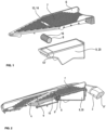
Fig. 1 in perspektivischer Ansicht von oben eine Explosionsdarstellung eines Einsatzbaugruppe zum Einsatz in einen Küchenhobel mit im Einsatz aufnehmbaren Applikator und einem Behälter, -
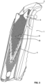
Fig. 2 in einer weiteren perspektivischen Ansicht einen erfindungsgemäßen Gemüsehobel mit dem Einsatz ausFigur 1 in einem Längsschnitt durch den Gemüsehobel, -
Figur 3 in einer weiteren perspektivischen Ansicht den inFigur 2 geschnittenen Gemüsehobel, -
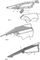
Figur 4 in einer perspektivischen Ansicht von unten die Explosionsdarstellung ausFigur 1 , -
Figur 5 in einer weiteren perspektivischen Ansicht einen Ausbruch des zusammengebauten Einsatzes gemäßFigur 1 und -
Figur 6 in einer weiteren perspektivischen Ansicht einen weiteren Längsschnitt durch den zusammengebauten Einsatz gemäßFigur 1 . - In den
Figuren 2 und3 ist ein erfindungsgemäßer Gemüsehobel 1 dargestellt. Der Küchenhobel 1 ist zum Schneiden von Schneidgut, wie Obst, Gemüse oder dergleichen geeignet. Er hat einen Grundkörper 2 mit zumindest einer in dem Grundkörper 2 gefassten Klinge 4. Er hat weiterhin eine Führungsfläche 7, auf der das Schneidgut zur Klinge 4 hin führbar ist. - Die Führungsfläche 7 ist nach dem dargestellten Ausführungsbeispiel auf einem Einsatz 6 ausgeführt, der höhenverstellbar in den Gemüsehobel 1 eingesetzt werden kann. Der Einsatz ist zur weiteren Verdeutlichung in den
Figuren 1 und4 bis 6 separat dargestellt. Die Erfindung umfasst jedoch über diese Darstellungen hinaus einen nicht dargestellten Gemüsehobel mit fest im Grundkörper integrierter Führungsfläche und ebenso integriert im Grundkörper ausgeführten weiteren erfindungswesentlichen Komponenten, wie dem nachfolgend beschriebenen Applikator. - In den
Figuren 1 bis 6 ist ein Applikator 8 gezeigt, welcher ein nicht dargestelltes Fluid mit dem ebenfalls nicht dargestellten Schneidgut in Kontakt zu bringen bestimmt ist. Mithin ist er dazu bestimmt, der Klinge 4 indirekt ein Fluid zuzuführen. Der Applikator 8 ist durch die Führungsfläche 7 hindurch wirkend in dem Küchenhobel 1 aufgenommen, vorliegend in dem Einsatz 6. - Der Applikator 8 ist bewegbar in dem Einsatz aufgenommen, nämlich rotierbar. Der dargestellte Applikator 8 ist eine nicht angetriebene, radial außen konturierte Hohlwelle und damit ein passiver Applikator. Rotierbar aufgenommen ist der Applikator vorliegend, weil von beiden axialen Seiten ein Eingriff erfolgen kann, um welchen Eingriff herum der Applikator rotieren kann. Je fester der Sitz des Applikators im Eingriff konstruiert ist, desto mehr sichere Reibung durch das herüber zu streichende Schneidgut ist erforderlich, um die Rotation zu bewirken. Rotiert der in einem Fluid laufende Applikator fördert er an seiner radial äußeren Oberfläche mitgenommenes Fluid zum Schneidgut und mit ihm zur Klinge 4.
- Zur Positionierung des Applikators 8 ist die Führungsfläche 7, und vorliegend damit auch der Einsatz 6 beabstandet zur Klinge 4 in eine die Führungsfläche 7 in Führungsrichtung des Schneidguts unterbrechende Öffnung 10 eingesetzt, nämlich in eine des Form des Applikators 8 entsprechend ausgestaltete, vorliegend rechteckige Öffnung 10. Die Öffnung 10 liegt mithin mittig in der Führungsfläche 7 des Küchenhobels 1, nämlich auf der in der Reib- oder Führungsrichtung ausgerichteten Längsachse des Küchenhobels 1. Der Abstand der Öffnung 10 zur vorliegend V-förmigen Klinge 4 beträgt etwa 1 bis 5 cm.
- Der Applikator 8 ist unterhalb der Öffnung 10 und die Öffnung 10 teilweise durchtretend in dem Einsatz 6 zerstörungsfrei lösbar aufgenommen. Der Applikator ist damit ein Austrittsende eines der Führungsfläche 7 abgewandt unterhalb des Einsatzes ebenfalls zerstörungsfreu lösbar befestigenden Behälters 20. Der Behälter 20 formt im dargestellten Ausführungsbeispiel eine Art Schöpfwanne für den rotierbaren Applikator 8.
- Der Applikator selbst (in einer nicht dargestellten Ausführungsform) oder eine vorliegend in der Öffnung 10 ausgebildete den Applikator 8 lagernde Aufnahme 14, 14` weist Haltemittel 12, 12' auf, vorliegend positiv in der Aufnahme ausgestaltete Haltemittel 12, vgl.
Fig. 4 . Es eignen sich angeschrägte Wellenstümpfe oder Zapfen, welche Haltemittel 12, 12' den Applikator 8 eine Funktion hinsichtlich der Bewegbarkeit des Applikators 8 und hinsichtlich eines Haltens des Applikators 8 in Bezug zur Führungsfläche 7 übernehmen. Die vorliegend angeschrägten Wellenstümpfe funktionieren gemeinsam als eine Achse für den rotierbaren und hohlen Applikator 8. Wegen der Schrägen ist der Applikator zwischen die Wellenstümpfe eindrückbar, bis sie in das radial Innere einspringen. - Grundsätzlich der Erfindung folgend ist / sind in dem Grundkörper 2 und/oder in dem Einsatz 6 und/oder an dem Einsatz zerstörungsfrei lösbar befestigt und/oder in dem Applikator 8 Orte vorteilhafter Ausführungsbeispiele für ein Fluidreservoir 9, 9', 9" gefunden worden. Sie konnten beispielsweise mittels eines Ventils verschlossen ausgestaltet sein (nicht dargestelltes Ausführungsbeispiel).
- Der Applikator 8 weist eine mit dem Schneidgut in Kontakt tretende Oberflächenkontur 16 auf, mit welcher die Fluidabgabemenge beeinflusst ist. Für unterschiedliche Fluide werden erfindungsgemäß ggf. unterschiedliche Konturen eingesetzt. Das Fluid ist mittels des Applikators ohne jegliche Zufuhrleitung, nämlich direkt aus einem Reservoir 9 zur Klinge 4 hin förderbar.
-
- 1
- Küchenhobel
- 2
- Grundkörper
- 4
- Klinge
- 6
- Einsatz
- 7
- Führungsfläche
- 8
- Applikator
- 9
- Reservoir
- 9'
- Reservoir
- 9"
- Reservoir
- 10
- Öffnung
- 12
- Haltemittel
- 12`
- Haltemittel
- 14
- Aufnahme
- 14'
- Aufnahme
- 16
- Oberflächenkontur
- 20
- Behälter
Claims (14)
- Küchenhobel (1) zum Schneiden von Schneidgut, wie Obst, Gemüse oder dergleichen,1.1 mit einem Grundkörper (2) und zumindest einer in dem Grundkörper (2) gefassten Klinge (4), um Stücke von dem Schneidgut abzuschneiden,1.2 mit einer Führungsfläche (7), auf der das Schneidgut zur Klinge (4) führbar ist, und1.3 mit einem Applikator (8), der dazu bestimmt ist, der Klinge (4) direkt oder indirekt ein Fluid zuzuführen,
dadurch gekennzeichnet, dass1.4 der Applikator (8) durch die Führungsfläche (7) hindurch wirkend in dem Küchenhobel (1) aufgenommen ist. - Küchenhobel (1) gemäß Anspruch 1,
dadurch gekennzeichnet, dass ein, bevorzugt höhenverstellbar im Küchenhobel (1) aufgenommener, Einsatz (6) zumindest einen Teil der Führungsflache (7) aufweist. - Küchenhobel (1) gemäß Anspruch 2,
dadurch gekennzeichnet, dass der Applikator (8) in dem Einsatz (6) aufgenommen ist, - Küchenhobel (1) gemäß einem der vorangehenden Ansprüche, dadurch gekennzeichnet, dass der Applikator (8) zumindest teilweise die Führungsflache (7) durchtretend in dem Küchenhobel (1), insbesondere in dem Einsatz (6), aufgenommen ist.
- Küchenhobel (1) gemäß einem der Ansprüche 1 oder 2, dadurch gekennzeichnet, dass der Applikator (8) bewegbar in dem Küchenhobel (1), insbesondere in dem Einsatz (6), aufgenommen ist,
- Küchenhobel (1) gemäß einem der vorangehenden Ansprüche dadurch gekennzeichnet, dass die Führungsfläche, insbesondere der Einsatz (6), an die Klinge (4) anschließend oder in einem Abstand zur Klinge (4) einer Rücknahme oder eine die Führungsfläche (7) teilweise begrenzende oder unterbrechende Öffnung (10) aufweist, insbesondere eine rechteckige Öffnung (10).
- Küchenhobel (1) gemäß Anspruch 6,
dadurch gekennzeichnet, dass die Öffnung (10) mittig, auf einer in einer Reibrichtung ausgerichteten Längsachse des Küchenhobels, in der Führungsfläche (7) angeordnet ist, bevorzugt in einem Abstand von 1 cm bis 5 cm zu der Klinge (4). - Küchenhobel (1) gemäß Anspruch 6 oder 7,
dadurch gekennzeichnet, dass der Applikator (8) unterhalb der Öffnung (10) oder die Öffnung (10) zumindest teilweise durchtretend in dem Einsatz (6) oder in einem der Führungsflache (7) abgewandt am Einsatz (6) zerstörungsfrei lösbar zu befestigenden Behälter (20) aufgenommen ist. - Küchenhobel (1) gemäß einem der vorangehenden Ansprüche, dadurch gekennzeichnet, dass der Applikator (8) oder eine den Applikator (8) lagernde Aufnahme (14, 14') Haltemittel (12, 12') aufweist, insbesondere positiv oder negativ ausgestaltete, besonders bevorzugt angeschrägte, Wellenstümpfe, welche Haltemittel (12, 12') eine Funktion hinsichtlich der Bewegbarkeit des Applikators (8) und hinsichtlich eines Haltens des Applikators (8) in Bezug zur Führungsfläche (7) übernehmen.
- Küchenhobel (1) gemäß einem der vorangehenden Ansprüche, dadurch gekennzeichnet, dass10.1 in dem Grundkörper (2) und/oder10.2 in dem Einsatz (6) und/oder10.3 an dem Einsatz zerstörungsfrei lösbar befestigt und/oder10.4 in dem Applikator (8)10.5 ein, bevorzugt mittels eines Ventils verschlossenes, Reservoir (9, 9', 9 1 ') für das Fluid angeordnet ist.
- Küchenhobel (1) gemäß einem der vorangehenden Ansprüche, dadurch gekennzeichnet, dass der Applikator (8) eine mit dem Schneidgut in Kontakt tretende Oberflächenkontur (16) und/oder ein Stellglied aufweist, mit welcher/welchem bzw. welchen die Fluidabgabemenge beeinflusst ist, bevorzugt steuerbar ist.
- Küchenhobel (1) gemäß einem der vorangehenden Ansprüche, dadurch gekennzeichnet, dass das Fluid ohne jegliche Zufuhrleitung, nämlich direkt aus einem Reservoir (9) zur Klinge (4) förderbar ist, welche Zufuhrleitung beispielsweise einen von einer Austrittsöffnung für das Fluid entfernt angeordneten Fluidvorratsbehälter mit der Austrittsöffnung verbinden würde, sondern ausschließlich mittels des, bevorzugt mit dem Schneidgut während des Schneidens in Kontakt tretenden, Applikators (8) der Klinge (4) direkt oder indirekt zugeführt wird.
- Küchenhobel (1) gemäß einem der vorangehenden Ansprüche, dadurch gekennzeichnet, dass der Applikator (8) ohne Betätigungsmittel in die Bewegung versetzbar ist.
- Küchenhobel (1) nach einem der vorangehenden Ansprüche, dadurch gekennzeichnet, dass der Applikator (8) als ein Anbauteil oder als eine auswechselbare Komponente ausgestaltet ist.
Applications Claiming Priority (2)
| Application Number | Priority Date | Filing Date | Title |
|---|---|---|---|
| DE102016001566.7A DE102016001566A1 (de) | 2016-02-12 | 2016-02-12 | Küchenhobel und Applikator |
| PCT/DE2017/000024 WO2017137024A1 (de) | 2016-02-12 | 2017-02-13 | Küchenhobel und applikator |
Publications (3)
| Publication Number | Publication Date |
|---|---|
| EP3297798A1 EP3297798A1 (de) | 2018-03-28 |
| EP3297798C0 EP3297798C0 (de) | 2024-11-06 |
| EP3297798B1 true EP3297798B1 (de) | 2024-11-06 |
Family
ID=58489444
Family Applications (1)
| Application Number | Title | Priority Date | Filing Date |
|---|---|---|---|
| EP17715893.8A Active EP3297798B1 (de) | 2016-02-12 | 2017-02-13 | Küchenhobel und applikator |
Country Status (4)
| Country | Link |
|---|---|
| US (1) | US10611044B2 (de) |
| EP (1) | EP3297798B1 (de) |
| DE (1) | DE102016001566A1 (de) |
| WO (1) | WO2017137024A1 (de) |
Families Citing this family (4)
| Publication number | Priority date | Publication date | Assignee | Title |
|---|---|---|---|---|
| CN111745700A (zh) * | 2020-06-30 | 2020-10-09 | 菏泽畅千机械设备有限公司 | 一种智能化食品生产切段机 |
| DE102023123350A1 (de) | 2023-08-30 | 2025-03-06 | Börner Distribution International GmbH | Vorrichtung zum Zerkleinern von Lebensmitteln |
| LU505030B1 (de) | 2023-08-30 | 2025-02-28 | Boerner Distribution Int Gmbh | Vorrichtung zum Zerkleinern von Lebensmitteln |
| USD1115464S1 (en) | 2023-11-14 | 2026-03-03 | Tarek R Schoner | Food slicer set |
Family Cites Families (15)
| Publication number | Priority date | Publication date | Assignee | Title |
|---|---|---|---|---|
| US4448808A (en) * | 1982-04-15 | 1984-05-15 | Gerber Garment Technology, Inc. | Method for preparing pattern piece |
| US5745999A (en) * | 1996-12-09 | 1998-05-05 | Zirkiev; Arkady | Food slicer device |
| US5765472A (en) * | 1997-02-10 | 1998-06-16 | Kim; Sun Y. | Fruit and vegetable hand slicer |
| US6941609B2 (en) * | 2003-04-16 | 2005-09-13 | James Woodruff | Paint roller assembly |
| FR2853849B1 (fr) * | 2003-04-16 | 2005-07-08 | Buyer De | Dispositif de decoupe de legumes en rubans ou en lamelles ainsi que boitier destine a un tel dispositif |
| US20040231482A1 (en) * | 2003-05-02 | 2004-11-25 | Howard Boilen | Food processing device |
| DE10328506B4 (de) * | 2003-06-18 | 2005-05-04 | Börner Kunststoff- und Metallwarenfabrik GmbH | Küchenhobel |
| US20050081690A1 (en) * | 2003-10-21 | 2005-04-21 | Biro Michael J. | Meat cutting band saw |
| FR2924009B1 (fr) * | 2007-11-26 | 2009-12-18 | Buyer Ind De | Coupe-legumes manuel permettant la decoupe de legumes en batonnets ou en cubes |
| US8430006B2 (en) * | 2008-04-25 | 2013-04-30 | Maxwell Chase Technologies, Llc | Article slicer with integral pick and placer |
| US20110280999A1 (en) * | 2009-12-23 | 2011-11-17 | Provo Craft And Novelty, Inc. | Foodstuff Crafting Apparatus, Components, Assembly, and Method for Utilizing the Same |
| US9381661B2 (en) * | 2013-10-07 | 2016-07-05 | Curt G. Joa, Inc. | Corrosion protected anvil and knife cutting assembly |
| DE102013019078A1 (de) * | 2013-11-16 | 2015-05-21 | Börner Distribution International GmbH | Verfahren zum Schneiden von Obst, Gemüse oder dergleichen, Schneidwerkzeug, Applikator zur Verwendung in einem Schneidwerkzeug |
| MX2015001335A (es) * | 2014-01-28 | 2016-04-26 | Freshway Innovation Llc | Aparato agricola para recolectar, cortar y/o procesar frutas y verduras y metodos de lo mismo. |
| EP3207841B1 (de) * | 2016-02-16 | 2019-05-08 | DKB Household UK Limited | Nahrungsmittelschieber- und nahrungsmittelhaltersysteme sowie küchenhobel damit |
-
2016
- 2016-02-12 DE DE102016001566.7A patent/DE102016001566A1/de active Pending
-
2017
- 2017-02-13 US US15/577,358 patent/US10611044B2/en active Active
- 2017-02-13 WO PCT/DE2017/000024 patent/WO2017137024A1/de not_active Ceased
- 2017-02-13 EP EP17715893.8A patent/EP3297798B1/de active Active
Also Published As
| Publication number | Publication date |
|---|---|
| WO2017137024A1 (de) | 2017-08-17 |
| DE102016001566A1 (de) | 2017-08-17 |
| EP3297798C0 (de) | 2024-11-06 |
| US20180154538A1 (en) | 2018-06-07 |
| EP3297798A1 (de) | 2018-03-28 |
| US10611044B2 (en) | 2020-04-07 |
Similar Documents
| Publication | Publication Date | Title |
|---|---|---|
| EP3297798B1 (de) | Küchenhobel und applikator | |
| DE102007042660B4 (de) | Handbetätigte Vorrichtung zum Schneiden von Lebensmitteln, insbesonder Obst und Gemüse | |
| EP1874508B1 (de) | Vorrichtung zum schneiden von früchten, insbesondere gemüse oder obst | |
| DE102013109429B3 (de) | Vorrichtung zum Einschneiden einer hartschaligen Frucht | |
| EP3068270B1 (de) | Verfahren zum schneiden von obst, gemüse oder dergleichen, schneidwerkzeug | |
| EP0717599A1 (de) | Vorrichtung zum schälen von stangenförmigem gemüse | |
| EP2386196A1 (de) | Landwirtschaftliche Vorrichtung zum Verfestigen des Bodens | |
| EP2386197A1 (de) | Landwirtschaftliche Vorrichtung zum Verfestigen des Bodens | |
| DE102005033806B4 (de) | Klemmvorrichtung zum exakten manuellen Nachschleifen von Messerklingen auf einem Schleifstein | |
| EP2682239A1 (de) | Manuelles Schneidesystem, seine Verwendung und Verfahren zur Fertigung von OP-Materialien mit Lochausschnitt | |
| DE9214288U1 (de) | Vorrichtung zum Raspeln oder Reiben von Nahrungsmitteln | |
| DE102004021959A1 (de) | Vorrichtung zum Beschnitt von Broschuren | |
| DE10017157B4 (de) | Scheibenablagevorrichtung für eine Aufschnittschneidemaschine | |
| DE19820492C1 (de) | Verfahren und Vorrichtung zum Schneiden eines Gutsstrangs in Scheiben | |
| EP1987751A1 (de) | Vorrichtung zum Schneiden von Lebensmitteln | |
| DE102012201848A1 (de) | Ananas-Schneider | |
| EP1495845B1 (de) | Rotationsschneidmesser | |
| AT16730U1 (de) | Vorrichtung zum in der Tiefe definierten Einschneiden, insbesondere einer Wurst bzw. deren Haut | |
| EP2072196B1 (de) | Gleitstangenführung für Schneidmaschine | |
| DE597854C (de) | Vorrichtung zum Aufschneiden, insbesondere von Konservenbuechsen | |
| DE202007008380U1 (de) | Vorrichtung zum Schneiden von Obst, Gemüse o.dgl. | |
| DE102008033379A1 (de) | Lebensmittel-Schneidemaschine | |
| DE4030848C2 (de) | ||
| DE102013114866A1 (de) | Rundmesser sowie Messerwerkzeug mit einem Rundmesser | |
| DE105804C (de) |
Legal Events
| Date | Code | Title | Description |
|---|---|---|---|
| STAA | Information on the status of an ep patent application or granted ep patent |
Free format text: STATUS: UNKNOWN |
|
| STAA | Information on the status of an ep patent application or granted ep patent |
Free format text: STATUS: THE INTERNATIONAL PUBLICATION HAS BEEN MADE |
|
| PUAI | Public reference made under article 153(3) epc to a published international application that has entered the european phase |
Free format text: ORIGINAL CODE: 0009012 |
|
| STAA | Information on the status of an ep patent application or granted ep patent |
Free format text: STATUS: REQUEST FOR EXAMINATION WAS MADE |
|
| 17P | Request for examination filed |
Effective date: 20171220 |
|
| AK | Designated contracting states |
Kind code of ref document: A1 Designated state(s): AL AT BE BG CH CY CZ DE DK EE ES FI FR GB GR HR HU IE IS IT LI LT LU LV MC MK MT NL NO PL PT RO RS SE SI SK SM TR |
|
| AX | Request for extension of the european patent |
Extension state: BA ME |
|
| DAV | Request for validation of the european patent (deleted) | ||
| DAX | Request for extension of the european patent (deleted) | ||
| STAA | Information on the status of an ep patent application or granted ep patent |
Free format text: STATUS: EXAMINATION IS IN PROGRESS |
|
| 17Q | First examination report despatched |
Effective date: 20210521 |
|
| GRAP | Despatch of communication of intention to grant a patent |
Free format text: ORIGINAL CODE: EPIDOSNIGR1 |
|
| STAA | Information on the status of an ep patent application or granted ep patent |
Free format text: STATUS: GRANT OF PATENT IS INTENDED |
|
| INTG | Intention to grant announced |
Effective date: 20240305 |
|
| GRAS | Grant fee paid |
Free format text: ORIGINAL CODE: EPIDOSNIGR3 |
|
| GRAJ | Information related to disapproval of communication of intention to grant by the applicant or resumption of examination proceedings by the epo deleted |
Free format text: ORIGINAL CODE: EPIDOSDIGR1 |
|
| GRAL | Information related to payment of fee for publishing/printing deleted |
Free format text: ORIGINAL CODE: EPIDOSDIGR3 |
|
| STAA | Information on the status of an ep patent application or granted ep patent |
Free format text: STATUS: EXAMINATION IS IN PROGRESS |
|
| GRAP | Despatch of communication of intention to grant a patent |
Free format text: ORIGINAL CODE: EPIDOSNIGR1 |
|
| STAA | Information on the status of an ep patent application or granted ep patent |
Free format text: STATUS: GRANT OF PATENT IS INTENDED |
|
| INTC | Intention to grant announced (deleted) | ||
| INTG | Intention to grant announced |
Effective date: 20240731 |
|
| RAP3 | Party data changed (applicant data changed or rights of an application transferred) |
Owner name: BOERNER DISTRIBUTION INTERNATIONAL GMBH |
|
| GRAA | (expected) grant |
Free format text: ORIGINAL CODE: 0009210 |
|
| STAA | Information on the status of an ep patent application or granted ep patent |
Free format text: STATUS: THE PATENT HAS BEEN GRANTED |
|
| AK | Designated contracting states |
Kind code of ref document: B1 Designated state(s): AL AT BE BG CH CY CZ DE DK EE ES FI FR GB GR HR HU IE IS IT LI LT LU LV MC MK MT NL NO PL PT RO RS SE SI SK SM TR |
|
| REG | Reference to a national code |
Ref country code: GB Ref legal event code: FG4D Free format text: NOT ENGLISH |
|
| REG | Reference to a national code |
Ref country code: CH Ref legal event code: EP |
|
| REG | Reference to a national code |
Ref country code: DE Ref legal event code: R096 Ref document number: 502017016545 Country of ref document: DE |
|
| REG | Reference to a national code |
Ref country code: IE Ref legal event code: FG4D Free format text: LANGUAGE OF EP DOCUMENT: GERMAN |
|
| U01 | Request for unitary effect filed |
Effective date: 20241206 |
|
| U07 | Unitary effect registered |
Designated state(s): AT BE BG DE DK EE FI FR IT LT LU LV MT NL PT RO SE SI Effective date: 20241217 |
|
| U20 | Renewal fee for the european patent with unitary effect paid |
Year of fee payment: 9 Effective date: 20250210 |
|
| PG25 | Lapsed in a contracting state [announced via postgrant information from national office to epo] |
Ref country code: IS Free format text: LAPSE BECAUSE OF FAILURE TO SUBMIT A TRANSLATION OF THE DESCRIPTION OR TO PAY THE FEE WITHIN THE PRESCRIBED TIME-LIMIT Effective date: 20250306 Ref country code: HR Free format text: LAPSE BECAUSE OF FAILURE TO SUBMIT A TRANSLATION OF THE DESCRIPTION OR TO PAY THE FEE WITHIN THE PRESCRIBED TIME-LIMIT Effective date: 20241106 |
|
| PG25 | Lapsed in a contracting state [announced via postgrant information from national office to epo] |
Ref country code: ES Free format text: LAPSE BECAUSE OF FAILURE TO SUBMIT A TRANSLATION OF THE DESCRIPTION OR TO PAY THE FEE WITHIN THE PRESCRIBED TIME-LIMIT Effective date: 20241106 |
|
| PG25 | Lapsed in a contracting state [announced via postgrant information from national office to epo] |
Ref country code: NO Free format text: LAPSE BECAUSE OF FAILURE TO SUBMIT A TRANSLATION OF THE DESCRIPTION OR TO PAY THE FEE WITHIN THE PRESCRIBED TIME-LIMIT Effective date: 20250206 |
|
| PG25 | Lapsed in a contracting state [announced via postgrant information from national office to epo] |
Ref country code: GR Free format text: LAPSE BECAUSE OF FAILURE TO SUBMIT A TRANSLATION OF THE DESCRIPTION OR TO PAY THE FEE WITHIN THE PRESCRIBED TIME-LIMIT Effective date: 20250207 |
|
| PG25 | Lapsed in a contracting state [announced via postgrant information from national office to epo] |
Ref country code: PL Free format text: LAPSE BECAUSE OF FAILURE TO SUBMIT A TRANSLATION OF THE DESCRIPTION OR TO PAY THE FEE WITHIN THE PRESCRIBED TIME-LIMIT Effective date: 20241106 |
|
| PG25 | Lapsed in a contracting state [announced via postgrant information from national office to epo] |
Ref country code: RS Free format text: LAPSE BECAUSE OF FAILURE TO SUBMIT A TRANSLATION OF THE DESCRIPTION OR TO PAY THE FEE WITHIN THE PRESCRIBED TIME-LIMIT Effective date: 20250206 |
|
| PG25 | Lapsed in a contracting state [announced via postgrant information from national office to epo] |
Ref country code: SM Free format text: LAPSE BECAUSE OF FAILURE TO SUBMIT A TRANSLATION OF THE DESCRIPTION OR TO PAY THE FEE WITHIN THE PRESCRIBED TIME-LIMIT Effective date: 20241106 |
|
| PG25 | Lapsed in a contracting state [announced via postgrant information from national office to epo] |
Ref country code: SK Free format text: LAPSE BECAUSE OF FAILURE TO SUBMIT A TRANSLATION OF THE DESCRIPTION OR TO PAY THE FEE WITHIN THE PRESCRIBED TIME-LIMIT Effective date: 20241106 |
|
| PG25 | Lapsed in a contracting state [announced via postgrant information from national office to epo] |
Ref country code: CZ Free format text: LAPSE BECAUSE OF FAILURE TO SUBMIT A TRANSLATION OF THE DESCRIPTION OR TO PAY THE FEE WITHIN THE PRESCRIBED TIME-LIMIT Effective date: 20241106 |
|
| PLBE | No opposition filed within time limit |
Free format text: ORIGINAL CODE: 0009261 |
|
| STAA | Information on the status of an ep patent application or granted ep patent |
Free format text: STATUS: NO OPPOSITION FILED WITHIN TIME LIMIT |
|
| PG25 | Lapsed in a contracting state [announced via postgrant information from national office to epo] |
Ref country code: MC Free format text: LAPSE BECAUSE OF FAILURE TO SUBMIT A TRANSLATION OF THE DESCRIPTION OR TO PAY THE FEE WITHIN THE PRESCRIBED TIME-LIMIT Effective date: 20241106 |
|
| REG | Reference to a national code |
Ref country code: CH Ref legal event code: PL |
|
| 26N | No opposition filed |
Effective date: 20250807 |
|
| PG25 | Lapsed in a contracting state [announced via postgrant information from national office to epo] |
Ref country code: CH Free format text: LAPSE BECAUSE OF NON-PAYMENT OF DUE FEES Effective date: 20250228 |
|
| GBPC | Gb: european patent ceased through non-payment of renewal fee |
Effective date: 20250213 |
|
| PG25 | Lapsed in a contracting state [announced via postgrant information from national office to epo] |
Ref country code: GB Free format text: LAPSE BECAUSE OF NON-PAYMENT OF DUE FEES Effective date: 20250213 |
|
| PG25 | Lapsed in a contracting state [announced via postgrant information from national office to epo] |
Ref country code: IE Free format text: LAPSE BECAUSE OF NON-PAYMENT OF DUE FEES Effective date: 20250213 |