EP3296476B1 - Anordnung zum verbinden einer gebäudewand mit einer boden- oder deckenplatte und formbaustein für eine solche anordnung - Google Patents
Anordnung zum verbinden einer gebäudewand mit einer boden- oder deckenplatte und formbaustein für eine solche anordnung Download PDFInfo
- Publication number
- EP3296476B1 EP3296476B1 EP16189204.7A EP16189204A EP3296476B1 EP 3296476 B1 EP3296476 B1 EP 3296476B1 EP 16189204 A EP16189204 A EP 16189204A EP 3296476 B1 EP3296476 B1 EP 3296476B1
- Authority
- EP
- European Patent Office
- Prior art keywords
- molded
- building
- floor
- building wall
- wall
- Prior art date
- Legal status (The legal status is an assumption and is not a legal conclusion. Google has not performed a legal analysis and makes no representation as to the accuracy of the status listed.)
- Active
Links
Images


Classifications
-
- E—FIXED CONSTRUCTIONS
- E04—BUILDING
- E04B—GENERAL BUILDING CONSTRUCTIONS; WALLS, e.g. PARTITIONS; ROOFS; FLOORS; CEILINGS; INSULATION OR OTHER PROTECTION OF BUILDINGS
- E04B1/00—Constructions in general; Structures which are not restricted either to walls, e.g. partitions, or floors or ceilings or roofs
- E04B1/62—Insulation or other protection; Elements or use of specified material therefor
- E04B1/74—Heat, sound or noise insulation, absorption, or reflection; Other building methods affording favourable thermal or acoustical conditions, e.g. accumulating of heat within walls
- E04B1/76—Heat, sound or noise insulation, absorption, or reflection; Other building methods affording favourable thermal or acoustical conditions, e.g. accumulating of heat within walls specifically with respect to heat only
- E04B1/78—Heat insulating elements
-
- E—FIXED CONSTRUCTIONS
- E04—BUILDING
- E04C—STRUCTURAL ELEMENTS; BUILDING MATERIALS
- E04C1/00—Building elements of block or other shape for the construction of parts of buildings
- E04C1/40—Building elements of block or other shape for the construction of parts of buildings built-up from parts of different materials, e.g. composed of layers of different materials or stones with filling material or with insulating inserts
- E04C1/41—Building elements of block or other shape for the construction of parts of buildings built-up from parts of different materials, e.g. composed of layers of different materials or stones with filling material or with insulating inserts composed of insulating material and load-bearing concrete, stone or stone-like material
-
- E—FIXED CONSTRUCTIONS
- E04—BUILDING
- E04B—GENERAL BUILDING CONSTRUCTIONS; WALLS, e.g. PARTITIONS; ROOFS; FLOORS; CEILINGS; INSULATION OR OTHER PROTECTION OF BUILDINGS
- E04B1/00—Constructions in general; Structures which are not restricted either to walls, e.g. partitions, or floors or ceilings or roofs
- E04B1/62—Insulation or other protection; Elements or use of specified material therefor
- E04B1/74—Heat, sound or noise insulation, absorption, or reflection; Other building methods affording favourable thermal or acoustical conditions, e.g. accumulating of heat within walls
- E04B1/76—Heat, sound or noise insulation, absorption, or reflection; Other building methods affording favourable thermal or acoustical conditions, e.g. accumulating of heat within walls specifically with respect to heat only
- E04B2001/7679—Means preventing cold bridging at the junction of an exterior wall with an interior wall or a floor
-
- E—FIXED CONSTRUCTIONS
- E04—BUILDING
- E04B—GENERAL BUILDING CONSTRUCTIONS; WALLS, e.g. PARTITIONS; ROOFS; FLOORS; CEILINGS; INSULATION OR OTHER PROTECTION OF BUILDINGS
- E04B2/00—Walls, e.g. partitions, for buildings; Wall construction with regard to insulation; Connections specially adapted to walls
- E04B2/02—Walls, e.g. partitions, for buildings; Wall construction with regard to insulation; Connections specially adapted to walls built-up from layers of building elements
- E04B2002/0256—Special features of building elements
- E04B2002/028—Spacers between building elements
- E04B2002/0284—Spacers between building elements forming a unity with the building elements
Definitions
- the invention relates to an arrangement for connecting a substantially vertical building wall, in particular a load-bearing wall, to a floor or ceiling slab and for forming a wall connection system. Furthermore, a molded component for arranging between a building wall and a floor or ceiling slab, for supporting the building wall on the floor or ceiling slab or for supporting the ceiling slab on the building wall, is described.
- Arrangements for connecting a building wall to a floor or ceiling slab are known, which as wall connection systems create a connection between a preferably cast vertical concrete wall and a horizontal floor or ceiling slab arranged underneath and transmit compressive forces in a vertical direction.
- arrangements known from the prior art are intended to achieve the greatest possible thermal decoupling between a floor slab and a building wall arranged on it, in particular a cast concrete wall.
- an arrangement for connecting a building wall to a floor or ceiling slab which has a pressure-transmitting and insulating connection element for connecting two cast components with an insulating body for thermal separation of the components.
- the insulating body has one or more pressure elements made of a concrete material that penetrate the upper and lower support surface of the insulating body.
- the pressure elements are arranged at intervals from one another within the insulating body, which is predominantly made of an insulating material, with the spaces between the pressure elements being filled with the insulating material.
- connection elements known from the prior art However, they have the disadvantage that shear forces, i.e. forces that act in the longitudinal direction of the wall, can only be absorbed to a limited extent and introduced into the floor or ceiling slab below.
- Another disadvantage of the state of the art is the same load deformation behavior of the connecting elements, which means that deformation and force transmission are not decoupled. This can lead to an uneven distribution of force along the building wall and possibly an uneven expansion of the wall in its longitudinal direction.
- AT 002 799 U1 reveals a ceiling formwork block with integrated thermal insulation, which forms the ceiling formwork after bricklaying.
- DE 200 08 570 U1 discloses a brick-shaped thermal insulation element for thermal decoupling between wall parts and floor/ceiling panels, consisting of at least one pressure-resistant support element and at least one thermally insulating element, wherein the thermal insulation element has at least one anchoring projection on its outer side, which serves for the positive connection to the adjacent wall part.
- the present invention is based on the object of addressing one of the problems mentioned.
- at least one alternative to the known arrangements is to be created.
- the invention takes into account the fact that, particularly in the case of long building walls, mechanical stresses can arise between the building wall and a floor or ceiling slab due to different expansions, which are particularly thermally caused.
- at least one sliding bearing component is provided.
- At least one molded component is designed as a sliding bearing component and has a surface property on a support surface and/or a bearing surface to allow a relative movement between the molded component and the building wall or the floor or ceiling slab.
- Such a sliding bearing module transfers vertical forces from the building wall to the ceiling or floor slab, or vice versa, but allows compensating movements in the longitudinal direction of the wall. At least it transfers comparatively little force in the longitudinal direction of the wall.
- the sliding bearing module is adapted accordingly in a connection area or contact area.
- the connection area or contact area is the one in which the shaped module comes into contact with the building wall and/or the floor or ceiling slab and via which vertical forces are transferred between the shaped module and the building wall or the floor or ceiling slab.
- the compensating movement is permitted in this connection area or contact area.
- the contact surface and/or the bearing surface can form the connection area.
- At least one fixed bearing block is provided to fix the wall relative to the floor or ceiling slab, or vice versa.
- a fixed bearing block transfers vertical forces from the building wall to the ceiling or floor slab, or vice versa, without allowing compensating movements in the longitudinal direction of the wall.
- the fixed bearing block can also be used in a connecting section or contact area be designed accordingly, namely by not allowing any compensating movements there, but rather by being able to transfer shear forces, in particular high shear forces in the longitudinal direction of the building wall. This particularly applies to high shear forces such as those that typically occur in building stabilization.
- the contact surface and/or the support surface can form the connecting section.
- One way to design the contact surface and/or the support surface of the fixed bearing component is to design it in such a way that a positive connection is achieved.
- a toothed joint which can also be referred to as a wave profile, can be provided. This can achieve a firm connection, or at least a good transmission of the thrust forces.
- the arrangement according to the invention has at least two, preferably more than two, molded blocks and thus forms a wall connection system. This is used to specifically influence the relative movement or possible relative movement between different parts of the building, namely a floor or ceiling slab and a building wall.
- At least one fixed bearing module supports and thus fixes the building wall in at least one fixed bearing section or fixed bearing area on the floor or ceiling slab, while at least one sliding bearing module supports the building wall in at least one sliding bearing section or sliding bearing area without fixing it, at least without fixing it as firmly as the fixed bearing module.
- the shaped modules it is also possible for the shaped modules to be arranged on the building wall and under a floor or ceiling slab.
- the shear spring stiffness of the fixed bearing blocks is significantly higher, in particular at least 50% higher than the shear strength of the plain bearing blocks This prevents relative movement between the building wall and the floor or ceiling slab, at least along this fixed bearing section of the building wall. Shear forces acting in the longitudinal direction of the concrete wall are absorbed by the fixed bearing module and largely transferred to the floor or ceiling slab.
- a shaped module designed as a sliding bearing module enables relative movement of the building wall without significant force transfer in the longitudinal direction of the building wall.
- Both the fixed bearing block and the sliding bearing block are designed as molded blocks.
- a molded block is understood here to be a type of stone that is artificially manufactured and preferably consists of one piece or is formed in one piece, whereby it can contain additional elements, such as an insulating element.
- the molded block consists of a one-piece cast molded piece that defines at least the external dimensions of the molded block.
- the molded block can be cast from concrete, which then hardens to form the molded block.
- the molded blocks are arranged in a row and this row is divided into at least one fixed bearing area and at least one sliding bearing area, each fixed bearing area having at least one fixed bearing block and each sliding bearing area having at least one sliding bearing block.
- sliding bearing areas and fixed bearing areas different sections of the building wall can be provided.
- the number and position of the fixed bearing areas and also the length of a respective fixed bearing area in which the building wall is firmly connected to the floor or ceiling slab can be individually adapted.
- Each fixed bearing area has at least one, two, three or more fixed bearing blocks, via which the firm connection in which the shear forces are transmitted is ensured.
- each sliding bearing area has one, two, three or more sliding bearing blocks. This division of the areas can be adapted to the expected expansion behavior as well as the actual shear force distribution, especially of the building wall.
- a fixed bearing area or the bearing area is arranged at at least one end of the arrangement and a sliding bearing area or the bearing area is arranged in a middle area, with a fixed bearing area being arranged at both ends of the arrangement and a sliding bearing area in between.
- an arrangement according to the invention for connecting the Building wall with the floor or ceiling slab below or above it is advantageous.
- the sliding bearing modules in the sliding bearing area can ensure that possible changes in the length of the building wall and the associated shear forces in the longitudinal direction of the building wall, caused by changes in ambient temperature, are balanced out or distributed across the sliding bearing area. This enables a uniform longitudinal displacement of the corresponding section of the building wall to be implemented along the sliding bearing area.
- a or the sliding bearing region is arranged at at least one end of the arrangement and a or the fixed bearing region is arranged in a central region, wherein in particular a sliding bearing region is arranged at each of the two ends of the arrangement and the fixed bearing region is arranged in between.
- This central area or middle area of the building wall is thus firmly connected to the floor or ceiling slab below or the ceiling slab above via one or more fixed bearing blocks.
- a sliding bearing area with one, two or more sliding bearing blocks is arranged on both sides of the fixed bearing area.
- compressive forces arising within the building wall are then reduced on both sides of a fixed bearing area that transmits and/or absorbs shear forces.
- This embodiment is particularly recommended for building walls less than 10 m long, preferably less than 7 m.
- the molded blocks are arranged in such a way that adjacent molded blocks touch each other.
- the molded blocks are arranged at a distance from each other.
- similar molded blocks for example several fixed bearing blocks, are preferably arranged touching each other and unequal molded blocks, for example a fixed bearing block and a sliding bearing block arranged next to it, are arranged at a distance from each other.
- molded blocks, fixed bearing blocks or sliding bearing blocks are arranged touching each other or at a distance from each other.
- the distance between the molded blocks at the end areas of the building wall is chosen to be smaller than the distance in the area of the shear center (SM) of the building wall. This means that, due to movements of the building, At the ends of the building wall, essentially vertically acting tensile and compressive forces are safely absorbed.
- SM shear center
- the fixed bearing module has a connecting section at least on its support surface supporting the building wall, which is designed to absorb the shear forces acting in the longitudinal direction of the wall and to transfer them to the floor or ceiling slab underneath.
- the fixed bearing module preferably has a connecting section on its support surface and its contact surface for absorbing and transferring shear forces acting in the longitudinal direction of the wall. The reverse case is therefore also possible, in which shear forces from a floor or ceiling slab supported above the building wall are introduced into the building wall via the connecting section, or shear forces are introduced upwards from the building wall into the floor or ceiling slab.
- Shear forces which are directed lengthways to the building wall, are introduced into the fixed bearing block via the connecting section.
- This connecting section which can also be referred to as the contact area, is designed in such a way that it prevents movement between the building wall and the fixed bearing block.
- a rough, highly abrasive or adhesive surface can be provided in the connecting section. This can be achieved by sanding or graveling the support and contact surface of the fixed bearing block.
- Profiling transverse to the direction of shear or a wedge-shaped profile, similar to a herringbone pattern, can also be considered, to name further examples.
- the sliding bearing module has a sliding section at least on its support surface supporting the building wall, the sliding section being designed to allow the movements of the wall relative to the floor or ceiling plate in the longitudinal direction of the wall.
- the sliding section has a surface with low friction, i.e. with a small friction constant, in order to ensure a low-friction movement between the surfaces of the sliding bearing module and the building wall or the sliding bearing module and the floor or ceiling plate.
- the sliding section is designed as a guide section that not only allows a compensating movement, but also guides this in the longitudinal direction of the building wall.
- a guide profile can be provided, which can be provided as an additional element, or can be integrated into the It can also be provided as a negative in a mold for casting the molded block.
- the sliding bearing module has a sliding section on its support surface supporting the building wall or a ceiling panel arranged above it and on its contact surface facing the floor or ceiling panel.
- the sliding section is preferably designed as a very smooth surface on the support surface and/or the contact surface of the sliding bearing module.
- a sliding film or a sliding sheet or an elastomer applied to the support surface and/or contact surface of the sliding bearing module is used as the sliding section.
- the molded blocks are made at least predominantly from concrete material, preferably from ultra-high-strength fiber concrete.
- the part of the molded block that does not relate to the insulation is essentially made of concrete. This makes it possible to achieve a high level of strength in the molded blocks.
- the molded blocks designed as sliding bearing blocks and fixed bearing blocks can safely absorb vertical compressive forces that result at least from the mass of the building wall standing on the arrangement according to the invention.
- shear forces acting transversely or at an oblique angle to the support surface and/or contact surface in the molded block can also be absorbed and introduced into a floor or ceiling slab.
- the fiber concrete used preferably has steel fibers with a diameter of 0.1 to 0.3 mm, preferably 0.16 to 0.24 mm.
- a molded block designed as a fixed bearing block has a higher mass fraction of concrete material than a sliding bearing block, in particular in the case of the same external dimensions of both molded blocks, the fixed bearing block has a higher absolute mass.
- the molded blocks are interspersed with reinforcement.
- the reinforcement preferably extends approximately transversely or perpendicularly to a support surface and a contact surface of a molded block.
- the reinforcement extends from a building wall through a fixed bearing block into an underlying floor or ceiling slab, or vice versa from a floor or ceiling slab through the fixed bearing block into a building wall arranged underneath.
- the building wall is preferably designed as a concrete wall. This creates the connection between the Floor or ceiling slab and the fixed bearing module and a building wall that is to be placed on top of it, for example, is improved, preferably in a vertical direction.
- a molded module designed as a sliding bearing module is interspersed with reinforcement that extends through the contact surface or through the support surface of the molded module.
- a molded module designed as a sliding bearing module has a connection to a floor or ceiling slab arranged underneath it or a building wall arranged above it or a ceiling slab arranged above it or a building wall arranged below it.
- at least the contact surface or the support surface of a sliding bearing module remains completely unconnected to a building wall arranged above it or to the floor or ceiling slab underneath it.
- the molded component comprises a molded body made of concrete material, which has a support surface facing the floor or ceiling slab and a support surface running essentially parallel thereto and facing the load-bearing building wall, wherein the molded body has a plurality of insulation body sections running essentially parallel to and between the support and support surface.
- a preformed block is therefore proposed that has a base body made of concrete that is interspersed with insulating body sections.
- This base body which is called the preformed body here, forms the part of the preformed block that transfers forces between the building wall and the floor or ceiling slab.
- a concrete material is proposed for this.
- the contact surface and the support surface are therefore made of concrete.
- the insulating body sections are intended for thermal insulation.
- the base body or molded body gives the molded block its supporting structure. This is why the term molded block is also used because the concrete part has the properties of a stone or building block, or is generally considered a stone, and preferably at the same time gives the shape.
- the molded block, or at least the molded body has a cuboid shape.
- the shape of the molded body corresponds to the shape of the molded block.
- the molded block can have additional elements and/or an additional layer and may then deviate slightly from the shape of the molded body.
- the insulating body sections that are located between the contact surface and the support surface are generally incorporated into the concrete mold body in such a way that they do not determine the shape of the molded block.
- other shapes can also be considered, such as a shape with at least two sides that converge, although these are not the contact surface and the support surface, which should run parallel to each other.
- the molded block is preferably designed as a fixed bearing block or as a sliding bearing block.
- a fixed bearing block is designed to absorb shear forces acting in the longitudinal direction of the wall and in particular to fix the building wall relative to the floor and/or ceiling slab.
- a sliding bearing block enables a relative movement in the longitudinal direction of the wall between the building wall and the floor or ceiling slab.
- a molded block is understood to be a type of stone that is artificially produced and preferably consists of one piece or is formed in one piece.
- the molded body made of concrete material preferably defines the external dimensions of the molded block.
- An insulating body section can, for example, be an insulating body that extends through the molded body. Several of these can be provided, which can be arranged parallel to one another or can cross one another, to name just two examples. Several insulating body sections can be designed as several insulating bodies, or as a continuous insulating body. It is also possible that the several insulating body sections are arranged or connected to one another in one embodiment in such a way that a single insulating body with a uniform shape is formed. In another embodiment of the invention, the several insulating body sections are arranged in such a way that they form several separate insulating bodies within the molded component.
- the insulating body sections extend through the molded body from one side surface to the opposite side surface of the molded block.
- the insulating body sections therefore preferably extend at least in one of the main directions over the entire width or length of the molded block, whereby the heat transfer through the molded block from its contact surface in the direction of the support surface is further reduced.
- the molded body preferably has first side surfaces that run parallel to one another and preferably transversely to the first side surfaces and second side surfaces that run parallel to one another. The first and second side surfaces therefore form a rectangle in a plan view.
- n insulating body sections penetrate the molded component approximately transversely to the first side surfaces and m insulating body sections penetrate the molded component approximately transversely to the second side surfaces.
- the insulating body sections therefore form a grid pattern in a plan view, it also being possible for only one insulating body section to be provided in at least one direction.
- n is not equal to m, so that different numbers of insulating body sections are provided in the two directions.
- two or more insulating body sections run between the first and second side surfaces of the molded component.
- the insulating body sections run at the same height between the contact surface and the support surface of the molded block and thereby form a grid structure.
- the insulating body sections run at different heights or levels between the contact surface and the support surface of the molded block.
- the multiple insulating body sections running transversely to one another run at different heights or levels within the molded block, with the insulating body sections not touching one another in one possible embodiment.
- the insulating body sections run essentially transversely to one another and cross one another to thereby form a grid or cross structure. This allows them to form an insulating matrix within the molded body.
- the insulating body sections are preferably connected to one another in such a way that each insulating body section is part of the insulating matrix.
- the insulating matrix has any number of n insulating body sections and any number of m insulating body sections.
- an insulating matrix with 4x3, 6x3 or 8x3 insulating body sections is provided.
- Such an insulating matrix made up of several insulating bodies can also be manufactured as a unit and can also be formed in one piece.
- the insulating body sections have a cylindrical shape, in particular with a substantially oval or elliptical cross-section.
- the shape of the insulating body sections simultaneously determines the inner shape of the molded body.
- the molded body Due to its resulting shape, it can easily absorb high vertical compressive forces and, if necessary, oblique shear forces and transfer them through the molded block into an underlying floor or ceiling slab and vice versa.
- the shape of the insulating body sections therefore has a direct or indirect influence on the insulating properties and the mechanical properties of the molded block.
- the proposed shape creates good insulating properties and, at the same time, good mechanical properties.
- one embodiment of the invention provides for the cross-section of the insulating body sections to be reduced or increased in the direction of extension. This allows specific areas of the molded body that are exposed to higher compressive forces and/or shear forces to be specifically reinforced. In the areas that are subject to less stress, the insulating body sections can have correspondingly larger diameters, so that the insulating behavior of the molded component is improved in these areas.
- the oval or elliptical cross-section preferably runs with its main axis approximately perpendicular to the support surface and with its minor axis parallel to the support surface.
- the elliptical cross-section is formed within the mold block in such a way that the distance between the vertices on the main axis, which preferably runs transversely to the contact or support surface of the molded body, is greater than the distance between the vertices on the minor axis.
- the surface area between the two main vertices of the cross-section has the shape or course similar to a catenary, whereby the insulating body sections have increased inherent strength in the direction of the vertically acting compressive forces.
- the resulting shape of the molded body in particular can therefore absorb and transmit forces very well.
- the catenary runs in the direction of a main axis of the insulating body section.
- the insulating body sections are designed and arranged in relation to one another in such a way that a support structure, in particular a vaulted structure, made of concrete material and filled with the insulating body sections is formed inside the molded body.
- a molded body can be produced in such a way that concrete is poured into a mold around an insulating body structure. If this insulating structure were to be removed again after the concrete had hardened, which is only done here for the purpose of illustration, described, a cavity would remain. According to one embodiment, this cavity is designed as a support structure, particularly as a vaulted structure, and because the insulation structure is not to be removed, this support structure or vaulted structure is filled with the insulation structure.
- the molded body can in principle also be manufactured in a different way. However, it is also possible that the molded body is manufactured in a different way than by pouring the concrete as described.
- This support structure or vaulted structure is therefore a cavity in which a ceiling and a floor are supported against each other at many points by column-like support sections.
- the column-like support sections are created in the areas between insulating body sections. Forces can be transmitted via this.
- the ceiling and floor of this cavity are preferably arched and each merge continuously into the respective column-like support sections. This also makes it easy to transmit transverse forces that are not perpendicular to the ceiling and floor.
- the insulating body sections form or fill channels within the mold body, which together form the cavity. Between these channels, several connecting areas made of concrete material are formed, which support the ceiling and the floor of the cavity and thus the contact surface and the support surface against each other. The connecting areas thus form a support structure between the individual insulating body sections. In addition to the connecting areas on the inside, the contact surface and the support surface are also connected to each other on the side surfaces of the mold block via visible connecting areas made of concrete material.
- a support structure as described above has several support pillars, which can also be referred to as support columns, and which extend essentially transversely, in particular perpendicularly, to the contact or support surface of the molded body.
- the support pillars extending inside and along the side surfaces of the molded block transversely to the contact or support surface of the molded body ensure good force transmission of, for example, vertical compressive forces or shear forces acting obliquely at an angle to the contact or support surface.
- the support pillars have a constant or changing cross-section in the longitudinal direction, i.e. over their length.
- the support pillars form several rows of one behind the other or next to the other in the main directions of the plane running between the contact surface and the support surface, within which the insulation matrix is arranged, i.e. in the cavity described as an example.
- the connecting areas visible from the outside on the side surfaces of the molded block also form such rows of support pillars. This can also be specified by the insulating body sections.
- the molded body has a profile element protruding from it on at least its support surface for the building wall as a connecting section with the building wall or a sliding section for the building wall.
- a connecting section formed in particular on the support surface and the contact surface, an area of the contact or support surface is designed to absorb shear forces acting parallel to the support surface and/or contact surface and to introduce them into the molded block.
- a molded block designed in particular as a fixed bearing block has at least one profile element protruding from the support surface and/or the contact surface of the molded body as a connecting section. The profile element thus creates a connection between an attached wall, floor or ceiling panel and the molded block, in particular the molded body.
- a building wall to be built on the support surface or a floor or ceiling panel brought into contact with the contact surface is fixed relative to the molded block by means of the profile element.
- the molded block preferably has a sliding section on its support surface for the building wall to be placed on it and also or alternatively a sliding section on the support surface for the floor and/or ceiling slab arranged underneath.
- the support surface or the support surface is preferably equipped with a very smooth surface so that the building wall or the floor or ceiling slab can slide relative to the molded block, which at least allows a relative movement there.
- the profile element is designed as a material projection on at least the support surface on the molded body or as a separate component which is arranged at least on the support surface.
- the profile element is designed as one piece with the molded body, whereby the profile element is also made of concrete material.
- the molded body forms a base surface on the support or support surface, which is determined by the external dimensions of the molded body, in particular its side lengths a and b. The surface area of the base surface results from the product of a*b.
- the profile element has protruding, raised surface areas on the base surface of the support or support surface.
- the profile element has a Base area, wherein the base area of the profile element or the sum of the base areas of all profile elements of the support or bearing surface, if several profile elements are formed, is less than 50% of the base area, in particular less than 45% of the base area and preferably amounts to about 40% of the base area.
- the surface areas around the raised or protruding surface areas of the profile element, including any areas in between, are thus in total larger than the base area of the profile element or the sum of the base areas, preferably they are larger than 50% of the size of the base area of the support or bearing surface, in particular larger than 55%, preferably they have about 60% of the base area.
- the profile element is a single profile element or there are several profile elements arranged at a distance from one another, which preferably protrudes transversely to the direction of extension of the building wall to be erected in the form of a toothed joint on the bearing surface and/or on the contact surface of the molded block.
- a single profile element can, for example, also be a profile area made up of several projections and depressions on the support surface and/or the contact surface, e.g. in the form of a wave profile.
- the profile element can also be designed as a separate component which is connected to the molded body of the molded block to form the connecting section with the molded block.
- the molded body which is preferably cuboid-shaped, can have such a profiled surface on its support surface and/or contact surface.
- a profile element designed as a separate component can, for example, be a rail body which is inserted into a recess formed on the support and/or contact surface.
- the rail body can have any profile in cross section.
- the concrete material is a high-strength concrete or high-strength lightweight concrete, in particular an ultra-high-strength fiber concrete, by means of which the strength of the molded block is ensured.
- the molded body is thus made from one of these materials.
- an ultra-high-strength fiber concrete with steel fibers is used, with steel fibers with a diameter of preferably 0.1 to 0.3 mm, particularly preferably 0.16 to 0.24 mm, being contained in the concrete material.
- the molded blocks have the same external dimensions, depending on their application, i.e. whether the molded block is used as a fixed bearing block or as a sliding bearing block. preferably have different mass proportions of concrete material.
- the volume proportion of the insulating body can be lower in a fixed bearing component than in a sliding bearing component.
- the molded block is designed as a sliding bearing block and has a surface property on the contact surface and/or the support surface to allow a relative movement between the molded block and the building wall or the floor or ceiling slab.
- This makes it possible to create a sliding bearing block for use in an arrangement according to the invention, particularly as described above in connection with at least one embodiment thereof.
- the effects described above for sliding bearing blocks can be achieved.
- the molded block can be designed as a fixed bearing block and have a surface property on the contact surface and/or the support surface for transmitting a shear force between the molded block and the building wall or the floor or ceiling slab.
- the invention relates to a building section comprising a floor or ceiling plate, a building wall placed substantially vertically on the floor or ceiling plate and an arrangement of several molded building blocks arranged between the floor or ceiling plate according to one of the embodiments described above.
- the invention also relates to a method for producing a building section according to one of the embodiments described above.
- the extent to which the molded block protrudes from the cast floor or ceiling slab can be referred to as the height dimension x.
- a building section can be created in which the relative movement between different parts of the building, namely a floor or ceiling slab and a building wall, can be specifically influenced due to, for example, temperature changes.
- the provision or manufacture of a reinforcement plate for a floor or ceiling slab also includes the provision of a partially prefabricated ceiling slab with reinforcement sections protruding from the top.
- the form blocks By partially pouring the arrangement of form blocks and thus partially pouring the form blocks, the form blocks can be fixed to the floor or ceiling slab. Their transition to the wall to be installed via their support surfaces can influence whether they act as a sliding bearing block or a fixed bearing block.
- the preferred embodiments or further developments described for the arrangement according to the invention or for the molded component are also preferred embodiments of the arrangement according to the invention, the building section according to the invention and the method for producing a building section.
- the preferred embodiments of the building section or the method according to the invention described above, which relate to the arrangement or to the Form module itself are at the same time preferred embodiments of the form module and the arrangement thereof according to the invention.
- Fig.1 shows a building section 100, which comprises a floor slab 110, a building wall 120, in particular a load-bearing concrete wall, which stands on the floor slab 110. Furthermore, a ceiling slab 130 rests on the building wall 120.
- an arrangement 140 for connecting the vertical building wall 120 to the floor slab 110 is shown, which forms a wall connection system.
- the arrangement 140 comprises several molded blocks 150, 160, which are arranged on the floor slab 110 and by means of which the building wall 120 is supported.
- vertical compressive forces D (see also Fig.4 ) from the building wall 120 to the floor slab 110.
- the arrangement according to the invention comprises in the embodiment of the Fig.1 at least two form blocks 150 designed as fixed bearing blocks, which are each arranged at the ends of the building wall 120. Between the form blocks 150, several form blocks 160 designed as sliding bearing blocks are arranged.
- the form blocks 150 designed as fixed bearing blocks are designed in the present case to absorb shear forces acting in the longitudinal direction of the wall and introduce it into the underlying floor slab 110.
- the molded blocks 160 arranged between the molded blocks 150, which are designed as sliding bearing blocks, are designed to allow movements occurring in the longitudinal direction of the wall relative to the floor or ceiling slab without significant force transmission in the longitudinal direction of the wall.
- the two molded blocks differ particularly in their surface or a connecting area between the molded body and the attached building wall 120.
- the building section shown comprises a building wall 120, which rests at two ends on a fixed bearing area 155 formed from shaped blocks 150 and on a sliding bearing area 165 made of shaped blocks 160 arranged between the fixed bearing area 155.
- the length of the sliding bearing area between the fixed bearing areas 155 has a ratio to the length of the fixed bearing area 155 in the range between 5:1 and 2.5:1.
- the arrangement 140 shown can also be arranged as a wall connection system in the upper area of the building wall 120 below the ceiling plate 130.
- the distance between the shaped blocks 150, 160 is selected so that they touch one another.
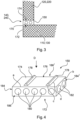
- Fig. 2 shows a building section 200 with a floor slab 110, a building wall 220 and a ceiling slab 130.
- the Fig. 2 The building wall 220 shown is connected to the underlying floor slab 110 by means of an arrangement 240.
- the arrangement 240 for connecting the vertical building wall 220 to the base plate 110 has at least one molded block 150 designed as a fixed bearing block and several molded blocks 160 designed as sliding bearing blocks.
- the molded block 150 designed as a fixed bearing block is arranged approximately in the middle area, i.e. the shear center (SM), in relation to the longitudinal direction of the building wall 220.
- SM shear center
- a single fixed bearing area 155 is formed in the middle area of the wall, and sliding bearing areas 165 made of molded blocks 160 designed as sliding bearing blocks are arranged on both sides of the fixed bearing area 155.
- the Fig. 2 The building wall 220 shown is thus fixed in the central region, preferably around the shear center of the building wall 220, to the underlying floor slab 110 and/or the ceiling slab 130, which, however, is not shown in more detail in the present embodiment.
- the building wall 220 above the sliding bearing areas can move on both sides of the fixed bearing area relative to the floor plate 110 and the ceiling plate 130.
- the Fig.3 shows a sectional view of an arrangement 140 arranged between the floor slab 110 and the building wall 120 in the area of a fixed bearing block 150.
- the molded block 150 has a molded body 170 made of concrete material, which has a support surface 172 facing the floor or underlying ceiling slab and a support surface 174 running essentially parallel thereto and facing the building wall 120 to be supported.
- Fig.4 shows a molded block designed as a fixed bearing block and Fig.4 it can be seen that the molded body 170 has a connecting section 176 on the support surface 174 with two material projections 178 in the form of profile elements that run transversely to the direction of extension.
- the molded body 170 forms a base surface on the contact or support surface 172, 174, which is determined by the external dimensions of the molded body, in particular its side lengths a and b.
- the surface area of the base surface is the product of a*b.
- the surface area of the base surfaces of all material projections 178 at the level of the base surface is shown as being significantly smaller than 40% for illustrative purposes, in order to make it clear that the profile elements as a whole should in particular be smaller than their spaces between them.
- the base surface of a material projection 178 is determined from the dimensions shown in Fig. 3 shown edge lengths c, d.
- Such a connecting section 176 can also be on the contact surface 172, as shown Fig.4
- the connecting section 176 is designed to fix the molded block 150, for example, relative to a building wall in its longitudinal direction. In the Fig. 3
- the structure shown thus achieves a fixation of the fixed bearing module relative to the building wall 120, 220, namely in the direction of the drawing plane and thus in the longitudinal direction of the wall, in order to counteract a relative movement between the building parts.
- the molded component 150 has a plurality of insulating body sections 180, 182, which run essentially parallel to and between the contact surface 172 and the support surface 174.
- the molded body has a cuboid shape.
- the insulating body sections 180, 182 extend from a first side surface 184 to the oppositely arranged first side surface 184' or from a second side surface 186 to an oppositely arranged second side surface 186 ⁇ through the molded block 150.
- the insulating body sections 180, 182 run essentially transversely to one another and form a grid or cross structure within the molded body 170 in order to form an insulation matrix in particular.
- the insulating body sections shown have a circular cross-section. In an alternative embodiment, the cross-section is elliptical or at least oval.
- Fig.5 shows a molded component 160 designed as a sliding bearing component, which comprises a molded body 170 with a contact surface 172 and a support surface 174.
- the molded body 170 of the molded component 160 designed as a sliding bearing component has a sliding section 188 on the support surface 174 and/or on the contact surface 172.
- the sliding section 188 is in the embodiment shown of the Fig.5 a very smooth surface that allows sliding and thus relative movement between the sliding bearing module and the floor or ceiling slab underneath and the building wall above.
- the molded block 160 designed as a sliding bearing block also has a plurality of insulating body sections 180, 182 which extend from a side surface 184, 184' to the oppositely arranged side surface 186, 186' of the molded block 160.
- the sliding section 188 is designed as a guide section, wherein in an alternative embodiment the molded block 160 designed as a sliding bearing block has a profile element on the support surface 174 and/or the contact surface 172 which extends in the longitudinal direction of the building wall accommodated by the molded block.
- the profile element can be a rail body, for example.
- Fig.6 shows an insulation matrix 190, which is formed from several insulation body sections 192, 194.
- the insulation matrix 190 has at least four insulating body sections 192, which run parallel to one another in a first direction, and at least three insulating body sections 194, which run parallel to one another and preferably approximately transversely to the insulating body sections 192.
- the insulating body sections 192, 194 of the insulation matrix have an oval or elliptical cross-section in the embodiment shown, which in the Figure 6 but is only indicated.
- the insulating body sections 192, 194 of the insulation matrix run in one plane.
- the insulation matrix shown forms, in particular in one embodiment of a method for producing a molded block 150, 160 for placement on a floor or ceiling plate, a
- the insulation matrix 190 is inserted or placed in at least a partially closed formwork or mold and then the formwork or the mold is filled with a concrete material forming the mold body of the molded block 150, 160.
- the insulation matrix 190 itself is manufactured beforehand in a separate process step or is manufactured independently of the process for producing a molded block and is only provided as a finished component.
Landscapes
- Engineering & Computer Science (AREA)
- Architecture (AREA)
- Civil Engineering (AREA)
- Structural Engineering (AREA)
- Physics & Mathematics (AREA)
- Acoustics & Sound (AREA)
- Electromagnetism (AREA)
- Building Environments (AREA)
Priority Applications (3)
| Application Number | Priority Date | Filing Date | Title |
|---|---|---|---|
| HUE16189204A HUE066967T2 (hu) | 2016-09-16 | 2016-09-16 | Elrendezés egy épületfal összekötésére egy öntött padló- vagy mennyezetlemezzel és alakos építõelem egy ilyen elrendezéshez |
| PL16189204.7T PL3296476T3 (pl) | 2016-09-16 | 2016-09-16 | Układ do łączenia ściany budynku z płytą podłogową lub stropową i kształtowy blok budowlany dla takiego układu |
| EP16189204.7A EP3296476B1 (de) | 2016-09-16 | 2016-09-16 | Anordnung zum verbinden einer gebäudewand mit einer boden- oder deckenplatte und formbaustein für eine solche anordnung |
Applications Claiming Priority (1)
| Application Number | Priority Date | Filing Date | Title |
|---|---|---|---|
| EP16189204.7A EP3296476B1 (de) | 2016-09-16 | 2016-09-16 | Anordnung zum verbinden einer gebäudewand mit einer boden- oder deckenplatte und formbaustein für eine solche anordnung |
Publications (3)
| Publication Number | Publication Date |
|---|---|
| EP3296476A1 EP3296476A1 (de) | 2018-03-21 |
| EP3296476B1 true EP3296476B1 (de) | 2024-04-24 |
| EP3296476C0 EP3296476C0 (de) | 2024-04-24 |
Family
ID=56958774
Family Applications (1)
| Application Number | Title | Priority Date | Filing Date |
|---|---|---|---|
| EP16189204.7A Active EP3296476B1 (de) | 2016-09-16 | 2016-09-16 | Anordnung zum verbinden einer gebäudewand mit einer boden- oder deckenplatte und formbaustein für eine solche anordnung |
Country Status (3)
| Country | Link |
|---|---|
| EP (1) | EP3296476B1 (pl) |
| HU (1) | HUE066967T2 (pl) |
| PL (1) | PL3296476T3 (pl) |
Families Citing this family (3)
| Publication number | Priority date | Publication date | Assignee | Title |
|---|---|---|---|---|
| EP3467222B1 (de) * | 2017-10-09 | 2025-04-02 | Schöck Bauteile GmbH | Formbaustein zum anordnen zwischen einer gebäudewand und einer boden- oder deckenplatte und gebäudeabschnitt mit einem solchen formbaustein |
| HUE067312T2 (hu) * | 2017-10-09 | 2024-10-28 | Schoeck Bauteile Gmbh | Alakos építõelem egy megerõsített épületfal és egy megerõsített alap- vagy födémlemez között történõ elhelyezésre és épületrész ilyen alakos építõelemmel |
| DE102023108359A1 (de) | 2023-03-31 | 2024-10-02 | Schöck Bauteile GmbH | Thermisch isolierendes Bauelement, Gebäudeabschnitt und Verfahren zum Einbau eines thermisch isolierenden Bauelementes |
Family Cites Families (4)
| Publication number | Priority date | Publication date | Assignee | Title |
|---|---|---|---|---|
| FR2201377B1 (pl) * | 1972-09-22 | 1976-03-12 | Marseille Tuileries | |
| DE29515403U1 (de) * | 1995-09-27 | 1995-12-21 | König, Siegfried, 67661 Kaiserslautern | Deckenabschalstein mit integrierter Wärmedämmung |
| DE20008570U1 (de) * | 2000-05-12 | 2001-09-27 | Schöck Bauteile GmbH, 76534 Baden-Baden | Mauersteinförmiges Wärmedämmelement |
| ES2478045T3 (es) | 2010-11-19 | 2014-07-18 | Georg Koch | Elemento de conexión que transmite una fuerza de compresión y aislante |
-
2016
- 2016-09-16 EP EP16189204.7A patent/EP3296476B1/de active Active
- 2016-09-16 PL PL16189204.7T patent/PL3296476T3/pl unknown
- 2016-09-16 HU HUE16189204A patent/HUE066967T2/hu unknown
Also Published As
| Publication number | Publication date |
|---|---|
| EP3296476C0 (de) | 2024-04-24 |
| HUE066967T2 (hu) | 2024-09-28 |
| PL3296476T3 (pl) | 2024-09-02 |
| EP3296476A1 (de) | 2018-03-21 |
Similar Documents
| Publication | Publication Date | Title |
|---|---|---|
| EP2455557B1 (de) | Druckkraft übertragendes Anschlusselement | |
| DE60023159T2 (de) | Hohlplatte zur herstellung von einem bodenfeld in welches leitungen eingebaut werden können und verfahren zum herstellen eines bodenfelds mit leitungen | |
| AT523599B1 (de) | Verfahren zur Herstellung eines Verbundelementes sowie Verbundelement | |
| EP3296476B1 (de) | Anordnung zum verbinden einer gebäudewand mit einer boden- oder deckenplatte und formbaustein für eine solche anordnung | |
| EP3385462B1 (de) | Thermisch isolierendes bauelement | |
| DE4203815A1 (de) | Betonfertigplatte fuer einen verbundboden | |
| EP0121685A2 (de) | Druckelement in einem wärmedämmenden Bauteil für vorkragende Gebäudeteile | |
| EP3296478B1 (de) | Anordnung zum verbinden einer gebäudewand mit einer boden- oder deckenplatte und formbaustein für eine solche anordnung | |
| CH677249A5 (en) | Bridging grid for structural beams - is of rod construction, with short, bent spacer welded between upper and lower horizontals | |
| EP3225758A1 (de) | Anschlussbauteil zur wärmeentkopplung zwischen einem vertikalen und einem horizontalen gebäudeteil | |
| EP3467222B1 (de) | Formbaustein zum anordnen zwischen einer gebäudewand und einer boden- oder deckenplatte und gebäudeabschnitt mit einem solchen formbaustein | |
| EP3492665A1 (de) | Betonfertigteil mit mindestens einem eine last aufnehmenden bauteil sowie anschlussplatte zur anordnung in der anschlussfuge zwischen einem solchen betonfertigteil und lastaufnehmendem bauteil | |
| DE202007007286U1 (de) | Gerippte vorgefertigte Platte | |
| EP3067484A1 (de) | Holzplatte für eine holz-beton-verbundkonstruktion, holz-beton-verbundkonstruktion und verfahren zu deren herstellung | |
| EP3296477B1 (de) | Formbaustein zum anordnen auf einer boden- oder auf oder unter einer deckenplatte und verfahren zum herstellen des formbausteins | |
| EP3663474B1 (de) | Vorrichtung zur wärmeentkopplung zwischen einer betonierten gebäudewand und einer geschossdecke sowie herstellverfahren | |
| DE10259961B4 (de) | Vorgefertigtes Bauelement, insbesondere Decken- oder Wandbauelement aus einem ausgehärteten Material | |
| EP0933482A2 (de) | Fertigbauteil für eine auskragende Balkonplatte | |
| EP4400668A2 (de) | Formbaustein zum anordnen zwischen einer gebäudewand und einer boden- oder deckenplatte und gebäudeabschnitt mit einem solchen formbaustein | |
| EP2080845A1 (de) | Holzfertigbauelement | |
| EP3467220B1 (de) | Gebäudeabschnitt und verfahren zum herstellen eines solchen gebäudeabschnitts | |
| EP3912778B1 (de) | Verfahren zur liegenden herstellung eines tragenden, vertikalen betonfertigteils und tragendes, vertikales betonfertigteil | |
| EP3663475B1 (de) | Vorrichtung zur wärmeentkopplung zwischen einer betonierten gebäudewand und einer geschossdecke sowie herstellverfahren | |
| EP1528173A2 (de) | Vorgespannte Flachdecke mit Hohldeckenplatten | |
| CH720665A2 (de) | Verstärkungselement für ein Durchstanz- und Schubbewehrungssystem für ein Betonbauelement |
Legal Events
| Date | Code | Title | Description |
|---|---|---|---|
| PUAI | Public reference made under article 153(3) epc to a published international application that has entered the european phase |
Free format text: ORIGINAL CODE: 0009012 |
|
| STAA | Information on the status of an ep patent application or granted ep patent |
Free format text: STATUS: THE APPLICATION HAS BEEN PUBLISHED |
|
| AK | Designated contracting states |
Kind code of ref document: A1 Designated state(s): AL AT BE BG CH CY CZ DE DK EE ES FI FR GB GR HR HU IE IS IT LI LT LU LV MC MK MT NL NO PL PT RO RS SE SI SK SM TR |
|
| AX | Request for extension of the european patent |
Extension state: BA ME |
|
| STAA | Information on the status of an ep patent application or granted ep patent |
Free format text: STATUS: REQUEST FOR EXAMINATION WAS MADE |
|
| 17P | Request for examination filed |
Effective date: 20180921 |
|
| RBV | Designated contracting states (corrected) |
Designated state(s): AL AT BE BG CH CY CZ DE DK EE ES FI FR GB GR HR HU IE IS IT LI LT LU LV MC MK MT NL NO PL PT RO RS SE SI SK SM TR |
|
| RAP1 | Party data changed (applicant data changed or rights of an application transferred) |
Owner name: SCHOECK BAUTEILE GMBH |
|
| STAA | Information on the status of an ep patent application or granted ep patent |
Free format text: STATUS: EXAMINATION IS IN PROGRESS |
|
| 17Q | First examination report despatched |
Effective date: 20210810 |
|
| RAP3 | Party data changed (applicant data changed or rights of an application transferred) |
Owner name: SCHOECK BAUTEILE GMBH |
|
| GRAP | Despatch of communication of intention to grant a patent |
Free format text: ORIGINAL CODE: EPIDOSNIGR1 |
|
| STAA | Information on the status of an ep patent application or granted ep patent |
Free format text: STATUS: GRANT OF PATENT IS INTENDED |
|
| RIC1 | Information provided on ipc code assigned before grant |
Ipc: E04B 2/02 20060101ALN20231108BHEP Ipc: E04B 1/76 20060101ALN20231108BHEP Ipc: E04C 1/41 20060101ALI20231108BHEP Ipc: E04B 1/78 20060101ALI20231108BHEP Ipc: E04B 1/16 20060101AFI20231108BHEP |
|
| INTG | Intention to grant announced |
Effective date: 20231124 |
|
| GRAS | Grant fee paid |
Free format text: ORIGINAL CODE: EPIDOSNIGR3 |
|
| GRAA | (expected) grant |
Free format text: ORIGINAL CODE: 0009210 |
|
| STAA | Information on the status of an ep patent application or granted ep patent |
Free format text: STATUS: THE PATENT HAS BEEN GRANTED |
|
| AK | Designated contracting states |
Kind code of ref document: B1 Designated state(s): AL AT BE BG CH CY CZ DE DK EE ES FI FR GB GR HR HU IE IS IT LI LT LU LV MC MK MT NL NO PL PT RO RS SE SI SK SM TR |
|
| REG | Reference to a national code |
Ref country code: GB Ref legal event code: FG4D Free format text: NOT ENGLISH |
|
| REG | Reference to a national code |
Ref country code: CH Ref legal event code: EP |
|
| REG | Reference to a national code |
Ref country code: DE Ref legal event code: R096 Ref document number: 502016016481 Country of ref document: DE |
|
| REG | Reference to a national code |
Ref country code: IE Ref legal event code: FG4D Free format text: LANGUAGE OF EP DOCUMENT: GERMAN |
|
| U01 | Request for unitary effect filed |
Effective date: 20240424 |
|
| U07 | Unitary effect registered |
Designated state(s): AT BE BG DE DK EE FI FR IT LT LU LV MT NL PT SE SI Effective date: 20240502 |
|
| U20 | Renewal fee for the european patent with unitary effect paid |
Year of fee payment: 9 Effective date: 20240814 |
|
| REG | Reference to a national code |
Ref country code: HU Ref legal event code: AG4A Ref document number: E066967 Country of ref document: HU |
|
| PG25 | Lapsed in a contracting state [announced via postgrant information from national office to epo] |
Ref country code: IS Free format text: LAPSE BECAUSE OF FAILURE TO SUBMIT A TRANSLATION OF THE DESCRIPTION OR TO PAY THE FEE WITHIN THE PRESCRIBED TIME-LIMIT Effective date: 20240824 |
|
| PG25 | Lapsed in a contracting state [announced via postgrant information from national office to epo] |
Ref country code: HR Free format text: LAPSE BECAUSE OF FAILURE TO SUBMIT A TRANSLATION OF THE DESCRIPTION OR TO PAY THE FEE WITHIN THE PRESCRIBED TIME-LIMIT Effective date: 20240424 |
|
| PG25 | Lapsed in a contracting state [announced via postgrant information from national office to epo] |
Ref country code: GR Free format text: LAPSE BECAUSE OF FAILURE TO SUBMIT A TRANSLATION OF THE DESCRIPTION OR TO PAY THE FEE WITHIN THE PRESCRIBED TIME-LIMIT Effective date: 20240725 |
|
| PG25 | Lapsed in a contracting state [announced via postgrant information from national office to epo] |
Ref country code: ES Free format text: LAPSE BECAUSE OF FAILURE TO SUBMIT A TRANSLATION OF THE DESCRIPTION OR TO PAY THE FEE WITHIN THE PRESCRIBED TIME-LIMIT Effective date: 20240424 |
|
| PG25 | Lapsed in a contracting state [announced via postgrant information from national office to epo] |
Ref country code: NO Free format text: LAPSE BECAUSE OF FAILURE TO SUBMIT A TRANSLATION OF THE DESCRIPTION OR TO PAY THE FEE WITHIN THE PRESCRIBED TIME-LIMIT Effective date: 20240724 Ref country code: IS Free format text: LAPSE BECAUSE OF FAILURE TO SUBMIT A TRANSLATION OF THE DESCRIPTION OR TO PAY THE FEE WITHIN THE PRESCRIBED TIME-LIMIT Effective date: 20240824 Ref country code: HR Free format text: LAPSE BECAUSE OF FAILURE TO SUBMIT A TRANSLATION OF THE DESCRIPTION OR TO PAY THE FEE WITHIN THE PRESCRIBED TIME-LIMIT Effective date: 20240424 Ref country code: GR Free format text: LAPSE BECAUSE OF FAILURE TO SUBMIT A TRANSLATION OF THE DESCRIPTION OR TO PAY THE FEE WITHIN THE PRESCRIBED TIME-LIMIT Effective date: 20240725 Ref country code: ES Free format text: LAPSE BECAUSE OF FAILURE TO SUBMIT A TRANSLATION OF THE DESCRIPTION OR TO PAY THE FEE WITHIN THE PRESCRIBED TIME-LIMIT Effective date: 20240424 Ref country code: RS Free format text: LAPSE BECAUSE OF FAILURE TO SUBMIT A TRANSLATION OF THE DESCRIPTION OR TO PAY THE FEE WITHIN THE PRESCRIBED TIME-LIMIT Effective date: 20240724 |
|
| PG25 | Lapsed in a contracting state [announced via postgrant information from national office to epo] |
Ref country code: SK Free format text: LAPSE BECAUSE OF FAILURE TO SUBMIT A TRANSLATION OF THE DESCRIPTION OR TO PAY THE FEE WITHIN THE PRESCRIBED TIME-LIMIT Effective date: 20240424 Ref country code: RO Free format text: LAPSE BECAUSE OF FAILURE TO SUBMIT A TRANSLATION OF THE DESCRIPTION OR TO PAY THE FEE WITHIN THE PRESCRIBED TIME-LIMIT Effective date: 20240424 |
|
| REG | Reference to a national code |
Ref country code: DE Ref legal event code: R097 Ref document number: 502016016481 Country of ref document: DE |
|
| PG25 | Lapsed in a contracting state [announced via postgrant information from national office to epo] |
Ref country code: SM Free format text: LAPSE BECAUSE OF FAILURE TO SUBMIT A TRANSLATION OF THE DESCRIPTION OR TO PAY THE FEE WITHIN THE PRESCRIBED TIME-LIMIT Effective date: 20240424 |
|
| PG25 | Lapsed in a contracting state [announced via postgrant information from national office to epo] |
Ref country code: SM Free format text: LAPSE BECAUSE OF FAILURE TO SUBMIT A TRANSLATION OF THE DESCRIPTION OR TO PAY THE FEE WITHIN THE PRESCRIBED TIME-LIMIT Effective date: 20240424 Ref country code: SK Free format text: LAPSE BECAUSE OF FAILURE TO SUBMIT A TRANSLATION OF THE DESCRIPTION OR TO PAY THE FEE WITHIN THE PRESCRIBED TIME-LIMIT Effective date: 20240424 Ref country code: RO Free format text: LAPSE BECAUSE OF FAILURE TO SUBMIT A TRANSLATION OF THE DESCRIPTION OR TO PAY THE FEE WITHIN THE PRESCRIBED TIME-LIMIT Effective date: 20240424 |
|
| PGFP | Annual fee paid to national office [announced via postgrant information from national office to epo] |
Ref country code: CH Payment date: 20241001 Year of fee payment: 9 |
|
| PLBE | No opposition filed within time limit |
Free format text: ORIGINAL CODE: 0009261 |
|
| STAA | Information on the status of an ep patent application or granted ep patent |
Free format text: STATUS: NO OPPOSITION FILED WITHIN TIME LIMIT |
|
| 26N | No opposition filed |
Effective date: 20250127 |
|
| PG25 | Lapsed in a contracting state [announced via postgrant information from national office to epo] |
Ref country code: MC Free format text: LAPSE BECAUSE OF FAILURE TO SUBMIT A TRANSLATION OF THE DESCRIPTION OR TO PAY THE FEE WITHIN THE PRESCRIBED TIME-LIMIT Effective date: 20240424 |
|
| PG25 | Lapsed in a contracting state [announced via postgrant information from national office to epo] |
Ref country code: IE Free format text: LAPSE BECAUSE OF NON-PAYMENT OF DUE FEES Effective date: 20240916 |
|
| REG | Reference to a national code |
Ref country code: CH Ref legal event code: U11 Free format text: ST27 STATUS EVENT CODE: U-0-0-U10-U11 (AS PROVIDED BY THE NATIONAL OFFICE) Effective date: 20251001 |
|
| U20 | Renewal fee for the european patent with unitary effect paid |
Year of fee payment: 10 Effective date: 20250827 |
|
| PGFP | Annual fee paid to national office [announced via postgrant information from national office to epo] |
Ref country code: PL Payment date: 20250827 Year of fee payment: 10 |
|
| PGFP | Annual fee paid to national office [announced via postgrant information from national office to epo] |
Ref country code: HU Payment date: 20250911 Year of fee payment: 10 Ref country code: GB Payment date: 20250923 Year of fee payment: 10 |
|
| PGFP | Annual fee paid to national office [announced via postgrant information from national office to epo] |
Ref country code: CZ Payment date: 20250903 Year of fee payment: 10 |