EP3296232A1 - Zusammenklappbarer behälter und vorrichtung zum öffnen und schliessen desselben - Google Patents
Zusammenklappbarer behälter und vorrichtung zum öffnen und schliessen desselben Download PDFInfo
- Publication number
- EP3296232A1 EP3296232A1 EP16807835.0A EP16807835A EP3296232A1 EP 3296232 A1 EP3296232 A1 EP 3296232A1 EP 16807835 A EP16807835 A EP 16807835A EP 3296232 A1 EP3296232 A1 EP 3296232A1
- Authority
- EP
- European Patent Office
- Prior art keywords
- panel
- foldable container
- lateral
- unit
- folding
- Prior art date
- Legal status (The legal status is an assumption and is not a legal conclusion. Google has not performed a legal analysis and makes no representation as to the accuracy of the status listed.)
- Granted
Links
Images


Classifications
-
- B—PERFORMING OPERATIONS; TRANSPORTING
- B62—LAND VEHICLES FOR TRAVELLING OTHERWISE THAN ON RAILS
- B62B—HAND-PROPELLED VEHICLES, e.g. HAND CARTS OR PERAMBULATORS; SLEDGES
- B62B3/00—Hand carts having more than one axis carrying transport wheels; Steering devices therefor; Equipment therefor
- B62B3/02—Hand carts having more than one axis carrying transport wheels; Steering devices therefor; Equipment therefor involving parts being adjustable, collapsible, attachable, detachable or convertible
-
- B—PERFORMING OPERATIONS; TRANSPORTING
- B65—CONVEYING; PACKING; STORING; HANDLING THIN OR FILAMENTARY MATERIAL
- B65D—CONTAINERS FOR STORAGE OR TRANSPORT OF ARTICLES OR MATERIALS, e.g. BAGS, BARRELS, BOTTLES, BOXES, CANS, CARTONS, CRATES, DRUMS, JARS, TANKS, HOPPERS, FORWARDING CONTAINERS; ACCESSORIES, CLOSURES, OR FITTINGS THEREFOR; PACKAGING ELEMENTS; PACKAGES
- B65D88/00—Large containers
- B65D88/52—Large containers collapsible, i.e. with walls hinged together or detachably connected
- B65D88/522—Large containers collapsible, i.e. with walls hinged together or detachably connected all side walls hingedly connected to each other or to another component of the container
- B65D88/524—Large containers collapsible, i.e. with walls hinged together or detachably connected all side walls hingedly connected to each other or to another component of the container and one or more side walls being foldable along an additional median line
-
- B—PERFORMING OPERATIONS; TRANSPORTING
- B65—CONVEYING; PACKING; STORING; HANDLING THIN OR FILAMENTARY MATERIAL
- B65D—CONTAINERS FOR STORAGE OR TRANSPORT OF ARTICLES OR MATERIALS, e.g. BAGS, BARRELS, BOTTLES, BOXES, CANS, CARTONS, CRATES, DRUMS, JARS, TANKS, HOPPERS, FORWARDING CONTAINERS; ACCESSORIES, CLOSURES, OR FITTINGS THEREFOR; PACKAGING ELEMENTS; PACKAGES
- B65D88/00—Large containers
- B65D88/02—Large containers rigid
- B65D88/12—Large containers rigid specially adapted for transport
- B65D88/121—ISO containers
-
- B—PERFORMING OPERATIONS; TRANSPORTING
- B65—CONVEYING; PACKING; STORING; HANDLING THIN OR FILAMENTARY MATERIAL
- B65D—CONTAINERS FOR STORAGE OR TRANSPORT OF ARTICLES OR MATERIALS, e.g. BAGS, BARRELS, BOTTLES, BOXES, CANS, CARTONS, CRATES, DRUMS, JARS, TANKS, HOPPERS, FORWARDING CONTAINERS; ACCESSORIES, CLOSURES, OR FITTINGS THEREFOR; PACKAGING ELEMENTS; PACKAGES
- B65D88/00—Large containers
- B65D88/52—Large containers collapsible, i.e. with walls hinged together or detachably connected
- B65D88/522—Large containers collapsible, i.e. with walls hinged together or detachably connected all side walls hingedly connected to each other or to another component of the container
-
- B—PERFORMING OPERATIONS; TRANSPORTING
- B66—HOISTING; LIFTING; HAULING
- B66D—CAPSTANS; WINCHES; TACKLES, e.g. PULLEY BLOCKS; HOISTS
- B66D3/00—Portable or mobile lifting or hauling appliances
- B66D3/18—Power-operated hoists
Definitions
- the present disclosure relates to a foldable container and an apparatus for folding and unfolding the same.
- a container in general, includes four corner beams as supports and panels each having a predetermined area as six surfaces, i.e., front, rear, left, right, top, and bottom surfaces, between the supports and interlocked and assembled by welding or using a fastening means such as rivet to form a space therein for transport or storage of freight.
- a conventional container has a fixed space regardless of whether freight is loaded or not, and, thus, even when an empty container without freight is transported, the empty container needs to be transported as mounted on a freight truck in spite of being light in weight like a container loaded with freight. Therefore, a single freight truck cannot transport multiple empty containers stacked thereon.
- containers when transported on a ship in a harbor, containers are stacked in multiple stages. Like containers loaded with freight, empty containers are also transported as stacked and thus occupy a lot of space of the ship, which results in an increase in cost of transport.
- the containers are stacked in multiple stages. Since the containers are stacked in their original form, they require a wide storage place.
- general containers for shipping freight are high-weight and large-sized structure unlike lightweight plastic containers and thus can be damaged or deformed by load and collision when stacked.
- Korean Patent Laid-open Publication No. 10-1999-0064773 discloses a foldable container house in which a front plate and a rear plate provided as a pair of foldable unit members between top and bottom plates formed as single boards to cover a front side and a rear side, respectively, and upper portions of lateral plates are formed as free ends and lower portions thereof are connected to the bottom plate with pivot pins, and, thus, the front and rear plates and the lateral plates are foldable to each other.
- the present disclosure is conceived to solve the above-described problem of the conventional technology and provides a foldable container which makes it possible to fold and stack empty containers without freight and then store and transport them and thus minimize a space required for storage and transport and also reduce costs related thereto.
- the present disclosure provides a foldable container which makes it possible to endure a load of stacked containers when multiple unfolded or folded containers are stacked.
- the present disclosure provides an apparatus for folding and unfolding a foldable container which makes it possible to reduce the costs of folding and unfolding a foldable container and increase the safety and efficiency in folding and unfolding.
- a lateral panel of a foldable container includes: an upper lateral panel hinge-connected to an upper panel; a lower lateral panel positioned under the upper lateral panel and hinge-connected to a lower panel; and one or more sliding joints connecting the upper lateral panel and the lower lateral panel, and as the upper panel is moved upwards, the upper lateral panel is moved upwards a predetermined distance and then the lateral panel is folded.
- a foldable container includes: a lower panel; an upper panel provided in parallel with the lower panel; first and second lateral panels of which upper and lower ends are respectively connected to the upper panel and the lower panel to be rotatable along a longitudinal direction of the upper panel and the lower panel and which are configured to be folded toward the inside of the foldable container; and front and rear panels connected to the lower panel to be rotatable along a transverse direction of the lower panel, and the first and second lateral panels include: upper lateral panels hinge-connected to the upper panel; lower lateral panels positioned under the upper lateral panels, respectively, and hinge-connected to the lower panel; and one or more sliding joints connecting the upper lateral panel and the lower lateral panel, and as the upper panel is moved upwards, the upper lateral panels are moved upwards a predetermined distance and then the first and second lateral panel are folded.
- An apparatus for folding and unfolding a foldable container includes: a main body; an upper fixing unit provided on an upper part of the main body and configured to fix an upper part of the foldable container; a front/rear side folding/unfolding unit provided on the upper part of the main body and configured to fold and unfold a front panel or a rear panel of the foldable container; and an up/down folding/unfolding unit configured to move the upper fixing unit up and down to move an upper panel and lateral panels of the foldable container up and down.
- An apparatus for folding and unfolding a foldable container includes: a main body; an upper fixing unit provided on an upper part of the main body and configured to fix an upper part of the foldable container; a front/rear side folding/unfolding unit provided on the upper part of the main body and configured to fold and unfold a front panel or a rear panel of the foldable container; and an up/down folding/unfolding unit provided on the upper part of the main body and configured to move the upper fixing unit up and down to move an upper panel and lateral panels of the foldable container up and down.
- empty containers without freight among containers used for freight transport can be folded and then stacked, and, thus, the efficiency in storage and transport can be greatly increased.
- folded containers can be stacked and then stored and transported in batches, and, thus, the efficiency in maintenance of containers and a life of the containers can be increased.
- an upper side sill and an upper reinforcing piece combined with a longitudinal frame of an upper panel and a lower side sill and a lower reinforcing piece combined with a longitudinal frame of a lower panel are provided, and, thus, it is possible to endure a vertical load of stacked containers, a freight load applied when freight is loaded, and lifting of an upper part of a container.
- a separate apparatus for folding and unfolding a foldable container is used, and, thus, the foldable container can be folded and unfolded safely and conveniently. Further, a reach stacker and a forklift which are high-priced equipment of handling containers do not need to be used. Thus, the present disclosure has more economic effects.
- the folding/unfolding apparatus can easily move the folding/unfolding apparatus, and when a foldable container is folded and unfolded, the low-priced folding/unfolding apparatus is used instead of high-priced container handling equipment. Thus, the costs of folding and unfolding the foldable container can be reduced.
- various safety devices and dedicated devices are provided to be suitable for the order and characteristics of folding and unfolding a foldable container.
- the foldable container can be rapidly folded and unfolded in a stable and efficient manner.
- connection to or “coupled to” that is used to designate a connection or coupling of one element to another element includes both a case that an element is “directly connected or coupled to” another element and a case that an element is “electronically connected or coupled to” another element via still another element.
- the term "on” that is used to designate a position of one element with respect to another element includes both a case that the one element is adjacent to the another element and a case that any other element exists between these two elements.
- the term “comprises or includes” and/or “comprising or including” used in the document means that one or more other components, steps, operation and/or existence or addition of elements are not excluded in addition to the described components, steps, operation and/or elements unless context dictates otherwise.
- the term “about or approximately” or “substantially” is intended to have meanings close to numerical values or ranges specified with an allowable error and intended to prevent accurate or absolute numerical values disclosed for understanding of the present disclosure from being illegally or unfairly used by any unconscionable third party.
- the term “step of” does not mean “step for”.
- the present disclosure relates to a foldable container and an apparatus for folding and unfolding the same.
- FIG. 1 is a perspective view of a foldable container in accordance with an exemplary embodiment of the present disclosure
- FIG. 2 is a side view of the foldable container in accordance with an exemplary embodiment of the present disclosure
- FIG. 3 and FIG. 4 are enlarged views of a portion A in FIG. 1 and exemplary operation diagrams of a sliding joint in accordance with an exemplary embodiment of the present disclosure
- FIG. 5 provides a partially enlarged view and a partial cross-sectional view of a lower panel in accordance with an exemplary embodiment of the present disclosure
- FIG. 6 provides exemplary operation diagrams of a cover portion in accordance with an exemplary embodiment of the present disclosure
- FIG. 1 is a perspective view of a foldable container in accordance with an exemplary embodiment of the present disclosure
- FIG. 2 is a side view of the foldable container in accordance with an exemplary embodiment of the present disclosure
- FIG. 3 and FIG. 4 are enlarged views of a portion A in FIG. 1 and exemplary operation diagrams of a sliding joint in accord
- FIG. 7 provides diagrams illustrating a hinge portion of a front panel in accordance with an exemplary embodiment of the present disclosure
- FIG. 8 provides a partial perspective view and a partially see-through view of a lower edge of the foldable container in accordance with an exemplary embodiment of the present disclosure
- FIG. 9 is a diagram provided to illustrate an operating of folding a front panel illustrated in FIG. 8
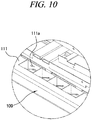
- FIG. 10 is a diagram provided to explain a locking device storage unit in accordance with an exemplary embodiment of the present disclosure
- FIG. 11 is a diagram provided to explain a configuration for fixing a front panel and a rear panel to an upper panel in accordance with an exemplary embodiment of the present disclosure
- FIG. 12 is a diagram provided to explain a configuration for fixing a front panel and a rear panel to an upper panel in accordance with another exemplary embodiment of the present disclosure
- FIG. 13 is a side view of a configuration fixed by the front panel and the rear panel illustrated in FIG. 11 and FIG. 12
- FIG. 14 is a diagram provided to explain a member for fixing a lateral panel in accordance with an exemplary embodiment of the present disclosure
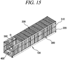
- FIG. 15 is a partial cross-sectional perspective view of the foldable container in accordance with an exemplary embodiment of the present disclosure
- FIG. 16 is an enlarged view of a portion D in FIG. 15
- FIG. 17 provides exemplary operation diagrams of a lateral panel supporting unit in accordance with an exemplary embodiment of the present disclosure
- FIG. 18 provides enlarged views of portions B and C in FIG. 1
- FIG. 19 is a diagram provided to explain an upper reinforcing piece and a lower reinforcing piece in accordance with an exemplary embodiment of the present disclosure
- FIG. 20 is a side view of the foldable container in accordance with an exemplary embodiment of the present disclosure
- FIG. 21A is a cross-sectional view taken along a line E-E' in FIG. 20
- FIG. 21B is a cross-sectional view taken along a line F-F' in FIG. 20
- FIG. 22 provides enlarged views of portions G and H in FIG. 21A
- FIG. 23 provides enlarged views of portions I and J in FIG. 21B
- FIG. 24 is a cross-sectional perspective view taken along a line E-E' in FIG. 21
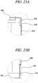
- FIG. 25A is an enlarged view of a portion K in FIG. 24
- FIG. 25B is a diagram provided to explain a fixing member of a lower lateral panel
- FIG. 26 provides cross-sectional views of the foldable container in accordance with an exemplary embodiment of the present disclosure
- FIG. 27 provides enlarged views of a portion L in FIG. 26
- FIG. 28 provides enlarged views of a portion M in FIG. 26
- FIG. 29 provides enlarged views of a portion N in FIG. 26
- FIG. 30 provides diagrams to explain a panel connection protection unit in accordance with an exemplary embodiment of the present disclosure
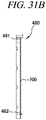
- FIG. 31 provides perspective view of a frame of a front panel in accordance with an exemplary embodiment of the present disclosure
- FIG. 32 is a diagram provided to explain a rod bar in accordance with an exemplary embodiment of the present disclosure
- FIG. 33 is a diagram provided to explain a panel connection unit in accordance with an exemplary embodiment of the present disclosure
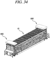
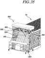
- FIG. 34 to FIG. 36 are diagrams provided to explain a method of folding the foldable container in accordance with an exemplary embodiment of the present disclosure
- FIG. 37 is a diagram illustrating a status where an apparatus for folding and unfolding a foldable container is installed on the foldable container in accordance with an exemplary embodiment of the present disclosure
- FIG. 38 is a perspective view of an apparatus for folding and unfolding a foldable container in accordance with an exemplary embodiment of the present disclosure
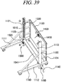
- FIG. 39 is a rear perspective view of the apparatus for folding and unfolding a foldable container in accordance with an exemplary embodiment of the present disclosure
- FIG. 40 provides enlarged views of portions O and P in FIG. 38
- FIG. 41 provides diagrams to explain an operation of a lower fixing unit in accordance with an exemplary embodiment of the present disclosure
- FIG. 42 provides diagrams to explain an operation of an upper fixing unit in accordance with an exemplary embodiment of the present disclosure
- FIG. 43 provides enlarged views of a portion Q in FIG. 39
- FIG. 44 is an enlarged view of a portion R in FIG. 39
- FIG. 45 is a diagram provided to explain an up/down folding/unfolding unit in accordance with an exemplary embodiment of the present disclosure
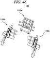
- FIG. 46 and FIG. 47 are diagrams provided to explain a main body in accordance with an exemplary embodiment of the present disclosure
- FIG. 48 to FIG. 50 are diagrams provided to explain a pulley and a lateral side fixing unit in accordance with an exemplary embodiment of the present disclosure
- FIG. 51 is a perspective view of an apparatus for folding and unfolding a foldable container in accordance with another exemplary embodiment of the present disclosure
- FIG. 52 is an enlarged view of a portion W in FIG. 51
- FIG. 53 is a side view illustrating the apparatus for folding and unfolding a foldable container to which an operation unit is added in accordance with another exemplary embodiment of the present disclosure
- FIG. 54 is a plan view illustrating the apparatus for folding and unfolding a foldable container to which the operation unit is added in accordance with another exemplary embodiment of the present disclosure
- FIG. 55 to FIG. 58 are diagrams provided to explain a method of folding and unfolding a foldable container using the apparatus for folding and unfolding a foldable container in accordance with an exemplary embodiment of the present disclosure
- FIG. 59 is a diagram illustrating a status where multiple folded foldable containers are stacked in accordance with an exemplary embodiment of the present disclosure.
- present foldable container 10 a foldable container 10 according to an exemplary embodiment of the present disclosure (hereinafter, referred to as "present foldable container 10") will be described.
- the present foldable container 10 includes a lower panel 100, an upper panel 200 provided in parallel with the lower panel 100, first and second lateral panels 301 and 302 of which upper and lower ends are respectively connected to the upper panel 200 and the lower panel 100 to be rotatable along a longitudinal direction of the upper panel 200 and the lower panel 100 and which are configured to be folded toward the inside of the foldable container 10, and a front panel 400 and a rear panel 500 connected to the lower panel 100 to be rotatable along a transverse direction of the lower panel 100.
- the longitudinal direction may refer to the 8 o'clock direction and the 2 o'clock direction in FIG. 1
- the transverse direction may refer to the 4 o'clock direction and the 10 o'clock direction in FIG. 1 .
- first lateral panel 301 and the second lateral panel 302 are positioned on lateral sides, respectively, between the upper panel 200 and the lower panel 100 and include the same components and are symmetrically provided. Therefore, the first lateral panel 301 and the second lateral panel 302 will not be separately described, but will be referred to and described as a lateral panel 300.
- the lateral panel 300 includes an upper lateral panel 310 hinge-connected to the upper panel 200, a lower lateral panel 320 positioned under the upper lateral panel 310 and hinge-connected to the lower panel 100, and one or more sliding joints 330 connecting the upper lateral panel 310 and the lower lateral panel 320.
- the upper lateral panel 310 may be hinge-connected to the upper panel 200 to be rotatable.
- at least one hinge portion 310a of the upper lateral panel 310 may be positioned at an edge of an upper inside of the upper lateral panel 310 and the hinge portion 310a of the upper lateral panel 310 may be connected to a longitudinal lower part of the upper panel 200, and the upper lateral panel 310 may be folded by being rotated toward the inside of the foldable container 10 around the hinge portion 310a of the upper lateral panel 310.
- the inside may refer to a space in the foldable container 10 where freight is loaded.
- the lower lateral panel 320 may be positioned under the upper lateral panel 310 and a lower part thereof may be hinge-connected to the lower panel 100 to be rotatable.
- at least one hinge portion 320a of the lower lateral panel 320 may be positioned at an edge of a lower inside of the lower lateral panel 320 and the hinge portion 320a of the lower lateral panel 320 may be connected to a longitudinal upper part of the lower panel 100, and the lower lateral panel 320 may be folded by being rotated toward the inside of the foldable container 10 around the hinge portion 320a of the lower lateral panel 320.
- the upper lateral panel 310 is moved upwards a predetermined distance and then the lateral panel 300 is folded.
- the upper lateral panel 310 and the lower lateral panel 320 are connected by one or more sliding joints 330.
- the sliding joint 330 includes a first fixing unit 331 connected to the upper lateral panel 310, a second fixing unit 332 connected to the lower lateral panel 320, and a link unit 333 of which one side is hinge-connected to the first fixing unit 331 and the other side is hinge-connected to the second fixing unit 332 to be slidable.
- an upper part of the first fixing unit 331 may be connected to a lower part of an outer surface of the upper lateral panel 310 and a lower part of the first fixing unit 331 may be hinge-connected to an upper part of the link unit 333.
- the second fixing unit 332 may be connected to an upper part of an outer surface of the lower lateral panel 320 and an upper part of the second fixing unit 332 may be connected to a lower part of the link unit 333.
- the upper part of the second fixing unit 332 may include a sliding dent 332a which is dented for the link unit 333 to be inserted therein, and a sliding groove 332b having a predetermined length in a vertical direction may be formed outwards in each of inner surfaces of the sliding dent 332a.
- the upper part of the link unit 333 may be hinge-connected to the lower part of the first fixing unit 331 and a sliding pine 333a may be positioned on the lower part thereof, and the sliding pin 333a may be inserted into the sliding groove 332b and then connected to the second fixing part 332 to be movable and rotatable in a vertical direction along the sliding groove 332b.
- the upper lateral panel 310 is moved upwards a predetermined distance and the link unit 333 is moved upwards the same distance along the sliding groove 332b accordingly.
- the link unit 333 is moved toward an inner lower part of the foldable container 10 at the same time when the lower part of the first fixing unit 331 and the upper part of the second fixing unit 332 are hinge-connected to the upper part and the lower part of the link unit 333, respectively, and, thus, the upper lateral panel 310 and the lower lateral panel 320 can be folded.
- the lower panel 100 in accordance with an exemplary embodiment of the present disclosure will be described with reference to FIG. 5 and FIG. 6 .
- a step portion 110 which is stepped lower than the upper surface of the lower panel 100 may be formed.
- the step portion 110 may include a step surface 111 formed in parallel with the upper surface of the lower panel 100 and a step sill surface 112 formed perpendicularly to the step surface 111 and connected to the upper surface and the step surface 111.
- the lower panel 100 may include a cover portion 140 which can cover the step portion 110 of the lower panel 100.
- hinge portions 141 of the cover portion 140 may be positioned at both ends of the cover potion 140 in a transverse direction and the hinge portions 141 of the cover portion 140 may be connected to the lateral panel 300 and rotated around an edge where the step sill surface 112 and the upper surface of the lower panel 100 meet, as illustrated in FIG. 5 and FIG. 6 .
- the cover portion 140 is not limited thereto and may be hinge-connected to an upper part of the step sill surface 112 and rotated around the edge where the step sill surface 112 and the upper surface of the lower panel 100 meet.
- the front panel 400 and the rear panel 500 are positioned on a front side and a rear side, respectively, between the upper panel 200 and the lower panel 100 and include the same components and are symmetrically provided. Therefore, an explanation of the rear panel 500 will be omitted and only the front panel 400 will be explained.
- the front panel 400 may be manufactured in the form of a door and the rear panel 500 may be manufactured in the form of a wall.
- the front panel 400 may be connected to be rotatable toward the inside of the foldable container 10.
- the front panel 400 in accordance with an exemplary embodiment of the present disclosure will be described with reference to FIG. 7 .
- the front panel 400 may be hinge-connected to the step portion 110.
- a hinge portion 420 of the front panel 400 is positioned at an inner lower edge thereof and the hinge portion 420 of the front panel 400 is positioned at the step portion 110 and the front panel 400 can be folded around the hinge portion 420 of the front panel 400 toward the inside of the foldable container 10.
- the cover portion 140 is rotated first, and then the front panel 400 can be folded inwards.
- the front panel 400 when the front panel 400 is hinge-connected to the step portion 110 and thus folded toward the inside of the foldable container 10, the front panel 400 can be folded without interference in a bottom surface of the lower panel 100 and a step with respect to the upper surface of the lower panel 100 can be eliminated and the introduction of external foreign materials into the foldable container 10 can be suppressed while a door in the front panel 400 is maintained in size.
- the hinge portion 420 of the front panel 400 is not exposed to the outside but formed flat without unevenness on the upper surface of the lower panel 100.
- the front panel 400 and the rear panel 500 include rings 430 on their upper part, and, thus, the front panel 400 and the rear panel 500 can be rotated to be folded and unfolded by connecting a wire of the container folding/unfolding apparatus 20 to be described later to the rings 430.
- the front panel 400 and the rear panel 500 may further include a rod bar 460 connected to their upper part.
- one end of the rod bar 460 may be connected to the upper part of the front panel 400 or rear panel 500 to be rotatable and the other end thereof may be connected to the wire of the container folding/unfolding apparatus 20.
- a worker can connect the wire for rotating the front panel 400 or rear panel 500 to the other end of the rod bar 460 without entering the foldable container 10. Therefore, it is possible to suppress the risk of safety accident.
- the front panel 400 in accordance with another exemplary embodiment of the present disclosure will be described with reference to FIG. 8 and FIG. 9 .
- the front panel 400 includes a rotation protrusion 450 on a lower part of a lateral frame and a rotation recession 321 formed on an inner surface of the lateral panel 300, and, thus, the rotation protrusion 450 can be connected to the rotation recession 321 by being inserted into the rotation recession 321 to be rotatable.
- the front panel 400 includes the rotation protrusion 450 on the lower part of the lateral frame, and the rotation recession 321 into which the rotation protrusion 450 is inserted is dented to have a " " shape on the inner surface of the lateral panel 300, and if the front panel 400 is folded, the rotation protrusion 450 can be moved upwards within the rotation recession 321 and then the front panel 400 can be folded.
- the step surface 111 of the lower panel 100 may include a locking device storage unit 111a which is dented downwards and configured to store a container locking device capable of connecting edges of the foldable container 10.
- the locking device storage unit 111a is a place to store a device connecting the container 10 and the container 10 and is dented downwards on the step surface 111 and divided by partitions to store multiple container locking devices. Further, as illustrated in FIG. 10 , the locking device storage unit 111a may store four container locking devices therein to connect the respective edges of the foldable container 10, but is not limited thereto and may store multiple locking devices therein.
- a configuration in which the front panel 400 is fixed to the upper panel 200 will be described with reference to FIG. 11 to FIG. 13 .
- the front panel may include a protrusion 410 protruded on an upper surface of an upper frame of the front panel 400
- the upper panel 20 may include a recession 210 positioned on a lower surface of a transverse frame of the upper panel 200 and dented for the protrusion 410 to be inserted therein.
- the front panel 400 can be fixed without being folded toward the inside of the foldable container 10 since the protrusion 410 on the upper surface of the upper frame of the front panel 400 is inserted into the recession 210 on the lower surface of the transverse frame of the upper panel 200.
- the front panel 400 is folded toward the inside of the foldable container 10, the upper panel 200 is moved upwards a predetermined distance and the protrusion 410 gets out of the recession 210 accordingly, and, thus, the front panel 400 can be folded.
- a recession 440 may be dented on the upper surface of the upper frame of the front panel 400 and a protrusion 240 may be protruded on the lower surface of the transverse frame of the upper panel 200.
- the protrusions 240 and 410 may be formed into a cylindrical shape of which an upper edge is chamfered and thus can be easily inserted into the recessions 210 and 440.
- a folding fixing unit 340 and a lateral panel reinforcing unit 350 will be described with reference to FIG. 14 .
- the folding fixing unit 340 can function to fix the upper lateral panel 310 and the lower lateral panel 320 not to be folded toward the inside of the foldable container 10 when the foldable container 10 is used. Further, one or more folding fixing units 340 may be provided.
- the folding fixing unit 340 may be positioned on an inner side of the lateral panel, and, thus, it is possible to suppress the release of the folding fixing unit 340 from the outside and folding of the lateral panel 300.
- the folding fixing unit 340 may include a screw unit 341 protruded inwards on a lower inner surface of the upper lateral panel 310, a screw insertion unit 342 of one-side open type formed on the lateral panel reinforcing unit 350 positioned on an upper part of the lower lateral panel 320, and a bolt 343 combined with the screw unit 341.
- the one-side open type may refer to a "U" shape with an open top, so that the upper lateral panel 310 can be moved upwards even when the screw unit 341 is inserted.
- the screw unit 341 is fixed to the lower inner surface of the upper lateral panel 310, and the screw unit 341 is inserted into the screw insertion unit 342 formed on the lateral panel reinforcing unit 350 positioned on the upper part of the lower lateral panel 320 and the bolt 343 is engaged with the screw unit 341, and, thus, an upper outer surface of the lower lateral panel 320 is closely fixed to the inner surface of the upper lateral panel 310. Therefore, the upper lateral panel 310 and the lower lateral panel 320 are not folded toward the inside of the foldable container 10. Further, when the foldable container 10 is folded, the upper lateral panel 310 and the lower lateral panel 320 can be folded by removing the bolt 343.
- the lateral panel reinforcing unit 350 may be positioned along a longitudinal direction between the upper lateral panel 310 and the lower lateral panel 320.
- the lateral panel reinforcing unit 350 may support the upper lateral panel 310 hinge-connected to the upper panel 200 and enable the lateral panel 300 to be stably fixed together with the folding fixing unit 340.
- the lateral panel reinforcing unit 350 may be connected to the upper part of the lower lateral panel 320 along a longitudinal direction as a member of which a cross-section has a " ⁇ " shape, but is not limited thereto, and may be connected thereto as a member having a " ⁇ " shape, " ⁇ " shape, or "I" shape.
- a lateral panel supporting unit 360 in accordance with an exemplary embodiment of the present disclosure will be described with reference to FIG. 15 to FIG. 17 .
- a one end of the lateral panel supporting unit 360 may be hinge-connected to the upper part of the lower lateral panel 320 and when the lateral panel 300 is folded, the other end thereof may be in contact with the upper surface of the lower panel 100. Further, multiple lateral panel supporting units 360 may be provided along a longitudinal direction.
- the lateral panel supporting unit 360 may be positioned within the lateral panel reinforcing unit 350 as illustrated in FIG. 16A , but is not limited thereto and may be positioned on the upper part of the lower lateral panel 320.
- the lateral panel supporting unit 360 may be positioned not to protrude toward the inside of the lateral panel 300.
- the lateral panel supporting unit 360 may be rotated around its one side to protrude in a direction perpendicular to the inner surface of the lateral panel 300.
- the other side of the lateral panel supporting unit 360 is in contact with the upper surface of the lower panel 100 and thus can support the weight of the lateral panel 300. With this configuration, it is possible to suppress deformation of the upper panel 200 or lateral panel 300 by weight.
- An upper corner fitting 220 and a lower corner fitting 120 are provided at corners of the upper panel 200 and the lower panel 100, respectively.
- the upper corner fitting 220 and the lower corner fitting 120 are provided to endure a load applied when the foldable containers 10 are stacked in multiple stages, and when the foldable containers 10 are folded and stacked and then transported in batches, the corner fittings of the containers 10 are fixed to suppress unfolding of the foldable containers 10.
- the foldable container 10 may include the upper reinforcing piece 230 and the lower reinforcing piece 130 to fix the folded foldable container 10 not to be unfolded and endure a load applied when multiple containers are stacked on the folded foldable container 10.
- the upper reinforcing piece 230 may be extended downwards from the upper corner fitting 220 and may include a fastening piece 231.
- the lower reinforcing piece 130 may be extended upwards from the lower corner fitting 120 and may include a fastening piece fixing unit 131 to which the fastening piece 231 is inserted and fastened.
- An extension length of the upper reinforcing piece 230 and the lower reinforcing piece 130 may be appropriately selected in consideration of a thickness of the folded container.
- the upper reinforcing piece 230 and the lower reinforcing piece 130 may be extended to an appropriate length, so that when the foldable container is fully folded, the fastening piece 231 can be inserted into the fastening piece fixing unit 131 and fastening holes 231a formed in the fastening piece 231 can match up with fastening holes f formed in the fastening piece fixing unit 131, respectively.
- the upper reinforcing piece 230 is safely placed on the lower reinforcing piece 130 and the fastening piece 231 is inserted into the fastening piece fixing unit 131 at the same time, and then, the fastening piece 231 is fixed to the fastening piece fixing unit 131 by allowing fastening members to pass through the fastening holes 231a formed in the fastening piece 231 and the fastening holes 132 formed in the fastening piece fixing unit 131. Therefore, it is possible to endure a load applied when the containers 10 are stacked in multiple stages and thus possible to suppress damage to the containers 10 by weight, and also possible to suppress unfolding of the folded container 10 during transport.
- the front panel 400 can be fixed to the upper panel 200, the lower panel 100, and the lateral panel 300 by allowing the fastening members such as bolts to pass through the fastening holes 132 and 232 formed in the upper reinforcing piece 230 and the lower reinforcing piece 130 and then to be inserted into lateral upper and lower parts of the front panel 400.
- the container 10 can stably stand up.
- force applied when the foldable container 10 is lifted up by the folding/unfolding apparatus or another crane or stacked in multiple stages is not concentrated on a connection portion between the upper panel 200 and the upper lateral panel 310 and a connection portion between the lower panel 100 and the lower lateral panel 320, but can be dispersed to the front panel 400.
- An upper side sill 250 included in the upper panel 200 and a lower side sill 150 included in the lower panel 100 will be described with reference to FIG. 20 to FIG. 23 .
- An upper part of the upper side sill 250 may be connected to a longitudinal frame of the upper panel 200 and a lower part thereof may be hinge-connected to an upper part of the upper lateral panel 310.
- a lower part of the lower side sill 150 may be connected to a longitudinal frame of the lower panel 100 and an upper part thereof may be hinge-connected to a lower part of the lower lateral panel 320.
- the upper side sill 250 may include first upper side sills 251 positioned on a front side and a rear side, respectively, and a second upper side sill 252 positioned between the first upper side sills 251, and the lower side sill 150 may include first lower side sills 151 positioned on a front side and a rear side, respectively, and a second lower side sill 152 positioned between the first lower side sills 151.
- the upper side sill 250 and the lower side sill 150 may be manufactured to have one of a " ⁇ " shape, a " ⁇ ” shape, a “ ⁇ ” shape, a “ “ shape, a “ ⁇ ” shape, a “ ⁇ ” shape, an "I” shape, a "H” shape, and a “U” shape, but is not necessarily limited thereto and can be manufactured to have various shapes.
- the first upper side sills 251 positioned on a front side and a rear side, respectively, may be manufactured to have a smaller thickness than the second upper side sill 252 in order not to interfere with folding of the front panel 400 or rear panel 500.
- the first lower side sills 151 positioned on a front side and a rear side, respectively, may be manufactured to have a smaller thickness than the second lower side sill 152 in order not to interfere with folding of the front panel 400 or rear panel 500.
- the second upper side sill 252 and the second lower side sill 152 may include one or more side sill reinforcing units 153 and 253 therein and thus can improve the reinforcement.
- the second upper side sill 252 may be formed into a "U” shape and the upper side sill reinforcing unit 253 may be formed into an "I" shape therein and thus can improve the reinforcement.
- the second lower side sill 152 may be formed into a "U” shape and the lower side sill reinforcing unit 153 may be formed into an "I" shape therein and thus can improve the reinforcement.
- the upper side sill 250 and the lower side sill 150 are positioned on the upper panel 200 and the lower panel 100, respectively, it is possible to suppress deformation of the upper panel 200 caused by weight or deformation of the lower panel 100 caused by a freight load applied when freight is loaded.
- a fixing member of the lower lateral panel according to the present disclosure will be described with reference to FIG. 24 and FIG. 25 .
- the lower lateral panel 320 may be fixed to the lower side sill 150 by a fixing member 154 so as not to be rotated.
- multiple "U"-shaped grooves 322 which are open inwards are formed on a lower part of the lower lateral panel 320, a protruding screw is inserted into an upper surface of the lower side sill 150, and a bolt is combined with the screw unit, and, thus, the lower lateral panel 320 can be fixed not to be rotated.
- a panel connection protection unit 600 and an elastic member 700 in accordance with an exemplary embodiment of the present disclosure will be described with reference to FIG. 26 to FIG. 31 .
- the panel connection protection unit 600 may be positioned on each of panels provided adjacent to each other in a left-and-right or up-and-down relationship.
- the panel connection protection unit 600 may be formed by extending an outer surface of a panel toward its adjacent panel in order for a seam between the adjacent panels not to be directly exposed to the outside.
- the panel connection protection unit 600 may be formed by extending an upper panel to an outer lower direction of a lower panel, so that seams of connection portions where the upper panel 200 and the upper lateral panel 310, the upper lateral panel 310 and the lower lateral panel 320, and the lower lateral panel 320 and the lower panel 100 meet each other in an up-and-down relationship, respectively, cannot be directly exposed to the outside.
- the panel connection protection unit 600 may be formed by being extended inwards from a front surface or rear surface of the lateral panel 300, so that a seam where the lateral panel 300 and the front panel 400 or rear panel 500 meet each other in a left-and-right relationship cannot be directly exposed to the outside.
- a seam between panels is not welded, and, thus, freight can be stolen by inserting a tool through the seam.
- freight being transported is grain which is transported in bulk, a tool with a sharp end may be inserted through a seam between panels to form a small crack and the grain may be stolen through the crack.
- the panel connection protection unit 600 is positioned at a seam between panels, and, thus, the seam is not directly exposed to the outside. Therefore, it is possible to suppress stealing of freight.
- Each elastic member 700 may be positioned between panels provided adjacent to each other and may be formed of an elastic material. However, the present disclosure is not limited thereto, and the elastic member 700 may not be positioned between the panels provided adjacent to each other, and, thus, the panels may be in direct contact with each other.
- the panel connection protection unit 600 may be formed by downwardly extending a lateral surface of the upper panel 200 in a longitudinal direction.
- the present disclosure is not limited thereto, and the panel connection protection unit 600 may be connected to a lateral lower part in a longitudinal direction of the upper panel 200 as an "I"-shaped member to cover a seam between the upper panel 200 and the upper lateral panel 310 or may be connected to a lower surface in the longitudinal direction of the upper panel 200 as a " ⁇ "-shaped member.
- the panel connection protection unit 600 may be formed by downwardly extending a lateral surface of the upper lateral panel 310 in a longitudinal direction.
- the present disclosure is not limited thereto, and the panel connection protection unit 600 may be connected to a lateral lower part of the upper lateral panel 310 as an "I"-shaped member to cover a seam between the upper lateral panel 310 and the lower lateral panel 320 or may be connected to a lower surface of the upper lateral panel 310 as a " ⁇ "-shaped member.
- the elastic member 700 may be positioned between the upper lateral panel 310 and the lower lateral panel 320 to relieve shock generated during folding.
- the panel connection protection unit 600 may be formed by downwardly extending a lateral surface of the lower lateral panel 320 in a longitudinal direction.
- the present disclosure is not limited thereto, and the panel connection protection unit 600 may be connected to a lateral lower part of the lower lateral panel 320 as an "I"-shaped member to cover a seam between the lower lateral panel 320 and the lower panel 100 or may be connected to a lower surface of the lower lateral panel 320 as a " ⁇ "'-shaped member.
- the panel connection protection unit 600 may be formed by downwardly extending a lateral surface of the upper panel 200 in a transverse direction.
- the present disclosure is not limited thereto, and the panel connection protection unit 600 may be connected to a lateral lower part of a transverse frame of the upper panel 200 as an "I"-shaped member to cover a seam between the upper panel 200 and the front panel 400 or may be connected to a lower surface of the transverse frame of the upper panel 200 as a " ⁇ "-shaped member.
- the panel connection protection unit 600 may be formed by being extended inwards from a front surface or rear surface of the lateral panel 300.
- the present disclosure is not limited thereto, and the panel connection protection unit 600 may be connected to a front or rear frame of the lateral panel as an "I"-shaped member or " ⁇ "-shaped member to cover a seam between the front panel 400 and the lateral panel 300.
- connection protection unit 600 and the elastic member 700 Due to the connection protection unit 600 and the elastic member 700, an outer surface of an upper panel among panels provided adjacent to each other is downwardly extended or a separate member is connected, and, thus, it is possible to suppress the introduction of foreign materials into the foldable container 10 through a seam between the panels.
- a front frame 480 constituting the front panel 400 will be described with reference to FIG. 31 .
- An upper part of the front frame 480 may include upper fastening holes 481 formed corresponding to the fastening holes 232 formed in the upper reinforcing piece 230 and a lower part thereof may include lower fastening holes 482 formed corresponding to the fastening holes 132 formed in the fastening piece fixing unit 131 of the lower reinforcing piece 130.
- the front frame 480 may be fastened to the upper reinforcing piece 230 and the lower reinforcing piece 130 by fastening members passing through the fastening holes 232 formed in the upper reinforcing piece 230 and the upper fastening holes 481 and fastening members passing through the fastening holes 132 formed in the lower reinforcing piece 130 and the lower fastening holes 482 and thus fixed to the lower panel 100, the upper panel 200, and the lateral panel 300.
- the front frame 480 may be formed to have a thickness and a width sufficient to endure tensile force when the upper part of the foldable container 10 is lifted if the container is unfolded and a stacking load applied when multiple containers are stacked.
- the front frame 480 includes elastic members on both inner sides of the container 10 and thus can suppress the introduction of foreign materials between the front panel 400 and the lateral panel 300.
- the rear frame includes components similar to those of the front frame 480 and is symmetrically provided with the front frame 480. Therefore, an explanation of the rear frame will be omitted.
- the foldable container 10 may further include panel connection units 900 respectively positioned on both ends of the lateral panel 300 in a longitudinal direction and formed into a " ⁇ " shape into which the front frame 480 or rear frame can be inserted.
- the lateral panel 300 may be connected to the front panel 400 and the rear panel 500 and the introduction of foreign materials between the front panel 400 or rear panel 500 and the lateral panel 300 can be suppressed.
- container folding/unfolding apparatuses 800 may be positioned on a front surface and a rear surface, respectively, of the foldable container 10.
- a lower fixing unit 820 may be fixed to the lower corner fitting 120 of the lower panel 100.
- the worker may enter the foldable container 10 to release the folding fixing unit 340 and the fixing member 154 of the lower lateral panel 320, unfold the lateral panel supporting unit 360, and remove bolts or pins of the upper reinforcing piece 230 and the lower reinforcing piece 130 binding the front panel 400 and the rear panel 500.
- an folding/unfolding unit 840 including a motor may be used to move the upper panel 200 and the upper lateral panel 310 connected thereto upwards a predetermined distance using the sliding joint 330 and then fix the upper panel 200 and the upper lateral panel 310 using an upper fixing unit 830.
- the folding/unfolding unit 840 may be used to fold the front panel 400 and the rear panel 500 toward the inside of the foldable container 10.
- a dead-end of a wire 841 of the folding/unfolding unit 840 may be fixed to the rings 430 provided on the upper part of the front panel 400 or rear panel 500, and the wire 841 may be slowly unwound to slowly fold and unfold the front panel 400 and the rear panel 500.
- the upper fixing unit 830 may be released, and the folding/unfolding unit 840 may slowly move the upper panel 200 and the lateral panel 300 downwards to fold and unfold the upper panel 200 and the lateral panel 300 (see FIG. 36 ).
- the upper reinforcing piece 230 of the upper corner fitting 220 and the lower reinforcing piece 130 of the lower corner fitting 120 are connected through the fastening members to suppress unfolding of the folded foldable container 10.
- the container folding/unfolding apparatus 800 may further include a control unit to automatically control the above-described process.
- the present foldable container folding/unfolding apparatus 20 may be positioned on each of a front surface or a rear surface of the foldable container 10 as illustrated in FIG. 37 to fold and unfold the foldable container 10.
- the present foldable container folding/unfolding apparatus 20 includes a main body 1100, an upper fixing unit 1300 provided on an upper part of the main body 1100 and configured to fix the upper part of the foldable container 10, a front/rear side folding/unfolding unit 1400 provided on the upper part of the main body 1100 and configured to fold and unfold the front panel 400 and the rear panel 500 of the foldable container 10, and an up/down folding/unfolding unit 1500 configured to move the upper fixing unit 1300 up and down to move the upper panel 200 and the lateral panel 300 of the foldable container 10 up and down.
- multiple wheels 1101 are provided under the main body 1100, and, thus, the present foldable container folding/unfolding apparatus 20 can be easily moved.
- the present foldable container folding/unfolding apparatus 20 may further include a lower fixing unit 1200 provided on a lower part of the main body 1100 and configured to fix the lower part of the foldable container 10.
- the lower fixing unit 1200 and the upper fixing unit 1300 in accordance with an exemplary embodiment of the present disclosure will be described with reference to FIG. 40 to FIG. 42 .
- the lower fixing unit 1200 may include a lower fixing piece 1210 inserted into an insertion groove 120a formed in the lower corner fitting 120 of the foldable container 10 and a lower lever 1220 configured to rotate the lower fixing piece 1210.
- the lower fixing piece 1210 of the lower fixing unit 1200 may be inserted into the insertion groove 120a formed in the lower corner fitting 120 of the foldable container 10. Further, after the lower fixing piece 1210 is inserted into the insertion groove 120a in the lower corner fitting 120, the lower fixing piece 1210 is rotated by rotating the lower lever 1220, and, thus, the lower fixing unit 1200 can be fixed to the lower corner fitting 120.
- the upper fixing unit 1300 may include an upper fixing piece 1310 inserted into an insertion groove 220a formed in the upper corner fitting 220 of the foldable container 10 and an upper lever 1320 configured to rotate the upper fixing piece 1310.
- the upper fixing piece 1310 of the upper fixing unit 1300 may be inserted into the insertion groove 220a formed in the upper corner fitting 220 of the foldable container 10. Further, after the upper fixing piece 1310 is inserted into the insertion groove 220a in the upper corner fitting 220, the upper fixing piece 1310 is rotated by rotating the upper lever 1320, and, thus, the upper fixing unit 1300 can be fixed to the upper corner fitting 220.
- the upper fixing unit 1300 may be vertically movably connected to a ball screw 1510 of the up/down folding/unfolding unit 1500 to be described later.
- the wheels 1101 may be provided under the main body 1100, so that the worker can push the main body 1100 to be positioned on the front surface or rear surface of the foldable container 10.
- the main body 1100 may include a lower frame 1110, a pillar frame 1120, and an upper frame 1130.
- the lower frame 1110 may be positioned on both sides of the front surface or rear surface of the foldable container 10.
- the both sides may refer to directions in which the lateral panels 300 of the foldable container 10 are positioned.
- the lower frame 1110 may include a first lower lateral frame 1111 positioned on one side of the foldable container 10 and a second lower lateral frame 1112 positioned on the other side of the foldable container 10.
- the lower frame 1110 may be formed to be elongated toward the inside of the both sides of the foldable container 10. Therefore, it is possible to suppress falling of the present foldable container folding/unfolding apparatus 20 toward the inside when the foldable container 10 is folded and unfolded.
- the lower frame 1110 may further include a lower frame reinforcing unit 1113 of which one end is connected to one end of the first lower lateral frame 1111 and the other end is connected to one end of the second lower lateral frame 1112.
- the pillar frame 1120 may be extended upwards from an upper surface on one side of the lower frame 1110.
- the pillar frame 1120 may be formed into a one-side open " ⁇ " shape as illustrated in FIG. 38 and FIG. 39 .
- the pillar frames 1120 may include a first pillar frame 1121 extended upwards from an upper surface on one side of the first lower lateral frame 1111 and a second pillar frame 1122 extended upwards from an upper surface on one side of the second lower lateral frame 1112.
- a ladder 1124 may be positioned on one side of the pillar frame 1120.
- the worker may use the ladder 1124 to climb to an upper part of the main body 1100 and manipulate the upper lever 1320 of the upper fixing unit 1300.
- Each of both ends of the upper frame 1130 may be connected to an upper part of the pillar frame 1120. Further, the front/rear side folding/unfolding unit 1400 may be connected to a central part of the upper frame 1130.
- the upper frame 1130 may be connected to an upper part of the ladder 1124 as illustrated in FIG. 38 and FIG. 39 , but is not limited thereto, and the both ends of the upper frame 1130 may be connected and fixed to the first pillar frame 1121 and the second pillar frame 1122, respectively.
- the main body 1100 may further include a pillar reinforcing unit 1160 of which one end is connected to the pillar frame 1120 and the other end is connected to the lower frame 1110.
- the pillar reinforcing unit 1160 may support force applied to the pillar frame 1120 from the inside of the foldable container 10 and thus suppress bending of the pillar frame 1120.
- the main body 1100 may further include an anti-swing unit 1140 of which one end is connected to the lower frame 1110 and the other end is bent toward the bottom.
- the anti-swing unit 1140 may be connected to an outer surface of the lower frame 1110 and the other end thereof may be bent toward the ground, and, thus, the anti-swing unit 1140 may be formed into a " ⁇ " shape. Therefore, if the main body 1100 is swung by external force, the other end of the anti-swing unit 1140 touches the ground, and, thus, it is possible to suppress swings of the main body 1100.
- the main body 1100 may further include main body fixing units 1150 which are positioned on both sides, respectively, and of which lower end surfaces are in close contact with the ground to fix the main body 1100.
- the foldable container folding/unfolding apparatus 20 is positioned on the front surface or rear surface of the foldable container 10 and then the main body fixing units 1150 are moved toward the ground, and, thus, the lower end surfaces of the main body fixing units 1150 can be brought into close contact with the ground. Therefore, even if the ground on which the foldable container folding/unfolding apparatus 20 is installed is not flat, the foldable container folding/unfolding apparatus 20 can be stably fixed.
- the front/rear side folding/unfolding unit 1400 may include a wire 1410 connected to the rings 430 or the rod bar 460 provided on the front panel 400 or rear panel 500 and a motor 1420 configured to wind or unwind the wire 1410.
- the rings 430 or the rod bar 460 may be connected to the upper part of the front panel 400 or rear panel 500, and an end of the wire 1410 may be connected to the rings 430 or the rod bar 460 and the motor 1420 may be rotated to slowly wind or unwind the wire 1410 and fold and unfold the front panel 400 or rear panel 500.
- the up/down folding/unfolding unit 1500 in accordance with an exemplary embodiment of the present disclosure will be described with reference to FIG. 43 to FIG. 45 .
- the up/down folding/unfolding unit 1500 may include the ball screw 1510 which is extended in a vertical direction and includes a screw thread on its outer circumference surface and to which the upper fixing unit 1300 is connected to be movable in a vertical direction and a driving unit 1520 which is connected to the ball screw 1510 and configured to rotate the ball screw 1510.
- the upper fixing unit 1300 may be provided on the ball screw 1510 to be movable in a vertical direction and moved in the vertical direction along the screw thread of the ball screw 1510 as the driving unit 1520 is driven.
- the ball screw 1510 may include a first ball screw 1511 provided on the first pillar frame 1121 and a second ball screw 1512 provided on the second pillar frame 1122.
- the up/down folding/unfolding unit 1500 may include a gear unit 1530 connected to the ball screw 1510 and a chain unit 1540 engaged with the gear unit 1530 to transmit driving force (see FIG. 44 ).
- the gear unit 1530 may include a first gear unit 1531 connected to the first ball screw 1511 and a second gear unit 1532 connected to the second ball screw 1512. Further, the chain unit 1540 may be engaged with the first gear unit 1531 and the second gear unit 1532 to transmit driving force.
- the up/down folding/unfolding unit 1500 may further include the gear unit 1530 and the chain unit 1540 and thus transmit driving force of the first ball screw 1511 to the second ball screw 1512 through the chain unit 1540 to rotate the first ball screw 1511 and the second ball screw 1512.
- the present disclosure is not limited thereto, and the driving unit 1520 may be provided on each of the first ball screw 1511 and the second ball screw 1512 to independently rotate the ball screws 1511 and 1512.
- the first ball screw 1511 is rotated as the driving unit 1520 is driven, as illustrated in FIG. 45 .
- the chain unit 1540 engaged with the first gear unit 1531 connected to the first ball screw 1511 and the second gear unit 1532 connected to the second ball screw 1512 transmits rotation force of the first ball screw 1511 to the second ball screw 1512. Therefore, the first ball screw 1511 and the second ball screw 1512 can be rotated at the same speed.
- the upper fixing unit 1300 connected to each of the first ball screw 1511 and the second ball screw 1512 may be moved up and down, and, thus, the upper panel 200 and the lateral panel 300 of the foldable container 10 can be moved up and down.
- the main body 1100 may include a chain cover unit 1541 configured to protect the chain unit 1540 and thus can suppress safety accident which may be caused by the chain unit 1540.
- a LM guide unit 1123 may be protruded in a vertical direction on the pillar frame 1120, and the upper fixing unit 1300 may include a guide groove 1330 to which the LM guide unit 1123 is inserted. Therefore, the upper fixing unit 1300 may be guided to move up and down in a vertical direction and external force may be dispersed to the ball screw 1510 and the LM guide unit 1123.
- the upper fixing unit 1300 may include a guide unit 1340 to be brought into close contact with an outer surface of the foldable container 10.
- the guide unit 1340 may be brought into close contact with the outer surface of the foldable container when the upper fixing unit 1300 is moved up and down and thus can suppress swings of the foldable container 10 to left and right directions.
- the main body 1100 of the foldable container folding/unfolding apparatus 20 may include a first main body 1100a, a second main body 1100b, and a third main body 1100c.
- the front/rear side folding/unfolding unit 1400 may be positioned on the first main body 1100a, and the second main body 1100b and the third main body 1100c may be connected to one end and the other end, respectively, of the first main body. Further, the up/down folding/unfolding unit 1500 may be provided on each of the second and third main bodies 1100b and 1100c.
- the first to third main bodies 1100a, 1100b, and 1100c can be disassembled and easily transported.
- a pulley 1430 and a lateral surface fixing unit 1600 of the container folding/unfolding apparatus 20 will be described with reference to FIG. 48 to FIG. 50 .
- the front/rear side folding/unfolding unit 1400 may further include the pulley 1430 over which the wire 1410 is wound. Therefore, the front panel 400 and the rear panel 500 can be folded with less force, and a distance between the front panel 400 or rear panel 500 and the front/rear side folding/unfolding unit 1400 can be kept, and, thus, the rod bar 460 can be readily used.
- the container folding/unfolding apparatus 20 may further include a lateral side fixing unit 1600 configured to fix the lateral panel 300 of the container 10.
- the lateral side fixing unit 1600 may be positioned on each of both lateral sides of the main body 1110 and may include a wire fixing unit 1610 of which one end is configured to fix a wire for fixing the lateral panel 300 of the container 10 and an insertion fixing unit 1620 to which the other end of the wire fixing unit 1610 is inserted and fixed. Therefore, the lateral panel 300 is fixed by the wire fixing unit 1610, and, thus, the front panel 400 and the rear panel 500 can be smoothly rotated and folded without interference in the lateral panel 300.
- FIG. 51 to FIG. 52 a foldable container folding/unfolding apparatus 1800 in accordance with another exemplary embodiment of the present disclosure will be described with reference to FIG. 51 to FIG. 52 .
- the foldable container folding/unfolding apparatus 1800 in accordance with another exemplary embodiment of the present disclosure may include a main body 1810 including wheels 1810a thereunder, a lower fixing unit 1820 provided under the main body 1810 and configured to fix a lower part of the foldable container 10, an upper fixing unit 1830 provided on the main body 1810 and configured to fix an upper part of the foldable container 10, a front/rear side folding/unfolding unit 1840 provided on the main body 1810 and configured to fold and unfold the front panel 400 and the rear panel 500 of the foldable container 10, and an up/down folding/unfolding unit 1850 provided on the main body 1810 and configured to move the upper fixing unit 1830 up and down to move the upper panel 200 and the lateral panel 300 of the foldable container 10 up and down.
- the foldable container folding/unfolding apparatus 1800 in accordance with another exemplary embodiment of the present disclosure includes the up/down folding/unfolding unit 1850 on the main body 1810 unlike the foldable container folding/unfolding apparatus 20 in accordance with an exemplary embodiment of the present disclosure.
- the main body 1810 may include a lower lateral frame 1811 positioned on each of lateral sides of the foldable container 10, a pillar frame 1811 extended upwards from an upper surface of the lower lateral frame 1811, a first upper frame 1813 connected to an upper part of the pillar frame 1812 and connected to the front/rear side folding/unfolding unit 1840, and a second upper frame 1814 connected to the upper part of the pillar frame 1812 and connected to the up/down folding/unfolding unit 1850.
- the up/down folding/unfolding unit 1850 may include a driving unit 1851 connected to the second upper frame 1814 and an up/down moving frame 1852 of which both ends are connected to the upper fixing unit 1830 and which is moved up and down by the driving unit 1851.
- the upper fixing unit 1830 may include an upper fixing piece 1831 to be inserted into the insertion groove formed in an upper part of the upper corner fitting 220 of the foldable container 10 and an upper lever 1832 configured to rotate the upper fixing piece 1831.
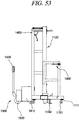
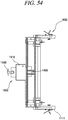
- An operation unit 1900 in accordance with an exemplary embodiment of the present disclosure will be described with reference to FIG. 53 and FIG. 54 .
- the operation unit 1900 may be provided in the back of the lower frame 1110. Further, the worker may move the foldable container folding/unfolding apparatus 20 through the operation unit 1900.
- the operation unit 1900 may include an operation motor (not illustrated), a battery unit 1910 configured to supply power to the operation motor, a wheel 1920 driven by the operation motor, and a control unit 1930. Therefore, the worker may manipulate the control unit 1930 to move the foldable container folding/unfolding apparatus 20 to a desired place.
- the battery unit 1910 may supply power to the motor 1420 of the front/rear side folding/unfolding unit 1400 and the driving unit 1520 of the up/down folding/unfolding unit 1500.
- the foldable container folding/unfolding apparatuses 20 may be positioned in front and back, respectively, of the foldable container 10.
- the lower fixing unit 1200 may be fixed to the lower corner fitting 120 of the foldable container 10 and the upper fixing unit 1300 may be fixed to the upper corner fitting 220 of the foldable container 10.
- the lower fixing piece 1210 of the lower fixing unit 1200 may be inserted into the insertion groove 120a formed in the lower corner fitting 120 and the upper fixing piece 1310 of the upper fixing unit 1300 may be inserted into the insertion groove 220a formed in the upper corner fitting 220. Then, the worker may fix the lower fixing unit 1200 to the lower corner fitting 120 by rotating the lower lever 1220 of the lower fixing unit 1200 and may fix the upper fixing unit 1300 to the upper corner fitting 220 by rotating the upper lever 1320 of the upper fixing unit 1300.
- the worker may release fixing members configured to fix the respective panels of the foldable container 10.
- the worker may operate the driving unit 1520 of the up/down folding/unfolding unit 1500 to move the upper panel 300 and the upper lateral panel 310 of the foldable container 10 upwards a predetermined distance.
- fixing devices configured to fix the front panel 400 and the rear panel 500 may be released.
- the wire 1410 of the front/rear side folding/unfolding unit 1400 may be connected to the rings 430 or the rod bar 460 provided on the front panel 400 or rear panel 500, and the motor 1420 of the front/rear side folding/unfolding unit 1400 may be operated to fold and unfold the front panel 400 or rear panel 500 (see FIG. 56 ).
- the wire 1410 of the front/rear side folding/unfolding unit 1400 may be fixed by hanging an end of the wire 1410 on the rings 430 or the rod bar 460 provided on the upper part of the front panel 400 or rear panel 500 of the foldable container 10 and the motor 1420 may be rotated to slowly unwind the wire 1410 and fold and unfold the front panel 400 and the rear panel 500 as being rotated.
- the worker may operate the driving unit 1520 of the up/down folding/unfolding unit 1500 to fold and unfold the upper panel 200 and the lateral panel 300 by slowly moving them downwards (see FIG. 57 and FIG. 58 ).
- the container folding/unfolding apparatus 20 may further include a control unit to automatically control the above-described process.
- the multiple foldable containers 10 may be folded and stacked and then transported and stored in a bundle.
Landscapes
- Engineering & Computer Science (AREA)
- Mechanical Engineering (AREA)
- Chemical & Material Sciences (AREA)
- Combustion & Propulsion (AREA)
- Transportation (AREA)
- Rigid Containers With Two Or More Constituent Elements (AREA)
Priority Applications (1)
| Application Number | Priority Date | Filing Date | Title |
|---|---|---|---|
| EP19218185.7A EP3653533A1 (de) | 2015-06-11 | 2016-06-10 | Vorrichtung zum falten und entfalten eines faltbarern behälters |
Applications Claiming Priority (3)
| Application Number | Priority Date | Filing Date | Title |
|---|---|---|---|
| KR1020150082544A KR101754192B1 (ko) | 2015-06-11 | 2015-06-11 | 접이식 컨테이너 |
| KR1020150091157A KR101754199B1 (ko) | 2015-06-26 | 2015-06-26 | 접이식 컨테이너 개폐장치 |
| PCT/KR2016/006167 WO2016200195A1 (ko) | 2015-06-11 | 2016-06-10 | 접이식 컨테이너 및 이를 개폐하는 장치 |
Related Child Applications (2)
| Application Number | Title | Priority Date | Filing Date |
|---|---|---|---|
| EP19218185.7A Division-Into EP3653533A1 (de) | 2015-06-11 | 2016-06-10 | Vorrichtung zum falten und entfalten eines faltbarern behälters |
| EP19218185.7A Division EP3653533A1 (de) | 2015-06-11 | 2016-06-10 | Vorrichtung zum falten und entfalten eines faltbarern behälters |
Publications (3)
| Publication Number | Publication Date |
|---|---|
| EP3296232A1 true EP3296232A1 (de) | 2018-03-21 |
| EP3296232A4 EP3296232A4 (de) | 2019-06-12 |
| EP3296232B1 EP3296232B1 (de) | 2021-08-11 |
Family
ID=57504080
Family Applications (2)
| Application Number | Title | Priority Date | Filing Date |
|---|---|---|---|
| EP16807835.0A Active EP3296232B1 (de) | 2015-06-11 | 2016-06-10 | Zusammenklappbarer behälter |
| EP19218185.7A Pending EP3653533A1 (de) | 2015-06-11 | 2016-06-10 | Vorrichtung zum falten und entfalten eines faltbarern behälters |
Family Applications After (1)
| Application Number | Title | Priority Date | Filing Date |
|---|---|---|---|
| EP19218185.7A Pending EP3653533A1 (de) | 2015-06-11 | 2016-06-10 | Vorrichtung zum falten und entfalten eines faltbarern behälters |
Country Status (5)
| Country | Link |
|---|---|
| US (2) | US10787311B2 (de) |
| EP (2) | EP3296232B1 (de) |
| JP (2) | JP6567093B2 (de) |
| CN (1) | CN107709194B (de) |
| WO (1) | WO2016200195A1 (de) |
Cited By (1)
| Publication number | Priority date | Publication date | Assignee | Title |
|---|---|---|---|---|
| EP3838799A4 (de) * | 2018-09-12 | 2022-05-11 | Korea Railroad Research Institute | Faltvorrichtung für einen faltbaren behälter und automatisches faltsystem damit |
Families Citing this family (13)
| Publication number | Priority date | Publication date | Assignee | Title |
|---|---|---|---|---|
| WO2018195578A1 (en) * | 2017-04-28 | 2018-11-01 | CEC Systems Pty Ltd | A collapsible intermodal container stacker and a stacking system |
| USD903317S1 (en) * | 2017-10-11 | 2020-12-01 | Icf Sa | Collapsible container |
| CZ2017780A3 (cs) * | 2017-12-05 | 2019-05-15 | Avex Steel Products s.r.o. | Zařízení pro otevírání a zavírání skládacích palet |
| CN111846649B (zh) * | 2019-04-28 | 2025-03-25 | 苏州优乐赛共享服务股份有限公司 | 一种端门收容结构及可折叠的集装箱 |
| CN111846650B (zh) * | 2019-04-28 | 2025-02-25 | 苏州优乐赛共享服务股份有限公司 | 一种可折叠的集装箱 |
| KR102367367B1 (ko) * | 2020-03-25 | 2022-02-24 | 씨스존 주식회사 | 물류용기 접이장치 |
| WO2022119806A1 (en) * | 2020-12-01 | 2022-06-09 | Crowley Government Services, Inc. | Collapsible shipping container |
| RU207180U1 (ru) * | 2021-06-11 | 2021-10-15 | Федеральное государственное бюджетное образовательное учреждение высшего образования «Государственный университет морского и речного флота имени адмирала С.О. Макарова» | Складной грузовой контейнер |
| CN115108092B (zh) * | 2022-03-18 | 2023-09-22 | 展一智能科技(东台)有限公司 | 一种输送定位系统及包装箱整理机 |
| DE102022107776B3 (de) * | 2022-04-01 | 2023-07-13 | Die Moebelbox UG (haftungsbeschränkt) | Faltbares Möbelstück und Verfahren dazu |
| CN114715480B (zh) * | 2022-05-04 | 2024-05-28 | 展一智能科技(苏州)有限公司 | 包装箱打开方法 |
| US20240239598A1 (en) * | 2023-01-18 | 2024-07-18 | Aero Marine Systems, Inc. | Collapsible Containment Vessel with Internal Baffles (CCViB) |
| US12330863B2 (en) * | 2023-01-18 | 2025-06-17 | Aero Marine Systems, Inc. | Modular bi-level storage and transport assembly with collapsible frame (MTA) |
Family Cites Families (35)
| Publication number | Priority date | Publication date | Assignee | Title |
|---|---|---|---|---|
| US4214669A (en) * | 1979-01-15 | 1980-07-29 | Mcquiston William W | Cargo container |
| US4388995A (en) * | 1981-06-08 | 1983-06-21 | Ahn Min H | Collapsible container |
| FR2509695A1 (fr) * | 1981-07-20 | 1983-01-21 | Extraco Anstalt | Container iso demontable-pliant avec possibilite de citerne souple |
| US4577772A (en) * | 1985-03-26 | 1986-03-25 | Bigliardi Juan B | Collapsible containers |
| KR900006297B1 (ko) | 1986-08-05 | 1990-08-28 | 도오시바 기까이 가부시끼가이샤 | 가동부재와 고정부재를 가지는 기계를 제어하기 위한 방법 및 장치 |
| ZA896229B (en) * | 1988-08-23 | 1990-05-30 | Geoffrey Raymond Richter | Collapsible container |
| JPH02123286A (ja) | 1988-10-31 | 1990-05-10 | Matsushita Refrig Co Ltd | 回転型圧縮機の支持装置 |
| JPH0431282A (ja) | 1990-05-29 | 1992-02-03 | Nec Corp | 移動用車輪内蔵型電子交換機のコンテナ |
| JPH0640100Y2 (ja) * | 1990-11-22 | 1994-10-19 | キムラユニティー株式会社 | 折り畳み式コンテナ |
| JP2650181B2 (ja) | 1993-03-24 | 1997-09-03 | 東洋製罐株式会社 | コンテナの自動折畳み装置 |
| US5351827B1 (en) * | 1993-06-25 | 1996-10-15 | Dometic Corp | Returnable packaging system for awnings |
| US5338136A (en) * | 1993-07-02 | 1994-08-16 | Hetchler Robert L | Cargo restraint apparatus |
| JP2942940B2 (ja) | 1993-10-21 | 1999-08-30 | トーヨーカネツ株式会社 | 蓋付コンテナ折り畳み装置 |
| JP3030297U (ja) * | 1996-04-17 | 1996-10-22 | 矢崎化工株式会社 | 折り畳み可能なコンテナの自動折り畳み装置 |
| US5862912A (en) * | 1997-04-24 | 1999-01-26 | Owens Corning Fiberglas Technology, Inc. | Package of building-panel products |
| KR100383060B1 (ko) | 1999-05-08 | 2003-05-09 | 박성규 | 절첩식 콘테이너 하우스 |
| US6296133B1 (en) * | 2000-06-02 | 2001-10-02 | Joseph L. Cobane | Container for vinyl siding |
| JP2002068136A (ja) * | 2000-08-29 | 2002-03-08 | Daishin Koki Kk | 折り畳みコンテナ連続展開立体化装置 |
| WO2005070790A1 (ja) | 2004-01-23 | 2005-08-04 | Tas Express Co., Ltd. | コンテナ |
| US7870970B2 (en) * | 2004-09-01 | 2011-01-18 | Collapsible Containers Pty Ltd. | Collapsible container |
| WO2010075607A1 (en) * | 2009-01-05 | 2010-07-08 | Foltainer International Pty Ltd | Collapsible containers |
| DE102009004795A1 (de) * | 2009-01-13 | 2010-07-15 | Texas Oil Capital Holding Corp., Sacramento | Verfahren zur Auffaltung eines Faltcontainers |
| US20120006816A1 (en) * | 2009-06-08 | 2012-01-12 | Turnquist T Cody | Collapsible container and method for erecting container |
| EP2616368B1 (de) * | 2010-09-13 | 2016-07-27 | Cargoshell Holding B.V. | Zusammenklappbarer frachtcontainer |
| AU2011365089B2 (en) * | 2011-07-22 | 2015-03-26 | Jung Sun Hong | Folding-type container |
| KR101406143B1 (ko) * | 2012-10-18 | 2014-06-12 | 주식회사 뉴텍엠 | 휴대형 기지국 설치 장치 |
| KR101258612B1 (ko) | 2013-01-10 | 2013-04-26 | 한국컨테이너풀 주식회사 | 접이식 컨테이너 |
| AU2013382188A1 (en) * | 2013-03-13 | 2015-11-05 | Sea Box Inc. | Collapsible stackable container with self-contained attachment members |
| US9108758B2 (en) * | 2013-03-13 | 2015-08-18 | James F. Brennan, Jr. | Collapsible stackable shipping container with self-contained attachment members |
| CN103253463A (zh) * | 2013-06-03 | 2013-08-21 | 吴江市三达五金工具厂 | 一种可拼接的折叠式集装箱 |
| KR101375806B1 (ko) * | 2013-10-07 | 2014-03-26 | 한국컨테이너풀 주식회사 | 슬라이딩 도어 방식의 접이식 컨테이너 |
| KR101423434B1 (ko) | 2013-11-14 | 2014-07-24 | 오씨아이 주식회사 | 분체 이송용 컨테이너 |
| KR101488384B1 (ko) | 2013-12-30 | 2015-02-02 | 한국철도기술연구원 | 접이식 컨테이너 |
| CN103848119A (zh) * | 2014-03-31 | 2014-06-11 | 上海采科实业有限公司 | 能够折叠到体积最小的集装箱 |
| CN107000931A (zh) * | 2014-09-19 | 2017-08-01 | 孔帕克特集装箱系统有限责任公司 | 堆叠的可折叠集装箱 |
-
2016
- 2016-06-10 JP JP2017564404A patent/JP6567093B2/ja active Active
- 2016-06-10 CN CN201680033917.9A patent/CN107709194B/zh active Active
- 2016-06-10 EP EP16807835.0A patent/EP3296232B1/de active Active
- 2016-06-10 US US15/580,894 patent/US10787311B2/en active Active
- 2016-06-10 WO PCT/KR2016/006167 patent/WO2016200195A1/ko not_active Ceased
- 2016-06-10 EP EP19218185.7A patent/EP3653533A1/de active Pending
-
2019
- 2019-04-26 JP JP2019085354A patent/JP6815436B2/ja active Active
- 2019-11-19 US US16/687,980 patent/US11618488B2/en active Active
Cited By (2)
| Publication number | Priority date | Publication date | Assignee | Title |
|---|---|---|---|---|
| EP3838799A4 (de) * | 2018-09-12 | 2022-05-11 | Korea Railroad Research Institute | Faltvorrichtung für einen faltbaren behälter und automatisches faltsystem damit |
| US12319492B2 (en) | 2018-09-12 | 2025-06-03 | Korea Railroad Research Institute | Foldable container folding device and automatic folding system comprising same |
Also Published As
| Publication number | Publication date |
|---|---|
| JP2018516817A (ja) | 2018-06-28 |
| WO2016200195A1 (ko) | 2016-12-15 |
| EP3296232A4 (de) | 2019-06-12 |
| US11618488B2 (en) | 2023-04-04 |
| US20180162635A1 (en) | 2018-06-14 |
| US10787311B2 (en) | 2020-09-29 |
| EP3296232B1 (de) | 2021-08-11 |
| JP6815436B2 (ja) | 2021-01-20 |
| CN107709194B (zh) | 2019-09-27 |
| JP6567093B2 (ja) | 2019-08-28 |
| US20200087059A1 (en) | 2020-03-19 |
| CN107709194A (zh) | 2018-02-16 |
| EP3653533A1 (de) | 2020-05-20 |
| JP2019163087A (ja) | 2019-09-26 |
Similar Documents
| Publication | Publication Date | Title |
|---|---|---|
| US11618488B2 (en) | Foldable container and apparatus for folding and unfolding the same | |
| US10206501B1 (en) | Folding storage unit | |
| KR101754192B1 (ko) | 접이식 컨테이너 | |
| AU2018341096B2 (en) | Foldable frame for containers and hinged member therefor | |
| EP3601105B1 (de) | Zusammenklappbarer intermodalbehälter und anordnung eines zusammenklappbaren intermodalbehälters | |
| US20220089359A1 (en) | Foldable container having corner locking structure | |
| JP6564590B2 (ja) | 廃棄物運搬用折り畳みコンテナ | |
| KR101754199B1 (ko) | 접이식 컨테이너 개폐장치 | |
| JP5047836B2 (ja) | ボックスパレット | |
| US12319492B2 (en) | Foldable container folding device and automatic folding system comprising same | |
| KR102005882B1 (ko) | 컨테이너 접철방법 | |
| KR102466048B1 (ko) | 관절형 연결장치 및 그것을 구비한 접이식 컨테이너 | |
| CN101327867B (zh) | 托盘箱及利用该托盘箱装载车门的方法 | |
| KR102002432B1 (ko) | 접이식 컨테이너 | |
| CN222432830U (zh) | 卷料托盘架 | |
| KR101577001B1 (ko) | 로킹 로드에 폴딩 힌지가 장착된 전면 벽체를 구비한 접이식 컨테이너 | |
| KR102002434B1 (ko) | 접이식 컨테이너의 프론트패널/리어패널 회전용 토션바 설치방법 | |
| KR102055327B1 (ko) | 사이드패널 접철용 토션바모듈을 구비한 접이식 컨테이너 | |
| JP2006347617A (ja) | 箱状コンテナの壁面構造 | |
| KR102002433B1 (ko) | 접이식 컨테이너의 프론트패널/리어패널 회전 지지부재 | |
| KR101577570B1 (ko) | 폴딩 힌지가 장착된 전면 벽체를 구비한 접이식 컨테이너 | |
| US20080083765A1 (en) | Portable container for assembly at point of use | |
| HK40020488B (en) | A collapsible intermodal container and a collapsible intermodal container assembly | |
| HK40020488A (en) | A collapsible intermodal container and a collapsible intermodal container assembly | |
| JP2005298003A (ja) | 運搬用パレットの荷崩れ防止装置 |
Legal Events
| Date | Code | Title | Description |
|---|---|---|---|
| STAA | Information on the status of an ep patent application or granted ep patent |
Free format text: STATUS: THE INTERNATIONAL PUBLICATION HAS BEEN MADE |
|
| PUAI | Public reference made under article 153(3) epc to a published international application that has entered the european phase |
Free format text: ORIGINAL CODE: 0009012 |
|
| STAA | Information on the status of an ep patent application or granted ep patent |
Free format text: STATUS: REQUEST FOR EXAMINATION WAS MADE |
|
| 17P | Request for examination filed |
Effective date: 20171208 |
|
| AK | Designated contracting states |
Kind code of ref document: A1 Designated state(s): AL AT BE BG CH CY CZ DE DK EE ES FI FR GB GR HR HU IE IS IT LI LT LU LV MC MK MT NL NO PL PT RO RS SE SI SK SM TR |
|
| AX | Request for extension of the european patent |
Extension state: BA ME |
|
| DAV | Request for validation of the european patent (deleted) | ||
| DAX | Request for extension of the european patent (deleted) | ||
| RIC1 | Information provided on ipc code assigned before grant |
Ipc: B65D 88/52 20060101AFI20181217BHEP Ipc: B65D 88/12 20060101ALI20181217BHEP |
|
| A4 | Supplementary search report drawn up and despatched |
Effective date: 20190510 |
|
| RIC1 | Information provided on ipc code assigned before grant |
Ipc: B65D 88/52 20060101AFI20190506BHEP Ipc: B65D 88/12 20060101ALI20190506BHEP |
|
| STAA | Information on the status of an ep patent application or granted ep patent |
Free format text: STATUS: EXAMINATION IS IN PROGRESS |
|
| 17Q | First examination report despatched |
Effective date: 20200430 |
|
| GRAP | Despatch of communication of intention to grant a patent |
Free format text: ORIGINAL CODE: EPIDOSNIGR1 |
|
| STAA | Information on the status of an ep patent application or granted ep patent |
Free format text: STATUS: GRANT OF PATENT IS INTENDED |
|
| INTG | Intention to grant announced |
Effective date: 20210312 |
|
| GRAS | Grant fee paid |
Free format text: ORIGINAL CODE: EPIDOSNIGR3 |
|
| GRAA | (expected) grant |
Free format text: ORIGINAL CODE: 0009210 |
|
| STAA | Information on the status of an ep patent application or granted ep patent |
Free format text: STATUS: THE PATENT HAS BEEN GRANTED |
|
| AK | Designated contracting states |
Kind code of ref document: B1 Designated state(s): AL AT BE BG CH CY CZ DE DK EE ES FI FR GB GR HR HU IE IS IT LI LT LU LV MC MK MT NL NO PL PT RO RS SE SI SK SM TR |
|
| REG | Reference to a national code |
Ref country code: CH Ref legal event code: EP |
|
| REG | Reference to a national code |
Ref country code: DE Ref legal event code: R096 Ref document number: 602016062096 Country of ref document: DE |
|
| REG | Reference to a national code |
Ref country code: IE Ref legal event code: FG4D Ref country code: AT Ref legal event code: REF Ref document number: 1419192 Country of ref document: AT Kind code of ref document: T Effective date: 20210915 |
|
| REG | Reference to a national code |
Ref country code: NL Ref legal event code: FP |
|
| REG | Reference to a national code |
Ref country code: LT Ref legal event code: MG9D |
|
| REG | Reference to a national code |
Ref country code: AT Ref legal event code: MK05 Ref document number: 1419192 Country of ref document: AT Kind code of ref document: T Effective date: 20210811 |
|
| PG25 | Lapsed in a contracting state [announced via postgrant information from national office to epo] |
Ref country code: LT Free format text: LAPSE BECAUSE OF FAILURE TO SUBMIT A TRANSLATION OF THE DESCRIPTION OR TO PAY THE FEE WITHIN THE PRESCRIBED TIME-LIMIT Effective date: 20210811 Ref country code: BG Free format text: LAPSE BECAUSE OF FAILURE TO SUBMIT A TRANSLATION OF THE DESCRIPTION OR TO PAY THE FEE WITHIN THE PRESCRIBED TIME-LIMIT Effective date: 20211111 Ref country code: AT Free format text: LAPSE BECAUSE OF FAILURE TO SUBMIT A TRANSLATION OF THE DESCRIPTION OR TO PAY THE FEE WITHIN THE PRESCRIBED TIME-LIMIT Effective date: 20210811 Ref country code: NO Free format text: LAPSE BECAUSE OF FAILURE TO SUBMIT A TRANSLATION OF THE DESCRIPTION OR TO PAY THE FEE WITHIN THE PRESCRIBED TIME-LIMIT Effective date: 20211111 Ref country code: PT Free format text: LAPSE BECAUSE OF FAILURE TO SUBMIT A TRANSLATION OF THE DESCRIPTION OR TO PAY THE FEE WITHIN THE PRESCRIBED TIME-LIMIT Effective date: 20211213 Ref country code: HR Free format text: LAPSE BECAUSE OF FAILURE TO SUBMIT A TRANSLATION OF THE DESCRIPTION OR TO PAY THE FEE WITHIN THE PRESCRIBED TIME-LIMIT Effective date: 20210811 Ref country code: FI Free format text: LAPSE BECAUSE OF FAILURE TO SUBMIT A TRANSLATION OF THE DESCRIPTION OR TO PAY THE FEE WITHIN THE PRESCRIBED TIME-LIMIT Effective date: 20210811 Ref country code: ES Free format text: LAPSE BECAUSE OF FAILURE TO SUBMIT A TRANSLATION OF THE DESCRIPTION OR TO PAY THE FEE WITHIN THE PRESCRIBED TIME-LIMIT Effective date: 20210811 Ref country code: SE Free format text: LAPSE BECAUSE OF FAILURE TO SUBMIT A TRANSLATION OF THE DESCRIPTION OR TO PAY THE FEE WITHIN THE PRESCRIBED TIME-LIMIT Effective date: 20210811 Ref country code: RS Free format text: LAPSE BECAUSE OF FAILURE TO SUBMIT A TRANSLATION OF THE DESCRIPTION OR TO PAY THE FEE WITHIN THE PRESCRIBED TIME-LIMIT Effective date: 20210811 |
|
| PG25 | Lapsed in a contracting state [announced via postgrant information from national office to epo] |
Ref country code: PL Free format text: LAPSE BECAUSE OF FAILURE TO SUBMIT A TRANSLATION OF THE DESCRIPTION OR TO PAY THE FEE WITHIN THE PRESCRIBED TIME-LIMIT Effective date: 20210811 Ref country code: LV Free format text: LAPSE BECAUSE OF FAILURE TO SUBMIT A TRANSLATION OF THE DESCRIPTION OR TO PAY THE FEE WITHIN THE PRESCRIBED TIME-LIMIT Effective date: 20210811 Ref country code: GR Free format text: LAPSE BECAUSE OF FAILURE TO SUBMIT A TRANSLATION OF THE DESCRIPTION OR TO PAY THE FEE WITHIN THE PRESCRIBED TIME-LIMIT Effective date: 20211112 |
|
| PG25 | Lapsed in a contracting state [announced via postgrant information from national office to epo] |
Ref country code: DK Free format text: LAPSE BECAUSE OF FAILURE TO SUBMIT A TRANSLATION OF THE DESCRIPTION OR TO PAY THE FEE WITHIN THE PRESCRIBED TIME-LIMIT Effective date: 20210811 |
|
| REG | Reference to a national code |
Ref country code: DE Ref legal event code: R097 Ref document number: 602016062096 Country of ref document: DE |
|
| PG25 | Lapsed in a contracting state [announced via postgrant information from national office to epo] |
Ref country code: SM Free format text: LAPSE BECAUSE OF FAILURE TO SUBMIT A TRANSLATION OF THE DESCRIPTION OR TO PAY THE FEE WITHIN THE PRESCRIBED TIME-LIMIT Effective date: 20210811 Ref country code: SK Free format text: LAPSE BECAUSE OF FAILURE TO SUBMIT A TRANSLATION OF THE DESCRIPTION OR TO PAY THE FEE WITHIN THE PRESCRIBED TIME-LIMIT Effective date: 20210811 Ref country code: RO Free format text: LAPSE BECAUSE OF FAILURE TO SUBMIT A TRANSLATION OF THE DESCRIPTION OR TO PAY THE FEE WITHIN THE PRESCRIBED TIME-LIMIT Effective date: 20210811 Ref country code: EE Free format text: LAPSE BECAUSE OF FAILURE TO SUBMIT A TRANSLATION OF THE DESCRIPTION OR TO PAY THE FEE WITHIN THE PRESCRIBED TIME-LIMIT Effective date: 20210811 Ref country code: CZ Free format text: LAPSE BECAUSE OF FAILURE TO SUBMIT A TRANSLATION OF THE DESCRIPTION OR TO PAY THE FEE WITHIN THE PRESCRIBED TIME-LIMIT Effective date: 20210811 Ref country code: AL Free format text: LAPSE BECAUSE OF FAILURE TO SUBMIT A TRANSLATION OF THE DESCRIPTION OR TO PAY THE FEE WITHIN THE PRESCRIBED TIME-LIMIT Effective date: 20210811 |
|
| PLBE | No opposition filed within time limit |
Free format text: ORIGINAL CODE: 0009261 |
|
| STAA | Information on the status of an ep patent application or granted ep patent |
Free format text: STATUS: NO OPPOSITION FILED WITHIN TIME LIMIT |
|
| 26N | No opposition filed |
Effective date: 20220512 |
|
| PG25 | Lapsed in a contracting state [announced via postgrant information from national office to epo] |
Ref country code: IT Free format text: LAPSE BECAUSE OF FAILURE TO SUBMIT A TRANSLATION OF THE DESCRIPTION OR TO PAY THE FEE WITHIN THE PRESCRIBED TIME-LIMIT Effective date: 20210811 |
|
| PG25 | Lapsed in a contracting state [announced via postgrant information from national office to epo] |
Ref country code: SI Free format text: LAPSE BECAUSE OF FAILURE TO SUBMIT A TRANSLATION OF THE DESCRIPTION OR TO PAY THE FEE WITHIN THE PRESCRIBED TIME-LIMIT Effective date: 20210811 |
|
| PG25 | Lapsed in a contracting state [announced via postgrant information from national office to epo] |
Ref country code: MC Free format text: LAPSE BECAUSE OF FAILURE TO SUBMIT A TRANSLATION OF THE DESCRIPTION OR TO PAY THE FEE WITHIN THE PRESCRIBED TIME-LIMIT Effective date: 20210811 |
|
| REG | Reference to a national code |
Ref country code: CH Ref legal event code: PL |
|
| REG | Reference to a national code |
Ref country code: BE Ref legal event code: MM Effective date: 20220630 |
|
| GBPC | Gb: european patent ceased through non-payment of renewal fee |
Effective date: 20220610 |
|
| PG25 | Lapsed in a contracting state [announced via postgrant information from national office to epo] |
Ref country code: LU Free format text: LAPSE BECAUSE OF NON-PAYMENT OF DUE FEES Effective date: 20220610 Ref country code: LI Free format text: LAPSE BECAUSE OF NON-PAYMENT OF DUE FEES Effective date: 20220630 Ref country code: IE Free format text: LAPSE BECAUSE OF NON-PAYMENT OF DUE FEES Effective date: 20220610 Ref country code: FR Free format text: LAPSE BECAUSE OF NON-PAYMENT OF DUE FEES Effective date: 20220630 Ref country code: CH Free format text: LAPSE BECAUSE OF NON-PAYMENT OF DUE FEES Effective date: 20220630 |
|
| PG25 | Lapsed in a contracting state [announced via postgrant information from national office to epo] |
Ref country code: GB Free format text: LAPSE BECAUSE OF NON-PAYMENT OF DUE FEES Effective date: 20220610 Ref country code: BE Free format text: LAPSE BECAUSE OF NON-PAYMENT OF DUE FEES Effective date: 20220630 |
|
| PG25 | Lapsed in a contracting state [announced via postgrant information from national office to epo] |
Ref country code: HU Free format text: LAPSE BECAUSE OF FAILURE TO SUBMIT A TRANSLATION OF THE DESCRIPTION OR TO PAY THE FEE WITHIN THE PRESCRIBED TIME-LIMIT; INVALID AB INITIO Effective date: 20160610 |
|
| PG25 | Lapsed in a contracting state [announced via postgrant information from national office to epo] |
Ref country code: MK Free format text: LAPSE BECAUSE OF FAILURE TO SUBMIT A TRANSLATION OF THE DESCRIPTION OR TO PAY THE FEE WITHIN THE PRESCRIBED TIME-LIMIT Effective date: 20210811 Ref country code: CY Free format text: LAPSE BECAUSE OF FAILURE TO SUBMIT A TRANSLATION OF THE DESCRIPTION OR TO PAY THE FEE WITHIN THE PRESCRIBED TIME-LIMIT Effective date: 20210811 |
|
| PG25 | Lapsed in a contracting state [announced via postgrant information from national office to epo] |
Ref country code: MT Free format text: LAPSE BECAUSE OF FAILURE TO SUBMIT A TRANSLATION OF THE DESCRIPTION OR TO PAY THE FEE WITHIN THE PRESCRIBED TIME-LIMIT Effective date: 20210811 |
|
| PGFP | Annual fee paid to national office [announced via postgrant information from national office to epo] |
Ref country code: NL Payment date: 20250409 Year of fee payment: 10 |
|
| PGFP | Annual fee paid to national office [announced via postgrant information from national office to epo] |
Ref country code: DE Payment date: 20250402 Year of fee payment: 10 |
|
| PG25 | Lapsed in a contracting state [announced via postgrant information from national office to epo] |
Ref country code: TR Free format text: LAPSE BECAUSE OF FAILURE TO SUBMIT A TRANSLATION OF THE DESCRIPTION OR TO PAY THE FEE WITHIN THE PRESCRIBED TIME-LIMIT Effective date: 20210811 |