EP3296232B1 - Zusammenklappbarer behälter - Google Patents
Zusammenklappbarer behälter Download PDFInfo
- Publication number
- EP3296232B1 EP3296232B1 EP16807835.0A EP16807835A EP3296232B1 EP 3296232 B1 EP3296232 B1 EP 3296232B1 EP 16807835 A EP16807835 A EP 16807835A EP 3296232 B1 EP3296232 B1 EP 3296232B1
- Authority
- EP
- European Patent Office
- Prior art keywords
- panel
- shape
- lateral
- foldable container
- frame
- Prior art date
- Legal status (The legal status is an assumption and is not a legal conclusion. Google has not performed a legal analysis and makes no representation as to the accuracy of the status listed.)
- Active
Links
Images


Classifications
-
- B—PERFORMING OPERATIONS; TRANSPORTING
- B65—CONVEYING; PACKING; STORING; HANDLING THIN OR FILAMENTARY MATERIAL
- B65D—CONTAINERS FOR STORAGE OR TRANSPORT OF ARTICLES OR MATERIALS, e.g. BAGS, BARRELS, BOTTLES, BOXES, CANS, CARTONS, CRATES, DRUMS, JARS, TANKS, HOPPERS, FORWARDING CONTAINERS; ACCESSORIES, CLOSURES, OR FITTINGS THEREFOR; PACKAGING ELEMENTS; PACKAGES
- B65D88/00—Large containers
- B65D88/52—Large containers collapsible, i.e. with walls hinged together or detachably connected
- B65D88/522—Large containers collapsible, i.e. with walls hinged together or detachably connected all side walls hingedly connected to each other or to another component of the container
- B65D88/524—Large containers collapsible, i.e. with walls hinged together or detachably connected all side walls hingedly connected to each other or to another component of the container and one or more side walls being foldable along an additional median line
-
- B—PERFORMING OPERATIONS; TRANSPORTING
- B62—LAND VEHICLES FOR TRAVELLING OTHERWISE THAN ON RAILS
- B62B—HAND-PROPELLED VEHICLES, e.g. HAND CARTS OR PERAMBULATORS; SLEDGES
- B62B3/00—Hand carts having more than one axis carrying transport wheels; Steering devices therefor; Equipment therefor
- B62B3/02—Hand carts having more than one axis carrying transport wheels; Steering devices therefor; Equipment therefor involving parts being adjustable, collapsible, attachable, detachable or convertible
-
- B—PERFORMING OPERATIONS; TRANSPORTING
- B65—CONVEYING; PACKING; STORING; HANDLING THIN OR FILAMENTARY MATERIAL
- B65D—CONTAINERS FOR STORAGE OR TRANSPORT OF ARTICLES OR MATERIALS, e.g. BAGS, BARRELS, BOTTLES, BOXES, CANS, CARTONS, CRATES, DRUMS, JARS, TANKS, HOPPERS, FORWARDING CONTAINERS; ACCESSORIES, CLOSURES, OR FITTINGS THEREFOR; PACKAGING ELEMENTS; PACKAGES
- B65D88/00—Large containers
- B65D88/02—Large containers rigid
- B65D88/12—Large containers rigid specially adapted for transport
- B65D88/121—ISO containers
-
- B—PERFORMING OPERATIONS; TRANSPORTING
- B65—CONVEYING; PACKING; STORING; HANDLING THIN OR FILAMENTARY MATERIAL
- B65D—CONTAINERS FOR STORAGE OR TRANSPORT OF ARTICLES OR MATERIALS, e.g. BAGS, BARRELS, BOTTLES, BOXES, CANS, CARTONS, CRATES, DRUMS, JARS, TANKS, HOPPERS, FORWARDING CONTAINERS; ACCESSORIES, CLOSURES, OR FITTINGS THEREFOR; PACKAGING ELEMENTS; PACKAGES
- B65D88/00—Large containers
- B65D88/52—Large containers collapsible, i.e. with walls hinged together or detachably connected
- B65D88/522—Large containers collapsible, i.e. with walls hinged together or detachably connected all side walls hingedly connected to each other or to another component of the container
-
- B—PERFORMING OPERATIONS; TRANSPORTING
- B66—HOISTING; LIFTING; HAULING
- B66D—CAPSTANS; WINCHES; TACKLES, e.g. PULLEY BLOCKS; HOISTS
- B66D3/00—Portable or mobile lifting or hauling appliances
- B66D3/18—Power-operated hoists
Definitions
- the present disclosure relates to a foldable container.
- a container in general, includes four corner beams as supports and panels each having a predetermined area as six surfaces, i.e., front, rear, left, right, top, and bottom surfaces, between the supports and interlocked and assembled by welding or using a fastening means such as rivet to form a space therein for transport or storage of freight.
- a conventional container has a fixed space regardless of whether freight is loaded or not, and, thus, even when an empty container without freight is transported, the empty container needs to be transported as mounted on a freight truck in spite of being light in weight like a container loaded with freight. Therefore, a single freight truck cannot transport multiple empty containers stacked thereon.
- containers when transported on a ship in a harbor, containers are stacked in multiple stages. Like containers loaded with freight, empty containers are also transported as stacked and thus occupy a lot of space of the ship, which results in an increase in cost of transport.
- the containers are stacked in multiple stages. Since the containers are stacked in their original form, they require a wide storage place.
- general containers for shipping freight are high-weight and large-sized structure unlike lightweight plastic containers and thus can be damaged or deformed by load and collision when stacked.
- Korean Patent Laid-open Publication No. 10-1999-0064773 discloses a foldable container house in which a front plate and a rear plate provided as a pair of foldable unit members between top and bottom plates formed as single boards to cover a front side and a rear side, respectively, and upper portions of lateral plates are formed as free ends and lower portions thereof are connected to the bottom plate with pivot pins, and, thus, the front and rear plates and the lateral plates are foldable to each other.
- Foldable containers have previously been proposed and examples are disclosed in WO 2006/024104 A1 , WO 2014/142824 A1 , US 2012/006816 A1 and DE 10 2009 004 795 A1 .
- WO 2006/024104 A1 , WO 2014/142824 A1 , US 2012/006816 A1 and DE 10 2009 004 795 A1 have a problem with folding side panels by pushing the side panels with a strong force, as the weight of the upper side panel applies to the top of the lower side panel.
- WO 2006/024104 A1 discloses a configuration in which the hinge is hinged on the upper side panel and the lower side panel respectively, but does not disclose a configuration in which the upper side panel is moved a certain distance in the upper direction by the hinge.
- WO 2014/142824 A1 discloses the connection of the upper side panel and the lower side panel by a typical hinge configuration.
- the applicant of the present invention worked hard to apply various improvements to the defective parts of the conventional technique developed by the applicant of the present invention and thus developed a folding container whose quality has been enhanced.
- the present invention is to provide a foldable container in which the side panel folds after the upper side panel moves a certain distance in the upper direction by the sliding joint, allowing the side panel to be folded with small force.
- the present invention is to provide the foldable container in which, when the front panel and the rear panel are folded toward the inside of the foldable container, the upper panel is moved a certain distance in the upper direction by the sliding joint, allowing the front panel and the rear panel to be folded without interference in the upper panel.
- the present invention is to provide the foldable container in which is the front panel can be fixed stably since the protrusion on the upper surface of the front panel is inserted into the recession on the lower surface of the upper panel, and when the front panel is folded toward the inside of the foldable container, the upper panel is moved upwards a predetermined distance by the sliding joint and the protrusion gets out of the recession accordingly, and, thus, the front panel can be folded.
- the present disclosure is conceived to solve the above-described problem of the conventional technology and provides a foldable container which makes it possible to fold and stack empty containers without freight and then store and transport them and thus minimize a space required for storage and transport and also reduce costs related thereto.
- the present disclosure provides a foldable container which makes it possible to endure a load of stacked containers when multiple unfolded or folded containers are stacked.
- a foldable container includes: a lower panel; an upper panel provided in parallel with the lower panel; first and second lateral panels including upper lateral panels of which upper end is respectively hinge-connected to the upper panel to be rotatable along a longitudinal direction of the upper panel and lower lateral panels of which lower end is respectively hinge-connected to the lower panel to be rotatable along a longitudinal direction of the lower panel and positioned under the upper lateral panels and which are configured to be folded toward the inside of the foldable container; and front and rear panels connected to the lower panel to be rotatable along a transverse direction of the lower panel, wherein the first and second lateral panels further include one or more sliding joints connecting the upper lateral panel and the lower lateral panel such that the upper panel is moved upwards, the upper lateral panels are moved upwards a predetermined distance by the sliding joint and the front panel and the rear panel are folded inward of the foldable container and then the first and second lateral panel are folded, and the sliding joint includes a first fixing unit connected to the upper lateral panel,
- empty containers without freight among containers used for freight transport can be folded and then stacked, and, thus, the efficiency in storage and transport can be greatly increased.
- folded containers can be stacked and then stored and transported in batches, and, thus, the efficiency in maintenance of containers and a life of the containers can be increased.
- an upper side sill and an upper reinforcing piece combined with a longitudinal frame of an upper panel and a lower side sill and a lower reinforcing piece combined with a longitudinal frame of a lower panel are provided, and, thus, it is possible to endure a vertical load of stacked containers, a freight load applied when freight is loaded, and lifting of an upper part of a container.
- connection to or “coupled to” that is used to designate a connection or coupling of one element to another element includes both a case that an element is “directly connected or coupled to” another element and a case that an element is “electronically connected or coupled to” another element via still another element.
- the term "on” that is used to designate a position of one element with respect to another element includes both a case that the one element is adjacent to the another element and a case that any other element exists between these two elements.
- the term “comprises or includes” and/or “comprising or including” used in the document means that one or more other components, steps, operation and/or existence or addition of elements are not excluded in addition to the described components, steps, operation and/or elements unless context dictates otherwise.
- the term “about or approximately” or “substantially” is intended to have meanings close to numerical values or ranges specified with an allowable error and intended to prevent accurate or absolute numerical values disclosed for understanding of the present disclosure from being illegally or unfairly used by any unconscionable third party.
- the term “step of” does not mean “step for”.
- the present disclosure relates to a foldable container.
- FIG. 1 is a perspective view of a foldable container in accordance with an exemplary embodiment of the present disclosure
- FIG. 2 is a side view of the foldable container in accordance with an exemplary embodiment of the present disclosure
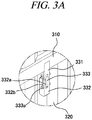
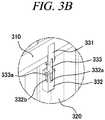
- FIG. 3 and FIG. 4 are enlarged views of a portion A in FIG. 1 and exemplary operation diagrams of a sliding joint in accordance with an exemplary embodiment of the present disclosure
- FIG. 5 provides a partially enlarged view and a partial cross-sectional view of a lower panel in accordance with an exemplary embodiment of the present disclosure
- FIG. 6 provides exemplary operation diagrams of a cover portion in accordance with an exemplary embodiment of the present disclosure
- FIG. 1 is a perspective view of a foldable container in accordance with an exemplary embodiment of the present disclosure
- FIG. 2 is a side view of the foldable container in accordance with an exemplary embodiment of the present disclosure
- FIG. 3 and FIG. 4 are enlarged views of a portion A in FIG. 1 and exemplary operation diagrams of a sliding joint in accord
- FIG. 7 provides diagrams illustrating a hinge portion of a front panel in accordance with an exemplary embodiment of the present disclosure
- FIG. 8 provides a partial perspective view and a partially see-through view of a lower edge of the foldable container in accordance with an exemplary embodiment of the present disclosure
- FIG. 9 is a diagram provided to illustrate an operating of folding a front panel illustrated in FIG. 8
- FIG. 10 is a diagram provided to explain a locking device storage unit in accordance with an exemplary embodiment of the present disclosure
- FIG. 11 is a diagram provided to explain a configuration for fixing a front panel and a rear panel to an upper panel in accordance with an exemplary embodiment of the present disclosure
- FIG. 12 is a diagram provided to explain a configuration for fixing a front panel and a rear panel to an upper panel in accordance with another exemplary embodiment of the present disclosure
- FIG. 13 is a side view of a configuration fixed by the front panel and the rear panel illustrated in FIG. 11 and FIG. 12
- FIG. 14 is a diagram provided to explain a member for fixing a lateral panel in accordance with an exemplary embodiment of the present disclosure
- FIG. 15 is a partial cross-sectional perspective view of the foldable container in accordance with an exemplary embodiment of the present disclosure
- FIG. 16 is an enlarged view of a portion D in FIG. 15
- FIG. 17 provides exemplary operation diagrams of a lateral panel supporting unit in accordance with an exemplary embodiment of the present disclosure
- FIG. 18 provides enlarged views of portions B and C in FIG. 1
- FIG. 19 is a diagram provided to explain an upper reinforcing piece and a lower reinforcing piece in accordance with an exemplary embodiment of the present disclosure
- FIG. 20 is a side view of the foldable container in accordance with an exemplary embodiment of the present disclosure
- FIG. 21A is a cross-sectional view taken along a line E-E' in FIG. 20
- FIG. 21B is a cross-sectional view taken along a line F-F' in FIG. 20
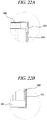
- FIG. 22 provides enlarged views of portions G and H in FIG. 21A
- FIG. 23 provides enlarged views of portions I and J in FIG. 21B
- FIG. 24 is a cross-sectional perspective view taken along a line E-E' in FIG. 21
- FIG. 25A is an enlarged view of a portion K in FIG. 24
- FIG. 25B is a diagram provided to explain a fixing member of a lower lateral panel
- FIG. 26 provides cross-sectional views of the foldable container in accordance with an exemplary embodiment of the present disclosure
- FIG. 27 provides enlarged views of a portion L in FIG. 26
- FIG. 28 provides enlarged views of a portion M in FIG. 26
- FIG. 29 provides enlarged views of a portion N in FIG. 26
- FIG. 30 provides diagrams to explain a panel connection protection unit in accordance with an exemplary embodiment of the present disclosure
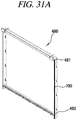
- FIG. 31 provides perspective view of a frame of a front panel in accordance with an exemplary embodiment of the present disclosure
- FIG. 32 is a diagram provided to explain a rod bar in accordance with an exemplary embodiment of the present disclosure
- FIG. 33 is a diagram provided to explain a panel connection unit in accordance with an exemplary embodiment of the present disclosure.
- present foldable container 10 a foldable container 10 according to an exemplary embodiment of the present disclosure (hereinafter, referred to as "present foldable container 10") will be described.
- the present foldable container 10 includes a lower panel 100, an upper panel 200 provided in parallel with the lower panel 100, first and second lateral panels 301 and 302 of which upper and lower ends are respectively connected to the upper panel 200 and the lower panel 100 to be rotatable along a longitudinal direction of the upper panel 200 and the lower panel 100 and which are configured to be folded toward the inside of the foldable container 10, and a front panel 400 and a rear panel 500 connected to the lower panel 100 to be rotatable along a transverse direction of the lower panel 100.
- the longitudinal direction may refer to the 8 o'clock direction and the 2 o'clock direction in FIG. 1
- the transverse direction may refer to the 4 o'clock direction and the 10 o'clock direction in FIG. 1 .
- first lateral panel 301 and the second lateral panel 302 are positioned on lateral sides, respectively, between the upper panel 200 and the lower panel 100 and include the same components and are symmetrically provided. Therefore, the first lateral panel 301 and the second lateral panel 302 will not be separately described, but will be referred to and described as a lateral panel 300.
- the lateral panel 300 includes an upper lateral panel 310 hinge-connected to the upper panel 200, a lower lateral panel 320 positioned under the upper lateral panel 310 and hinge-connected to the lower panel 100, and one or more sliding joints 330 connecting the upper lateral panel 310 and the lower lateral panel 320.
- the upper lateral panel 310 may be hinge-connected to the upper panel 200 to be rotatable.
- at least one hinge portion 310a of the upper lateral panel 310 may be positioned at an edge of an upper inside of the upper lateral panel 310 and the hinge portion 310a of the upper lateral panel 310 may be connected to a longitudinal lower part of the upper panel 200, and the upper lateral panel 310 may be folded by being rotated toward the inside of the foldable container 10 around the hinge portion 310a of the upper lateral panel 310.
- the inside may refer to a space in the foldable container 10 where freight is loaded.
- the lower lateral panel 320 may be positioned under the upper lateral panel 310 and a lower part thereof may be hinge-connected to the lower panel 100 to be rotatable.
- at least one hinge portion 320a of the lower lateral panel 320 may be positioned at an edge of a lower inside of the lower lateral panel 320 and the hinge portion 320a of the lower lateral panel 320 may be connected to a longitudinal upper part of the lower panel 100, and the lower lateral panel 320 may be folded by being rotated toward the inside of the foldable container 10 around the hinge portion 320a of the lower lateral panel 320.
- the upper lateral panel 310 is moved upwards a predetermined distance and then the lateral panel 300 is folded.
- the upper lateral panel 310 and the lower lateral panel 320 are connected by one or more sliding joints 330.
- the sliding joint 330 includes a first fixing unit 331 connected to the upper lateral panel 310, a second fixing unit 332 connected to the lower lateral panel 320, and a link unit 333 of which one side is hinge-connected to the first fixing unit 331 and the other side is hinge-connected to the second fixing unit 332 to be slidable.
- an upper part of the first fixing unit 331 may be connected to a lower part of an outer surface of the upper lateral panel 310 and a lower part of the first fixing unit 331 may be hinge-connected to an upper part of the link unit 333.
- the second fixing unit 332 may be connected to an upper part of an outer surface of the lower lateral panel 320 and an upper part of the second fixing unit 332 may be connected to a lower part of the link unit 333.
- the upper part of the second fixing unit 332 may include a sliding dent 332a which is dented for the link unit 333 to be inserted therein, and a sliding groove 332b having a predetermined length in a vertical direction may be formed outwards in each of inner surfaces of the sliding dent 332a.
- the upper part of the link unit 333 may be hinge-connected to the lower part of the first fixing unit 331 and a sliding pine 333a may be positioned on the lower part thereof, and the sliding pin 333a may be inserted into the sliding groove 332b and then connected to the second fixing part 332 to be movable and rotatable in a vertical direction along the sliding groove 332b.
- the upper lateral panel 310 is moved upwards a predetermined distance and the link unit 333 is moved upwards the same distance along the sliding groove 332b accordingly.
- the link unit 333 is moved toward an inner lower part of the foldable container 10 at the same time when the lower part of the first fixing unit 331 and the upper part of the second fixing unit 332 are hinge-connected to the upper part and the lower part of the link unit 333, respectively, and, thus, the upper lateral panel 310 and the lower lateral panel 320 can be folded.
- the lower panel 100 in accordance with an exemplary embodiment of the present disclosure will be described with reference to FIG. 5 and FIG. 6 .
- a step portion 110 which is stepped lower than the upper surface of the lower panel 100 may be formed.
- the step portion 110 may include a step surface 111 formed in parallel with the upper surface of the lower panel 100 and a step sill surface 112 formed perpendicularly to the step surface 111 and connected to the upper surface and the step surface 111.
- the lower panel 100 may include a cover portion 140 which can cover the step portion 110 of the lower panel 100.
- hinge portions 141 of the cover portion 140 may be positioned at both ends of the cover potion 140 in a transverse direction and the hinge portions 141 of the cover portion 140 may be connected to the lateral panel 300 and rotated around an edge where the step sill surface 112 and the upper surface of the lower panel 100 meet, as illustrated in FIG. 5 and FIG. 6 .
- the cover portion 140 is not limited thereto and may be hinge-connected to an upper part of the step sill surface 112 and rotated around the edge where the step sill surface 112 and the upper surface of the lower panel 100 meet.
- the front panel 400 and the rear panel 500 are positioned on a front side and a rear side, respectively, between the upper panel 200 and the lower panel 100 and include the same components and are symmetrically provided. Therefore, an explanation of the rear panel 500 will be omitted and only the front panel 400 will be explained.
- the front panel 400 may be manufactured in the form of a door and the rear panel 500 may be manufactured in the form of a wall.
- the front panel 400 may be connected to be rotatable toward the inside of the foldable container 10.
- the front panel 400 in accordance with an exemplary embodiment of the present disclosure will be described with reference to FIG. 7 .
- the front panel 400 may be hinge-connected to the step portion 110.
- a hinge portion 420 of the front panel 400 is positioned at an inner lower edge thereof and the hinge portion 420 of the front panel 400 is positioned at the step portion 110 and the front panel 400 can be folded around the hinge portion 420 of the front panel 400 toward the inside of the foldable container 10.
- the cover portion 140 is rotated first, and then the front panel 400 can be folded inwards.
- the front panel 400 when the front panel 400 is hinge-connected to the step portion 110 and thus folded toward the inside of the foldable container 10, the front panel 400 can be folded without interference in a bottom surface of the lower panel 100 and a step with respect to the upper surface of the lower panel 100 can be eliminated and the introduction of external foreign materials into the foldable container 10 can be suppressed while a door in the front panel 400 is maintained in size.
- the hinge portion 420 of the front panel 400 is not exposed to the outside but formed flat without unevenness on the upper surface of the lower panel 100.
- the front panel 400 and the rear panel 500 include rings 430 on their upper part, and, thus, the front panel 400 and the rear panel 500 can be rotated to be folded and unfolded by connecting a wire of the container folding/unfolding apparatus 20 to be described later to the rings 430.
- the front panel 400 and the rear panel 500 may further include a rod bar 460 connected to their upper part.
- one end of the rod bar 460 may be connected to the upper part of the front panel 400 or rear panel 500 to be rotatable and the other end thereof may be connected to the wire of the container folding/unfolding apparatus 20.
- a worker can connect the wire for rotating the front panel 400 or rear panel 500 to the other end of the rod bar 460 without entering the foldable container 10. Therefore, it is possible to suppress the risk of safety accident.
- the front panel 400 in accordance with another exemplary embodiment of the present disclosure will be described with reference to FIG. 8 and FIG. 9 .
- the front panel 400 includes a rotation protrusion 450 on a lower part of a lateral frame and a rotation recession 321 formed on an inner surface of the lateral panel 300, and, thus, the rotation protrusion 450 can be connected to the rotation recession 321 by being inserted into the rotation recession 321 to be rotatable.
- the front panel 400 includes the rotation protrusion 450 on the lower part of the lateral frame, and the rotation recession 321 into which the rotation protrusion 450 is inserted is dented to have a " " shape on the inner surface of the lateral panel 300, and if the front panel 400 is folded, the rotation protrusion 450 can be moved upwards within the rotation recession 321 and then the front panel 400 can be folded.
- the step surface 111 of the lower panel 100 may include a locking device storage unit 111a which is dented downwards and configured to store a container locking device capable of connecting edges of the foldable container 10.
- the locking device storage unit 111a is a place to store a device connecting the container 10 and the container 10 and is dented downwards on the step surface 111 and divided by partitions to store multiple container locking devices. Further, as illustrated in FIG. 10 , the locking device storage unit 111a may store four container locking devices therein to connect the respective edges of the foldable container 10, but is not limited thereto and may store multiple locking devices therein.
- a configuration in which the front panel 400 is fixed to the upper panel 200 will be described with reference to FIG. 11 to FIG. 13 .
- the front panel may include a protrusion 410 protruded on an upper surface of an upper frame of the front panel 400
- the upper panel 20 may include a recession 210 positioned on a lower surface of a transverse frame of the upper panel 200 and dented for the protrusion 410 to be inserted therein.
- the front panel 400 can be fixed without being folded toward the inside of the foldable container 10 since the protrusion 410 on the upper surface of the upper frame of the front panel 400 is inserted into the recession 210 on the lower surface of the transverse frame of the upper panel 200.
- the front panel 400 is folded toward the inside of the foldable container 10, the upper panel 200 is moved upwards a predetermined distance and the protrusion 410 gets out of the recession 210 accordingly, and, thus, the front panel 400 can be folded.
- a recession 440 may be dented on the upper surface of the upper frame of the front panel 400 and a protrusion 240 may be protruded on the lower surface of the transverse frame of the upper panel 200.
- the protrusions 240 and 410 may be formed into a cylindrical shape of which an upper edge is chamfered and thus can be easily inserted into the recessions 210 and 440.
- a folding fixing unit 340 and a lateral panel reinforcing unit 350 will be described with reference to FIG. 14 .
- the folding fixing unit 340 can function to fix the upper lateral panel 310 and the lower lateral panel 320 not to be folded toward the inside of the foldable container 10 when the foldable container 10 is used. Further, one or more folding fixing units 340 may be provided.
- the folding fixing unit 340 may be positioned on an inner side of the lateral panel, and, thus, it is possible to suppress the release of the folding fixing unit 340 from the outside and folding of the lateral panel 300.
- the folding fixing unit 340 may include a screw unit 341 protruded inwards on a lower inner surface of the upper lateral panel 310, a screw insertion unit 342 of one-side open type formed on the lateral panel reinforcing unit 350 positioned on an upper part of the lower lateral panel 320, and a bolt 343 combined with the screw unit 341.
- the one-side open type may refer to a "U" shape with an open top, so that the upper lateral panel 310 can be moved upwards even when the screw unit 341 is inserted.
- the screw unit 341 is fixed to the lower inner surface of the upper lateral panel 310, and the screw unit 341 is inserted into the screw insertion unit 342 formed on the lateral panel reinforcing unit 350 positioned on the upper part of the lower lateral panel 320 and the bolt 343 is engaged with the screw unit 341, and, thus, an upper outer surface of the lower lateral panel 320 is closely fixed to the inner surface of the upper lateral panel 310. Therefore, the upper lateral panel 310 and the lower lateral panel 320 are not folded toward the inside of the foldable container 10. Further, when the foldable container 10 is folded, the upper lateral panel 310 and the lower lateral panel 320 can be folded by removing the bolt 343.
- the lateral panel reinforcing unit 350 may be positioned along a longitudinal direction between the upper lateral panel 310 and the lower lateral panel 320.
- the lateral panel reinforcing unit 350 may support the upper lateral panel 310 hinge-connected to the upper panel 200 and enable the lateral panel 300 to be stably fixed together with the folding fixing unit 340.
- the lateral panel reinforcing unit 350 may be connected to the upper part of the lower lateral panel 320 along a longitudinal direction as a member of which a cross-section has a " ⁇ " shape, but is not limited thereto, and may be connected thereto as a member having a " ⁇ " shape, " " shape, or " “ shape.
- a lateral panel supporting unit 360 in accordance with an exemplary embodiment of the present disclosure will be described with reference to FIG. 15 to FIG. 17 .
- a one end of the lateral panel supporting unit 360 may be hinge-connected to the upper part of the lower lateral panel 320 and when the lateral panel 300 is folded, the other end thereof may be in contact with the upper surface of the lower panel 100. Further, multiple lateral panel supporting units 360 may be provided along a longitudinal direction.
- the lateral panel supporting unit 360 may be positioned within the lateral panel reinforcing unit 350 as illustrated in FIG. 16A , but is not limited thereto and may be positioned on the upper part of the lower lateral panel 320.
- the lateral panel supporting unit 360 may be positioned not to protrude toward the inside of the lateral panel 300.
- the lateral panel supporting unit 360 may be rotated around its one side to protrude in a direction perpendicular to the inner surface of the lateral panel 300.
- the other side of the lateral panel supporting unit 360 is in contact with the upper surface of the lower panel 100 and thus can support the weight of the lateral panel 300. With this configuration, it is possible to suppress deformation of the upper panel 200 or lateral panel 300 by weight.
- An upper corner fitting 220 and a lower corner fitting 120 are provided at corners of the upper panel 200 and the lower panel 100, respectively.
- the upper corner fitting 220 and the lower corner fitting 120 are provided to endure a load applied when the foldable containers 10 are stacked in multiple stages, and when the foldable containers 10 are folded and stacked and then transported in batches, the corner fittings of the containers 10 are fixed to suppress unfolding of the foldable containers 10.
- the foldable container 10 may include the upper reinforcing piece 230 and the lower reinforcing piece 130 to fix the folded foldable container 10 not to be unfolded and endure a load applied when multiple containers are stacked on the folded foldable container 10.
- the upper reinforcing piece 230 may be extended downwards from the upper corner fitting 220 and may include a fastening piece 231.
- the lower reinforcing piece 130 may be extended upwards from the lower corner fitting 120 and may include a fastening piece fixing unit 131 to which the fastening piece 231 is inserted and fastened.
- An extension length of the upper reinforcing piece 230 and the lower reinforcing piece 130 may be appropriately selected in consideration of a thickness of the folded container.
- the upper reinforcing piece 230 and the lower reinforcing piece 130 may be extended to an appropriate length, so that when the foldable container is fully folded, the fastening piece 231 can be inserted into the fastening piece fixing unit 131 and fastening holes 231a formed in the fastening piece 231 can match up with fastening holes f formed in the fastening piece fixing unit 131, respectively.
- the upper reinforcing piece 230 is safely placed on the lower reinforcing piece 130 and the fastening piece 231 is inserted into the fastening piece fixing unit 131 at the same time, and then, the fastening piece 231 is fixed to the fastening piece fixing unit 131 by allowing fastening members to pass through the fastening holes 231a formed in the fastening piece 231 and the fastening holes 132 formed in the fastening piece fixing unit 131. Therefore, it is possible to endure a load applied when the containers 10 are stacked in multiple stages and thus possible to suppress damage to the containers 10 by weight, and also possible to suppress unfolding of the folded container 10 during transport.
- the front panel 400 can be fixed to the upper panel 200, the lower panel 100, and the lateral panel 300 by allowing the fastening members such as bolts to pass through the fastening holes 132 and 232 formed in the upper reinforcing piece 230 and the lower reinforcing piece 130 and then to be inserted into lateral upper and lower parts of the front panel 400.
- the container 10 can stably stand up.
- force applied when the foldable container 10 is lifted up by the folding/unfolding apparatus or another crane or stacked in multiple stages is not concentrated on a connection portion between the upper panel 200 and the upper lateral panel 310 and a connection portion between the lower panel 100 and the lower lateral panel 320, but can be dispersed to the front panel 400.
- An upper side sill 250 included in the upper panel 200 and a lower side sill 150 included in the lower panel 100 will be described with reference to FIG. 20 to FIG. 23 .
- An upper part of the upper side sill 250 may be connected to a longitudinal frame of the upper panel 200 and a lower part thereof may be hinge-connected to an upper part of the upper lateral panel 310.
- a lower part of the lower side sill 150 may be connected to a longitudinal frame of the lower panel 100 and an upper part thereof may be hinge-connected to a lower part of the lower lateral panel 320.
- the upper side sill 250 may include first upper side sills 251 positioned on a front side and a rear side, respectively, and a second upper side sill 252 positioned between the first upper side sills 251, and the lower side sill 150 may include first lower side sills 151 positioned on a front side and a rear side, respectively, and a second lower side sill 152 positioned between the first lower side sills 151.
- the upper side sill 250 and the lower side sill 150 may be manufactured to have one of a " ⁇ " shape, a " ⁇ ” shape, a “ “ shape, a “ “ shape, a “ ⁇ ” shape, a “ ⁇ ” shape, an " “ shape, a “H” shape, and a “U” shape, but is not necessarily limited thereto and can be manufactured to have various shapes.
- the first upper side sills 251 positioned on a front side and a rear side, respectively, may be manufactured to have a smaller thickness than the second upper side sill 252 in order not to interfere with folding of the front panel 400 or rear panel 500.
- the first lower side sills 151 positioned on a front side and a rear side, respectively, may be manufactured to have a smaller thickness than the second lower side sill 152 in order not to interfere with folding of the front panel 400 or rear panel 500.
- the second upper side sill 252 and the second lower side sill 152 may include one or more side sill reinforcing units 153 and 253 therein and thus can improve the reinforcement.
- the second upper side sill 252 may be formed into a "U” shape and the upper side sill reinforcing unit 253 may be formed into an "I" shape therein and thus can improve the reinforcement.
- the second lower side sill 152 may be formed into a "U” shape and the lower side sill reinforcing unit 153 may be formed into an "I" shape therein and thus can improve the reinforcement.
- the upper side sill 250 and the lower side sill 150 are positioned on the upper panel 200 and the lower panel 100, respectively, it is possible to suppress deformation of the upper panel 200 caused by weight or deformation of the lower panel 100 caused by a freight load applied when freight is loaded.
- a fixing member of the lower lateral panel according to the present disclosure will be described with reference to FIG. 24 and FIG. 25 .
- the lower lateral panel 320 may be fixed to the lower side sill 150 by a fixing member 154 so as not to be rotated.
- multiple "U"-shaped grooves 322 which are open inwards are formed on a lower part of the lower lateral panel 320, a protruding screw is inserted into an upper surface of the lower side sill 150, and a bolt is combined with the screw unit, and, thus, the lower lateral panel 320 can be fixed not to be rotated.
- a panel connection protection unit 600 and an elastic member 700 in accordance with an exemplary embodiment of the present disclosure will be described with reference to FIG. 26 to FIG. 31 .
- the panel connection protection unit 600 may be positioned on each of panels provided adjacent to each other in a left-and-right or up-and-down relationship.
- the panel connection protection unit 600 may be formed by extending an outer surface of a panel toward its adjacent panel in order for a seam between the adjacent panels not to be directly exposed to the outside.
- the panel connection protection unit 600 may be formed by extending an upper panel to an outer lower direction of a lower panel, so that seams of connection portions where the upper panel 200 and the upper lateral panel 310, the upper lateral panel 310 and the lower lateral panel 320, and the lower lateral panel 320 and the lower panel 100 meet each other in an up-and-down relationship, respectively, cannot be directly exposed to the outside.
- the panel connection protection unit 600 may be formed by being extended inwards from a front surface or rear surface of the lateral panel 300, so that a seam where the lateral panel 300 and the front panel 400 or rear panel 500 meet each other in a left-and-right relationship cannot be directly exposed to the outside.
- a seam between panels is not welded, and, thus, freight can be stolen by inserting a tool through the seam.
- freight being transported is grain which is transported in bulk, a tool with a sharp end may be inserted through a seam between panels to form a small crack and the grain may be stolen through the crack.
- the panel connection protection unit 600 is positioned at a seam between panels, and, thus, the seam is not directly exposed to the outside. Therefore, it is possible to suppress stealing of freight.
- Each elastic member 700 may be positioned between panels provided adjacent to each other and may be formed of an elastic material. However, the present disclosure is not limited thereto, and the elastic member 700 may not be positioned between the panels provided adjacent to each other, and, thus, the panels may be in direct contact with each other.
- the panel connection protection unit 600 may be formed by downwardly extending a lateral surface of the upper panel 200 in a longitudinal direction.
- the present disclosure is not limited thereto, and the panel connection protection unit 600 may be connected to a lateral lower part in a longitudinal direction of the upper panel 200 as an "I"-shaped member to cover a seam between the upper panel 200 and the upper lateral panel 310 or may be connected to a lower surface in the longitudinal direction of the upper panel 200 as a " ⁇ "-shaped member.
- the panel connection protection unit 600 may be formed by downwardly extending a lateral surface of the upper lateral panel 310 in a longitudinal direction.
- the present disclosure is not limited thereto, and the panel connection protection unit 600 may be connected to a lateral lower part of the upper lateral panel 310 as an "I"-shaped member to cover a seam between the upper lateral panel 310 and the lower lateral panel 320 or may be connected to a lower surface of the upper lateral panel 310 as a " ⁇ "-shaped member.
- the elastic member 700 may be positioned between the upper lateral panel 310 and the lower lateral panel 320 to relieve shock generated during folding.
- the panel connection protection unit 600 may be formed by downwardly extending a lateral surface of the lower lateral panel 320 in a longitudinal direction.
- the present disclosure is not limited thereto, and the panel connection protection unit 600 may be connected to a lateral lower part of the lower lateral panel 320 as an "I"-shaped member to cover a seam between the lower lateral panel 320 and the lower panel 100 or may be connected to a lower surface of the lower lateral panel 320 as a " ⁇ "-shaped member.
- the panel connection protection unit 600 may be formed by downwardly extending a lateral surface of the upper panel 200 in a transverse direction.
- the present disclosure is not limited thereto, and the panel connection protection unit 600 may be connected to a lateral lower part of a transverse frame of the upper panel 200 as an "I"-shaped member to cover a seam between the upper panel 200 and the front panel 400 or may be connected to a lower surface of the transverse frame of the upper panel 200 as a " ⁇ "-shaped member.
- the panel connection protection unit 600 may be formed by being extended inwards from a front surface or rear surface of the lateral panel 300.
- the present disclosure is not limited thereto, and the panel connection protection unit 600 may be connected to a front or rear frame of the lateral panel as an "I"-shaped member or " ⁇ "-shaped member to cover a seam between the front panel 400 and the lateral panel 300.
- connection protection unit 600 and the elastic member 700 Due to the connection protection unit 600 and the elastic member 700, an outer surface of an upper panel among panels provided adjacent to each other is downwardly extended or a separate member is connected, and, thus, it is possible to suppress the introduction of foreign materials into the foldable container 10 through a seam between the panels.
- a front frame 480 constituting the front panel 400 will be described with reference to FIG. 31 .
- An upper part of the front frame 480 may include upper fastening holes 481 formed corresponding to the fastening holes 232 formed in the upper reinforcing piece 230 and a lower part thereof may include lower fastening holes 482 formed corresponding to the fastening holes 132 formed in the fastening piece fixing unit 131 of the lower reinforcing piece 130.
- the front frame 480 may be fastened to the upper reinforcing piece 230 and the lower reinforcing piece 130 by fastening members passing through the fastening holes 232 formed in the upper reinforcing piece 230 and the upper fastening holes 481 and fastening members passing through the fastening holes 132 formed in the lower reinforcing piece 130 and the lower fastening holes 482 and thus fixed to the lower panel 100, the upper panel 200, and the lateral panel 300.
- the front frame 480 may be formed to have a thickness and a width sufficient to endure tensile force when the upper part of the foldable container 10 is lifted if the container is unfolded and a stacking load applied when multiple containers are stacked.
- the front frame 480 includes elastic members on both inner sides of the container 10 and thus can suppress the introduction of foreign materials between the front panel 400 and the lateral panel 300.
- the rear frame includes components similar to those of the front frame 480 and is symmetrically provided with the front frame 480. Therefore, an explanation of the rear frame will be omitted.
- the foldable container 10 may further include panel connection units 900 respectively positioned on both ends of the lateral panel 300 in a longitudinal direction and formed into a " ⁇ " shape into which the front frame 480 or rear frame can be inserted.
- the lateral panel 300 may be connected to the front panel 400 and the rear panel 500 and the introduction of foreign materials between the front panel 400 or rear panel 500 and the lateral panel 300 can be suppressed.
Landscapes
- Engineering & Computer Science (AREA)
- Mechanical Engineering (AREA)
- Chemical & Material Sciences (AREA)
- Combustion & Propulsion (AREA)
- Transportation (AREA)
- Rigid Containers With Two Or More Constituent Elements (AREA)
Claims (24)
- Klappbarer Container (10), umfassend:eine untere Tafel (100); eine obere Tafel (200), die parallel zur unteren Tafel (100) vorgesehen ist; eine erste und zweite Seitentafel (300), die obere Seitentafeln (310), deren oberes Ende jeweils mit der oberen Tafel (200) gelenkig verbunden ist, um entlang einer Längsrichtung der oberen Tafel (200) drehbar zu sein, und untere Seitentafeln (320) aufweisen, von denen ein unteres Ende mit der unteren Tafel (100) gelenkig verbunden ist, um entlang einer Längsrichtung der unteren Tafel (100) drehbar zu sein, und unter den oberen Seitentafeln (310) positioniert zu sein, und die so konfiguriert sind, dass sie zur Innenseite des klappbaren Containers (10) geklappt sind; und vordere und rückwärtige Tafeln (400, 500), die mit der unteren Tafel (100) verbunden sind, um entlang einer Querrichtung der unteren Tafel (100) drehbar zu sein,dadurch gekennzeichnet, dass die erste und die zweite Seitentafel (300) ferner eine oder mehrere Gleitverbindungen (330) umfassen, die die obere Seitentafel (310) mit der unteren Seitentafel (320) verbinden, so dass die obere Tafel (200) aufwärts bewegt wird, die oberen Seitentafeln (310) um eine vorbestimmte Distanz durch die Gleitverbindung (330) aufwärts bewegt werden und die vordere Tafel (400) und die rückwärtige Tafel (500) einwärts des klappbaren Containers (10) geklappt werden und dann die erste und zweite Seitentafel (300) geklappt werden, und die Gleitverbindung (330) eine erste Anbringeinheit (331), die mit der oberen Seitentafel (310) verbunden ist; eine zweite Anbringeinheit (332), die mit der unteren Seitentafel (320) verbunden ist; und eine Kopplungsseinheit (333) aufweist, von der eine Seite mit der ersten Anbringeinheit (331) gelenkig verbunden ist und die andere Seite mit der zweiten Anbringeinheit (332) gelenkig verbunden ist, um gleitend zu sein.
- Klappbarer Container (10) nach Anspruch 1,
wobei die erste und die zweite Seitentafel (300) ferner umfassen:eine Seitentafelverstärkungseinheit (350), die entlang einer Längsrichtung zwischen der oberen Seitentafel (310) und der unteren Seitentafel (320) positioniert ist, undwobei die Seitentafelverstärkungseinheit (350) eine aus einer "⊏"-Form, einer "¬-Form, einer ""-Form and einer "I"-Form aufweist.
- Klappbarer Container (10) nach Anspruch 1,
wobei die erste und die zweite Seitentafel (300) ferner umfassen:eine oder mehrere Klapp-Anbringeinheiten (340), die konfiguriert sind, um die obere Seitentafel (310) und die untere Seitentafel (320) so anzubringen, dass sie nicht nach innen geklappt werden, undwobei die Klapp-Anbringeinheit (340) umfasst:eine Schraubeneinheit (341), die auf einer unteren Innenfläche der oberen Seitentafel (310) nach innen ragt;eine einseitig offene Schraubeneinführungseinheit (342), die an der unteren Seitentafel (320) ausgebildet ist und in die die Schraubeneinheit (341) eingesetzt ist; undeinen Bolzen (343), der mit der Schraubeneinheit (341) kombiniert ist. - Klappbarer Container (10) nach Anspruch 1,
wobei die erste und die zweite Seitentafel (300) ferner umfassen:eine oder mehrere Seitentafel-Stützeinheiten (360), von denen eine Seite mit einem oberen Teil der unteren Seitentafel (320) gelenkig verbunden ist und die andere Seite mit einer oberen Fläche der unteren Tafel (100) des klappbaren Containers (10) in Kontakt steht, wenn die Seitentafel (300) geklappt ist; unddie Seitentafel-Stützeinheiten (360) das Gewicht der geklappten Seitentafel (300) tragen. - Klappbarer Container (10) nach Anspruch 1,
wobei an jedem eines vorderen Endes und eines rückwärtigen Endes einer oberen Fläche der unteren Tafel (100) ein Stufenabschnitt (110) ausgebildet ist, der niedriger als die obere Fläche der unteren Tafel (100) gestuft ist und eine Stufenfläche (111) und eine Stufenschwellenfläche (112) aufweist, und
die untere Tafel (100) einen Abdeckabschnitt (140) aufweist, der den Stufenabschnitt (110) der unteren Tafel (100) abdeckt. - Klappbarer Container (10) nach Anspruch 5,
wobei die vordere Tafel (400) und die rückwärtige Tafel (500) mit dem Stufenabschnitt (110) gelenkig verbunden sind. - Klappbarer Container (10) nach Anspruch 1,
wobei ein Drehvorsprung (450) an einem unteren Teil eines seitlichen Rahmens der vorderen Tafel (400) und der rückwärtigen Tafel (500) ausgebildet ist,
eine Drehausnehmung (321), in die der Drehvorsprung (450) eingeführt wird und die eingedrückt ist, so dass sie eine ""- Form aufweist, an Innenflächen der ersten und zweiten Seitentafel (300) gebildet ist, und wenn die vordere Tafel (400) und die rückwärtige Tafel (500) geklappt sind, der Drehvorsprung (450) innerhalb der Drehvertiefung (321) nach oben bewegt wird und dann die vordere Tafel (400) und die rückwärtige Tafel (500) geklappt werden.
- Klappbarer Container (10) nach Anspruch 5,
wobei eine untere Fläche des Stufenabschnitts (110) eine Verriegelungsvorrichtungsspeichereinheit (111a) aufweist, die nach unten eingedrückt und konfiguriert ist, um eine Containerverriegelungsvorrichtung zu speichern, die Ränder der klappbaren Container (10) verbinden kann. - Klappbarer Container (10) nach Anspruch 1,
wobei die obere Tafel (200) einen Vorsprung (240) aufweist, der auf einer unteren Fläche eines Querrahmens der oberen Tafel (200) hervorsteht und positioniert ist, und
die vordere Tafel (400) und die rückwärtige Tafel (500) eine Ausnehmung (440) aufweisen, die auf einer oberen Fläche eines oberen Rahmens jeder der vorderen Tafel (400) und der rückwärtigen Tafel (500) positioniert und eingedrückt ist, damit der Vorsprung (240) darin eingeführt werden kann. - Klappbarer Container (10) nach Anspruch 1,
wobei die vordere Tafel (400) und die rückwärtige Tafel (500) einen Vorsprung (410) aufweisen, der auf einer oberen Fläche eines oberen Rahmens von jeder der vorderen Tafel (400) und der rückwärtigen Tafel (500) hervorsteht und positioniert ist, und
die obere Tafel (200) eine Vertiefung (210) aufweist, die auf einer unteren Fläche eines Querrahmens der oberen Tafel (200) positioniert und eingedrückt ist, damit der Vorsprung (410) darin eingeführt werden kann. - Klappbarer Container (10) nach Anspruch 9,
wobei der Vorsprung (240) zu einer zylindrischen Form ausgebildet ist, von der ein oberer Rand abgeschrägt ist. - Klappbarer Container (10) nach Anspruch 1,
wobei die obere Tafel (200) umfasst:ein oberes Eckpassstück (220), das an jeder Ecke vorgesehen ist; undein oberes Verstärkungsstück (230), das sich von dem oberen Eckpassstück (120) nach unten erstreckt und eine Befestigungsstück-Anbringeinheit (131) enthält, an der das Befestigungsstück (231) eingesetzt und befestigt ist;wobei die untere Tafel (100) umfasst:ein unteres Eckpassstück (120), das an jeder Ecke vorgesehen ist; und ein unteres Verstärkungsstück (130), das sich von dem unteren Eckpassstück (120) nach oben erstreckt und eine Befestigungsstück-Anbringeinheit (131) enthält, an der das Befestigungsstück (231) eingesetzt und befestigt ist, unddas obere Verstärkungsstück (230) und das untere Verstärkungsstück (130) durch ein Befestigungselement aneinander angebracht sind, das durch ein im Befestigungsstück (231) ausgebildetes Befestigungsloch (231a) und ein in der Befestigungsstück-Anbringeinheit (131) gebildetes Befestigungsloch (132) verläuft. - Klappbarer Container (10) nach Anspruch 12,
wobei die vordere Tafel (400) und die rückwärtige Tafel (500) einen quadratischen vorderen Rahmen (480) und rückwärtigen Rahmen mit einer vorbestimmten Dicke und Breite aufweisen,
wobei der vordere Rahmen (480) und der rückwärtige Rahmen umfassen:ein oberes Befestigungsloch (481), das an einem oberen Teil eines seitlichen Rahmens ausgebildet ist, so dass es dem Befestigungsloch (232) entspricht, das in dem oberen Verstärkungsstück (230) ausgebildet ist; und ein unteres Befestigungsloch (482), das an einem unteren Teil des seitlichen Rahmens ausgebildet ist, um dem Befestigungsloch (132) zu entsprechen, das in der Befestigungsstück-Anbringeinheit (131) des unteren Verstärkungsstücks (130) ausgebildet ist, undder vordere Rahmen (480) und der rückwärtige Rahmen an dem oberen Verstärkungsstück (230) und dem unteren Verstärkungsstück (130) durch ein Befestigungselement befestigt sind, das durch das obere Befestigungsloch (481) und das im vorderen Rahmen (480) und dem rückwärtigen Rahmen ausgebildete untere Befestigungsloch (482) verläuft. - Klappbarer Container (10) nach Anspruch 1, ferner umfassend:eine obere Seitenschwelle (250), von der ein oberer Teil mit einem Längsrahmen der oberen Tafel (200) kombiniert ist und ein unterer Teil mit einem oberen Teil der oberen Seitentafel (310) gelenkig verbunden ist; undeine untere Seitenschwelle (150), von der ein unterer Teil mit einem Längsrahmen der unteren Tafel (100) kombiniert ist und ein oberer Teil mit einem unteren Teil der unteren Seitentafel (320) gelenkig verbunden ist.
- Klappbarer Container (10) nach Anspruch 14,
wobei die obere Seitenschwelle (250) umfasst:erste obere Seitenschwellen (251), die auf einer Vorderseite bzw. einer Rückseite positioniert sind und eine von einer "⊏"-Form, einer "¬"- Form,einer ""-Form, einer "II"-Form, einer "π"-Form, ein "□"-Form, einer "I"-Form, einer "H"-Form und einer "U"-Form aufweisen; und eine zweite obere Seitenschwelle (252), die zwischen den ersten oberen Seitenschwellen (251) positioniert ist und eine von einer "⊏"-Form, einer "¬"- Form, einer ""-Form, einer ""-Form, einer "π"-Form, ein "□"-Form, einer "I"-Form, einer "H"-Form und einer "U"-Form aufweisen und wobei die untere Seitenschwelle (150) umfasst:
 erste untere Seitenschwellen (151), die auf einer Vorderseite bzw. einer Rückseite positioniert sind und eine von einer" ⊏"-Form, einer "¬"- Form, einer ""-Form, einer "II"-Form, einer "π"-Form, ein "□"-Form, einer "I"-Form, einer "H"-Form und einer "U"-Form aufweisen; undeine zweite untere Seitenschwelle (152), die zwischen den ersten unteren Seitenschwellen (151) positioniert ist und eine von einer" ⊏"-Form, einer "¬"- Form, einer ""-Form, einer "II"-Form, einer "π"-Form, ein "□"-Form, einer "I"-Form, einer "H"-Form einer "U"-Form aufweisen.
 - Klappbarer Container (10) nach Anspruch 15,
wobei die zweite obere Seitenschwelle (252) ferner eine Verstärkungseinheit (253) für die obere Seitenschwelle darin aufweist, und
die zweite untere Seitenschwelle (152) ferner eine Verstärkungseinheit für die untere Seitenschwelle darin aufweist. - Klappbarer Container (10) nach Anspruch 15,
wobei die erste obere Seitenschwelle (251) und die erste untere Seitenschwelle ()151 eine geringere Dicke aufweisen als die zweite obere Seitenschwelle (252) und die zweite untere Seitenschwelle (152). - Klappbarer Container (10) nach Anspruch 15,
wobei die erste untere Seitenschwelle (151) eine größere Länge als die erste obere Seitenschwelle (251) aufweist. - Klappbarer Container (10) nach Anspruch 14,
wobei die untere Seitentafel (320) an der unteren Seitenschwelle (150) befestigt ist, um nicht durch ein Befestigungselement gedreht zu werden. - Klappbarer Container (10) nach Anspruch 1, ferner umfassend:
eine Tafelverbindungsschutzeinheit (600), die gebildet wird, indem eine Außenfläche einer Tafel in Richtung ihrer benachbarten Tafel verlängert wird, damit eine Naht zwischen den benachbarten Tafeln nicht direkt nach außen freigelegt ist. - Klappbarer Container (10) nach Anspruch 1, ferner umfassend: Tafelverbindungseinheiten (900), die jeweils an beiden Enden der ersten und zweiten Seitentafeln (300) in Längsrichtung positioniert und in eine "⊏"-Form gebildet sind, in die der vordere Rahmen (480) oder rückwärtige Rahmen eingesetzt ist.
- Klappbarer Container (10) nach Anspruch 1, ferner umfassend:
ein elastisches Element (700), das zwischen Tafeln angeordnet ist, die benachbart zueinander sind und eine Elastizität aufweisen. - Klappbarer Container (10) nach Anspruch 1,
wobei die vordere Tafel (400) und die rückwärtige Tafel (500) umfassen: Ringe (430), die an einem oberen Teil der vorderen Tafel oder der rückwärtigen Tafel vorgesehen sind. - Klappbarer Container (10) nach Anspruch 1,
wobei die vordere Tafel (400) und die rückwärtige Tafel (500) umfassen:
eine Stabstange (460), von der ein Ende mit einem oberen Teil der vorderen Tafel (400) oder der rückwärtigen Tafel (500) verbunden ist, um drehbar zu sein.
Priority Applications (1)
| Application Number | Priority Date | Filing Date | Title |
|---|---|---|---|
| EP19218185.7A EP3653533B1 (de) | 2015-06-11 | 2016-06-10 | Vorrichtung zum falten und entfalten eines faltbarern containers |
Applications Claiming Priority (3)
| Application Number | Priority Date | Filing Date | Title |
|---|---|---|---|
| KR1020150082544A KR101754192B1 (ko) | 2015-06-11 | 2015-06-11 | 접이식 컨테이너 |
| KR1020150091157A KR101754199B1 (ko) | 2015-06-26 | 2015-06-26 | 접이식 컨테이너 개폐장치 |
| PCT/KR2016/006167 WO2016200195A1 (ko) | 2015-06-11 | 2016-06-10 | 접이식 컨테이너 및 이를 개폐하는 장치 |
Related Child Applications (2)
| Application Number | Title | Priority Date | Filing Date |
|---|---|---|---|
| EP19218185.7A Division-Into EP3653533B1 (de) | 2015-06-11 | 2016-06-10 | Vorrichtung zum falten und entfalten eines faltbarern containers |
| EP19218185.7A Division EP3653533B1 (de) | 2015-06-11 | 2016-06-10 | Vorrichtung zum falten und entfalten eines faltbarern containers |
Publications (3)
| Publication Number | Publication Date |
|---|---|
| EP3296232A1 EP3296232A1 (de) | 2018-03-21 |
| EP3296232A4 EP3296232A4 (de) | 2019-06-12 |
| EP3296232B1 true EP3296232B1 (de) | 2021-08-11 |
Family
ID=57504080
Family Applications (2)
| Application Number | Title | Priority Date | Filing Date |
|---|---|---|---|
| EP19218185.7A Active EP3653533B1 (de) | 2015-06-11 | 2016-06-10 | Vorrichtung zum falten und entfalten eines faltbarern containers |
| EP16807835.0A Active EP3296232B1 (de) | 2015-06-11 | 2016-06-10 | Zusammenklappbarer behälter |
Family Applications Before (1)
| Application Number | Title | Priority Date | Filing Date |
|---|---|---|---|
| EP19218185.7A Active EP3653533B1 (de) | 2015-06-11 | 2016-06-10 | Vorrichtung zum falten und entfalten eines faltbarern containers |
Country Status (5)
| Country | Link |
|---|---|
| US (2) | US10787311B2 (de) |
| EP (2) | EP3653533B1 (de) |
| JP (2) | JP6567093B2 (de) |
| CN (1) | CN107709194B (de) |
| WO (1) | WO2016200195A1 (de) |
Families Citing this family (15)
| Publication number | Priority date | Publication date | Assignee | Title |
|---|---|---|---|---|
| CN110325458B (zh) * | 2017-04-28 | 2021-11-23 | 思派克泰纳私人有限公司 | 可折叠的联运集装箱的堆叠器和堆叠系统 |
| USD903317S1 (en) * | 2017-10-11 | 2020-12-01 | Icf Sa | Collapsible container |
| CZ307801B6 (cs) * | 2017-12-05 | 2019-05-15 | Avex Steel Products s.r.o. | Zařízení pro otevírání a zavírání skládacích palet |
| KR102108108B1 (ko) * | 2018-09-12 | 2020-05-11 | 한국철도기술연구원 | 접이식 컨테이너 접이 장치 및 이를 포함하는 자동 접이 시스템 |
| CN111846650B (zh) * | 2019-04-28 | 2025-02-25 | 苏州优乐赛共享服务股份有限公司 | 一种可折叠的集装箱 |
| CN111846649B (zh) * | 2019-04-28 | 2025-03-25 | 苏州优乐赛共享服务股份有限公司 | 一种端门收容结构及可折叠的集装箱 |
| MX2022007716A (es) * | 2019-12-18 | 2022-09-27 | Logic Pallet Llc | Palé-contenedor automatizado híbrido. |
| KR102367367B1 (ko) * | 2020-03-25 | 2022-02-24 | 씨스존 주식회사 | 물류용기 접이장치 |
| MX2023006345A (es) * | 2020-12-01 | 2023-09-07 | Crowley Government Services Inc | Contenedor de envio plegable. |
| RU207180U1 (ru) * | 2021-06-11 | 2021-10-15 | Федеральное государственное бюджетное образовательное учреждение высшего образования «Государственный университет морского и речного флота имени адмирала С.О. Макарова» | Складной грузовой контейнер |
| CN115108092B (zh) * | 2022-03-18 | 2023-09-22 | 展一智能科技(东台)有限公司 | 一种输送定位系统及包装箱整理机 |
| DE102022107776B3 (de) * | 2022-04-01 | 2023-07-13 | Die Moebelbox UG (haftungsbeschränkt) | Faltbares Möbelstück und Verfahren dazu |
| CN114715480B (zh) * | 2022-05-04 | 2024-05-28 | 展一智能科技(苏州)有限公司 | 包装箱打开方法 |
| US12612244B2 (en) * | 2023-01-18 | 2026-04-28 | Aero Marine Systems, Inc. | Collapsible containment vessel with internal baffles (CCViB) |
| US12330863B2 (en) * | 2023-01-18 | 2025-06-17 | Aero Marine Systems, Inc. | Modular bi-level storage and transport assembly with collapsible frame (MTA) |
Family Cites Families (35)
| Publication number | Priority date | Publication date | Assignee | Title |
|---|---|---|---|---|
| US4214669A (en) * | 1979-01-15 | 1980-07-29 | Mcquiston William W | Cargo container |
| US4388995A (en) | 1981-06-08 | 1983-06-21 | Ahn Min H | Collapsible container |
| FR2509695A1 (fr) | 1981-07-20 | 1983-01-21 | Extraco Anstalt | Container iso demontable-pliant avec possibilite de citerne souple |
| US4577772A (en) * | 1985-03-26 | 1986-03-25 | Bigliardi Juan B | Collapsible containers |
| KR900006297B1 (ko) | 1986-08-05 | 1990-08-28 | 도오시바 기까이 가부시끼가이샤 | 가동부재와 고정부재를 가지는 기계를 제어하기 위한 방법 및 장치 |
| ZA896229B (en) * | 1988-08-23 | 1990-05-30 | Geoffrey Raymond Richter | Collapsible container |
| JPH02123286A (ja) | 1988-10-31 | 1990-05-10 | Matsushita Refrig Co Ltd | 回転型圧縮機の支持装置 |
| JPH0431282A (ja) | 1990-05-29 | 1992-02-03 | Nec Corp | 移動用車輪内蔵型電子交換機のコンテナ |
| JPH0640100Y2 (ja) * | 1990-11-22 | 1994-10-19 | キムラユニティー株式会社 | 折り畳み式コンテナ |
| JP2650181B2 (ja) | 1993-03-24 | 1997-09-03 | 東洋製罐株式会社 | コンテナの自動折畳み装置 |
| US5351827B1 (en) * | 1993-06-25 | 1996-10-15 | Dometic Corp | Returnable packaging system for awnings |
| US5338136A (en) * | 1993-07-02 | 1994-08-16 | Hetchler Robert L | Cargo restraint apparatus |
| JP2942940B2 (ja) | 1993-10-21 | 1999-08-30 | トーヨーカネツ株式会社 | 蓋付コンテナ折り畳み装置 |
| JP3030297U (ja) | 1996-04-17 | 1996-10-22 | 矢崎化工株式会社 | 折り畳み可能なコンテナの自動折り畳み装置 |
| US5862912A (en) * | 1997-04-24 | 1999-01-26 | Owens Corning Fiberglas Technology, Inc. | Package of building-panel products |
| KR100383060B1 (ko) | 1999-05-08 | 2003-05-09 | 박성규 | 절첩식 콘테이너 하우스 |
| US6296133B1 (en) * | 2000-06-02 | 2001-10-02 | Joseph L. Cobane | Container for vinyl siding |
| JP2002068136A (ja) | 2000-08-29 | 2002-03-08 | Daishin Koki Kk | 折り畳みコンテナ連続展開立体化装置 |
| CN100551793C (zh) | 2004-01-23 | 2009-10-21 | 丰航快运株式会社 | 集装箱 |
| EP1796990B1 (de) | 2004-09-01 | 2011-01-26 | Collapsible Containers Pty Ltd | Grosser zusammenklappbarer behälter mit mittleren scharnieren in seitenabdeckungen |
| EP2389328B1 (de) | 2009-01-05 | 2015-12-23 | Treck Pty Ltd | Grundrahmen / Endabdeckung Verbindungsanordnung für einen zusammenlegbaren Behälter |
| DE102009004795A1 (de) | 2009-01-13 | 2010-07-15 | Texas Oil Capital Holding Corp., Sacramento | Verfahren zur Auffaltung eines Faltcontainers |
| US20120006816A1 (en) * | 2009-06-08 | 2012-01-12 | Turnquist T Cody | Collapsible container and method for erecting container |
| EP2616368B1 (de) * | 2010-09-13 | 2016-07-27 | Cargoshell Holding B.V. | Zusammenklappbarer frachtcontainer |
| MX2014000807A (es) * | 2011-07-22 | 2015-09-22 | Hankook Pallet Pool Co Ltd | Contenedor plegable. |
| KR101406143B1 (ko) | 2012-10-18 | 2014-06-12 | 주식회사 뉴텍엠 | 휴대형 기지국 설치 장치 |
| KR101258612B1 (ko) | 2013-01-10 | 2013-04-26 | 한국컨테이너풀 주식회사 | 접이식 컨테이너 |
| AU2013382188A1 (en) * | 2013-03-13 | 2015-11-05 | Sea Box Inc. | Collapsible stackable container with self-contained attachment members |
| US9108758B2 (en) * | 2013-03-13 | 2015-08-18 | James F. Brennan, Jr. | Collapsible stackable shipping container with self-contained attachment members |
| CN103253463A (zh) | 2013-06-03 | 2013-08-21 | 吴江市三达五金工具厂 | 一种可拼接的折叠式集装箱 |
| KR101375806B1 (ko) | 2013-10-07 | 2014-03-26 | 한국컨테이너풀 주식회사 | 슬라이딩 도어 방식의 접이식 컨테이너 |
| KR101423434B1 (ko) | 2013-11-14 | 2014-07-24 | 오씨아이 주식회사 | 분체 이송용 컨테이너 |
| KR101488384B1 (ko) | 2013-12-30 | 2015-02-02 | 한국철도기술연구원 | 접이식 컨테이너 |
| CN103848119A (zh) | 2014-03-31 | 2014-06-11 | 上海采科实业有限公司 | 能够折叠到体积最小的集装箱 |
| WO2016043787A1 (en) * | 2014-09-19 | 2016-03-24 | Compact Container Systems Llc | Stacked collapsible container |
-
2016
- 2016-06-10 JP JP2017564404A patent/JP6567093B2/ja active Active
- 2016-06-10 CN CN201680033917.9A patent/CN107709194B/zh active Active
- 2016-06-10 WO PCT/KR2016/006167 patent/WO2016200195A1/ko not_active Ceased
- 2016-06-10 EP EP19218185.7A patent/EP3653533B1/de active Active
- 2016-06-10 EP EP16807835.0A patent/EP3296232B1/de active Active
- 2016-06-10 US US15/580,894 patent/US10787311B2/en active Active
-
2019
- 2019-04-26 JP JP2019085354A patent/JP6815436B2/ja active Active
- 2019-11-19 US US16/687,980 patent/US11618488B2/en active Active
Non-Patent Citations (1)
| Title |
|---|
| None * |
Also Published As
| Publication number | Publication date |
|---|---|
| EP3296232A4 (de) | 2019-06-12 |
| EP3653533A1 (de) | 2020-05-20 |
| JP2018516817A (ja) | 2018-06-28 |
| US10787311B2 (en) | 2020-09-29 |
| JP6567093B2 (ja) | 2019-08-28 |
| JP6815436B2 (ja) | 2021-01-20 |
| WO2016200195A1 (ko) | 2016-12-15 |
| EP3296232A1 (de) | 2018-03-21 |
| US20180162635A1 (en) | 2018-06-14 |
| CN107709194B (zh) | 2019-09-27 |
| JP2019163087A (ja) | 2019-09-26 |
| EP3653533B1 (de) | 2026-04-22 |
| US20200087059A1 (en) | 2020-03-19 |
| CN107709194A (zh) | 2018-02-16 |
| US11618488B2 (en) | 2023-04-04 |
Similar Documents
| Publication | Publication Date | Title |
|---|---|---|
| EP3296232B1 (de) | Zusammenklappbarer behälter | |
| KR102671415B1 (ko) | 접이식 컨테이너 | |
| KR101754192B1 (ko) | 접이식 컨테이너 | |
| US8376168B2 (en) | Collapsible container | |
| CN101356103A (zh) | 可折拢的存储集装箱及面板 | |
| US20100270298A1 (en) | Collapsible Container and Hinge Used for Collapsible Container | |
| CN101898665B (zh) | 可折叠集装箱以及其折叠方法 | |
| JP2010522125A (ja) | 折畳み及び展開可能な輸送用コンテナ及び輸送用コンテナを折畳み及び展開する方法 | |
| KR20210126139A (ko) | 화물 유닛 | |
| JP6564590B2 (ja) | 廃棄物運搬用折り畳みコンテナ | |
| KR20140008832A (ko) | 지게차를 이용하여 전개 가능한 절첩식 컨테이너 | |
| CN113329956A (zh) | 具有角部锁定结构的折叠式集装箱 | |
| KR102268567B1 (ko) | 확장형 파렛트 | |
| JP5047836B2 (ja) | ボックスパレット | |
| CN107472721A (zh) | 折叠集装箱 | |
| US20240199319A1 (en) | Folding transport container | |
| CN113382937A (zh) | 集装箱折叠方法 | |
| KR102002432B1 (ko) | 접이식 컨테이너 | |
| EP1500610A2 (de) | Geänderter Versandbehälter | |
| KR20190043773A (ko) | 접이식 모듈화 부스 | |
| KR101577001B1 (ko) | 로킹 로드에 폴딩 힌지가 장착된 전면 벽체를 구비한 접이식 컨테이너 | |
| JP2022074436A (ja) | 輸送パレットの段積み用サポートフレーム | |
| CN220683547U (zh) | 一种用于运输中大型客车的框架式集装箱 | |
| KR102002434B1 (ko) | 접이식 컨테이너의 프론트패널/리어패널 회전용 토션바 설치방법 | |
| KR102002433B1 (ko) | 접이식 컨테이너의 프론트패널/리어패널 회전 지지부재 |
Legal Events
| Date | Code | Title | Description |
|---|---|---|---|
| STAA | Information on the status of an ep patent application or granted ep patent |
Free format text: STATUS: THE INTERNATIONAL PUBLICATION HAS BEEN MADE |
|
| PUAI | Public reference made under article 153(3) epc to a published international application that has entered the european phase |
Free format text: ORIGINAL CODE: 0009012 |
|
| STAA | Information on the status of an ep patent application or granted ep patent |
Free format text: STATUS: REQUEST FOR EXAMINATION WAS MADE |
|
| 17P | Request for examination filed |
Effective date: 20171208 |
|
| AK | Designated contracting states |
Kind code of ref document: A1 Designated state(s): AL AT BE BG CH CY CZ DE DK EE ES FI FR GB GR HR HU IE IS IT LI LT LU LV MC MK MT NL NO PL PT RO RS SE SI SK SM TR |
|
| AX | Request for extension of the european patent |
Extension state: BA ME |
|
| DAV | Request for validation of the european patent (deleted) | ||
| DAX | Request for extension of the european patent (deleted) | ||
| RIC1 | Information provided on ipc code assigned before grant |
Ipc: B65D 88/52 20060101AFI20181217BHEP Ipc: B65D 88/12 20060101ALI20181217BHEP |
|
| A4 | Supplementary search report drawn up and despatched |
Effective date: 20190510 |
|
| RIC1 | Information provided on ipc code assigned before grant |
Ipc: B65D 88/52 20060101AFI20190506BHEP Ipc: B65D 88/12 20060101ALI20190506BHEP |
|
| STAA | Information on the status of an ep patent application or granted ep patent |
Free format text: STATUS: EXAMINATION IS IN PROGRESS |
|
| 17Q | First examination report despatched |
Effective date: 20200430 |
|
| GRAP | Despatch of communication of intention to grant a patent |
Free format text: ORIGINAL CODE: EPIDOSNIGR1 |
|
| STAA | Information on the status of an ep patent application or granted ep patent |
Free format text: STATUS: GRANT OF PATENT IS INTENDED |
|
| INTG | Intention to grant announced |
Effective date: 20210312 |
|
| GRAS | Grant fee paid |
Free format text: ORIGINAL CODE: EPIDOSNIGR3 |
|
| GRAA | (expected) grant |
Free format text: ORIGINAL CODE: 0009210 |
|
| STAA | Information on the status of an ep patent application or granted ep patent |
Free format text: STATUS: THE PATENT HAS BEEN GRANTED |
|
| AK | Designated contracting states |
Kind code of ref document: B1 Designated state(s): AL AT BE BG CH CY CZ DE DK EE ES FI FR GB GR HR HU IE IS IT LI LT LU LV MC MK MT NL NO PL PT RO RS SE SI SK SM TR |
|
| REG | Reference to a national code |
Ref country code: CH Ref legal event code: EP |
|
| REG | Reference to a national code |
Ref country code: DE Ref legal event code: R096 Ref document number: 602016062096 Country of ref document: DE |
|
| REG | Reference to a national code |
Ref country code: IE Ref legal event code: FG4D Ref country code: AT Ref legal event code: REF Ref document number: 1419192 Country of ref document: AT Kind code of ref document: T Effective date: 20210915 |
|
| REG | Reference to a national code |
Ref country code: NL Ref legal event code: FP |
|
| REG | Reference to a national code |
Ref country code: LT Ref legal event code: MG9D |
|
| REG | Reference to a national code |
Ref country code: AT Ref legal event code: MK05 Ref document number: 1419192 Country of ref document: AT Kind code of ref document: T Effective date: 20210811 |
|
| PG25 | Lapsed in a contracting state [announced via postgrant information from national office to epo] |
Ref country code: LT Free format text: LAPSE BECAUSE OF FAILURE TO SUBMIT A TRANSLATION OF THE DESCRIPTION OR TO PAY THE FEE WITHIN THE PRESCRIBED TIME-LIMIT Effective date: 20210811 Ref country code: BG Free format text: LAPSE BECAUSE OF FAILURE TO SUBMIT A TRANSLATION OF THE DESCRIPTION OR TO PAY THE FEE WITHIN THE PRESCRIBED TIME-LIMIT Effective date: 20211111 Ref country code: AT Free format text: LAPSE BECAUSE OF FAILURE TO SUBMIT A TRANSLATION OF THE DESCRIPTION OR TO PAY THE FEE WITHIN THE PRESCRIBED TIME-LIMIT Effective date: 20210811 Ref country code: NO Free format text: LAPSE BECAUSE OF FAILURE TO SUBMIT A TRANSLATION OF THE DESCRIPTION OR TO PAY THE FEE WITHIN THE PRESCRIBED TIME-LIMIT Effective date: 20211111 Ref country code: PT Free format text: LAPSE BECAUSE OF FAILURE TO SUBMIT A TRANSLATION OF THE DESCRIPTION OR TO PAY THE FEE WITHIN THE PRESCRIBED TIME-LIMIT Effective date: 20211213 Ref country code: HR Free format text: LAPSE BECAUSE OF FAILURE TO SUBMIT A TRANSLATION OF THE DESCRIPTION OR TO PAY THE FEE WITHIN THE PRESCRIBED TIME-LIMIT Effective date: 20210811 Ref country code: FI Free format text: LAPSE BECAUSE OF FAILURE TO SUBMIT A TRANSLATION OF THE DESCRIPTION OR TO PAY THE FEE WITHIN THE PRESCRIBED TIME-LIMIT Effective date: 20210811 Ref country code: ES Free format text: LAPSE BECAUSE OF FAILURE TO SUBMIT A TRANSLATION OF THE DESCRIPTION OR TO PAY THE FEE WITHIN THE PRESCRIBED TIME-LIMIT Effective date: 20210811 Ref country code: SE Free format text: LAPSE BECAUSE OF FAILURE TO SUBMIT A TRANSLATION OF THE DESCRIPTION OR TO PAY THE FEE WITHIN THE PRESCRIBED TIME-LIMIT Effective date: 20210811 Ref country code: RS Free format text: LAPSE BECAUSE OF FAILURE TO SUBMIT A TRANSLATION OF THE DESCRIPTION OR TO PAY THE FEE WITHIN THE PRESCRIBED TIME-LIMIT Effective date: 20210811 |
|
| PG25 | Lapsed in a contracting state [announced via postgrant information from national office to epo] |
Ref country code: PL Free format text: LAPSE BECAUSE OF FAILURE TO SUBMIT A TRANSLATION OF THE DESCRIPTION OR TO PAY THE FEE WITHIN THE PRESCRIBED TIME-LIMIT Effective date: 20210811 Ref country code: LV Free format text: LAPSE BECAUSE OF FAILURE TO SUBMIT A TRANSLATION OF THE DESCRIPTION OR TO PAY THE FEE WITHIN THE PRESCRIBED TIME-LIMIT Effective date: 20210811 Ref country code: GR Free format text: LAPSE BECAUSE OF FAILURE TO SUBMIT A TRANSLATION OF THE DESCRIPTION OR TO PAY THE FEE WITHIN THE PRESCRIBED TIME-LIMIT Effective date: 20211112 |
|
| PG25 | Lapsed in a contracting state [announced via postgrant information from national office to epo] |
Ref country code: DK Free format text: LAPSE BECAUSE OF FAILURE TO SUBMIT A TRANSLATION OF THE DESCRIPTION OR TO PAY THE FEE WITHIN THE PRESCRIBED TIME-LIMIT Effective date: 20210811 |
|
| REG | Reference to a national code |
Ref country code: DE Ref legal event code: R097 Ref document number: 602016062096 Country of ref document: DE |
|
| PG25 | Lapsed in a contracting state [announced via postgrant information from national office to epo] |
Ref country code: SM Free format text: LAPSE BECAUSE OF FAILURE TO SUBMIT A TRANSLATION OF THE DESCRIPTION OR TO PAY THE FEE WITHIN THE PRESCRIBED TIME-LIMIT Effective date: 20210811 Ref country code: SK Free format text: LAPSE BECAUSE OF FAILURE TO SUBMIT A TRANSLATION OF THE DESCRIPTION OR TO PAY THE FEE WITHIN THE PRESCRIBED TIME-LIMIT Effective date: 20210811 Ref country code: RO Free format text: LAPSE BECAUSE OF FAILURE TO SUBMIT A TRANSLATION OF THE DESCRIPTION OR TO PAY THE FEE WITHIN THE PRESCRIBED TIME-LIMIT Effective date: 20210811 Ref country code: EE Free format text: LAPSE BECAUSE OF FAILURE TO SUBMIT A TRANSLATION OF THE DESCRIPTION OR TO PAY THE FEE WITHIN THE PRESCRIBED TIME-LIMIT Effective date: 20210811 Ref country code: CZ Free format text: LAPSE BECAUSE OF FAILURE TO SUBMIT A TRANSLATION OF THE DESCRIPTION OR TO PAY THE FEE WITHIN THE PRESCRIBED TIME-LIMIT Effective date: 20210811 Ref country code: AL Free format text: LAPSE BECAUSE OF FAILURE TO SUBMIT A TRANSLATION OF THE DESCRIPTION OR TO PAY THE FEE WITHIN THE PRESCRIBED TIME-LIMIT Effective date: 20210811 |
|
| PLBE | No opposition filed within time limit |
Free format text: ORIGINAL CODE: 0009261 |
|
| STAA | Information on the status of an ep patent application or granted ep patent |
Free format text: STATUS: NO OPPOSITION FILED WITHIN TIME LIMIT |
|
| 26N | No opposition filed |
Effective date: 20220512 |
|
| PG25 | Lapsed in a contracting state [announced via postgrant information from national office to epo] |
Ref country code: IT Free format text: LAPSE BECAUSE OF FAILURE TO SUBMIT A TRANSLATION OF THE DESCRIPTION OR TO PAY THE FEE WITHIN THE PRESCRIBED TIME-LIMIT Effective date: 20210811 |
|
| PG25 | Lapsed in a contracting state [announced via postgrant information from national office to epo] |
Ref country code: SI Free format text: LAPSE BECAUSE OF FAILURE TO SUBMIT A TRANSLATION OF THE DESCRIPTION OR TO PAY THE FEE WITHIN THE PRESCRIBED TIME-LIMIT Effective date: 20210811 |
|
| PG25 | Lapsed in a contracting state [announced via postgrant information from national office to epo] |
Ref country code: MC Free format text: LAPSE BECAUSE OF FAILURE TO SUBMIT A TRANSLATION OF THE DESCRIPTION OR TO PAY THE FEE WITHIN THE PRESCRIBED TIME-LIMIT Effective date: 20210811 |
|
| REG | Reference to a national code |
Ref country code: CH Ref legal event code: PL |
|
| REG | Reference to a national code |
Ref country code: BE Ref legal event code: MM Effective date: 20220630 |
|
| GBPC | Gb: european patent ceased through non-payment of renewal fee |
Effective date: 20220610 |
|
| PG25 | Lapsed in a contracting state [announced via postgrant information from national office to epo] |
Ref country code: LU Free format text: LAPSE BECAUSE OF NON-PAYMENT OF DUE FEES Effective date: 20220610 Ref country code: LI Free format text: LAPSE BECAUSE OF NON-PAYMENT OF DUE FEES Effective date: 20220630 Ref country code: IE Free format text: LAPSE BECAUSE OF NON-PAYMENT OF DUE FEES Effective date: 20220610 Ref country code: FR Free format text: LAPSE BECAUSE OF NON-PAYMENT OF DUE FEES Effective date: 20220630 Ref country code: CH Free format text: LAPSE BECAUSE OF NON-PAYMENT OF DUE FEES Effective date: 20220630 |
|
| PG25 | Lapsed in a contracting state [announced via postgrant information from national office to epo] |
Ref country code: GB Free format text: LAPSE BECAUSE OF NON-PAYMENT OF DUE FEES Effective date: 20220610 Ref country code: BE Free format text: LAPSE BECAUSE OF NON-PAYMENT OF DUE FEES Effective date: 20220630 |
|
| PG25 | Lapsed in a contracting state [announced via postgrant information from national office to epo] |
Ref country code: HU Free format text: LAPSE BECAUSE OF FAILURE TO SUBMIT A TRANSLATION OF THE DESCRIPTION OR TO PAY THE FEE WITHIN THE PRESCRIBED TIME-LIMIT; INVALID AB INITIO Effective date: 20160610 |
|
| PG25 | Lapsed in a contracting state [announced via postgrant information from national office to epo] |
Ref country code: MK Free format text: LAPSE BECAUSE OF FAILURE TO SUBMIT A TRANSLATION OF THE DESCRIPTION OR TO PAY THE FEE WITHIN THE PRESCRIBED TIME-LIMIT Effective date: 20210811 Ref country code: CY Free format text: LAPSE BECAUSE OF FAILURE TO SUBMIT A TRANSLATION OF THE DESCRIPTION OR TO PAY THE FEE WITHIN THE PRESCRIBED TIME-LIMIT Effective date: 20210811 |
|
| PG25 | Lapsed in a contracting state [announced via postgrant information from national office to epo] |
Ref country code: MT Free format text: LAPSE BECAUSE OF FAILURE TO SUBMIT A TRANSLATION OF THE DESCRIPTION OR TO PAY THE FEE WITHIN THE PRESCRIBED TIME-LIMIT Effective date: 20210811 |
|
| PGFP | Annual fee paid to national office [announced via postgrant information from national office to epo] |
Ref country code: NL Payment date: 20250409 Year of fee payment: 10 |
|
| PGFP | Annual fee paid to national office [announced via postgrant information from national office to epo] |
Ref country code: DE Payment date: 20250402 Year of fee payment: 10 |
|
| PG25 | Lapsed in a contracting state [announced via postgrant information from national office to epo] |
Ref country code: TR Free format text: LAPSE BECAUSE OF FAILURE TO SUBMIT A TRANSLATION OF THE DESCRIPTION OR TO PAY THE FEE WITHIN THE PRESCRIBED TIME-LIMIT Effective date: 20210811 |