EP3296191A1 - Fahrrad mit elektrischem hilfsmotor - Google Patents
Fahrrad mit elektrischem hilfsmotor Download PDFInfo
- Publication number
- EP3296191A1 EP3296191A1 EP17191222.3A EP17191222A EP3296191A1 EP 3296191 A1 EP3296191 A1 EP 3296191A1 EP 17191222 A EP17191222 A EP 17191222A EP 3296191 A1 EP3296191 A1 EP 3296191A1
- Authority
- EP
- European Patent Office
- Prior art keywords
- power
- button
- control circuit
- mode
- assisted bicycle
- Prior art date
- Legal status (The legal status is an assumption and is not a legal conclusion. Google has not performed a legal analysis and makes no representation as to the accuracy of the status listed.)
- Granted
Links
Images




Classifications
-
- B—PERFORMING OPERATIONS; TRANSPORTING
- B62—LAND VEHICLES FOR TRAVELLING OTHERWISE THAN ON RAILS
- B62M—RIDER PROPULSION OF WHEELED VEHICLES OR SLEDGES; POWERED PROPULSION OF SLEDGES OR SINGLE-TRACK CYCLES; TRANSMISSIONS SPECIALLY ADAPTED FOR SUCH VEHICLES
- B62M6/00—Rider propulsion of wheeled vehicles with additional source of power, e.g. combustion engine or electric motor
- B62M6/40—Rider propelled cycles with auxiliary electric motor
- B62M6/45—Control or actuating devices therefor
-
- B—PERFORMING OPERATIONS; TRANSPORTING
- B62—LAND VEHICLES FOR TRAVELLING OTHERWISE THAN ON RAILS
- B62J—CYCLE SADDLES OR SEATS; AUXILIARY DEVICES OR ACCESSORIES SPECIALLY ADAPTED TO CYCLES AND NOT OTHERWISE PROVIDED FOR, e.g. ARTICLE CARRIERS OR CYCLE PROTECTORS
- B62J50/00—Arrangements specially adapted for use on cycles not provided for in main groups B62J1/00 - B62J45/00
- B62J50/20—Information-providing devices
- B62J50/21—Information-providing devices intended to provide information to rider or passenger
- B62J50/22—Information-providing devices intended to provide information to rider or passenger electronic, e.g. displays
-
- B—PERFORMING OPERATIONS; TRANSPORTING
- B62—LAND VEHICLES FOR TRAVELLING OTHERWISE THAN ON RAILS
- B62J—CYCLE SADDLES OR SEATS; AUXILIARY DEVICES OR ACCESSORIES SPECIALLY ADAPTED TO CYCLES AND NOT OTHERWISE PROVIDED FOR, e.g. ARTICLE CARRIERS OR CYCLE PROTECTORS
- B62J50/00—Arrangements specially adapted for use on cycles not provided for in main groups B62J1/00 - B62J45/00
- B62J50/20—Information-providing devices
- B62J50/21—Information-providing devices intended to provide information to rider or passenger
- B62J50/225—Mounting arrangements therefor
-
- B—PERFORMING OPERATIONS; TRANSPORTING
- B62—LAND VEHICLES FOR TRAVELLING OTHERWISE THAN ON RAILS
- B62J—CYCLE SADDLES OR SEATS; AUXILIARY DEVICES OR ACCESSORIES SPECIALLY ADAPTED TO CYCLES AND NOT OTHERWISE PROVIDED FOR, e.g. ARTICLE CARRIERS OR CYCLE PROTECTORS
- B62J6/00—Arrangement of optical signalling or lighting devices on cycles; Mounting or supporting thereof; Circuits therefor
- B62J6/01—Electric circuits
-
- B—PERFORMING OPERATIONS; TRANSPORTING
- B62—LAND VEHICLES FOR TRAVELLING OTHERWISE THAN ON RAILS
- B62M—RIDER PROPULSION OF WHEELED VEHICLES OR SLEDGES; POWERED PROPULSION OF SLEDGES OR SINGLE-TRACK CYCLES; TRANSMISSIONS SPECIALLY ADAPTED FOR SUCH VEHICLES
- B62M6/00—Rider propulsion of wheeled vehicles with additional source of power, e.g. combustion engine or electric motor
- B62M6/40—Rider propelled cycles with auxiliary electric motor
-
- B—PERFORMING OPERATIONS; TRANSPORTING
- B62—LAND VEHICLES FOR TRAVELLING OTHERWISE THAN ON RAILS
- B62M—RIDER PROPULSION OF WHEELED VEHICLES OR SLEDGES; POWERED PROPULSION OF SLEDGES OR SINGLE-TRACK CYCLES; TRANSMISSIONS SPECIALLY ADAPTED FOR SUCH VEHICLES
- B62M6/00—Rider propulsion of wheeled vehicles with additional source of power, e.g. combustion engine or electric motor
- B62M6/40—Rider propelled cycles with auxiliary electric motor
- B62M6/55—Rider propelled cycles with auxiliary electric motor power-driven at crank shafts parts
-
- B—PERFORMING OPERATIONS; TRANSPORTING
- B62—LAND VEHICLES FOR TRAVELLING OTHERWISE THAN ON RAILS
- B62J—CYCLE SADDLES OR SEATS; AUXILIARY DEVICES OR ACCESSORIES SPECIALLY ADAPTED TO CYCLES AND NOT OTHERWISE PROVIDED FOR, e.g. ARTICLE CARRIERS OR CYCLE PROTECTORS
- B62J11/00—Supporting arrangements specially adapted for fastening specific devices to cycles, e.g. supports for attaching maps
- B62J11/10—Supporting arrangements specially adapted for fastening specific devices to cycles, e.g. supports for attaching maps for mechanical cables, hoses, pipes or electric wires, e.g. cable guides
- B62J11/16—Supporting arrangements specially adapted for fastening specific devices to cycles, e.g. supports for attaching maps for mechanical cables, hoses, pipes or electric wires, e.g. cable guides specially adapted for hoses or pipes, e.g. hydraulic, pneumatic, coolant or air filter hoses
-
- B—PERFORMING OPERATIONS; TRANSPORTING
- B62—LAND VEHICLES FOR TRAVELLING OTHERWISE THAN ON RAILS
- B62M—RIDER PROPULSION OF WHEELED VEHICLES OR SLEDGES; POWERED PROPULSION OF SLEDGES OR SINGLE-TRACK CYCLES; TRANSMISSIONS SPECIALLY ADAPTED FOR SUCH VEHICLES
- B62M6/00—Rider propulsion of wheeled vehicles with additional source of power, e.g. combustion engine or electric motor
- B62M6/80—Accessories, e.g. power sources; Arrangements thereof
-
- B—PERFORMING OPERATIONS; TRANSPORTING
- B62—LAND VEHICLES FOR TRAVELLING OTHERWISE THAN ON RAILS
- B62M—RIDER PROPULSION OF WHEELED VEHICLES OR SLEDGES; POWERED PROPULSION OF SLEDGES OR SINGLE-TRACK CYCLES; TRANSMISSIONS SPECIALLY ADAPTED FOR SUCH VEHICLES
- B62M6/00—Rider propulsion of wheeled vehicles with additional source of power, e.g. combustion engine or electric motor
- B62M6/80—Accessories, e.g. power sources; Arrangements thereof
- B62M6/90—Batteries
Definitions
- the present invention relates to an electrically power assisted vehicle, and more specifically, to power control for an electrically power assisted bicycle performed by use of an operation panel provided in the electrically power assisted bicycle.
- An electrically power assisted bicycle generates an assist force assisting the human power of a driver (rider) by use of an electric motor.
- the magnitude of the assist force varies in accordance with the magnitude of the force applied by the rider to a pedal.
- the assist force alleviates the load on the rider while the bicycle is running on a slope or the like.
- the assist force also allows the vehicle speed to be easily maintained at a certain level or higher, which is required to keep the running stability of the electrically power assisted bicycle.
- a steering handle of an electrically power assisted bicycle is generally provided with an operation panel.
- the operation panel includes a plurality of buttons.
- the plurality of buttons include, for example, a power button usable to turn on or off the power of the electrically power assisted bicycle, and an assist force setting button usable to set the assist force provided by an electric motor or to set the running mode corresponding with the magnitude of the assist force.
- One type of operation panel includes a display panel or the like usable to display the vehicle speed, the remaining capacity of a battery, or the like. The rider may view the information displayed on the display panel to make a necessary operation in the vicinity of his/her hand.
- JP 2010-155523 A discloses an electrically power assisted bicycle including an operation panel.
- the operation panel of JP 2010-155523 A includes a power switch, a mode switch, a light switch, an LED for displaying a lock/unlock state, a display change switch and the like.
- a power button in the operation panel may be in an area reachable by a child.
- the power may be turned off by, for example, a mischievous conduct of the child against the intention of the rider.
- An electrically power assisted bicycle in an illustrative and preferred embodiment includes a driving system including an electric motor to generate an assist force assisting human power of a rider and including a control unit to control an operation of the electric motor; and an operation panel including a plurality of buttons and a control circuit.
- the plurality of buttons include a power button usable to turn on or off a power of the driving system, and an assist force setting button usable to set an assist force of the electric motor; the control circuit accepts a press on each of the plurality of buttons to execute a predefined process; and when the control circuit accepts a specific (second) operation different from a normal (first) operation on at least one button among the plurality of buttons while electric power is supplied to the driving system and the control circuit is operated in a normal (first) operation mode, the control circuit prohibits the power from being turned off.
- the situation where the power is turned off against the intention of the rider by, for example, a mischievous conduct of a child is avoided. If the power is turned off inadvertently, the assist force of the electric motor is eliminated and thus the vehicle speed is decreased. According to the above-described illustrative and preferred embodiment, the power is prevented from being turned off against the intention of the rider. Therefore, the assist force provided by the electric motor is maintained. The rider is allowed to keep on riding the electrically power assisted bicycle while stepping on the pedal lightly and maintaining the vehicle speed at a certain level or higher.
- control circuit is operable in one of the normal (first) operation mode and a power lock mode; in the normal (first) operation mode, each time the power button is pressed, the power is turned on and off alternately; in the power lock mode, the power is prohibited from being turned off when the normal (first) operation is made on the power button; and when accepting the specific (second) operation on the at least one button in the normal (first) operation mode, the control circuit changes from the normal (first) operation mode to the power lock mode.
- the control circuit when accepting, as the specific (second) operation, an operation of keeping on pressing the at least one button for a predetermined time period or longer, changes from the normal (first) operation mode to the power lock mode.
- control panel further includes a display device capable of displaying information on a running state of the electrically power assisted bicycle and includes a switch button usable to display the information on the running state in a switchable manner; and when accepting, as the specific (second) operation, an operation of keeping on pressing the switch button for a predetermined time period or longer, the control circuit changes from the normal (first) operation mode to the power lock mode.
- a switch button usable to display the information on the running state in a switchable manner is usable.
- a button for the specific (second) operation does not need to be provided separately. Therefore, the number of buttons in the operation panel is decreased.
- the display device includes one of a liquid crystal panel, an organic EL panel and an electric paper panel.
- the at least one button is the power button; and when accepting, as the specific (second) operation, an operation of keeping on pressing the power button for a predetermined time period or longer, the control circuit changes from the normal (first) operation mode to the power lock mode.
- the control circuit when accepting, as the specific (second) operation, an operation of pressing two predefined buttons at the same time, changes from the normal (first) operation mode to the power lock mode.
- one of the two predefined buttons is the power button.
- the control circuit in the power lock mode, when the normal (first) operation is made on the power button, the control circuit prohibits the power from being turned off, and when a normal (first) operation is made on the assist force setting button, the control circuit accepts the normal (first) operation.
- the power button or existing two button are usable.
- a button for the specific (second) operation does not need to be provided separately.
- the assist force setting button which is an existing button
- the normal (first) operation is accepted. Therefore, the number of buttons in the operation panel is decreased.
- the control circuit prohibits the operation from being accepted.
- the electrically power assisted bicycle further includes a headlight.
- the operation panel includes a light button usable to switch on or off the headlight; when the headlight is off in the power lock mode, the control circuit switches on the headlight in response to the normal (first) operation on the light button; and when the headlight is on in the power lock mode and the normal (first) operation is made on the light button, the control circuit keeps the headlight on.
- the control circuit prohibits the headlight from being switched off. Even when the headlight button is pressed by, for example, a mischievous conduct of a child while the headlight is on, the headlight is kept lit on. Therefore, the rider keeps on riding with a sufficient level of brightness.
- the operation panel further includes a display device capable of displaying information on a running state of the electrically power assisted bicycle; and when the normal (first) operation mode is changed to the power lock mode, the control circuit displays, on the display device, an image showing that the electrically power assisted bicycle is in the power lock mode.
- the rider Even in the case where the rider forgets that the current operation mode is the power lock mode, the rider may visually check the image and thus recognizes that the current operation mode is the power lock mode. Thus, the rider easily understands that the operation to turn off the power is invalid. Therefore, the rider is not concerned why the power is not turned off or does not misunderstand that malfunction has occurred.
- the control circuit when the normal (first) operation is made on the power button in the power lock mode, the control circuit changes a display manner of the image on the display device.
- control circuit blinks the image.
- the control circuit when the normal (first) operation is made on the power button in the power lock mode, the control circuit blinks a part of, or the entirety of, a display area of the display device.
- the electrically power assisted bicycle further includes a lamp lighting up in the power lock mode.
- the control circuit blinks the lamp.
- the vision of the rider is stimulated, so that the rider visually recognizes the image more easily and understands that the current operation mode is the power lock mode.
- the electrically power assisted bicycle further includes a speaker outputting an audio signal.
- the control circuit When the normal (first) operation is made on the power button in the power lock mode, the control circuit outputs an audio signal from the speaker.
- the rider visually recognizes the image or the blinking of the lamp and also hears the voice from the speaker, so as to recognize that the current operation mode is the power lock mode more certainly. Even if the rider does not see the image or the blinking of the lamp, the rider recognizes that the current operation mode is the power lock mode with only the voice.
- the control circuit in the operation panel accepts the specific (second) operation.
- the specific (second) operation made on at least one button to prohibit the power from being turned off is accepted. Therefore, in the case where the at least one button is put into an adhesion state while being pressed, the specific (second) operation to prohibit the power from being turned off is not accepted. Thus, the power is avoided from being locked against the intention of the rider.
- An electrically power assisted bicycle in another illustrative and preferred embodiment includes a driving system including an electric motor generating an assist force assisting human power of a rider and including a control unit controlling an operation of the electric motor; and an operation panel including a plurality of buttons and a control circuit.
- the plurality of buttons include a power button usable to turn on or off a power of the driving system, and an assist force setting button usable to set an assist force of the electric motor;
- the control circuit accepts a press on each of the plurality of buttons to execute a predefined process; and the control circuit turns off the power when accepting a specific (second) operation different from a normal (first) operation on at least one button among the plurality of buttons while electric power is supplied to the driving system.
- the control circuit when accepting an operation of keeping on pressing the power button for a predetermined time period or longer, the control circuit turns off the power.
- the rider When wishing to turn off the power, the rider may long-press the at least one button. Since the power is not turned off by a short press, it is not necessary to distinguish the normal (first) operation mode and the power lock mode. This simplifies the operation of the rider, and confusion of the rider regarding the operation is alleviated.
- the control circuit in the operation panel accepts a specific (second) operation different from a normal (first) operation on at least one button among the plurality of buttons while electric power is supplied to the driving system of the vehicle or bicycle and the control circuit is operated in a normal (first) operation mode
- the control circuit prohibits the power from being turned off. This prevents the power from being turned off inadvertently for the rider. Since the assist force of the electric motor is maintained, the rider is allowed to keep on riding the electrically power assisted bicycle while stepping on the pedal lightly and maintaining the vehicle speed at a certain level or higher.
- an electrically power assisted bicycle allowing a child to ride thereon will be described as an example.
- the term "rider” does not refer to the child who is on the electrically power assisted bicycle, but refers to a person operating the bicycle. It is not indispensable that a child is on the electrically power assisted bicycle.
- the present teaching is applicable to an electrically power assisted bicycle not including the child seat.
- FIG. 1 is a side view of an electrically power assisted bicycle 1 in a preferred embodiment.
- FIG. 1 shows a two-wheel electrically power assisted bicycle as an example of the electrically power assisted bicycle 1.
- the electrically power assisted bicycle 1 includes a vehicle frame 11 extending in a front-rear direction.
- the vehicle frame 11 includes a head pipe 12, a down tube 5, a bracket 6, a chain stay 7, a seat tube 16, and a seat stay 19.
- the head pipe 12 is located at a front end of the vehicle frame 11.
- the handle stem 13 is rotatably inserted into the head pipe 12.
- a handle 14 is secured to a top portion of the handle stem 13.
- a front fork 15 is secured to a bottom portion of the handle stem 13.
- a front wheel 25, which is a steered wheel is rotatably supported via an axle 22.
- a front wheel rotation sensor 49 detecting the rotation of the front wheel 25 is provided.
- To the side of the front wheel 25, a headlight 2 is located.
- the headlight 2 is attached to the front fork 15.
- the handle 14 is provided with a child seat 90 such that the child seat 90 is pivotable together with the handle 14.
- the child seat 90 is pivoted together with the handle 14.
- the down tube 5 extends obliquely downward and rearward from the head pipe 12.
- the seat tube 16 extends upward from a rear end of the down tube 16.
- the chain stay 7 extends rearward from a bottom end of the seat tube 16.
- the bracket 6 connects a rear end of the down tube 5, the bottom end of the seat tube 16 and a front end of the chain stay 7 to each other.
- a seat post 17 is inserted into the seat tube 16.
- a saddle 27, on which the rider sits, is provided at a top end of the seat post 17.
- a rear end of the chain stay 7 rotatably supports a rear wheel 26, which is a driving wheel.
- the seat stay 19 extends obliquely rearward and downward from a top portion of the seat tube 16.
- a bottom end of the seat stay 19 is connected with a rear portion of the chain stay 7.
- the seat stay 19 supports a rack 24 provided to the rear of the saddle 27.
- a drive unit 30 is attached to the bracket 6 located at, or in the vicinity of, a vehicle center of the vehicle frame 11.
- the drive unit 30 includes a control device 32, an electric motor 33, crank arms 34, pedals 35, a crankshaft 37, a drive sprocket 42, an assist sprocket 44, a torque sensor 47, and a crank sensor 48. These components included in the drive unit 30 are incorporated into a unit case 31.
- a driven sprocket 45 is provided coaxially with a driving shaft 23 of the rear wheel 26.
- a battery 36 supplying electric power to the electric motor 33 and the like is mounted on the bracket 6. The battery 36 may be supported by the seat tube 16.
- the crankshaft 37 is supported while running through the drive unit 30 in a left-right direction.
- the crank arms 34 are provided.
- the pedal 35 is rotatably provided. Human power (pressing force) applied by the rider to the pedals 35 is detected by the torque sensor 47 as a torque generated in the crankshaft 37.
- the crank sensor 48 detects the rotation of the crankshaft 37.
- the control device 32 controls various operations of the electrically power assisted bicycle 1.
- a rotation output of the crankshaft 37 generated when the rider presses and rotates the pedals 35 is transmitted to the rear wheel 26 via the drive sprocket 42, a chain 28 and the driven sprocket 45.
- the control device 32 controls the electric motor 33 such that the electric motor 33 generates a driving assist output in accordance with the rotation output of the crankshaft 37.
- the driving assist output from the electric motor 33 is transmitted to the rear wheel 26 via the assist sprocket 44, the chain 28 and the driven sprocket 45.
- a belt, a shaft or the like may be used.
- the electric motor 33 With the electrically power assisted bicycle 1, the electric motor 33 generates assist power that assists the human power of the rider, so that the load on the rider is decreased when, for example, the electrically power assisted bicycle 1 is running on a slope or carrying a load.
- the handle 14 is provided with an operation panel 60.
- the rider operates the operation panel 60 to switch on or off the electrically power assisted bicycle 1 or sets the magnitude of the assist power of the electric motor 33.
- the operation panel 60 transmits or receives information to or from the control device 32 via a line 38.
- FIG. 2 is an isometric view showing a front portion of the electrically power assisted bicycle 1.
- the handle 14 includes a right handle bar 81 and a left handle bar 82. At a rear end of the right handle bar 81, a right grip 83 is provided. At a rear end of the left handle bar 82, a left grip 84 is provided. The rider steers the electrically power assisted bicycle 1 while gripping the right grip 83 and the left grip 84.
- a front wheel brake lever 85 is provided in the vicinity of the right grip 83.
- a rear wheel brake lever 86 is provided in the vicinity of the left grip 84.
- a gear shifter 87 usable by the rider to switch the gear ratio is provided in the vicinity of the right grip 83 provided at the right handle lever 81.
- the operation panel 60 is provided in the vicinity of the left grip 84 provided at the left handle lever 82.
- the handle 14 supports the child seat 90, in which a child may be sit.
- the child seat 90 is located between the right handle bar 81 and the left handle bar 82.
- the child seat 90 has a concaved shape with a top opening.
- the child seat 90 includes a sitting portion 92, at a bottom surface thereof, on which a child may be sit.
- the child seat 90 includes a through-hole 93, allowing the legs of a child to be inserted, to the front of the sitting portion 92. Below the through-hole 93, a footrest 95 is provided.
- the child seat 90 includes a seat belt 94 usable to hold the body of the child while the child is sitting.
- the seat belt 94 includes a buckle 98 usable to fasten or loosen the seat belt 94.
- a bar 96 that can be gripped by a child is provided at a position forward and upward with respect to the sitting portion 92.
- FIG. 3 is a block diagram showing a mechanical and electric structure of the electrically power assisted bicycle 1.
- the drive unit 30 includes the crankshaft 37, the torque sensor 47, a one-way clutch 43, the crank sensor 48, the drive sprocket 42, the control device 32, the electric motor 33, a motor rotation sensor 52, a speed reducer 51, a one-way clutch 53, and the assist sprocket 44.
- the drive unit 30 is an assist output control system causing the electric motor 33 to generate a driving assist output in accordance with human power of the rider applied to the pedals 35.
- the one-way clutch 51 transmits, to the assist sprocket 44, only a rotation of the electric motor 33 in such a direction as to rotate the chain 28 in a forward direction, but does not transmit, to the assist sprocket 44, a rotation of the electric motor 33 in such a direction as to rotate the chain 28 in a reverse direction.
- the crank rotation output generated by the human power applied by the rider to the pedals 35 and the driving assist output generated by the electric motor 33 are synthesized by the chain 28.
- the rotation of the chain 28 is transmitted to the driving shaft 23 via the driven sprocket 45.
- the rotation of the driving shaft 28 is transmitted to the rear wheel 26 via a derailleur system 55 and a one-way clutch 56.
- the derailleur system 55 changes the gear ratio in accordance with the input operation made by the rider on the gear shifter 87.
- the one-way clutch 56 transmits the rotation of the driving shaft 23 to the rear wheel 26 only when the rotation rate of the driving shaft 23 is higher than the rotation rate of the rear wheel 26. When the rotation rate of the driving shaft 23 is lower than the rotation rate of the rear wheel 26, the one-way clutch 56 does not transmit the rotation of the driving shaft 23 to the rear wheel 26.
- Another type of the electrically power assisted bicycle is also known, in which the crank rotation output generated by the human power applied by the rider to the pedals 35 and the driving assist output generated by the electric motor 33 are combined at the crankshaft 37.
- Each type of the electrically power assisted bicycle is one of a plurality of preferred embodiments according to the present invention.
- the control device 32 is, for example, an MCU (Motor Control Unit). Thus, the control device 32 is also referred to as a "control unit”.
- the control device 32 includes a microcontroller 101, a memory 102, and a motor driver circuit 107.
- the microcontroller 101 controls the operation of the electric motor 33 and also controls the operation of the components of the electrically power assisted bicycle 1.
- the memory 102 has stored thereon a computer program defining a procedure usable to control the electric motor 33 and the components of the electrically power assisted bicycle 1.
- the microcontroller 101 reads the computer program from the memory 102 to execute various controls.
- the area enclosed by the one-dot chain line in FIG. 3 shows a functional block of the microcontroller 101.
- the microcontroller 101 acts as a torque calculator 103, an assist output calculator 104, and a gear ratio detector 105.
- the human power (pressing power) applied by the rider on the pedals 35 is detected by the torque sensor 47 as a torque generated in the crankshaft 37.
- the torque sensor 47 outputs a voltage signal in accordance with the detected torque to the torque calculator 103.
- the torque calculator 103 converts the voltage signal from the torque sensor 47 into a torque.
- the torque calculator 103 converts an analog voltage signal input from the torque sensor 47 into a digital voltage signal, and calculates the torque based on the level of the digital voltage signal.
- the torque calculator 103 outputs the calculated torque to the assist output calculator 104.
- the crank sensor 48 detects a rotation angle of the crankshaft 37.
- the crank sensor 48 outputs a signal in accordance with the rotation angle of the crankshaft 37 to the assist output calculator 104.
- the crank sensor 48 detects the rotation of the crankshaft 37 at an interval of a predetermined angle and outputs a square wave signal or a sine wave signal.
- the assist output calculator 104 calculates a rotation rate of the crankshaft 37 based on the output signal from the crank sensor 48.
- the assist output calculator 104 multiples the rotation rate of the crankshaft 37 by the torque calculated by the torque calculator 103 to calculate a crank rotation output.
- the electric motor 33 is provided with the motor rotation sensor 52.
- the motor rotation sensor 52 is, for example, an encoder.
- the motor rotation sensor 52 detects a rotation angle of a rotor of the electric motor 33 and outputs a signal in accordance with the rotation angle to the gear ratio detector 105 and the motor driver circuit 107.
- the motor rotation sensor 52 detects the rotation of the rotor at an interval of a predetermined angle and outputs a square wave signal or a sine wave signal.
- the gear ratio detector 105 and the motor driver circuit 107 calculate a rotation rate of the electric motor 33 based on the output signal from the motor rotation sensor 52.
- the front wheel rotation sensor 49 detects a rotation angle of the front wheel 25 and outputs a signal in accordance with the rotation angle to the gear ratio detector 105.
- the front wheel rotation sensor 49 detects the rotation of the front wheel 25 at an interval of a predetermined angle and outputs a square wave signal or a sine wave signal.
- the gear ratio detector 105 calculates a rotation rate of the front wheel 25 based on the output signal from the front wheel rotation sensor 49.
- the gear ratio detector 105 calculates a gear ratio based on the rotation rate of the electric motor 33 and the rotation rate of the front wheel 25, and outputs the calculated gear ratio to the assist output calculator 104.
- the assist output calculator 104 calculates a command value to cause the electric motor 33 to generate an appropriate driving assist output based on the outputs from the torque calculator 103, the crank sensor 48 and the gear ratio detector 105, a button operation made by the rider on the operation panel 60, information stored on the memory 102, or the like. Then, the assist output calculator 104 outputs the command value to the motor driver circuit 107.
- the assist output calculator 104 refers to a map created based on, for example, the relationship between the crank rotation output generated by the human power of the rider applied to the pedals 35 and the driving assist output generated by the electric motor 33 to calculate the command value. On the memory 102, a plurality of types of maps are stored.
- the assist output calculator 104 reads a map suitable to corresponding certain conditions from the memory 102 and refers to the read map to calculate the command value.
- the motor driver circuit 107 is, for example, an inverter, and supplies electric power in accordance with the command value from the assist output calculator 104 to the electric motor 33 from the battery 36.
- the electric motor 33 When being supplied with the electric power, the electric motor 33 is rotated to generate a predetermined driving assist output.
- the assist output calculator 104 allows the electric motor 33 to generate a driving assist output so as to assist the motion of the rider pressing the pedals 35 while the electrically power assisted bicycle 1 is running.
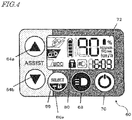
- FIG. 4 is an external view of the operation panel 60.
- the operation panel 60 includes a plurality of buttons 64a, 64b, 66, 68 and 70 and a liquid crystal panel 2.
- the plurality of buttons are, specifically, assist force setting buttons 64a and 64b, a switch button 66, a headlight button 68, and a power button 70.
- the assist force setting buttons 64a and 64b are usable to set an assist force of the electric motor 33 or a running mode corresponding to the magnitude of the assist force.
- the "assist force" of the electric motor 33 is a force assisting the human power.
- four running modes are set for the electrically power assisted bicycle 1.
- the four running modes are, for example, an assist-free mode, an ecological mode, a standard mode and a strong mode, in the order from the mode in which the magnitude of assist to the human power is weakest. In the assist-free mode, the electric motor 33 does not generate any assist force.
- the assist-free mode is changed to the ecological mode.
- the ecological mode is changed to the standard mode.
- the rider presses the assist force setting button 64a in the standard mode the standard mode is changed to the strong mode. Even if the rider presses the assist force setting button 64a in the strong mode, the strong mode is kept and is not changed any more.
- the assist force setting button 64b is pressed in this state, the strong mode is changed to the standard mode as described below.
- the assist force setting button 64b is pressed to select a running mode providing a weaker assist force, opposite to the assist force setting button 64a.
- the strong mode is changed to the standard mode.
- the standard mode is changed to the ecological mode.
- the ecological mode is changed to the assist-free mode. Even if the rider presses the assist force setting button 64b in the assist-free mode, the assist-free mode is kept and is not changed any more.
- the assist-free mode is changed to the ecological mode.
- a running mode display area is provided in a left area of the liquid crystal panel 72.
- the standard mode at the center is highlighted to show that the standard mode is now selected.
- the switch button 66 is usable by the rider to switch the display on the liquid crystal panel 72.
- the liquid crystal panel 72 is capable of displaying the remaining capacity of the battery 36, the remaining distance by which assisted running is possible, and the current running speed.
- the display on the liquid crystal panel 72 is sequentially switched to the remaining capacity of the battery 36, to the remaining distance by which assisted running is possible, and to the current running speed.
- such information is displayed in an upper right area of the liquid crystal panel 72.
- the remaining capacity of the battery 36 is displayed as "90%".
- the headlight button 68 is usable to switch on or off the headlight 2 alternately.
- the power button 70 is usable to turn on or off the driving system of the electrically power assisted bicycle 1.
- the driving system at least includes the electric motor 33, and the control device 32 or the control unit.
- the liquid crystal panel 72 displays letters, symbols, icons and the like by a segment system. This is merely illustrative.
- the liquid crystal panel 72 may display letters, symbols, icons and the like in a display area by a dot matrix system, or display a moving image.
- the liquid crystal panel 72 is an example.
- an organic EL, or electronic paper display panel or the like may be used.
- FIG. 5 shows a hardware structure of the operation panel 60.
- the operation panel 60 includes a microcontroller 62, an oscillator 74 formed of quartz or silicon, a ROM 76a, and a RAM 76b.
- the microcontroller 62 is a semiconductor integrated circuit controlling the operation of the operation panel 60.
- the microcomputer 62 is connected with the plurality of buttons 64a, 64b, 66, 68 and 70 to detect that the respective buttons have been pressed.
- the buttons may be pressed in the forms of "short press” and "long press”.
- the microcontroller 62 detects a "short press” and a "long press”. For example, when the rider starts pressing a button, the microcontroller 62 detects a voltage value and/or a current value of a predetermined level or higher. When the rider finishes pressing the button, the microcontroller 62 detects that the voltage value and/or the current value that has been detected is now, for example, zero.
- the microcontroller 62 determines whether the press was a short press or a long press based on the time period from the detection of the voltage value and/or the current value until the detection of the voltage value and/or the current value becoming zero.
- the microcontroller 62 may detect a short press or a long press of a plurality of buttons at the same time.
- the microcontroller 62 determines that the press is a "short press". By contrast, when the time period from when the rider starts pressing a button with his/her finger until releases the finger from the button is 3 seconds or longer, the microcontroller 62 determines that the press is a "long press”.
- the microcontroller 62 uses a counter 78. While a button is pressed, the microcontroller 62 counts up or counts down the value of the counter 78 by use of a clock signal supplied from the oscillator 74 or a frequency-divided signal obtained as a result of the frequency of the clock signal being divided. While, for example, being counted up, the count value is added in a cumulative manner in the counter 78. The count value directly corresponds to the time period in which the button is pressed (e.g., 1 second). The microcontroller 62 converts the count value into the length of the actual time period and executes the following process.
- the actual time period is expressed as C/f (sec.). The following description will be made with the length of the actual time period (unit: second) and the conversion computation will not be described in order to avoid a complicated explanation.
- a "short press” may be referred to as a "normal (first) operation".
- a reason for this is that an operation such as a short press is a usual operation that is made by a general rider with no specific attention.
- the rider may press the assist force setting button 64a or 64b once with his/her finger and instantaneously release the finger to change the running mode.
- the rider may press the headlight button 68 once with his/her finger and instantaneously release the finger to switch on or off the headlight 2.
- the time period with which it is considered that the rider "releases his/her finger from the button instantaneously” is set as described above.
- the microcontroller 62 determines whether or not the press is a short press. Since the short press is referred to as a normal operation, the long press is considered as an "operation that is not a normal operation". Another example of the "operation that is not a normal operation" is a repeated press operation.
- the microcontroller 62 may determine that an operation different from a short press, which is a normal operation, is made (i.e., that a repeated press operation is made) and perform the same process as made when a long press is made.
- the microcontroller 62 is provided to execute at least the process shown in the flowcharts described below and put a certain limitation such that the power button 70 would not be turned off by a normal operation.
- the microcontroller 62 reads the computer program stored on the ROM 76a and develops the program in the RAM 76b, so as to execute the process.
- the microcontroller 62 may receive the computer program via a communication device not shown.
- FIG. 6 shows a process procedure in this embodiment that is executable by the microcontroller 62 on a power lock operation by use of the operation panel 60.
- the "power lock operation” is an operation made in order to put the driving system into a state where the power thereof is not turned off by a short press on the power button 70 ("locked state"), or an operation made to cancel the locked state.
- the microcontroller 62 uses a "lock operation acceptance flag" to determine whether or not to accept the power lock operation.
- the lock operation acceptance flag is held in, for example, a register (not shown), which is a storage area in the microcontroller 62.
- the microcontroller 62 rewrites the lock operation acceptance flag to 1 or 0 at a predetermined timing.
- the lock operation acceptance flag in an example, when the lock operation acceptance flag is 1, the power lock operation is accepted, whereas when the lock operation acceptance flag is 0, the power lock operation is not accepted.
- the lock operation acceptance flag will be referred to simply as the "flag", hereinafter.
- step S1 the microcontroller 62 sets the flag to "0".
- step S2 the microcontroller 62 determines whether or not the switch button 66 is being pressed.
- the process procedure advances to step S3, whereas when the switch button 66 is not being pressed, the process procedure advances to step S4.
- step S1 a state immediately after the power button 70 of the electrically power assisted bicycle 1 in a power-off state is pressed to turn on the power thereof is assumed.
- step S4 the microcontroller 62 resets the counter 78.
- the microcontroller 62 sets the value of the counter 78 to "0".
- step S5 the microcontroller 62 sets the flag to 1 (step S5) and thus is put into a state where the power lock operation is acceptable.
- step S5 The microcontroller 62 executes the processes in steps S2, S4 and S5 periodically until the switch button 66 is pressed.
- the term "periodically” refers to, for example, once every several ten milliseconds.
- step S3 the microcontroller 62 determines whether or not the flag is 1.
- the process procedure advances to step S6, whereas when the flag is 0, the process procedure returns to step S2. Since step S3 is provided, the power lock operation is prohibited in the case where, for example, the switch button 62 is already pressed at the time when the power of the electrically power assisted bicycle 1 is turned on.
- step S6 the microcontroller 62 starts counting the cumulative long-press time period.
- the "cumulative long-press time period” refers to the time period in which the switch button 66 is kept pressed. During the cumulative long-press time period, the count value of the counter 78 keeps increasing in accordance with the supply of the clock signal from the oscillator 74.
- step S7 the microcontroller 62 determines whether or not the cumulative long-press time period is no less than 3 seconds. When the cumulative long-press time period is 3 seconds or longer, the process procedure advances to step S8, whereas when the cumulative long-press time period is shorter than 3 seconds, the process procedure returns to step S2.
- step S8 the microcontroller 62 determines whether or not the power lock operation is currently being made. When the power lock operation is not currently being made, the process procedure advances to step S9, whereas when the power lock operation is currently being made, the process procedure advances to step S10.
- step S9 the microcontroller 62 executes the power lock operation and displays, on the liquid crystal panel 72, a power lock icon 80 showing that the power lock operation is being made.
- the power lock icon 80 is shown in FIG. 4 .
- step S10 the microcontroller 62 cancels the locked state and dismisses the power lock icon 80 from the display panel 72.
- step S11 the microcontroller 62 sets the flag to 0 and executes the processes in step S2 and thereafter.
- the microcontroller 62 is operable in a switchable manner between an operation mode when the power is locked and an operation mode when the power is not locked.
- the operation mode when the power is not locked is referred to as a "normal operation mode”.
- the normal operation mode each time the power button 70 is pressed, the power is turned on and off alternately.
- the operation mode when the power is locked is referred to as a "power lock mode”.
- the power lock mode In the power lock mode, the power is prohibited from being turned off when a normal operation (short press) is made on the power button 70. Namely, the power-off operation by the power button 70 is locked.
- the rider may forget the current operation mode.
- the power is not turned off by a short press on the power button 70.
- the rider does not understand why the power is not turned off, and may be concerned that malfunction has occurred. Notifying the rider that the current operation mode is the power lock mode at an appropriate timing is useful for the rider.
- FIG. 7 shows a process procedure of, during the power lock mode, notifying the rider that the current operation mode is the power lock mode.
- step S21 the microcontroller 62 determines whether or not the power button 70 is pressed. Until the power button 70 is pressed, the process in step S21 is executed in repetition. When the power button 70 is pressed, the process procedure advances to step S22.
- step S22 the microcontroller 62 determines whether or not the power is in a locked state currently.
- the process procedure advances to step S23, whereas when the power is not in the locked state currently, the process procedure advances to step S24.
- step S23 the microcontroller 62 executes a blinking process on the power lock icon 80.
- the blinking process executed by the microcontroller 62 includes, for example, specifying an area or segment in the liquid crystal panel 72 where the power lock icon 80 is to be displayed, and applying a voltage to a liquid crystal layer periodically.
- the power lock icon 80 is displayed at a predefined position. Therefore, the area or segment to be specified may be prespecified at the time of production of the electrically power assisted bicycle 1.
- the power lock icon 80 is blinked, so that the rider is aware that the electrically power assisted bicycle 1 is currently in the power-locked state and is not turned off by a short press.
- step S21 After the power lock icon 80 is displayed in a blinking manner, the process procedure returns to step S21.
- step S24 the microcontroller 62 executes a power turning-off process.
- the power turning-off process includes, for example, a process of retracting the data used by the microcontroller 62, and a process of blocking the supply of the electric power to the driving system.
- the process procedure is finished.
- the power lock icon 80 is blinked when the power button 70 is pressed during the power lock mode, so that the rider understands that the power is currently locked and that a normal operation on the power button 70 is invalid.
- the power lock icon 80 is blinked on the liquid crystal panel 72.
- an LED indicator 66a may be provided so as to notify the rider that the power is currently locked.
- the LED indicator 66a is lit up when the power is locked, and may be blinked together with, or instead of, the power lock icon 80.
- a speaker may be provided in the operation panel 60 so as to output a notification audio signal. It is more preferable to output the notification audio signal while blinking the power lock icon 80. Only the notification audio signal may be output.
- the process of determining whether or not the switch button 66 is in an adhesion state is not indispensable according to the present teaching.
- a process not including the process of determining whether or not the switch button 66 is in an adhesion state will be described.
- FIG. 8 shows a modification of the process procedure on the power lock operation.
- the same steps as those in FIG. 6 bear the same step numbers. Except for step S31, the steps in FIG. 8 are the same as those in FIG. 6 , but the order thereof is different.
- the process procedure shown in FIG. 8 does not include the process on the flag.
- each of the steps will be described briefly.
- the process procedure shown in FIG. 8 is executed as one of interrupt process procedures executed when the microcontroller 62 receives an interrupt signal showing that the switch button 66 is pressed.
- the microcontroller 62 resets the counter 78 (step S4) and then determines whether or not the switch button 66 is being pressed (step S2).
- the microcontroller 62 starts counting the cumulative long-press time period (step S6). Until the cumulative long-press time period becomes 3 second or longer, the processes in steps S2 and S6 are repeated.
- the microcontroller 62 determines that the press on the switch button 66 is a short press and executes a display switch process (step S31).
- the "display switch process” is a process of switching the display to the remaining capacity of the battery, to the remaining distance by which assisted running is possible, and to the current running speed, as described above. The display switch process will not be described in detail.
- the microcontroller 62 executes the processes in step S8 and the process in step S9 or S10. As a result, the power lock operation is executed or the power-locked state is cancelled, and the power lock icon 80 is displayed or dismissed. Then, the interrupt process procedure shown in FIG. 8 is finished.
- the flowchart shown in each of FIG. 6 and FIG. 8 corresponds to both of the power lock execution process executed when the power is not locked (step S9) and the power unlock process executed when the power is locked (step S10).
- a reason for this is that it is reasonable that the computer program includes both of the processes.
- the flowchart shown in each of FIG. 6 and FIG. 8 is merely an example.
- a computer program of executing the power lock execution process when the power is not locked (step S9), and a computer program of executing the power unlock process when the power is locked (step S10) may be provided separately.
- Each of the processes described as a computer program is one of a plurality of embodiments according to the present teaching. In the case where such separate computer programs are provided, neither of such computer programs includes the determination process in step S8.
- the process corresponding to step S8 is executed when the microcontroller 62 determines which program is to be executed.
- the microcontroller 62 switches the operation mode to the normal operation mode or to the power lock mode when the switch button 66 is long-pressed. Since a button for switching the mode is not separately provided, the number of the buttons in the operation panel 60 is decreased. However, this is merely an example.
- the microcontroller 62 may switch the operation mode to the normal operation mode or to the power lock mode when a button different from the switch button 66 is long-pressed.
- the button different from the switch button 66 may be, for example, the assist force setting button 64a or 64b or the headlight button 68.
- a long press on the power button 70 may be used to switch the operation mode to the normal operation mode or to the power lock mode. In the normal operation made, the power is turned off when the power button 70 is short-pressed.
- buttons usable to switch the operation mode to the normal operation mode and a button usable to switch the operation mode to the power lock mode may be provided separately, or any button may be assigned as such a button. Namely, any button may be used by the microcontroller 62 to switch the operation mode to the normal operation mode or to the power lock mode when being long-pressed.
- the microcontroller 62 may turn off the power without returning the operation mode to the normal operation mode.
- buttons may be used as follows. For example, when the rider long-presses the power button 70 while pressing a button different from the power button 70 in a power-off state, the power is turned on and also the microcontroller 62 starts operating in the power lock mode. By contrast, when the rider long-presses the power button 70 while pressing a button different from the power button 70 in the power lock mode, the power lock mode is cancelled and the power is also turned off. Such a complicated operation is made requisite, so that the possibility that the power is turned off inadvertently is further decreased.
- the normal operation mode and the power lock mode are not distinguished from each other.
- the microcontroller 62 is permitted to turn off the power only when the power button 70 is long-pressed. Namely, a short press on the power button 70 does not turn off the power.
- the rider does not need to care whether the current operation mode is the normal operation mode or the power lock mode. Therefore, the operation is simplified, and the rider is not confused or less confused during the operation.
- the microcontroller 62 may light up the LED indicator 66a after the power is turned on. When detecting that the power button 70 is short-pressed, the microcontroller 62 may blink the power lock icon 80 as described above to notify the rider that the power is not turned off by a short press on the power button 70. The microcontroller 62 may blink the LED indicator 66a instead of the power lock icon 80. The microcontroller 62 may also output a notification audio signal from the speaker. It is more preferable to output the notification audio signal while blinking the power lock icon 80 or the LED indicator 66a. Only the notification audio signal may be output.
- the microcontroller 62 prohibits the power from being turned off by a short press on the power button 70, but may accept an operation made on any other button.
- the microcontroller 62 may accept an operation on the assist force setting button 64a or 64b to increase or decrease the assist force.
- the microcontroller 62 may prohibit the operation from being accepted. A reason for this is that when the assist force becomes completely zero, the rider needs to keep riding with only the human power, and the load on the rider increases. The operation to make the assist force zero is prohibited, so that the rider keeps on riding with an assist force.
- the microcontroller 62 may light up the headlight 2 in response to a normal operation on the headlight button 68.
- the rider is allowed to light up the headlight 2 without cancelling the power lock mode, which improves the convenience.
- the microcontroller 62 keeps the headlight 2 on. Namely, the microcontroller 62 prohibits the headlight 2 from being switched off in the power lock mode. Even when the headlight button 68 is pressed by, for example, a mischievous conduct of a child while the headlight button 68 is on, the headlight 2 is kept lit on. Therefore, the rider keeps on riding with a sufficient level of brightness.
- the present teaching is especially useful for an electrically power assisted bicycle including an operation panel and a plurality of (e.g., two or three) wheels.
Landscapes
- Engineering & Computer Science (AREA)
- Chemical & Material Sciences (AREA)
- Combustion & Propulsion (AREA)
- Mechanical Engineering (AREA)
- Transportation (AREA)
- Electric Propulsion And Braking For Vehicles (AREA)
Applications Claiming Priority (1)
| Application Number | Priority Date | Filing Date | Title |
|---|---|---|---|
| JP2016180401A JP6894206B2 (ja) | 2016-09-15 | 2016-09-15 | 電動補助車両 |
Publications (2)
| Publication Number | Publication Date |
|---|---|
| EP3296191A1 true EP3296191A1 (de) | 2018-03-21 |
| EP3296191B1 EP3296191B1 (de) | 2019-11-06 |
Family
ID=59887091
Family Applications (1)
| Application Number | Title | Priority Date | Filing Date |
|---|---|---|---|
| EP17191222.3A Active EP3296191B1 (de) | 2016-09-15 | 2017-09-15 | Fahrrad mit elektrischem hilfsmotor |
Country Status (4)
| Country | Link |
|---|---|
| US (1) | US10293882B2 (de) |
| EP (1) | EP3296191B1 (de) |
| JP (1) | JP6894206B2 (de) |
| CN (1) | CN107826204B (de) |
Cited By (1)
| Publication number | Priority date | Publication date | Assignee | Title |
|---|---|---|---|---|
| WO2022228915A1 (de) * | 2021-04-28 | 2022-11-03 | Robert Bosch Gmbh | Verfahren zum betreiben eines fahrrads |
Families Citing this family (17)
| Publication number | Priority date | Publication date | Assignee | Title |
|---|---|---|---|---|
| JP2017013524A (ja) * | 2015-06-26 | 2017-01-19 | ヤマハ発動機株式会社 | 電動補助自転車 |
| JP6720034B2 (ja) * | 2016-09-15 | 2020-07-08 | ヤマハ発動機株式会社 | 電動補助自転車 |
| DE102018202013A1 (de) * | 2017-02-10 | 2018-08-16 | Sram, Llc | Fahrrad-Kettenwerfer und -Verbindung |
| US10875601B2 (en) * | 2017-02-10 | 2020-12-29 | Sram, Llc | Bicycle derailleur and connection |
| JP6921783B2 (ja) * | 2018-05-25 | 2021-08-18 | 株式会社シマノ | 人力駆動車用制御装置 |
| US11597470B2 (en) | 2018-07-09 | 2023-03-07 | Shimano Inc. | Human-powered vehicle component, mobile electronic device, and equipment for human-powered vehicle |
| US11527981B2 (en) | 2018-07-09 | 2022-12-13 | Shimano Inc. | Human-powered vehicle control device, electronic device, and human-powered vehicle control system |
| US11731723B2 (en) * | 2018-07-09 | 2023-08-22 | Shimano Inc. | Rider recognition device for human-powered vehicle and control system of human-powered vehicle |
| US11527980B2 (en) | 2018-07-09 | 2022-12-13 | Shimano Inc. | Electronic device and human-powered vehicle system |
| US10703437B2 (en) * | 2018-08-21 | 2020-07-07 | Tien Industries Co., Ltd. | Electric power control assembly for bicycle electronic device and electric power control system having the same and control method thereof |
| TWI673202B (zh) * | 2018-11-16 | 2019-10-01 | Tektro Technology Corporation | 自行車元件的控制方法 |
| CN111377019A (zh) * | 2018-12-29 | 2020-07-07 | 北京骑胜科技有限公司 | 一种车辆控制设备 |
| CN111391953A (zh) * | 2018-12-29 | 2020-07-10 | 北京骑胜科技有限公司 | 一种电动车控制设备 |
| CN110139448A (zh) * | 2019-06-10 | 2019-08-16 | 佛山远钧智慧科技有限公司 | 一种节能减排智能化操控系统 |
| CN111422288A (zh) * | 2020-03-04 | 2020-07-17 | 广东酷米智能科技有限公司 | 一种新型电单车开关系统 |
| CN116062082B (zh) * | 2021-11-04 | 2025-09-23 | 南京懂玫驱动技术有限公司 | 电助力自行车的启动控制系统、方法 |
| CN119058872A (zh) * | 2023-06-01 | 2024-12-03 | 台达电子工业股份有限公司 | 电动辅助自行车的控制系统及控制方法 |
Citations (4)
| Publication number | Priority date | Publication date | Assignee | Title |
|---|---|---|---|---|
| JP2002362471A (ja) * | 2001-06-07 | 2002-12-18 | Sunstar Eng Inc | 操作スイッチを備えた電動アシスト自転車及び電動自転車 |
| JP2010155523A (ja) | 2008-12-26 | 2010-07-15 | Panasonic Corp | 電動アシスト車両用制御システム |
| US20150367750A1 (en) * | 2014-06-24 | 2015-12-24 | Shimano Inc. | Bicycle control apparatus |
| WO2017009637A1 (en) * | 2015-07-14 | 2017-01-19 | Grey Technology Limited | Electric cycle |
Family Cites Families (15)
| Publication number | Priority date | Publication date | Assignee | Title |
|---|---|---|---|---|
| JP2001099489A (ja) * | 1999-09-30 | 2001-04-13 | Sanyo Electric Co Ltd | 暖房機器 |
| JP2002329391A (ja) | 2001-04-26 | 2002-11-15 | Matsushita Electric Ind Co Ltd | 記録装置 |
| JP2003185152A (ja) | 2001-12-20 | 2003-07-03 | Sanyo Electric Co Ltd | 調理器 |
| JP2004142703A (ja) * | 2002-10-28 | 2004-05-20 | Matsushita Electric Ind Co Ltd | 電動補助自転車 |
| JP2007329810A (ja) | 2006-06-09 | 2007-12-20 | Sanyo Electric Co Ltd | 通信装置 |
| JP5343407B2 (ja) * | 2008-06-02 | 2013-11-13 | セイコーエプソン株式会社 | プロジェクタ |
| JP5143867B2 (ja) * | 2010-06-11 | 2013-02-13 | 株式会社シマノ | 自転車用の電装品制御システム |
| JP5205436B2 (ja) * | 2010-10-29 | 2013-06-05 | 株式会社シマノ | 自転車用モータ制御システム |
| JP5960649B2 (ja) * | 2013-06-12 | 2016-08-02 | ブリヂストンサイクル株式会社 | 電動機付自転車 |
| JP6220636B2 (ja) * | 2013-11-01 | 2017-10-25 | ヤマハ発動機株式会社 | 電動補助自転車 |
| JP6553440B2 (ja) * | 2015-07-29 | 2019-07-31 | 株式会社シマノ | 操作制御装置および自転車用表示装置 |
| JP6761314B2 (ja) * | 2016-09-15 | 2020-09-23 | ヤマハ発動機株式会社 | 電動補助自転車 |
| JP6929721B2 (ja) * | 2017-07-10 | 2021-09-01 | 株式会社シマノ | 自転車用制御装置、自転車用制御装置を含む電動補助ユニット、自転車用制御装置を含むサスペンション、および、自転車用制御装置を含むアジャスタブルシートポスト |
| US10377444B2 (en) * | 2017-07-31 | 2019-08-13 | Shimano Inc. | Bicycle electric component |
| JP6914594B2 (ja) * | 2017-08-09 | 2021-08-04 | ヤマハ発動機株式会社 | 駆動ユニットおよび電動補助自転車 |
-
2016
- 2016-09-15 JP JP2016180401A patent/JP6894206B2/ja active Active
-
2017
- 2017-09-14 US US15/704,107 patent/US10293882B2/en active Active
- 2017-09-14 CN CN201710827557.6A patent/CN107826204B/zh active Active
- 2017-09-15 EP EP17191222.3A patent/EP3296191B1/de active Active
Patent Citations (4)
| Publication number | Priority date | Publication date | Assignee | Title |
|---|---|---|---|---|
| JP2002362471A (ja) * | 2001-06-07 | 2002-12-18 | Sunstar Eng Inc | 操作スイッチを備えた電動アシスト自転車及び電動自転車 |
| JP2010155523A (ja) | 2008-12-26 | 2010-07-15 | Panasonic Corp | 電動アシスト車両用制御システム |
| US20150367750A1 (en) * | 2014-06-24 | 2015-12-24 | Shimano Inc. | Bicycle control apparatus |
| WO2017009637A1 (en) * | 2015-07-14 | 2017-01-19 | Grey Technology Limited | Electric cycle |
Non-Patent Citations (1)
| Title |
|---|
| SUZHOU KUNTENG ELECTRONICS CO LTD.: "User handbook for KT_LCD exclusive apparatus of electric-aided bicycle", 10 May 2011 (2011-05-10), XP055449009, Retrieved from the Internet <URL:http://wooshbikes.co.uk/manuals/Sport-TS_LCD_settings.pdf> [retrieved on 20180207] * |
Cited By (1)
| Publication number | Priority date | Publication date | Assignee | Title |
|---|---|---|---|---|
| WO2022228915A1 (de) * | 2021-04-28 | 2022-11-03 | Robert Bosch Gmbh | Verfahren zum betreiben eines fahrrads |
Also Published As
| Publication number | Publication date |
|---|---|
| CN107826204B (zh) | 2020-07-03 |
| US20180072373A1 (en) | 2018-03-15 |
| JP2018043663A (ja) | 2018-03-22 |
| JP6894206B2 (ja) | 2021-06-30 |
| US10293882B2 (en) | 2019-05-21 |
| EP3296191B1 (de) | 2019-11-06 |
| CN107826204A (zh) | 2018-03-23 |
Similar Documents
| Publication | Publication Date | Title |
|---|---|---|
| EP3296191B1 (de) | Fahrrad mit elektrischem hilfsmotor | |
| EP3296187B1 (de) | Fahrrad mit elektrischem hilfsantrieb und verfahren zur ansteuerung eines fahrrads mit elektrischem hilfsantrieb | |
| US10479440B2 (en) | Electrically power assisted bicycle | |
| JP5986150B2 (ja) | 自転車用制御装置、自転車用制御装置を備える電動アシスト自転車、及び電動アシスト自転車のモータ制御方法 | |
| CN110114265B (zh) | 电动辅助系统和电动辅助车辆 | |
| JP5566975B2 (ja) | 自転車用制御装置 | |
| JP6903754B2 (ja) | 電動補助自転車 | |
| JP6325596B2 (ja) | 自転車用制御装置、及び自転車用制御装置を備える電動アシスト自転車 | |
| JP2019081397A (ja) | 人力駆動車両用制御装置 | |
| JP6479553B2 (ja) | 電動補助自転車 | |
| JP6193931B2 (ja) | 自転車用制御装置 | |
| JP2023056725A (ja) | 報知システムおよび電動補助車両 | |
| CN219192461U (zh) | 一种车辆接触检测控制系统 | |
| JP7643989B2 (ja) | 制御システム、および、人力駆動車用制御装置 | |
| JP7737342B2 (ja) | 人力駆動車用の制御システム | |
| JP7186126B2 (ja) | 人力駆動車用制御装置、人力駆動車用ドライブユニット、人力駆動車用制御方法、および、外部端末 | |
| US12485994B2 (en) | Electrically assisted bicycle | |
| CN115892317A (zh) | 一种车辆接触检测控制系统 | |
| JP2003348711A (ja) | 電動式鞍乗型車両における非乗車時の走行規制装置 | |
| JP2019043343A (ja) | 電動自転車 |
Legal Events
| Date | Code | Title | Description |
|---|---|---|---|
| PUAI | Public reference made under article 153(3) epc to a published international application that has entered the european phase |
Free format text: ORIGINAL CODE: 0009012 |
|
| STAA | Information on the status of an ep patent application or granted ep patent |
Free format text: STATUS: THE APPLICATION HAS BEEN PUBLISHED |
|
| AK | Designated contracting states |
Kind code of ref document: A1 Designated state(s): AL AT BE BG CH CY CZ DE DK EE ES FI FR GB GR HR HU IE IS IT LI LT LU LV MC MK MT NL NO PL PT RO RS SE SI SK SM TR |
|
| AX | Request for extension of the european patent |
Extension state: BA ME |
|
| STAA | Information on the status of an ep patent application or granted ep patent |
Free format text: STATUS: REQUEST FOR EXAMINATION WAS MADE |
|
| 17P | Request for examination filed |
Effective date: 20180921 |
|
| RBV | Designated contracting states (corrected) |
Designated state(s): AL AT BE BG CH CY CZ DE DK EE ES FI FR GB GR HR HU IE IS IT LI LT LU LV MC MK MT NL NO PL PT RO RS SE SI SK SM TR |
|
| STAA | Information on the status of an ep patent application or granted ep patent |
Free format text: STATUS: EXAMINATION IS IN PROGRESS |
|
| 17Q | First examination report despatched |
Effective date: 20181106 |
|
| RIC1 | Information provided on ipc code assigned before grant |
Ipc: B62J 99/00 20090101ALN20190425BHEP Ipc: B62M 6/80 20100101ALN20190425BHEP Ipc: B62M 6/45 20100101AFI20190425BHEP |
|
| RIC1 | Information provided on ipc code assigned before grant |
Ipc: B62J 99/00 20090101ALN20190507BHEP Ipc: B62M 6/80 20100101ALN20190507BHEP Ipc: B62M 6/45 20100101AFI20190507BHEP |
|
| GRAP | Despatch of communication of intention to grant a patent |
Free format text: ORIGINAL CODE: EPIDOSNIGR1 |
|
| STAA | Information on the status of an ep patent application or granted ep patent |
Free format text: STATUS: GRANT OF PATENT IS INTENDED |
|
| RIC1 | Information provided on ipc code assigned before grant |
Ipc: B62M 6/80 20100101ALN20190524BHEP Ipc: B62M 6/45 20100101AFI20190524BHEP Ipc: B62J 99/00 20090101ALN20190524BHEP |
|
| INTG | Intention to grant announced |
Effective date: 20190628 |
|
| GRAS | Grant fee paid |
Free format text: ORIGINAL CODE: EPIDOSNIGR3 |
|
| GRAA | (expected) grant |
Free format text: ORIGINAL CODE: 0009210 |
|
| STAA | Information on the status of an ep patent application or granted ep patent |
Free format text: STATUS: THE PATENT HAS BEEN GRANTED |
|
| AK | Designated contracting states |
Kind code of ref document: B1 Designated state(s): AL AT BE BG CH CY CZ DE DK EE ES FI FR GB GR HR HU IE IS IT LI LT LU LV MC MK MT NL NO PL PT RO RS SE SI SK SM TR |
|
| REG | Reference to a national code |
Ref country code: GB Ref legal event code: FG4D |
|
| REG | Reference to a national code |
Ref country code: CH Ref legal event code: EP Ref country code: AT Ref legal event code: REF Ref document number: 1198393 Country of ref document: AT Kind code of ref document: T Effective date: 20191115 |
|
| REG | Reference to a national code |
Ref country code: IE Ref legal event code: FG4D |
|
| REG | Reference to a national code |
Ref country code: DE Ref legal event code: R096 Ref document number: 602017008398 Country of ref document: DE |
|
| REG | Reference to a national code |
Ref country code: NL Ref legal event code: MP Effective date: 20191106 |
|
| REG | Reference to a national code |
Ref country code: LT Ref legal event code: MG4D |
|
| PG25 | Lapsed in a contracting state [announced via postgrant information from national office to epo] |
Ref country code: PL Free format text: LAPSE BECAUSE OF FAILURE TO SUBMIT A TRANSLATION OF THE DESCRIPTION OR TO PAY THE FEE WITHIN THE PRESCRIBED TIME-LIMIT Effective date: 20191106 Ref country code: LT Free format text: LAPSE BECAUSE OF FAILURE TO SUBMIT A TRANSLATION OF THE DESCRIPTION OR TO PAY THE FEE WITHIN THE PRESCRIBED TIME-LIMIT Effective date: 20191106 Ref country code: NL Free format text: LAPSE BECAUSE OF FAILURE TO SUBMIT A TRANSLATION OF THE DESCRIPTION OR TO PAY THE FEE WITHIN THE PRESCRIBED TIME-LIMIT Effective date: 20191106 Ref country code: LV Free format text: LAPSE BECAUSE OF FAILURE TO SUBMIT A TRANSLATION OF THE DESCRIPTION OR TO PAY THE FEE WITHIN THE PRESCRIBED TIME-LIMIT Effective date: 20191106 Ref country code: SE Free format text: LAPSE BECAUSE OF FAILURE TO SUBMIT A TRANSLATION OF THE DESCRIPTION OR TO PAY THE FEE WITHIN THE PRESCRIBED TIME-LIMIT Effective date: 20191106 Ref country code: NO Free format text: LAPSE BECAUSE OF FAILURE TO SUBMIT A TRANSLATION OF THE DESCRIPTION OR TO PAY THE FEE WITHIN THE PRESCRIBED TIME-LIMIT Effective date: 20200206 Ref country code: GR Free format text: LAPSE BECAUSE OF FAILURE TO SUBMIT A TRANSLATION OF THE DESCRIPTION OR TO PAY THE FEE WITHIN THE PRESCRIBED TIME-LIMIT Effective date: 20200207 Ref country code: PT Free format text: LAPSE BECAUSE OF FAILURE TO SUBMIT A TRANSLATION OF THE DESCRIPTION OR TO PAY THE FEE WITHIN THE PRESCRIBED TIME-LIMIT Effective date: 20200306 Ref country code: FI Free format text: LAPSE BECAUSE OF FAILURE TO SUBMIT A TRANSLATION OF THE DESCRIPTION OR TO PAY THE FEE WITHIN THE PRESCRIBED TIME-LIMIT Effective date: 20191106 Ref country code: BG Free format text: LAPSE BECAUSE OF FAILURE TO SUBMIT A TRANSLATION OF THE DESCRIPTION OR TO PAY THE FEE WITHIN THE PRESCRIBED TIME-LIMIT Effective date: 20200206 |
|
| PG25 | Lapsed in a contracting state [announced via postgrant information from national office to epo] |
Ref country code: RS Free format text: LAPSE BECAUSE OF FAILURE TO SUBMIT A TRANSLATION OF THE DESCRIPTION OR TO PAY THE FEE WITHIN THE PRESCRIBED TIME-LIMIT Effective date: 20191106 Ref country code: HR Free format text: LAPSE BECAUSE OF FAILURE TO SUBMIT A TRANSLATION OF THE DESCRIPTION OR TO PAY THE FEE WITHIN THE PRESCRIBED TIME-LIMIT Effective date: 20191106 Ref country code: IS Free format text: LAPSE BECAUSE OF FAILURE TO SUBMIT A TRANSLATION OF THE DESCRIPTION OR TO PAY THE FEE WITHIN THE PRESCRIBED TIME-LIMIT Effective date: 20200306 |
|
| PG25 | Lapsed in a contracting state [announced via postgrant information from national office to epo] |
Ref country code: AL Free format text: LAPSE BECAUSE OF FAILURE TO SUBMIT A TRANSLATION OF THE DESCRIPTION OR TO PAY THE FEE WITHIN THE PRESCRIBED TIME-LIMIT Effective date: 20191106 |
|
| PG25 | Lapsed in a contracting state [announced via postgrant information from national office to epo] |
Ref country code: DK Free format text: LAPSE BECAUSE OF FAILURE TO SUBMIT A TRANSLATION OF THE DESCRIPTION OR TO PAY THE FEE WITHIN THE PRESCRIBED TIME-LIMIT Effective date: 20191106 Ref country code: EE Free format text: LAPSE BECAUSE OF FAILURE TO SUBMIT A TRANSLATION OF THE DESCRIPTION OR TO PAY THE FEE WITHIN THE PRESCRIBED TIME-LIMIT Effective date: 20191106 Ref country code: RO Free format text: LAPSE BECAUSE OF FAILURE TO SUBMIT A TRANSLATION OF THE DESCRIPTION OR TO PAY THE FEE WITHIN THE PRESCRIBED TIME-LIMIT Effective date: 20191106 Ref country code: ES Free format text: LAPSE BECAUSE OF FAILURE TO SUBMIT A TRANSLATION OF THE DESCRIPTION OR TO PAY THE FEE WITHIN THE PRESCRIBED TIME-LIMIT Effective date: 20191106 Ref country code: CZ Free format text: LAPSE BECAUSE OF FAILURE TO SUBMIT A TRANSLATION OF THE DESCRIPTION OR TO PAY THE FEE WITHIN THE PRESCRIBED TIME-LIMIT Effective date: 20191106 |
|
| REG | Reference to a national code |
Ref country code: DE Ref legal event code: R097 Ref document number: 602017008398 Country of ref document: DE |
|
| REG | Reference to a national code |
Ref country code: AT Ref legal event code: MK05 Ref document number: 1198393 Country of ref document: AT Kind code of ref document: T Effective date: 20191106 |
|
| PG25 | Lapsed in a contracting state [announced via postgrant information from national office to epo] |
Ref country code: SK Free format text: LAPSE BECAUSE OF FAILURE TO SUBMIT A TRANSLATION OF THE DESCRIPTION OR TO PAY THE FEE WITHIN THE PRESCRIBED TIME-LIMIT Effective date: 20191106 Ref country code: SM Free format text: LAPSE BECAUSE OF FAILURE TO SUBMIT A TRANSLATION OF THE DESCRIPTION OR TO PAY THE FEE WITHIN THE PRESCRIBED TIME-LIMIT Effective date: 20191106 |
|
| PLBE | No opposition filed within time limit |
Free format text: ORIGINAL CODE: 0009261 |
|
| STAA | Information on the status of an ep patent application or granted ep patent |
Free format text: STATUS: NO OPPOSITION FILED WITHIN TIME LIMIT |
|
| 26N | No opposition filed |
Effective date: 20200807 |
|
| PG25 | Lapsed in a contracting state [announced via postgrant information from national office to epo] |
Ref country code: AT Free format text: LAPSE BECAUSE OF FAILURE TO SUBMIT A TRANSLATION OF THE DESCRIPTION OR TO PAY THE FEE WITHIN THE PRESCRIBED TIME-LIMIT Effective date: 20191106 Ref country code: SI Free format text: LAPSE BECAUSE OF FAILURE TO SUBMIT A TRANSLATION OF THE DESCRIPTION OR TO PAY THE FEE WITHIN THE PRESCRIBED TIME-LIMIT Effective date: 20191106 |
|
| PG25 | Lapsed in a contracting state [announced via postgrant information from national office to epo] |
Ref country code: IT Free format text: LAPSE BECAUSE OF FAILURE TO SUBMIT A TRANSLATION OF THE DESCRIPTION OR TO PAY THE FEE WITHIN THE PRESCRIBED TIME-LIMIT Effective date: 20191106 |
|
| REG | Reference to a national code |
Ref country code: CH Ref legal event code: PL |
|
| REG | Reference to a national code |
Ref country code: BE Ref legal event code: MM Effective date: 20200930 |
|
| PG25 | Lapsed in a contracting state [announced via postgrant information from national office to epo] |
Ref country code: LU Free format text: LAPSE BECAUSE OF NON-PAYMENT OF DUE FEES Effective date: 20200915 |
|
| PG25 | Lapsed in a contracting state [announced via postgrant information from national office to epo] |
Ref country code: FR Free format text: LAPSE BECAUSE OF NON-PAYMENT OF DUE FEES Effective date: 20200930 |
|
| PG25 | Lapsed in a contracting state [announced via postgrant information from national office to epo] |
Ref country code: BE Free format text: LAPSE BECAUSE OF NON-PAYMENT OF DUE FEES Effective date: 20200930 Ref country code: CH Free format text: LAPSE BECAUSE OF NON-PAYMENT OF DUE FEES Effective date: 20200930 Ref country code: IE Free format text: LAPSE BECAUSE OF NON-PAYMENT OF DUE FEES Effective date: 20200915 Ref country code: LI Free format text: LAPSE BECAUSE OF NON-PAYMENT OF DUE FEES Effective date: 20200930 |
|
| GBPC | Gb: european patent ceased through non-payment of renewal fee |
Effective date: 20210915 |
|
| PG25 | Lapsed in a contracting state [announced via postgrant information from national office to epo] |
Ref country code: TR Free format text: LAPSE BECAUSE OF FAILURE TO SUBMIT A TRANSLATION OF THE DESCRIPTION OR TO PAY THE FEE WITHIN THE PRESCRIBED TIME-LIMIT Effective date: 20191106 Ref country code: MT Free format text: LAPSE BECAUSE OF FAILURE TO SUBMIT A TRANSLATION OF THE DESCRIPTION OR TO PAY THE FEE WITHIN THE PRESCRIBED TIME-LIMIT Effective date: 20191106 Ref country code: CY Free format text: LAPSE BECAUSE OF FAILURE TO SUBMIT A TRANSLATION OF THE DESCRIPTION OR TO PAY THE FEE WITHIN THE PRESCRIBED TIME-LIMIT Effective date: 20191106 |
|
| PG25 | Lapsed in a contracting state [announced via postgrant information from national office to epo] |
Ref country code: MK Free format text: LAPSE BECAUSE OF FAILURE TO SUBMIT A TRANSLATION OF THE DESCRIPTION OR TO PAY THE FEE WITHIN THE PRESCRIBED TIME-LIMIT Effective date: 20191106 Ref country code: MC Free format text: LAPSE BECAUSE OF FAILURE TO SUBMIT A TRANSLATION OF THE DESCRIPTION OR TO PAY THE FEE WITHIN THE PRESCRIBED TIME-LIMIT Effective date: 20191106 |
|
| PG25 | Lapsed in a contracting state [announced via postgrant information from national office to epo] |
Ref country code: GB Free format text: LAPSE BECAUSE OF NON-PAYMENT OF DUE FEES Effective date: 20210915 |
|
| PGFP | Annual fee paid to national office [announced via postgrant information from national office to epo] |
Ref country code: DE Payment date: 20250919 Year of fee payment: 9 |