EP3294470B1 - Procédé de fabrication d'une bande métallique au cours d'un procédé de laminage de coulée continue - Google Patents
Procédé de fabrication d'une bande métallique au cours d'un procédé de laminage de coulée continue Download PDFInfo
- Publication number
- EP3294470B1 EP3294470B1 EP16721446.9A EP16721446A EP3294470B1 EP 3294470 B1 EP3294470 B1 EP 3294470B1 EP 16721446 A EP16721446 A EP 16721446A EP 3294470 B1 EP3294470 B1 EP 3294470B1
- Authority
- EP
- European Patent Office
- Prior art keywords
- strip
- separating device
- induction heating
- rolling
- heating means
- Prior art date
- Legal status (The legal status is an assumption and is not a legal conclusion. Google has not performed a legal analysis and makes no representation as to the accuracy of the status listed.)
- Active
Links
Images


Classifications
-
- B—PERFORMING OPERATIONS; TRANSPORTING
- B21—MECHANICAL METAL-WORKING WITHOUT ESSENTIALLY REMOVING MATERIAL; PUNCHING METAL
- B21B—ROLLING OF METAL
- B21B1/00—Metal-rolling methods or mills for making semi-finished products of solid or profiled cross-section; Sequence of operations in milling trains; Layout of rolling-mill plant, e.g. grouping of stands; Succession of passes or of sectional pass alternations
- B21B1/46—Metal-rolling methods or mills for making semi-finished products of solid or profiled cross-section; Sequence of operations in milling trains; Layout of rolling-mill plant, e.g. grouping of stands; Succession of passes or of sectional pass alternations for rolling metal immediately subsequent to continuous casting
- B21B1/463—Metal-rolling methods or mills for making semi-finished products of solid or profiled cross-section; Sequence of operations in milling trains; Layout of rolling-mill plant, e.g. grouping of stands; Succession of passes or of sectional pass alternations for rolling metal immediately subsequent to continuous casting in a continuous process, i.e. the cast not being cut before rolling
-
- B—PERFORMING OPERATIONS; TRANSPORTING
- B21—MECHANICAL METAL-WORKING WITHOUT ESSENTIALLY REMOVING MATERIAL; PUNCHING METAL
- B21B—ROLLING OF METAL
- B21B15/00—Arrangements for performing additional metal-working operations specially combined with or arranged in, or specially adapted for use in connection with, metal-rolling mills
- B21B15/0007—Cutting or shearing the product
- B21B2015/0014—Cutting or shearing the product transversely to the rolling direction
-
- B—PERFORMING OPERATIONS; TRANSPORTING
- B21—MECHANICAL METAL-WORKING WITHOUT ESSENTIALLY REMOVING MATERIAL; PUNCHING METAL
- B21B—ROLLING OF METAL
- B21B37/00—Control devices or methods specially adapted for metal-rolling mills or the work produced thereby
- B21B37/74—Temperature control, e.g. by cooling or heating the rolls or the product
-
- B—PERFORMING OPERATIONS; TRANSPORTING
- B21—MECHANICAL METAL-WORKING WITHOUT ESSENTIALLY REMOVING MATERIAL; PUNCHING METAL
- B21B—ROLLING OF METAL
- B21B45/00—Devices for surface or other treatment of work, specially combined with or arranged in, or specially adapted for use in connection with, metal-rolling mills
- B21B45/004—Heating the product
Definitions
- the invention relates to a method for producing a metallic strip in the continuous casting rolling process, in which first a slab is poured in a casting machine and fed in the conveying direction of the belt downstream rolling mill stands and rolled here.
- the present invention is accordingly used in cast-rolling plants which produce a finished strip from liquid metal in continuous operation.
- a strategy is proposed which can be used if an interruption of the rolling operation in rolling mills of the rolling mill occurs intentionally or unintentionally.
- Known casting mills convert liquid steel in a compact plant to hot strip.
- slabs of endless length are poured. These slabs are cut by means of scissors which correspond in size to a desired hot-rolled size.
- furnaces often designed as a roller hearth furnace, the slabs are conditioned in temperature. Subsequently, the slabs are individually fed to a rolling train and rolled. Subsequently, the strips are cooled in a cooling section and reeled. The leagues leave the rolling line for further processing.
- the slabs are cut so that two or more bundles can be produced from this slab.
- flying scissors are additionally arranged, which cuts the long hot strip, so that the desired waist size is achieved.
- Both process forms have in common that can take place decoupled by the separation, in particular cutting the slab, the casting process and the rolling process.
- the possible and necessary process speeds of casting machine and rolling train are thus independently adjustable.
- Disturbances can basically occur in all subareas, ie. H. in the area of the reel, the flying shear (s), the finishing train, the roller hearth furnace, etc.
- a Verwalzer in the finishing mill z. B. torn ligament between the last two scaffolding so within a very short time leads to a jam between these scaffolding, which can only be eliminated by manual activities. This requires time-consuming work with subsequent inspection and, if necessary, repair of the plant components.
- the helmsman or the automation system stops rolling in the event of a fault.
- the scaffolds are generally driven in the shortest possible time, all drives are stopped and the strand comes to a standstill. Since the slab is not divided up to the mold, there are cases where inevitably the casting machine comes to a standstill. This unit is particularly critical to see. If the shutdown takes too long, the steel solidifies in the mold and can only be removed with great effort.
- WO 2015/101577 A1 are a method and apparatus for producing a metallic strip in the continuous casting roll method in which first a slab cast in a casting machine and fed to a downstream in the conveying direction of the strip finishing mill and rolled here. If a production interruption occurs in the finished rolling mill should, the band is cut at a location between the casting machine and the finish rolling mill by means of a separating device, wherein the part of the strip following the cut, is conveyed in a band memory by means of a driver, which is arranged in the conveying direction behind the separating device , Subsequently, the band is again cut through the separator, and chopped into individual parts. Finally, the tape section stored in the tape store is also shredded by the separating device by feeding this tape section opposite to the conveying direction of the tape to the separating device.
- the operation should not be interrupted as much as possible even during a planned roll change.
- the strand is separated, the severed band is rolled out. Subsequently, slices are cut from the strand and transported away by means of a discharge device as scrap.
- the scrapers possibly stacked behind the scissors can not necessarily be returned directly into the oven.
- the scrap must then rather be divided in an intermediate step.
- the scissors can not chop backwards. Furthermore, no scrap chute is present.
- WO 2009/121678 A1 shows a method and an apparatus for producing hot-rolled products in a cast-rolling composite plant, wherein the uninterrupted continuous casting process can be maintained even in an unplanned production interruption.
- the following process or sub-steps are carried out: a) cutting a strand section of a continuously produced starting material by means of a first pair of scissors; b) lifting the foot part of the strand section from the roller table by means of a lifting device; c) Dismembering the primary material passing through the first shears into scrap pieces by means of the first shears, discharging the scrap pieces, removing the strand section, and restoring the operational readiness of the cast-rolling composite plant.
- EP 0 625 383 B1 and EP 2 428 288 B1 each show a process for the production of a metallic strip in the cast rolling process, according to the preamble of claim 1.
- the invention has for its object to ensure an improved strip quality in a G manwalzbacter.
- the invention is achieved by a method for producing a metal strip in the casting-rolling process, in which the strip is cast in a casting machine and then rolled in stands which are downstream of the casting machine in the conveying direction of the strip.
- at least one first separating device is arranged upstream of at least one first rolling mill stand.
- An induction heater is disposed upstream of the first separator such that the heater coil is brought into interaction with the induction heater for heating.
- a part of the strip which has a deviation from a temperature-based setpoint value is separated from the respective subsequent strip by means of the first separating device.
- Separating a portion of the belt having temperatures deviating from a desired value causes that part to be removed from the production line and thus excluded from further rolling downstream of the induction heating.
- the remaining portion of the belt that meets the specifications for a desired temperature may then be rolled with predetermined rolling parameters in the mill train downstream of the first separator, with uniform material properties.
- the induction heating is then arranged between the first separation device and the second separation device.
- a part of the strip which has a deviation from a geometrical desired value is separated from the respective subsequent strip by means of the second separating device, and then removed from the production line. This ensures that components of the production line downstream of the second separating device, in particular the induction heating, are not damaged by such parts of the belt with deviating or faulty geometry.
- first separating device and the second separating device are arranged between the first and second rolling stands, which cut through the strip in the region between the first and second rolling stand, wherein the band is divided into an intermediate portion, a downstream portion and an upstream portion. It is expedient if the first and second separating device are actuated simultaneously.
- the intermediate portion of the band is between the first and second separators.
- the downstream section is that part of the belt that is downstream of the first separator.
- the upstream section is that part of the belt that is upstream of the second separator.
- the invention is based on the essential finding that it is possible in the event of a malfunction or interruption of production in the rolling mill, with a cutting of the tape by means of the separating devices and a subsequent chop-cutting of the respective sections of the strip, or a cutting of the respective sections of the strip into parts with a predetermined length in connection with stacking these band parts, a "jam" of the band within the rolling mill, and thus to prevent damage to rolling stands and other components of the production line.
- this makes it possible to minimize or even avoid downtimes within the production line.
- it is possible by the present invention in the event of malfunction or interruption occurring in the rolling mill to minimize band losses, and - after elimination of the disturbance - to get back to the normal continuous operation in a short time.
- the actuations of the separating means can be carried out by means of a control device. This means that by means of the control device, an operation of the separating devices is ensured.
- control device it is possible with the aid of the control device to carry out the inventive method fully automatically, for example, until the intermediate portion of the tape has been completely removed from the area between the first and second separator, and the disturbance in the rolling mill has been resolved.
- the invention may be integrated in the rolling mill sensor devices by means of which a fault is detected in the rolling operation.
- an operation, in particular the second separating device by means of the control device is carried out fully automatically, or can be confirmed individually by the operator.
- the method according to the present invention can be controlled in such a way that extensive algorithms for different incidents in the system control or the aforementioned control device are stored.
- a straightening device for example in the form of a straightening unit or an insertion funnel, be arranged. Before the belt enters the induction heating, this straightening device is brought into contact with the belt, so that the belt rests as flat as possible on the roller table.
- a straightening device is particularly recommended for the case when a front end of the band has a geometric deviation in the manner of a "ski".
- the induction heating can be designed for a so-called "boost mode", i. for operation with a short-term overload.
- boost mode i. for operation with a short-term overload.
- Such an operation of induction heating can more intensively heat the strip, and in particular the front end thereof, when a new strip is rolled out, effectively counteracting a transmission loss resulting from a possibly greater distance of the induction heating from the strip.
- induction coils with higher power for the induction heating, and / or to use additional induction coils in the induction heating.
- additional induction coils in the induction heating.
- Fig. 1 shows a side view of a part of a casting-rolling plant, with which a strip 1 is rolled in a production line 2.
- This production line 2 is provided following a casting machine, wherein such a casting machine belongs to the prior art and is therefore not shown in the drawing.
- the main components of production line 2 are explained below: Scaffolds are provided, namely a first rolling stand 10 and, downstream thereof, a second rolling stand 11. Between these rolling stands 10, 11 a first separating device 12 and a second separating device 13 are arranged. In this case, the second separating device 3 is located upstream of the first separating device 12 in the conveying direction F of the strip 1.
- the production line 2 is equipped with a control device 17, with which the essential components of the production line 2 can be suitably controlled.
- the control device 17 is in the Fig. 1 only symbolically indicated, with signal lines or the like between the controller 17 and the other components of the production line 2 are not shown for simplicity.
- driver devices 18, 19 are provided, by means of which the belt 1 can be transported or conveyed on a roller table 4 of the production line 2.
- a scale scrubber 22 is integrated into the production line 2.
- first rolling stand 10 may be part of a roughing mill 6, wherein the second rolling stand 11 may be part of a finishing mill 8.
- second rolling stand 11 is arranged downstream of the first rolling stand 10, wherein the first and second separating means 12, 13 are provided in a region between the first rolling stand 10 and the second rolling stand 11.
- a method according to the present invention may be used in a production line 2 according to Fig. 1 or. Fig. 2 and works as follows: If a disturbance or stoppage of production occurs within the production line 2, or in rolling mills (not shown) or other components of the rolling line downstream thereof, the above-described steps (a) to (d) are performed. Specifically, in step (a), the two separators 12, 13 are preferably operated simultaneously to cut the tape 1 at these locations.
- step (b) the downstream section I of the belt 1 is conveyed away from the first separator 12, namely in the conveying direction F, preferably by an actuation of the driving device 19 arranged downstream of the first separating device 12 Separator 12 "released" from the downstream section I, and then can be operated again.
- the intermediate portion Z of the belt 1, in step (c) is conveyed by the driving means 18 toward the first separator 12, and then cut by means of the first separator 12.
- the intermediate portion Z of the belt 1 can be shredded, in which case the chopped parts of the intermediate portion Z fall down into a receiving device 16 in the form of a scrap container, which is inserted into the provided below the first separator 12 collecting space 14 is.
- the upstream section II can also be shredded, the band chaff falling down into a receiving device 16 which is inserted into the space provided below the second separator 13 collecting space 14.
- scrap containers 16 which are introduced into the respective collecting chambers 14 for receiving the chopped strip sections, it is understood that these scrap containers 16, after complete filling, can be replaced.
- an induction heater 20 is arranged in the area between the first separator 12 and the second separator 13.
- the band 1 can be specifically heated within the production line 2.
- the induction heater 20 may be formed divided: As shown schematically simplified front view of Fig. 3 are then above the belt 1, an upper induction coil 20.1 and below the belt 1, a lower induction coil 20.2 arranged. As indicated by the double arrows in Fig. 3 indicated, a distance of the induction coils 20.1, 20.2 (either individually, or synchronously with each other) can be changed to the band 1 to set a resulting height H of the induction coils 20.1, 20.2 with respect to the belt 1.
- the electrical connections for the induction heater 20 are in the Fig. 3 simplified by "21" indicated.
- the induction heater 20 may also be integrally formed, as schematically simplified in the end view of Fig. 4 illustrated.
- the electrical connections for the induction heater 20 are simplified by the reference numeral "21" indicated.
- rolling of the strip 1 in the production line 2 can be optimized by a portion of the belt 1 having a temperature deviating from a predetermined target value is cut out by the first separator 12. This has the consequence that such a type cut out part of the strip 1 in the rolling stands downstream of the first separator 12 is no longer rolled, but instead falls into the plenum below the first separator 12. This ensures that, downstream of the first separating device 12, the following part of the strip 1 is rolled exclusively at a predetermined temperature, which leads to an increased product quality.
- a part of the belt 1, which has a deviation from a geometrical desired value is separated by means of the second separating device 13 from the respectively subsequent belt 1.
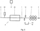
- Fig. 5 shows - schematically simplified - a side view of a part of a production line 2, with which the inventive method can be carried out according to a further embodiment.
- Fig. 5 are compared to the representation of Fig. 2 identical components provided with the same reference numerals, and therefore not explained again in detail.
- At least one first separating device 12 is provided, which is arranged upstream of a rolling stand 11 and which is viewed in the conveying direction F of the strip 1. Upstream of the first separator 12, an induction heater 20 is arranged. If a part of the belt 1 should have a deviation from a temperature-based setpoint value, the first separation device 12, in the same manner as above with respect to the Fig. 2 explained, are actuated to cut out this part of the tape 1.
- the first separator 12 By operating the first separator 12, for the purpose of severing a portion of the belt 1, which has a deviation from a temperature setpoint, the negative effects on the subsequent rolling process by a colder initial material of a by a preferably divided induction heating of spilled material can be minimized. As a result, uniform material properties are obtained over the direction of the material. In the course of this, the stability and reliability of the subsequent rolling process are also increased, as well as the losses due to transition areas with, for example, decreasing material thickness reduced. In case of plant failure, the reaction time for the completion of the casting operation is increased in a continuous rolling mill.
- the induction heater 20 according to Fig. 5 can be either in two parts (as in Fig. 3 ) or in one piece as in Fig. 4 ) be formed. To avoid repetition, the above explanation of the FIG. 3 and FIG. 4 directed.
- a straightening unit 24 may be arranged, the distance - as in Fig. 5 indicated by the double arrow - relative to the roller table 4 is variable.
- this straightening unit 24 By lowering this straightening unit 24 in the direction of the roller table 4, it can be brought into contact with the belt 1. This makes it possible that a front end of the belt 1 rests as flat as possible on the roller table 4, and thereby compensate for example, a geometric deviation in the form of a ski.
- a second separating device 13 is arranged upstream of the induction heater 24, namely in the same way as in the Fig. 2 shown and explained in detail in the appropriate place.
- the induction heater 20 may already be switched on when a front end of the belt 1 or a material beginning is passed through the induction heater 20. If the induction heater 20 is formed in two parts and their induction coils 20.1, 20.2 at a greater distance from the band. 1 If the distance of the induction coils 20.1, 20.2 relative to the belt 1 can possibly not be reduced because of its geometry, then a short-term operation of the induction heater 20 in the so-called "boost mode" is optional. possible to achieve a desired heating of the belt 1.
- the first separating device 12, which is arranged downstream of the induction heater 20, may be in the form of a so-called “flying shears" which completely separates the front end of the strip 1 or the beginning of the material in a desired length, or in individual pieces. Mutatis mutandis this also applies to the second separator 13, which may be provided upstream of the induction heater.
- control device 17 may be integrated in a (not shown) central control of the production line 2. In this case, the different processes or processes that take place when carrying out steps (a) to (d) and / or at the first or second separating device 12, 13, on the other processes in the production line 2 or the entire Casting-rolling plant tuned. If the control device 17 should be a separate module, it is understood that the control device 17 communicates suitably with the overall control of the cast-rolling plant in order to coordinate the different operating cases that take place in the production line 2.
Claims (7)
- Procédé pour la production d'une bande métallique (1) dans un procédé de coulée-laminage, dans lequel la bande (1) est coulée dans une machine de coulée et est ensuite laminée dans des cages de laminoir qui sont montées à la suite de la machine de coulée dans la direction de transport (F) de la bande (1) ; dans lequel on prévoit au moins un premier mécanisme de séparation (12) qui est disposé en amont par rapport à au moins une première cage de laminoir (10) ; dans lequel un chauffage par induction (20) est disposé - dans la direction de transport (F) de la bande (1) - en amont par rapport au premier mécanisme de séparation (12), d'une manière telle que la bande (1) est amenée, à des fins de réchauffement, en interaction avec le chauffage par induction (20) ; caractérisé en ce qu'une partie de la bande (1), qui présente une déviation par rapport à une valeur de consigne concernant la température, est séparée au moyen du premier mécanisme de séparation (12) par rapport à la bande (1) qui suit respectivement.
- Procédé selon la revendication 1, caractérisé en ce qu'un deuxième mécanisme de séparation (13) est disposé en amont par rapport au chauffage par induction (20) ; dans lequel le chauffage par induction (20) est disposé entre le premier mécanisme de séparation (12) et le deuxième mécanisme de séparation (13) ; dans lequel une partie de la bande (1), qui présente une déviation par rapport à une valeur de consigne concernant la géométrie, est séparée au moyen du deuxième mécanisme de séparation (13) par rapport à la bande (1) qui suit respectivement.
- Procédé selon la revendication 1 ou 2, caractérisé en ce que le chauffage par induction (20) est réalisé en plusieurs parties ; dans lequel des bobines d'induction du chauffage par induction (20) sont disposées aussi bien au-dessus (20.1) qu'en dessous (20.2) de la bande (1) ; de préférence en ce que les bobines d'induction (20.1, 20.2) peuvent faire l'objet d'un déplacement au-dessus et en dessous de la bande (1), respectivement indépendamment l'une de l'autre, en ce qui concerne leur distance par rapport à la bande (1), afin de régler une hauteur prédéfinie (H) par rapport à la bande (1).
- Procédé selon l'une quelconque des revendications 1 à 3, caractérisé en ce qu'un mécanisme de dressage (24) est disposé - dans la direction de transport (F) de la bande (1) - en amont par rapport au chauffage par induction (20), le mécanisme en question étant mis en contact avec la bande (1), de préférence avec une extrémité avant de la bande (1), d'une manière telle que la bande (1), de préférence son extrémité avant, vient s'appuyer, grâce au contact avec le mécanisme de dressage (24) de manière planifiée sur un train de rouleaux (4) du laminoir ; de préférence en ce que le mécanisme de dressage (24) est réalisé sous la forme d'un agrégat de dressage ou d'un entonnoir d'entrée.
- Procédé selon l'une quelconque des revendications 1 à 4, caractérisé en ce que le chauffage par induction (20) est entraîné pendant un court moment dans un mode de surcharge pour pouvoir réchauffer suffisamment la bande (1), de préférence une extrémité avant de celle-ci.
- Procédé selon l'une quelconque des revendications 1 à 5, caractérisé en ce que des bobines d'induction supplémentaires (20.1, 20.2) sont intégrées dans le chauffage par induction (20).
- Procédé selon l'une quelconque des revendications 1 à 6, caractérisé en ce que le premier mécanisme de séparation (12) est commandé en fonction d'une température de la bande (1), respectivement le deuxième mécanisme de séparation (13) est commandé en fonction des dimensions géométriques de la bande (1) ; de préférence, en ce que la bande (1) est découpée par l'intermédiaire du premier mécanisme de séparation (12) et/ou par l'intermédiaire du deuxième mécanisme de séparation (13) en morceaux possédant respectivement une longueur définie prédéterminée.
Applications Claiming Priority (2)
| Application Number | Priority Date | Filing Date | Title |
|---|---|---|---|
| DE102015208733 | 2015-05-11 | ||
| PCT/EP2016/060567 WO2016180882A1 (fr) | 2015-05-11 | 2016-05-11 | Procédé de fabrication d'une bande métallique au cours d'un procédé de laminage de coulée continue |
Publications (2)
| Publication Number | Publication Date |
|---|---|
| EP3294470A1 EP3294470A1 (fr) | 2018-03-21 |
| EP3294470B1 true EP3294470B1 (fr) | 2019-07-10 |
Family
ID=55953172
Family Applications (1)
| Application Number | Title | Priority Date | Filing Date |
|---|---|---|---|
| EP16721446.9A Active EP3294470B1 (fr) | 2015-05-11 | 2016-05-11 | Procédé de fabrication d'une bande métallique au cours d'un procédé de laminage de coulée continue |
Country Status (4)
| Country | Link |
|---|---|
| EP (1) | EP3294470B1 (fr) |
| JP (1) | JP2018518369A (fr) |
| DE (1) | DE102016208114A1 (fr) |
| WO (1) | WO2016180882A1 (fr) |
Families Citing this family (4)
| Publication number | Priority date | Publication date | Assignee | Title |
|---|---|---|---|---|
| JP6684968B2 (ja) * | 2016-11-10 | 2020-04-22 | エス・エム・エス・グループ・ゲゼルシャフト・ミト・ベシュレンクテル・ハフツング | 連続鋳造圧延設備内において、金属的なストリップを製造するための方法 |
| CN107186266B (zh) * | 2017-06-01 | 2019-09-27 | 平湖市超越时空图文设计有限公司 | 一种用于钢管定量切割并传送设备 |
| CN108247414A (zh) * | 2018-03-21 | 2018-07-06 | 吴江市和信机械制造厂 | 一种金属板切割装置 |
| CN112077272B (zh) | 2019-06-12 | 2021-06-15 | 宝山钢铁股份有限公司 | 板坯连铸二冷区的电磁搅拌装置及方法 |
Family Cites Families (17)
| Publication number | Priority date | Publication date | Assignee | Title |
|---|---|---|---|---|
| JPS63157750A (ja) | 1986-12-22 | 1988-06-30 | Hitachi Ltd | 板材製造装置 |
| JPH01224102A (ja) | 1988-03-02 | 1989-09-07 | Hitachi Ltd | 薄板連続鋳造圧延設備 |
| JPH05277539A (ja) | 1991-07-09 | 1993-10-26 | Nkk Corp | ストリップサンプリング装置 |
| DE4220424C2 (de) | 1992-06-22 | 1999-03-04 | Eko Stahl Gmbh | Einrichtung zum Trennen einer havarierten Dünnbramme |
| ATE163370T1 (de) | 1993-05-17 | 1998-03-15 | Danieli Off Mecc | Produktionslinie zur herstellung von bändern und/oder blechen |
| DE19856767A1 (de) | 1998-11-30 | 2000-05-31 | Mannesmann Ag | Haspelanordnung zum Aufhaspeln von dünn gewalztem Fertigband |
| US6296047B1 (en) * | 1999-05-21 | 2001-10-02 | Danieli Technology, Inc. | Endless casting rolling system with single casting stand |
| JP4366825B2 (ja) | 2000-03-30 | 2009-11-18 | Jfeスチール株式会社 | 接合用クロップシャ、熱間圧延設備列及び熱間圧延方法 |
| KR101148375B1 (ko) * | 2006-10-31 | 2012-05-24 | 도시바 미쓰비시덴키 산교시스템 가부시키가이샤 | 열간 압연 장치 |
| DE102007058709A1 (de) * | 2007-08-04 | 2009-02-05 | Sms Demag Ag | Verfahren zum Herstellen eines Bandes aus Stahl |
| AT506603B8 (de) | 2008-04-04 | 2010-03-15 | Siemens Vai Metals Tech Gmbh | Verfahren und vorrichtung für eine giess-walz-verbundanlage |
| DE102009018683A1 (de) * | 2009-04-23 | 2010-10-28 | Sms Siemag Ag | Verfahren und Vorrichtung zum Stranggießen einer Bramme |
| EP2428288B1 (fr) * | 2010-09-08 | 2013-04-17 | Siemens VAI Metals Technologies GmbH | Procédé de fabrication de bandes en acier par laminage continu ou semi-laminage continu |
| AT513299B1 (de) * | 2012-08-20 | 2016-04-15 | Primetals Technologies Austria GmbH | Verfahren und Vorrichtung für eine Gieß-Walz-Verbundanlage |
| JP2014175082A (ja) * | 2013-03-06 | 2014-09-22 | Jfe Steel Corp | 誘導加熱装置および誘導加熱方法 |
| US10010915B2 (en) * | 2013-03-08 | 2018-07-03 | Sms Group Gmbh | Method for producing a metal strip by casting and rolling |
| DE102014224231A1 (de) | 2014-01-03 | 2015-07-09 | Sms Siemag Ag | Verfahren und Vorrichtung zur Herstellung eines metallischen Bandes im kontinuierlichen Gießwalzverfahren |
-
2016
- 2016-05-11 WO PCT/EP2016/060567 patent/WO2016180882A1/fr active Application Filing
- 2016-05-11 EP EP16721446.9A patent/EP3294470B1/fr active Active
- 2016-05-11 JP JP2017559015A patent/JP2018518369A/ja active Pending
- 2016-05-11 DE DE102016208114.4A patent/DE102016208114A1/de active Pending
Non-Patent Citations (1)
| Title |
|---|
| None * |
Also Published As
| Publication number | Publication date |
|---|---|
| WO2016180882A1 (fr) | 2016-11-17 |
| JP2018518369A (ja) | 2018-07-12 |
| DE102016208114A1 (de) | 2016-11-17 |
| EP3294470A1 (fr) | 2018-03-21 |
Similar Documents
| Publication | Publication Date | Title |
|---|---|---|
| EP2259886B1 (fr) | Procédé et dispositif pour une installation composite de coulée et de laminage | |
| EP2176010B1 (fr) | Procédé pour fabriquer une bande d'acier | |
| EP3294470B1 (fr) | Procédé de fabrication d'une bande métallique au cours d'un procédé de laminage de coulée continue | |
| EP2964404B1 (fr) | Procédé de production d'une bande métallique au moyen de cylindres de coulée | |
| EP3024601B1 (fr) | Procédé et dispositif permettant de produire une bande métallique au cours d'un procédé de coulée-laminage continue | |
| DE202011110781U1 (de) | Anlage zur Herstellung von flachgewalzten Produkten | |
| EP3507030B1 (fr) | Installation de production pouvant fonctionner en continu et procédé permettant de faire fonctionner une installation de production en cas de défaillance | |
| EP2885091B1 (fr) | Procédé et dispositif pour une installation de coulée et laminage combinés | |
| EP2427281B1 (fr) | Procédé de fabrication d'un produit de laminage et/ou d'une section de produit de laminage laminé(e) dans une chaîne de laminage d'une installation de laminage, dispositif de commande et/ou de réglage pour une installation de laminage destiné à la fabrication de produits de laminage laminés, installation de laminage destinée à la fabrication de produits de laminage laminés, code de programme lisible sur machine et support de stockage | |
| EP3099437B1 (fr) | Installation sidérurgique dotée d'une section de train de rouleau pouvant être abaissée d'un côté | |
| EP3341142B1 (fr) | Procédé de fonctionnement d'une installation fonctionnant suivant le concept csp (compact strip production) | |
| AT513298B1 (de) | Zwischenstraßenbereich einer Gieß-Walz-Verbundanlage | |
| EP3089832B1 (fr) | Procédé et dispositif de fabrication d'une bande métallique par le procédé de laminage de coulée continue | |
| EP2663412B1 (fr) | Installation et procédé destinés à produire des bandes d'acier laminées à chaud | |
| EP2767600A1 (fr) | Procédé de fabrication, en particulier de produits longs en acier, ainsi qu'une installation de réalisation du procédé | |
| WO2015000968A1 (fr) | Installation de laminage de coulée continue et procédé de fabrication de produit laminé métallique | |
| EP3027331B1 (fr) | Installation de laminage de coulée continue et procédé de fabrication de brames | |
| DE3120464A1 (de) | Verfahren und vorrichtung zur optimierten schnittverteilung beim aufteilen von stangen in pressbolzen | |
| DE4323837A1 (de) | Automatisiertes Hochgeschwindigkeits-Walzen ( A H W ) | |
| DE102020206340A1 (de) | Anlage zur Herstellung von Metallbändern sowie Verfahren zu deren Betrieb | |
| EP3725450A2 (fr) | Procédé et dispositif de fabrication d'une matière composite multicouche | |
| EP3790688A1 (fr) | Installation de coulée et laminage, et procédé pour son fonctionnement | |
| DE112011105376T5 (de) | Warmblechmaterial-Herstellungsanlage und Warmblechmaterial-Herstellungsverfahren |
Legal Events
| Date | Code | Title | Description |
|---|---|---|---|
| STAA | Information on the status of an ep patent application or granted ep patent |
Free format text: STATUS: THE INTERNATIONAL PUBLICATION HAS BEEN MADE |
|
| PUAI | Public reference made under article 153(3) epc to a published international application that has entered the european phase |
Free format text: ORIGINAL CODE: 0009012 |
|
| STAA | Information on the status of an ep patent application or granted ep patent |
Free format text: STATUS: REQUEST FOR EXAMINATION WAS MADE |
|
| 17P | Request for examination filed |
Effective date: 20171211 |
|
| AK | Designated contracting states |
Kind code of ref document: A1 Designated state(s): AL AT BE BG CH CY CZ DE DK EE ES FI FR GB GR HR HU IE IS IT LI LT LU LV MC MK MT NL NO PL PT RO RS SE SI SK SM TR |
|
| AX | Request for extension of the european patent |
Extension state: BA ME |
|
| DAV | Request for validation of the european patent (deleted) | ||
| DAX | Request for extension of the european patent (deleted) | ||
| GRAP | Despatch of communication of intention to grant a patent |
Free format text: ORIGINAL CODE: EPIDOSNIGR1 |
|
| STAA | Information on the status of an ep patent application or granted ep patent |
Free format text: STATUS: GRANT OF PATENT IS INTENDED |
|
| INTG | Intention to grant announced |
Effective date: 20190109 |
|
| GRAS | Grant fee paid |
Free format text: ORIGINAL CODE: EPIDOSNIGR3 |
|
| GRAA | (expected) grant |
Free format text: ORIGINAL CODE: 0009210 |
|
| STAA | Information on the status of an ep patent application or granted ep patent |
Free format text: STATUS: THE PATENT HAS BEEN GRANTED |
|
| AK | Designated contracting states |
Kind code of ref document: B1 Designated state(s): AL AT BE BG CH CY CZ DE DK EE ES FI FR GB GR HR HU IE IS IT LI LT LU LV MC MK MT NL NO PL PT RO RS SE SI SK SM TR |
|
| REG | Reference to a national code |
Ref country code: GB Ref legal event code: FG4D Free format text: NOT ENGLISH |
|
| REG | Reference to a national code |
Ref country code: CH Ref legal event code: EP Ref country code: AT Ref legal event code: REF Ref document number: 1152976 Country of ref document: AT Kind code of ref document: T Effective date: 20190715 |
|
| REG | Reference to a national code |
Ref country code: IE Ref legal event code: FG4D Free format text: LANGUAGE OF EP DOCUMENT: GERMAN |
|
| REG | Reference to a national code |
Ref country code: DE Ref legal event code: R096 Ref document number: 502016005476 Country of ref document: DE |
|
| REG | Reference to a national code |
Ref country code: NL Ref legal event code: MP Effective date: 20190710 |
|
| REG | Reference to a national code |
Ref country code: LT Ref legal event code: MG4D |
|
| PG25 | Lapsed in a contracting state [announced via postgrant information from national office to epo] |
Ref country code: SE Free format text: LAPSE BECAUSE OF FAILURE TO SUBMIT A TRANSLATION OF THE DESCRIPTION OR TO PAY THE FEE WITHIN THE PRESCRIBED TIME-LIMIT Effective date: 20190710 Ref country code: BG Free format text: LAPSE BECAUSE OF FAILURE TO SUBMIT A TRANSLATION OF THE DESCRIPTION OR TO PAY THE FEE WITHIN THE PRESCRIBED TIME-LIMIT Effective date: 20191010 Ref country code: NO Free format text: LAPSE BECAUSE OF FAILURE TO SUBMIT A TRANSLATION OF THE DESCRIPTION OR TO PAY THE FEE WITHIN THE PRESCRIBED TIME-LIMIT Effective date: 20191010 Ref country code: FI Free format text: LAPSE BECAUSE OF FAILURE TO SUBMIT A TRANSLATION OF THE DESCRIPTION OR TO PAY THE FEE WITHIN THE PRESCRIBED TIME-LIMIT Effective date: 20190710 Ref country code: PT Free format text: LAPSE BECAUSE OF FAILURE TO SUBMIT A TRANSLATION OF THE DESCRIPTION OR TO PAY THE FEE WITHIN THE PRESCRIBED TIME-LIMIT Effective date: 20191111 Ref country code: NL Free format text: LAPSE BECAUSE OF FAILURE TO SUBMIT A TRANSLATION OF THE DESCRIPTION OR TO PAY THE FEE WITHIN THE PRESCRIBED TIME-LIMIT Effective date: 20190710 Ref country code: HR Free format text: LAPSE BECAUSE OF FAILURE TO SUBMIT A TRANSLATION OF THE DESCRIPTION OR TO PAY THE FEE WITHIN THE PRESCRIBED TIME-LIMIT Effective date: 20190710 Ref country code: LT Free format text: LAPSE BECAUSE OF FAILURE TO SUBMIT A TRANSLATION OF THE DESCRIPTION OR TO PAY THE FEE WITHIN THE PRESCRIBED TIME-LIMIT Effective date: 20190710 |
|
| PG25 | Lapsed in a contracting state [announced via postgrant information from national office to epo] |
Ref country code: AL Free format text: LAPSE BECAUSE OF FAILURE TO SUBMIT A TRANSLATION OF THE DESCRIPTION OR TO PAY THE FEE WITHIN THE PRESCRIBED TIME-LIMIT Effective date: 20190710 Ref country code: RS Free format text: LAPSE BECAUSE OF FAILURE TO SUBMIT A TRANSLATION OF THE DESCRIPTION OR TO PAY THE FEE WITHIN THE PRESCRIBED TIME-LIMIT Effective date: 20190710 Ref country code: LV Free format text: LAPSE BECAUSE OF FAILURE TO SUBMIT A TRANSLATION OF THE DESCRIPTION OR TO PAY THE FEE WITHIN THE PRESCRIBED TIME-LIMIT Effective date: 20190710 Ref country code: GR Free format text: LAPSE BECAUSE OF FAILURE TO SUBMIT A TRANSLATION OF THE DESCRIPTION OR TO PAY THE FEE WITHIN THE PRESCRIBED TIME-LIMIT Effective date: 20191011 Ref country code: IS Free format text: LAPSE BECAUSE OF FAILURE TO SUBMIT A TRANSLATION OF THE DESCRIPTION OR TO PAY THE FEE WITHIN THE PRESCRIBED TIME-LIMIT Effective date: 20191110 Ref country code: ES Free format text: LAPSE BECAUSE OF FAILURE TO SUBMIT A TRANSLATION OF THE DESCRIPTION OR TO PAY THE FEE WITHIN THE PRESCRIBED TIME-LIMIT Effective date: 20190710 |
|
| PG25 | Lapsed in a contracting state [announced via postgrant information from national office to epo] |
Ref country code: TR Free format text: LAPSE BECAUSE OF FAILURE TO SUBMIT A TRANSLATION OF THE DESCRIPTION OR TO PAY THE FEE WITHIN THE PRESCRIBED TIME-LIMIT Effective date: 20190710 |
|
| PG25 | Lapsed in a contracting state [announced via postgrant information from national office to epo] |
Ref country code: PL Free format text: LAPSE BECAUSE OF FAILURE TO SUBMIT A TRANSLATION OF THE DESCRIPTION OR TO PAY THE FEE WITHIN THE PRESCRIBED TIME-LIMIT Effective date: 20190710 Ref country code: EE Free format text: LAPSE BECAUSE OF FAILURE TO SUBMIT A TRANSLATION OF THE DESCRIPTION OR TO PAY THE FEE WITHIN THE PRESCRIBED TIME-LIMIT Effective date: 20190710 Ref country code: DK Free format text: LAPSE BECAUSE OF FAILURE TO SUBMIT A TRANSLATION OF THE DESCRIPTION OR TO PAY THE FEE WITHIN THE PRESCRIBED TIME-LIMIT Effective date: 20190710 Ref country code: RO Free format text: LAPSE BECAUSE OF FAILURE TO SUBMIT A TRANSLATION OF THE DESCRIPTION OR TO PAY THE FEE WITHIN THE PRESCRIBED TIME-LIMIT Effective date: 20190710 |
|
| PG25 | Lapsed in a contracting state [announced via postgrant information from national office to epo] |
Ref country code: CZ Free format text: LAPSE BECAUSE OF FAILURE TO SUBMIT A TRANSLATION OF THE DESCRIPTION OR TO PAY THE FEE WITHIN THE PRESCRIBED TIME-LIMIT Effective date: 20190710 Ref country code: SM Free format text: LAPSE BECAUSE OF FAILURE TO SUBMIT A TRANSLATION OF THE DESCRIPTION OR TO PAY THE FEE WITHIN THE PRESCRIBED TIME-LIMIT Effective date: 20190710 Ref country code: IS Free format text: LAPSE BECAUSE OF FAILURE TO SUBMIT A TRANSLATION OF THE DESCRIPTION OR TO PAY THE FEE WITHIN THE PRESCRIBED TIME-LIMIT Effective date: 20200224 Ref country code: SK Free format text: LAPSE BECAUSE OF FAILURE TO SUBMIT A TRANSLATION OF THE DESCRIPTION OR TO PAY THE FEE WITHIN THE PRESCRIBED TIME-LIMIT Effective date: 20190710 |
|
| REG | Reference to a national code |
Ref country code: DE Ref legal event code: R097 Ref document number: 502016005476 Country of ref document: DE |
|
| PLBE | No opposition filed within time limit |
Free format text: ORIGINAL CODE: 0009261 |
|
| STAA | Information on the status of an ep patent application or granted ep patent |
Free format text: STATUS: NO OPPOSITION FILED WITHIN TIME LIMIT |
|
| PG2D | Information on lapse in contracting state deleted |
Ref country code: IS |
|
| 26N | No opposition filed |
Effective date: 20200603 |
|
| PG25 | Lapsed in a contracting state [announced via postgrant information from national office to epo] |
Ref country code: SI Free format text: LAPSE BECAUSE OF FAILURE TO SUBMIT A TRANSLATION OF THE DESCRIPTION OR TO PAY THE FEE WITHIN THE PRESCRIBED TIME-LIMIT Effective date: 20190710 |
|
| PG25 | Lapsed in a contracting state [announced via postgrant information from national office to epo] |
Ref country code: MC Free format text: LAPSE BECAUSE OF FAILURE TO SUBMIT A TRANSLATION OF THE DESCRIPTION OR TO PAY THE FEE WITHIN THE PRESCRIBED TIME-LIMIT Effective date: 20190710 Ref country code: CH Free format text: LAPSE BECAUSE OF NON-PAYMENT OF DUE FEES Effective date: 20200531 Ref country code: LI Free format text: LAPSE BECAUSE OF NON-PAYMENT OF DUE FEES Effective date: 20200531 |
|
| REG | Reference to a national code |
Ref country code: BE Ref legal event code: MM Effective date: 20200531 |
|
| PG25 | Lapsed in a contracting state [announced via postgrant information from national office to epo] |
Ref country code: LU Free format text: LAPSE BECAUSE OF NON-PAYMENT OF DUE FEES Effective date: 20200511 |
|
| PG25 | Lapsed in a contracting state [announced via postgrant information from national office to epo] |
Ref country code: IE Free format text: LAPSE BECAUSE OF NON-PAYMENT OF DUE FEES Effective date: 20200511 Ref country code: FR Free format text: LAPSE BECAUSE OF NON-PAYMENT OF DUE FEES Effective date: 20200531 |
|
| PG25 | Lapsed in a contracting state [announced via postgrant information from national office to epo] |
Ref country code: BE Free format text: LAPSE BECAUSE OF NON-PAYMENT OF DUE FEES Effective date: 20200531 |
|
| PG25 | Lapsed in a contracting state [announced via postgrant information from national office to epo] |
Ref country code: MT Free format text: LAPSE BECAUSE OF FAILURE TO SUBMIT A TRANSLATION OF THE DESCRIPTION OR TO PAY THE FEE WITHIN THE PRESCRIBED TIME-LIMIT Effective date: 20190710 Ref country code: CY Free format text: LAPSE BECAUSE OF FAILURE TO SUBMIT A TRANSLATION OF THE DESCRIPTION OR TO PAY THE FEE WITHIN THE PRESCRIBED TIME-LIMIT Effective date: 20190710 |
|
| PG25 | Lapsed in a contracting state [announced via postgrant information from national office to epo] |
Ref country code: MK Free format text: LAPSE BECAUSE OF FAILURE TO SUBMIT A TRANSLATION OF THE DESCRIPTION OR TO PAY THE FEE WITHIN THE PRESCRIBED TIME-LIMIT Effective date: 20190710 |
|
| PGFP | Annual fee paid to national office [announced via postgrant information from national office to epo] |
Ref country code: IT Payment date: 20230526 Year of fee payment: 8 Ref country code: DE Payment date: 20220620 Year of fee payment: 8 |
|
| P01 | Opt-out of the competence of the unified patent court (upc) registered |
Effective date: 20230707 |
|
| PGFP | Annual fee paid to national office [announced via postgrant information from national office to epo] |
Ref country code: AT Payment date: 20230522 Year of fee payment: 8 |
|
| PGFP | Annual fee paid to national office [announced via postgrant information from national office to epo] |
Ref country code: GB Payment date: 20230524 Year of fee payment: 8 |