EP3294470B1 - Method for producing a metallic strip in a casting and rolling process - Google Patents
Method for producing a metallic strip in a casting and rolling process Download PDFInfo
- Publication number
- EP3294470B1 EP3294470B1 EP16721446.9A EP16721446A EP3294470B1 EP 3294470 B1 EP3294470 B1 EP 3294470B1 EP 16721446 A EP16721446 A EP 16721446A EP 3294470 B1 EP3294470 B1 EP 3294470B1
- Authority
- EP
- European Patent Office
- Prior art keywords
- strip
- separating device
- induction heating
- rolling
- heating means
- Prior art date
- Legal status (The legal status is an assumption and is not a legal conclusion. Google has not performed a legal analysis and makes no representation as to the accuracy of the status listed.)
- Active
Links
Images


Classifications
-
- B—PERFORMING OPERATIONS; TRANSPORTING
- B21—MECHANICAL METAL-WORKING WITHOUT ESSENTIALLY REMOVING MATERIAL; PUNCHING METAL
- B21B—ROLLING OF METAL
- B21B1/00—Metal-rolling methods or mills for making semi-finished products of solid or profiled cross-section; Sequence of operations in milling trains; Layout of rolling-mill plant, e.g. grouping of stands; Succession of passes or of sectional pass alternations
- B21B1/46—Metal-rolling methods or mills for making semi-finished products of solid or profiled cross-section; Sequence of operations in milling trains; Layout of rolling-mill plant, e.g. grouping of stands; Succession of passes or of sectional pass alternations for rolling metal immediately subsequent to continuous casting
- B21B1/463—Metal-rolling methods or mills for making semi-finished products of solid or profiled cross-section; Sequence of operations in milling trains; Layout of rolling-mill plant, e.g. grouping of stands; Succession of passes or of sectional pass alternations for rolling metal immediately subsequent to continuous casting in a continuous process, i.e. the cast not being cut before rolling
-
- B—PERFORMING OPERATIONS; TRANSPORTING
- B21—MECHANICAL METAL-WORKING WITHOUT ESSENTIALLY REMOVING MATERIAL; PUNCHING METAL
- B21B—ROLLING OF METAL
- B21B15/00—Arrangements for performing additional metal-working operations specially combined with or arranged in, or specially adapted for use in connection with, metal-rolling mills
- B21B15/0007—Cutting or shearing the product
- B21B2015/0014—Cutting or shearing the product transversely to the rolling direction
-
- B—PERFORMING OPERATIONS; TRANSPORTING
- B21—MECHANICAL METAL-WORKING WITHOUT ESSENTIALLY REMOVING MATERIAL; PUNCHING METAL
- B21B—ROLLING OF METAL
- B21B37/00—Control devices or methods specially adapted for metal-rolling mills or the work produced thereby
- B21B37/74—Temperature control, e.g. by cooling or heating the rolls or the product
-
- B—PERFORMING OPERATIONS; TRANSPORTING
- B21—MECHANICAL METAL-WORKING WITHOUT ESSENTIALLY REMOVING MATERIAL; PUNCHING METAL
- B21B—ROLLING OF METAL
- B21B45/00—Devices for surface or other treatment of work, specially combined with or arranged in, or specially adapted for use in connection with, metal-rolling mills
- B21B45/004—Heating the product
Definitions
- the invention relates to a method for producing a metallic strip in the continuous casting rolling process, in which first a slab is poured in a casting machine and fed in the conveying direction of the belt downstream rolling mill stands and rolled here.
- the present invention is accordingly used in cast-rolling plants which produce a finished strip from liquid metal in continuous operation.
- a strategy is proposed which can be used if an interruption of the rolling operation in rolling mills of the rolling mill occurs intentionally or unintentionally.
- Known casting mills convert liquid steel in a compact plant to hot strip.
- slabs of endless length are poured. These slabs are cut by means of scissors which correspond in size to a desired hot-rolled size.
- furnaces often designed as a roller hearth furnace, the slabs are conditioned in temperature. Subsequently, the slabs are individually fed to a rolling train and rolled. Subsequently, the strips are cooled in a cooling section and reeled. The leagues leave the rolling line for further processing.
- the slabs are cut so that two or more bundles can be produced from this slab.
- flying scissors are additionally arranged, which cuts the long hot strip, so that the desired waist size is achieved.
- Both process forms have in common that can take place decoupled by the separation, in particular cutting the slab, the casting process and the rolling process.
- the possible and necessary process speeds of casting machine and rolling train are thus independently adjustable.
- Disturbances can basically occur in all subareas, ie. H. in the area of the reel, the flying shear (s), the finishing train, the roller hearth furnace, etc.
- a Verwalzer in the finishing mill z. B. torn ligament between the last two scaffolding so within a very short time leads to a jam between these scaffolding, which can only be eliminated by manual activities. This requires time-consuming work with subsequent inspection and, if necessary, repair of the plant components.
- the helmsman or the automation system stops rolling in the event of a fault.
- the scaffolds are generally driven in the shortest possible time, all drives are stopped and the strand comes to a standstill. Since the slab is not divided up to the mold, there are cases where inevitably the casting machine comes to a standstill. This unit is particularly critical to see. If the shutdown takes too long, the steel solidifies in the mold and can only be removed with great effort.
- WO 2015/101577 A1 are a method and apparatus for producing a metallic strip in the continuous casting roll method in which first a slab cast in a casting machine and fed to a downstream in the conveying direction of the strip finishing mill and rolled here. If a production interruption occurs in the finished rolling mill should, the band is cut at a location between the casting machine and the finish rolling mill by means of a separating device, wherein the part of the strip following the cut, is conveyed in a band memory by means of a driver, which is arranged in the conveying direction behind the separating device , Subsequently, the band is again cut through the separator, and chopped into individual parts. Finally, the tape section stored in the tape store is also shredded by the separating device by feeding this tape section opposite to the conveying direction of the tape to the separating device.
- the operation should not be interrupted as much as possible even during a planned roll change.
- the strand is separated, the severed band is rolled out. Subsequently, slices are cut from the strand and transported away by means of a discharge device as scrap.
- the scrapers possibly stacked behind the scissors can not necessarily be returned directly into the oven.
- the scrap must then rather be divided in an intermediate step.
- the scissors can not chop backwards. Furthermore, no scrap chute is present.
- WO 2009/121678 A1 shows a method and an apparatus for producing hot-rolled products in a cast-rolling composite plant, wherein the uninterrupted continuous casting process can be maintained even in an unplanned production interruption.
- the following process or sub-steps are carried out: a) cutting a strand section of a continuously produced starting material by means of a first pair of scissors; b) lifting the foot part of the strand section from the roller table by means of a lifting device; c) Dismembering the primary material passing through the first shears into scrap pieces by means of the first shears, discharging the scrap pieces, removing the strand section, and restoring the operational readiness of the cast-rolling composite plant.
- EP 0 625 383 B1 and EP 2 428 288 B1 each show a process for the production of a metallic strip in the cast rolling process, according to the preamble of claim 1.
- the invention has for its object to ensure an improved strip quality in a G manwalzbacter.
- the invention is achieved by a method for producing a metal strip in the casting-rolling process, in which the strip is cast in a casting machine and then rolled in stands which are downstream of the casting machine in the conveying direction of the strip.
- at least one first separating device is arranged upstream of at least one first rolling mill stand.
- An induction heater is disposed upstream of the first separator such that the heater coil is brought into interaction with the induction heater for heating.
- a part of the strip which has a deviation from a temperature-based setpoint value is separated from the respective subsequent strip by means of the first separating device.
- Separating a portion of the belt having temperatures deviating from a desired value causes that part to be removed from the production line and thus excluded from further rolling downstream of the induction heating.
- the remaining portion of the belt that meets the specifications for a desired temperature may then be rolled with predetermined rolling parameters in the mill train downstream of the first separator, with uniform material properties.
- the induction heating is then arranged between the first separation device and the second separation device.
- a part of the strip which has a deviation from a geometrical desired value is separated from the respective subsequent strip by means of the second separating device, and then removed from the production line. This ensures that components of the production line downstream of the second separating device, in particular the induction heating, are not damaged by such parts of the belt with deviating or faulty geometry.
- first separating device and the second separating device are arranged between the first and second rolling stands, which cut through the strip in the region between the first and second rolling stand, wherein the band is divided into an intermediate portion, a downstream portion and an upstream portion. It is expedient if the first and second separating device are actuated simultaneously.
- the intermediate portion of the band is between the first and second separators.
- the downstream section is that part of the belt that is downstream of the first separator.
- the upstream section is that part of the belt that is upstream of the second separator.
- the invention is based on the essential finding that it is possible in the event of a malfunction or interruption of production in the rolling mill, with a cutting of the tape by means of the separating devices and a subsequent chop-cutting of the respective sections of the strip, or a cutting of the respective sections of the strip into parts with a predetermined length in connection with stacking these band parts, a "jam" of the band within the rolling mill, and thus to prevent damage to rolling stands and other components of the production line.
- this makes it possible to minimize or even avoid downtimes within the production line.
- it is possible by the present invention in the event of malfunction or interruption occurring in the rolling mill to minimize band losses, and - after elimination of the disturbance - to get back to the normal continuous operation in a short time.
- the actuations of the separating means can be carried out by means of a control device. This means that by means of the control device, an operation of the separating devices is ensured.
- control device it is possible with the aid of the control device to carry out the inventive method fully automatically, for example, until the intermediate portion of the tape has been completely removed from the area between the first and second separator, and the disturbance in the rolling mill has been resolved.
- the invention may be integrated in the rolling mill sensor devices by means of which a fault is detected in the rolling operation.
- an operation, in particular the second separating device by means of the control device is carried out fully automatically, or can be confirmed individually by the operator.
- the method according to the present invention can be controlled in such a way that extensive algorithms for different incidents in the system control or the aforementioned control device are stored.
- a straightening device for example in the form of a straightening unit or an insertion funnel, be arranged. Before the belt enters the induction heating, this straightening device is brought into contact with the belt, so that the belt rests as flat as possible on the roller table.
- a straightening device is particularly recommended for the case when a front end of the band has a geometric deviation in the manner of a "ski".
- the induction heating can be designed for a so-called "boost mode", i. for operation with a short-term overload.
- boost mode i. for operation with a short-term overload.
- Such an operation of induction heating can more intensively heat the strip, and in particular the front end thereof, when a new strip is rolled out, effectively counteracting a transmission loss resulting from a possibly greater distance of the induction heating from the strip.
- induction coils with higher power for the induction heating, and / or to use additional induction coils in the induction heating.
- additional induction coils in the induction heating.
- Fig. 1 shows a side view of a part of a casting-rolling plant, with which a strip 1 is rolled in a production line 2.
- This production line 2 is provided following a casting machine, wherein such a casting machine belongs to the prior art and is therefore not shown in the drawing.
- the main components of production line 2 are explained below: Scaffolds are provided, namely a first rolling stand 10 and, downstream thereof, a second rolling stand 11. Between these rolling stands 10, 11 a first separating device 12 and a second separating device 13 are arranged. In this case, the second separating device 3 is located upstream of the first separating device 12 in the conveying direction F of the strip 1.
- the production line 2 is equipped with a control device 17, with which the essential components of the production line 2 can be suitably controlled.
- the control device 17 is in the Fig. 1 only symbolically indicated, with signal lines or the like between the controller 17 and the other components of the production line 2 are not shown for simplicity.
- driver devices 18, 19 are provided, by means of which the belt 1 can be transported or conveyed on a roller table 4 of the production line 2.
- a scale scrubber 22 is integrated into the production line 2.
- first rolling stand 10 may be part of a roughing mill 6, wherein the second rolling stand 11 may be part of a finishing mill 8.
- second rolling stand 11 is arranged downstream of the first rolling stand 10, wherein the first and second separating means 12, 13 are provided in a region between the first rolling stand 10 and the second rolling stand 11.
- a method according to the present invention may be used in a production line 2 according to Fig. 1 or. Fig. 2 and works as follows: If a disturbance or stoppage of production occurs within the production line 2, or in rolling mills (not shown) or other components of the rolling line downstream thereof, the above-described steps (a) to (d) are performed. Specifically, in step (a), the two separators 12, 13 are preferably operated simultaneously to cut the tape 1 at these locations.
- step (b) the downstream section I of the belt 1 is conveyed away from the first separator 12, namely in the conveying direction F, preferably by an actuation of the driving device 19 arranged downstream of the first separating device 12 Separator 12 "released" from the downstream section I, and then can be operated again.
- the intermediate portion Z of the belt 1, in step (c) is conveyed by the driving means 18 toward the first separator 12, and then cut by means of the first separator 12.
- the intermediate portion Z of the belt 1 can be shredded, in which case the chopped parts of the intermediate portion Z fall down into a receiving device 16 in the form of a scrap container, which is inserted into the provided below the first separator 12 collecting space 14 is.
- the upstream section II can also be shredded, the band chaff falling down into a receiving device 16 which is inserted into the space provided below the second separator 13 collecting space 14.
- scrap containers 16 which are introduced into the respective collecting chambers 14 for receiving the chopped strip sections, it is understood that these scrap containers 16, after complete filling, can be replaced.
- an induction heater 20 is arranged in the area between the first separator 12 and the second separator 13.
- the band 1 can be specifically heated within the production line 2.
- the induction heater 20 may be formed divided: As shown schematically simplified front view of Fig. 3 are then above the belt 1, an upper induction coil 20.1 and below the belt 1, a lower induction coil 20.2 arranged. As indicated by the double arrows in Fig. 3 indicated, a distance of the induction coils 20.1, 20.2 (either individually, or synchronously with each other) can be changed to the band 1 to set a resulting height H of the induction coils 20.1, 20.2 with respect to the belt 1.
- the electrical connections for the induction heater 20 are in the Fig. 3 simplified by "21" indicated.
- the induction heater 20 may also be integrally formed, as schematically simplified in the end view of Fig. 4 illustrated.
- the electrical connections for the induction heater 20 are simplified by the reference numeral "21" indicated.
- rolling of the strip 1 in the production line 2 can be optimized by a portion of the belt 1 having a temperature deviating from a predetermined target value is cut out by the first separator 12. This has the consequence that such a type cut out part of the strip 1 in the rolling stands downstream of the first separator 12 is no longer rolled, but instead falls into the plenum below the first separator 12. This ensures that, downstream of the first separating device 12, the following part of the strip 1 is rolled exclusively at a predetermined temperature, which leads to an increased product quality.
- a part of the belt 1, which has a deviation from a geometrical desired value is separated by means of the second separating device 13 from the respectively subsequent belt 1.
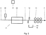
- Fig. 5 shows - schematically simplified - a side view of a part of a production line 2, with which the inventive method can be carried out according to a further embodiment.
- Fig. 5 are compared to the representation of Fig. 2 identical components provided with the same reference numerals, and therefore not explained again in detail.
- At least one first separating device 12 is provided, which is arranged upstream of a rolling stand 11 and which is viewed in the conveying direction F of the strip 1. Upstream of the first separator 12, an induction heater 20 is arranged. If a part of the belt 1 should have a deviation from a temperature-based setpoint value, the first separation device 12, in the same manner as above with respect to the Fig. 2 explained, are actuated to cut out this part of the tape 1.
- the first separator 12 By operating the first separator 12, for the purpose of severing a portion of the belt 1, which has a deviation from a temperature setpoint, the negative effects on the subsequent rolling process by a colder initial material of a by a preferably divided induction heating of spilled material can be minimized. As a result, uniform material properties are obtained over the direction of the material. In the course of this, the stability and reliability of the subsequent rolling process are also increased, as well as the losses due to transition areas with, for example, decreasing material thickness reduced. In case of plant failure, the reaction time for the completion of the casting operation is increased in a continuous rolling mill.
- the induction heater 20 according to Fig. 5 can be either in two parts (as in Fig. 3 ) or in one piece as in Fig. 4 ) be formed. To avoid repetition, the above explanation of the FIG. 3 and FIG. 4 directed.
- a straightening unit 24 may be arranged, the distance - as in Fig. 5 indicated by the double arrow - relative to the roller table 4 is variable.
- this straightening unit 24 By lowering this straightening unit 24 in the direction of the roller table 4, it can be brought into contact with the belt 1. This makes it possible that a front end of the belt 1 rests as flat as possible on the roller table 4, and thereby compensate for example, a geometric deviation in the form of a ski.
- a second separating device 13 is arranged upstream of the induction heater 24, namely in the same way as in the Fig. 2 shown and explained in detail in the appropriate place.
- the induction heater 20 may already be switched on when a front end of the belt 1 or a material beginning is passed through the induction heater 20. If the induction heater 20 is formed in two parts and their induction coils 20.1, 20.2 at a greater distance from the band. 1 If the distance of the induction coils 20.1, 20.2 relative to the belt 1 can possibly not be reduced because of its geometry, then a short-term operation of the induction heater 20 in the so-called "boost mode" is optional. possible to achieve a desired heating of the belt 1.
- the first separating device 12, which is arranged downstream of the induction heater 20, may be in the form of a so-called “flying shears" which completely separates the front end of the strip 1 or the beginning of the material in a desired length, or in individual pieces. Mutatis mutandis this also applies to the second separator 13, which may be provided upstream of the induction heater.
- control device 17 may be integrated in a (not shown) central control of the production line 2. In this case, the different processes or processes that take place when carrying out steps (a) to (d) and / or at the first or second separating device 12, 13, on the other processes in the production line 2 or the entire Casting-rolling plant tuned. If the control device 17 should be a separate module, it is understood that the control device 17 communicates suitably with the overall control of the cast-rolling plant in order to coordinate the different operating cases that take place in the production line 2.
Description
Die Erfindung betrifft ein Verfahren zur Herstellung eines metallischen Bandes im kontinuierlichen Gießwalzverfahren, bei dem zunächst eine Bramme in einer Gießmaschine gegossen und in Förderrichtung des Bandes nachgelagerten Walzwerk-Gerüsten zugeführt und hier gewalzt wird.The invention relates to a method for producing a metallic strip in the continuous casting rolling process, in which first a slab is poured in a casting machine and fed in the conveying direction of the belt downstream rolling mill stands and rolled here.
Die vorliegende Erfindung kommt demgemäß bei Gieß-Walz-Anlagen zum Einsatz, die im Endlosbetrieb aus flüssigem Metall ein fertiges Band herstellen. Für derartige Anlagen wird eine Strategie vorgeschlagen, die zum Einsatz kommen kann, wenn beabsichtigt oder unbeabsichtigt eine Unterbrechung des Walzbetriebs in Walzgerüsten des Walzwerkes auftritt.The present invention is accordingly used in cast-rolling plants which produce a finished strip from liquid metal in continuous operation. For such systems, a strategy is proposed which can be used if an interruption of the rolling operation in rolling mills of the rolling mill occurs intentionally or unintentionally.
Bekannte Gieß-Walzstraßen konvertieren flüssigen Stahl in einer kompakten Anlage zu Warmband. Dabei werden zunächst Brammen endloser Länge gegossen. Diese Brammen werden mittels Scheren zerteilt, die in ihren Abmessungen einer gewünschten Warmbundgröße entsprechen. In Wärmeöfen, oftmals als Rollenherdofen ausgeführt, werden die Brammen in der Temperatur konditioniert. Anschließend werden die Brammen einzeln einer Walzstrasse zugeführt und ausgewalzt. Anschließend werden die Bänder in einer Kühlstrecke abgekühlt und aufgehaspelt. Die Bunde verlassen die Walzlinie zur weiteren Verarbeitung.Known casting mills convert liquid steel in a compact plant to hot strip. First, slabs of endless length are poured. These slabs are cut by means of scissors which correspond in size to a desired hot-rolled size. In furnaces, often designed as a roller hearth furnace, the slabs are conditioned in temperature. Subsequently, the slabs are individually fed to a rolling train and rolled. Subsequently, the strips are cooled in a cooling section and reeled. The leagues leave the rolling line for further processing.
Bei dem so genannten Semi-Endlos-Verfahren werden die Brammen so geschnitten, dass zwei oder mehr Bunde aus dieser Bramme erzeugt werden können. Hinter dem Walzwerk ist zusätzlich eine fliegende Schere angeordnet, die das lange Warmband zerteilt, so dass die gewünschte Bundgröße erreicht wird. Mit diesem Verfahren wird die Anzahl der beim Walzen kritischen Ein- und Ausfädel-Prozesse reduziert, so dass dünnere Warmbänder sicherer erzeugt werden können.In the so-called semi-endless process, the slabs are cut so that two or more bundles can be produced from this slab. Behind the rolling mill, flying scissors are additionally arranged, which cuts the long hot strip, so that the desired waist size is achieved. With this method, the number of critical on and off rolling Reduced Ausfädel processes, so that thinner hot strips can be produced safely.
Beiden Prozessformen ist gemein, dass durch das Trennen, insbesondere Schneiden der Bramme, der Gießprozess und der Walzprozess entkoppelt stattfinden können. Die möglichen und notwendigen Prozessgeschwindigkeiten von Gießmaschine und Walzstraße sind somit unabhängig voneinander einstellbar.Both process forms have in common that can take place decoupled by the separation, in particular cutting the slab, the casting process and the rolling process. The possible and necessary process speeds of casting machine and rolling train are thus independently adjustable.
Durch die Fortschritte in der Gießmaschine und in der Prozessführung, z. B. durch Heizvorrichtungen, ist es heute möglich, auf ein Teilen der Bramme vor dem Walzen zu verzichten. Es wurde ein sog. Endlos-Herstellungs- Prozess entwickelt. Die Bramme läuft hierbei nach der Durcherstarrung unzerteilt in die Walzstraße ein, während in der Gießmaschine noch am selben Gießstrang gegossen wird. Das Zerteilen des Materials zu Bunden findet erst an der fliegenden Schere hinter der Walzstraße, und vor einem Haspelbereich, statt.Due to the progress in the casting machine and in the process management, z. B. by heaters, it is possible today to dispense with dividing the slab before rolling. A so-called endless manufacturing process has been developed. The slab runs here after solidification in one piece in the rolling mill, while cast in the casting machine still on the same cast strand. The cutting of the material into coils takes place only at the flying shears behind the rolling train, and in front of a reel area.
Es kommen also bei besagtem Endlos-Herstellungs- Prozess regelmäßig Betriebszustände vor, bei denen das Material von der Gießmaschine bis zum Haspel noch als ein physikalischer Körper verbunden ist. Der ganze Prozess findet somit kontinuierlich oder endlos statt.Thus, in the case of said endless manufacturing process, operating states occur regularly in which the material from the casting machine to the reel is still connected as a physical body. The whole process takes place continuously or endlessly.
Störungen kommen bei Anlagen dieser Größenordnung, die sich über mehrere hundert Meter erstrecken können, sporadisch vor. So muss z. B. bei Fehlfunktionen in der Warmbandstraße, an einer Schere usw. der Produktionsprozess unterbrochen werden. Die Anlage wird dann gestoppt und alle Bewegungen des Bandes bzw. der Bramme kommen zum Stillstand. Dabei kann es passieren, dass über die ganze Anlagenlänge ein unzerteilter Strang mit unterschiedlichen Bearbeitungsgraden liegt. Dadurch, dass in den verschiedenen Aggregaten (Gießmaschine, Scheren, Öfen, Walzstraße, Haspel) dieser Strang über eine Länge von 100 m und mehr liegt, ist eine Bewegung unabhängig voneinander nicht möglich.Interferences occur sporadically in systems of this size, which can extend over several hundred meters. So z. B. in case of malfunction in the hot strip mill, on a pair of scissors, etc. of the production process are interrupted. The system is then stopped and all movements of the belt or slab come to a standstill. It can happen that over the entire plant length is an undivided strand with different degrees of processing. The fact that in the various units (caster, shears, ovens, rolling mill, reel) of this strand via a Length of 100 m and more, a movement is not possible independently.
Störungen können grundsätzlich in allen Teilbereichen auftreten, d. h. im Bereich des Haspels, der fliegende Schere(n), der Fertigstraße, des Rollenherdofen usw. Ein Verwalzer in der Fertigstraße z. B. durch Bänderriss zwischen den letzten beiden Gerüsten, führt so innerhalb kürzester Zeit zu einem Materialstau zwischen diesen Gerüsten, der nur durch manuelle Tätigkeiten beseitigt werden kann. Hierzu sind zeitintensive Arbeiten notwendig mit anschließender Inspektion und ggf. Instandsetzung der Anlagenteile.Disturbances can basically occur in all subareas, ie. H. in the area of the reel, the flying shear (s), the finishing train, the roller hearth furnace, etc. A Verwalzer in the finishing mill z. B. torn ligament between the last two scaffolding, so within a very short time leads to a jam between these scaffolding, which can only be eliminated by manual activities. This requires time-consuming work with subsequent inspection and, if necessary, repair of the plant components.
Der Steuermann oder das Automationssystem stoppt im Störungsfall die Walzung. Die Gerüste werden im Allgemeinen in kürzest möglicher Zeit aufgefahren, alle Antriebe werden angehalten und der Strang kommt zum Stillstand. Da die Bramme bis zur Kokille nicht geteilt ist, gibt es Fälle, in denen auch zwangsläufig die Gießmaschine zum Stillstand kommt. Dieses Aggregat ist hierbei besonders kritisch zu sehen. Wenn der Stillstand zu lange dauert, erstarrt der Stahl in der Kokille und kann nur noch sehr aufwendig entfernt werden.The helmsman or the automation system stops rolling in the event of a fault. The scaffolds are generally driven in the shortest possible time, all drives are stopped and the strand comes to a standstill. Since the slab is not divided up to the mold, there are cases where inevitably the casting machine comes to a standstill. This unit is particularly critical to see. If the shutdown takes too long, the steel solidifies in the mold and can only be removed with great effort.
Das Entfernen des erstarrten Gießstrangs aus der Gießmaschine ist sehr zeitaufwendig und oftmals nur durch manuelles Zerteilen (z. B. Brennschneiden) möglich. Hierzu sind Kranarbeiten erforderlich und die Kokille und ggf. Teile der Stranggussanlage müssen ausgewechselt werden. Dies führt zu hohen Stillstandszeiten und Produktionseinbußen und ist zudem mit manuellen Operationen verbunden.The removal of the solidified casting strand from the casting machine is very time-consuming and often only possible by manual cutting (eg flame cutting). For this purpose, crane work is required and the mold and possibly parts of the continuous casting plant must be replaced. This leads to high downtimes and production losses and is also associated with manual operations.
Aus
Aus der
Demgemäß darf beim kontinuierlichen Gießbetrieb in einer Endlosanlage auch bei einem geplanten Walzenwechsel der Betrieb möglichst nicht unterbrochen werden. Der Strang wird abgetrennt, das abgetrennte Band wird ausgewalzt. Anschließend werden aus dem Strang Platten geschnitten und diese mittels einer Austragevorrichtung als Schrott abtransportiert.Accordingly, during continuous casting operation in an endless system, the operation should not be interrupted as much as possible even during a planned roll change. The strand is separated, the severed band is rolled out. Subsequently, slices are cut from the strand and transported away by means of a discharge device as scrap.
Der hinter der Schere gegebenenfalls gestapelte Schrott, wie es z.B. in der
Der Erfindung liegt die Aufgabe zugrunde, bei einem Gießwalzverfahren eine verbesserte Bandqualität zu gewährleisten.The invention has for its object to ensure an improved strip quality in a Gießwalzverfahren.
Die Erfindung wird gelöst durch ein Verfahren zur Herstellung eines metallischen Bandes im Gießwalzverfahren, bei dem das Band in einer Gießmaschine gegossen und anschließend in Gerüsten, die der Gießmaschine in Förderrichtung des Bandes nachgelagert sind, gewalzt wird. Hierbei ist zumindest eine erste Trenneinrichtung stromaufwärts zumindest eines ersten Walzgerüsts angeordnet. Stromaufwärts der ersten Trenneinrichtung ist eine Induktionsheizung angeordnet, derart, dass das Band zum Erwärmen in Wechselwirkung mit der Induktionsheizung gebracht wird. Ein Teil des Bandes, der eine Abweichung von einem temperaturmäßigen Sollwert aufweist, wird mittels der ersten Trenneinrichtung von dem jeweils nachfolgenden Band abgetrennt. Ein solchesThe invention is achieved by a method for producing a metal strip in the casting-rolling process, in which the strip is cast in a casting machine and then rolled in stands which are downstream of the casting machine in the conveying direction of the strip. In this case, at least one first separating device is arranged upstream of at least one first rolling mill stand. An induction heater is disposed upstream of the first separator such that the heater coil is brought into interaction with the induction heater for heating. A part of the strip which has a deviation from a temperature-based setpoint value is separated from the respective subsequent strip by means of the first separating device. Such
Abtrennen eines Teils des Bandes, der von einem Sollwert abweichende Temperaturen aufweist, bewirkt, dass dieser Teil aus der Produktionslinie entfernt und somit von dem weiteren Walzvorgang stromabwärts der Induktionsheizung ausgeschlossen ist. Der verbleibende Teil des Bandes, der die Vorgaben für eine gewünschte Temperatur erfüllt, kann dann mit vorgegebenen Walzparametern in der Walzstraße stromabwärts der ersten Trenneinrichtung gewalzt werden kann, mit gleichmäßigen Materialeigenschaften.Separating a portion of the belt having temperatures deviating from a desired value causes that part to be removed from the production line and thus excluded from further rolling downstream of the induction heating. The remaining portion of the belt that meets the specifications for a desired temperature may then be rolled with predetermined rolling parameters in the mill train downstream of the first separator, with uniform material properties.
In vorteilhafter Weiterbildung der Erfindung kann stromaufwärts der Induktionsheizung eine zweite Trenneinrichtung vorgesehen sein. Hierbei ist dann die Induktionsheizung zwischen der ersten Trenneinrichtung und der zweiten Trenneinrichtung angeordnet. Ein Teil des Bandes, der eine Abweichung von einem geometrischen Sollwert aufweist, wird mittels der zweiten Trenneinrichtung von dem jeweils nachfolgenden Band abgetrennt, und sodann aus der Produktionslinie entfernt. Hierdurch wird gewährleistet, dass Komponenten der Produktionslinie stromabwärts der zweiten Trenneinrichtung, insbesondere die Induktionsheizung, durch solche Teile des Bandes mit abweichender bzw. fehlerhafter Geometrie nicht geschädigt werden.In an advantageous embodiment of the invention may be provided upstream of the induction heater, a second separator. In this case, the induction heating is then arranged between the first separation device and the second separation device. A part of the strip which has a deviation from a geometrical desired value is separated from the respective subsequent strip by means of the second separating device, and then removed from the production line. This ensures that components of the production line downstream of the second separating device, in particular the induction heating, are not damaged by such parts of the belt with deviating or faulty geometry.
Bei Durchführung eines Gießwalzverfahrens können in der Produktionslinie unbeabsichtigte Produktionsunterbrechungen auftreten, z.B. bedingt durch Störungen. In gleicher Weise können Produktionsunterbrechungen beabsichtigt herbeigeführt werden, z.B. bedingt durch einen Walzenwechsel. Jedenfalls ist für solche Fälle durch die Erfindung gewährleistet, dass aus der Kokille und weiter aus der Gießmaschine austretender Stahl bzw. die hieraus entstehenden Brammen bzw. das hieraus gegossene Band möglichst schnell entfernt werden, um Beschädigungen von Komponenten der Produktionslinie und nachteilige Stillstandzeiten zu minimieren oder bestenfalls gar auszuschließen. Zu diesem Zweck sind zwischen dem ersten und zweiten Walzgerüst die erste Trenneinrichtung und die zweite Trenneinrichtung angeordnet, die das Band in dem Bereich zwischen dem ersten und zweiten Walzgerüst durchschneiden,
wobei das Band in einen Zwischenabschnitt, einen Stromabwärts-Abschnitt und einen Stromaufwärts-Abschnitt unterteilt wird. Hierbei ist es zweckmäßig, wenn die erste und zweite Trenneinrichtung gleichzeitig betätigt werden.When carrying out a casting rolling process, unintentional production interruptions may occur in the production line, eg due to faults. In the same way production interruptions can be intentionally brought about, for example due to a roll change. In any case, it is ensured for such cases by the invention that steel emerging from the mold and further from the casting machine or the slabs or the strip cast therefrom are removed as quickly as possible in order to minimize damage to components of the production line and disadvantageous downtimes or at best even exclude. For this purpose, the first separating device and the second separating device are arranged between the first and second rolling stands, which cut through the strip in the region between the first and second rolling stand,
wherein the band is divided into an intermediate portion, a downstream portion and an upstream portion. It is expedient if the first and second separating device are actuated simultaneously.
In Bezug auf die Abschnitte, in welche das Band geschnitten bzw. unterteilt wird, darf darauf hingewiesen werden, dass sich der Zwischenabschnitt des Bandes zwischen der ersten und zweiten Trenneinrichtung befindet. Bei dem Stromabwärts-Abschnitt handelt es sich um den Teil des Bandes, der sich stromabwärts der ersten Trenneinrichtung befindet. Der Stromaufwärts-Abschnitt ist der Teil des Bandes, der sich stromaufwärts der zweiten Trenneinrichtung befindet.With respect to the portions into which the band is cut, it should be noted that the intermediate portion of the band is between the first and second separators. The downstream section is that part of the belt that is downstream of the first separator. The upstream section is that part of the belt that is upstream of the second separator.
Der Erfindung liegt die wesentliche Erkenntnis zugrunde, dass es beim Auftreten einer Störung oder Produktionsunterbrechung im Walzwerk möglich ist, mit einem Durchschneiden des Bandes mittels der Trenneinrichtungen und einem anschließenden Zerhäckseln der jeweiligen Abschnitte des Bandes, oder einem Schneiden der jeweiligen Abschnitte des Bandes in Teile mit einer vorbestimmten Länge in Verbindung mit einem Stapeln dieser Bandteile, einen "Stau" des Bandes innerhalb des Walzwerks, und somit Schädigungen an Walzgerüsten und weiteren Komponenten der Produktionslinie zu verhindern. In gleicher Weise ist es hierdurch möglich, Stillstandszeiten innerhalb der Produktionslinie zu minimieren oder gar zu vermeiden. Somit ist es durch die vorliegende Erfindung möglich, im Falle einer im Walzwerk auftretenden Störung oder Unterbrechung Bandverluste zu minimieren, und - nach Beseitigung der Störung - in kurzer Zeit zu dem normalen Endlosbetrieb zurückzugelangen.The invention is based on the essential finding that it is possible in the event of a malfunction or interruption of production in the rolling mill, with a cutting of the tape by means of the separating devices and a subsequent chop-cutting of the respective sections of the strip, or a cutting of the respective sections of the strip into parts with a predetermined length in connection with stacking these band parts, a "jam" of the band within the rolling mill, and thus to prevent damage to rolling stands and other components of the production line. In the same way, this makes it possible to minimize or even avoid downtimes within the production line. Thus, it is possible by the present invention, in the event of malfunction or interruption occurring in the rolling mill to minimize band losses, and - after elimination of the disturbance - to get back to the normal continuous operation in a short time.
In vorteilhafter Weiterbildung der Erfindung können die Betätigungen der Trenneinrichtungen mittels einer Steuerungseinrichtung durchgeführt werden. Dies bedeutet, dass mittels der Steuerungseinrichtung ein Betrieb der Trenneinrichtungen gewährleistet ist.In an advantageous embodiment of the invention, the actuations of the separating means can be carried out by means of a control device. This means that by means of the control device, an operation of the separating devices is ensured.
Somit ist es mit Hilfe der Steuerungseinrichtung möglich, das erfindungsgemäße Verfahren vollautomatisch auszuführen, beispielsweise solange, bis der Zwischenabschnitt des Bandes vollständig aus dem Bereich zwischen der ersten und zweiten Trenneinrichtung entfernt worden ist, und auch die Störung im Walzwerk behoben worden ist.Thus, it is possible with the aid of the control device to carry out the inventive method fully automatically, for example, until the intermediate portion of the tape has been completely removed from the area between the first and second separator, and the disturbance in the rolling mill has been resolved.
In vorteilhafter Weiterbildung der Erfindung können in dem Walzwerk Sensoreinrichtungen integriert sein, mittels derer eine Störung im Walzbetrieb erkannt wird. Für diesen Fall wird ein Betrieb insbesondere der zweiten Trenneinrichtung mittels der Steuerungseinrichtung vollautomatisch durchgeführt, oder kann von dem Bedienpersonal einzeln bestätigt werden.In an advantageous embodiment of the invention may be integrated in the rolling mill sensor devices by means of which a fault is detected in the rolling operation. For this case, an operation, in particular the second separating device by means of the control device is carried out fully automatically, or can be confirmed individually by the operator.
In vorteilhafter Weiterbildung der Erfindung kann das Verfahren nach der vorliegenden Erfindung in der Weise gesteuert werden, dass umfangreiche Algorithmen für unterschiedliche Störfälle in der Anlagensteuerung bzw. der vorgenannten Steuerungseinrichtung abgelegt sind. Bei Erkennung einer Anlagenstörung durch das Bedienpersonal oder durch die in das Walzwerk integrierten Sensoreinrichtungen werden anhand einer Entscheidungsmatrix alle zur Verfügung stehenden Anlagenteile vollautomatisch oder teilautomatisch in der Weise angesteuert, dass eine für den jeweiligen Betriebsfall optimale Strategie eingeleitet und aufrechterhalten wird.In an advantageous embodiment of the invention, the method according to the present invention can be controlled in such a way that extensive algorithms for different incidents in the system control or the aforementioned control device are stored. Upon detection of a system malfunction by the operating personnel or by the integrated in the rolling mill sensor means all available parts of the system are fully automatically or semi-automatically controlled in a manner based on a decision that an optimal for the respective operating case strategy is initiated and maintained.
In vorteilhafter Weiterbildung der Erfindung kann - in Förderrichtung des Bandes gesehen - stromaufwärts der Induktionsheizung eine Richteinrichtung, z.B. in Form eines Richtaggregats oder eines Einfuhrtrichters, angeordnet sein. Bevor das Band in die Induktionsheizung einläuft, wird diese Richteinrichtung in Kontakt mit dem Band gebracht, so dass das Band möglichst plan auf dem Rollgang aufliegt. Eine solche Richteinrichtung ist insbesondere für den Fall empfehlenswert, wenn ein Vorderende des Bandes eine geometrische Abweichung nach Art eines "Ski" aufweist.In an advantageous embodiment of the invention can - viewed in the conveying direction of the belt - upstream of the induction heating a straightening device, for example in the form of a straightening unit or an insertion funnel, be arranged. Before the belt enters the induction heating, this straightening device is brought into contact with the belt, so that the belt rests as flat as possible on the roller table. Such a straightening device is particularly recommended for the case when a front end of the band has a geometric deviation in the manner of a "ski".
In vorteilhafter Weiterbildung der Erfindung kann die Induktionsheizung für einen sog. "Boost-Modus" ausgelegt sein, d.h. für einen Betrieb mit einer kurzzeitigen Überlastung. Durch eine solche Betriebsweise der Induktionsheizung kann das Band, und insbesondere dessen Vorderende beim Auswalzen eines neuen Bandes, intensiver erwärmt werden, wobei einem Übertragungsverlust, der sich aus einem möglicherweise größeren Abstand der Induktionsheizung von dem Band ergibt, wirkungsvoll entgegengewirkt wird.In an advantageous embodiment of the invention, the induction heating can be designed for a so-called "boost mode", i. for operation with a short-term overload. Such an operation of induction heating can more intensively heat the strip, and in particular the front end thereof, when a new strip is rolled out, effectively counteracting a transmission loss resulting from a possibly greater distance of the induction heating from the strip.
In vorteilhafter Weiterbildung der Erfindung, beispielsweise als Alternative zu dem soeben genannten "Boost-Modus", ist es möglich, für die Induktionsheizung Induktionsspulen mit höherer Leistung vorzusehen, und/oder in der Induktionsheizung zusätzliche Induktionsspulen einzusetzen. Im Ergebnis kann hierdurch entweder eine intensivere Erwärmung des Bandes bei gleichbleibenden Beabstandung der Induktionsheizung zu dem Band, oder eine gleichbleibende Erwärmung des Bandes, wenn eine Beanstandung der Induktionsheizung zu dem Band vergrößert wird, erreicht werden.In an advantageous embodiment of the invention, for example as an alternative to the "boost mode" just mentioned, it is possible to provide induction coils with higher power for the induction heating, and / or to use additional induction coils in the induction heating. As a result, either a more intense heating of the belt with a constant spacing of the induction heating to the belt, or a constant heating of the belt, if a complaint of the induction heating is increased to the band, can be achieved.
Weitere Vorteile der Erfindung ergeben sich durch folgende Aspekte:
- Einsatz einer Induktionsheizung, deren Spulen einzeln oder in Gruppe in der Höhe verstellt werden können;
- Einsatz einer Trommelschere mit mehreren auf den Messertrommeln angeordneten Messerpaaren für das Häckseln des Materialanfangs;
- Entsorgen der Materialanfangs in einer Aufnahmevorrichtung, z.B. einen oder mehrere Schrottbehälter unter der Anlage, die mit einem Kran entleert werden können;
- Einsatz eines übergeordneten Steuerungssystem zur Ermittlung der Eigenschaften am Materialanfang und Bestimmung der Länge des abzutrennenden Materialanfangs;
- Berücksichtigung unterschiedlicher Materialeigenschaften und Materialabmessungen bei der Bestimmung der Länge des abzutrennenden Materialsanfangs durch das Steuerungssystem; und
- Möglichkeit der Beinflussung der Länge des abzutrennenden Materialanfangs durch das Bedienpersonal.
- Use of an induction heater whose coils can be adjusted individually or in groups in height;
- Use of a drum shears with several arranged on the knife drums knife pairs for chopping the beginning of material;
- Disposing of the beginning of the material in a receiving device, for example one or more scrap containers under the plant, which can be emptied by a crane;
- Use of a higher-level control system for determining the properties at the beginning of the material and determination of the length of the material beginning to be separated;
- Consideration of different material properties and material dimensions in determining the length of the material to be separated beginning by the control system; and
- Possibility of influencing the length of the beginning of the material to be separated by the operating personnel.
Nachstehend sind Ausführungsbeispiele der Erfindung anhand einer schematisch vereinfachten Zeichnung im Detail beschrieben.Embodiments of the invention are described in detail with reference to a schematically simplified drawing.
Es zeigen:
- Fig. 1
- eine Seitenansicht eines Teils einer Gieß-Walz-Anlage, zur Durchführung eines Verfahrens gemäß der vorliegenden Erfindung,
- Fig. 2
- eine schematische Darstellung der Gieß-Walz-Anlage von
Fig. 1 , - Fig. 3
- eine schematische Stirnseitenansicht einer zweiteiligen Induktionsheizung, die in eine Gieß-Walz-Anlage von
Fig. 1 integriert sein kann, - Fig. 4
- eine schematische Stirnseitenansicht einer Induktionsheizung, die in eine Gieß-Walz-Anlage von
Fig. 1 integriert sein kann, und - Fig. 5
- eine schematische Seitenansicht eines Teils einer Gieß-Walz-Anlage, zur Durchführung eines erfindungsgemäßen Verfahrens nach einer weiteren Ausführungsform.
- Fig. 1
- a side view of a part of a casting-rolling plant, for carrying out a method according to the present invention,
- Fig. 2
- a schematic representation of the casting-rolling plant of
Fig. 1 . - Fig. 3
- a schematic end view of a two-part induction heating, in a casting-rolling plant of
Fig. 1 can be integrated - Fig. 4
- a schematic end view of an induction heater, which in a casting-rolling plant of
Fig. 1 can be integrated, and - Fig. 5
- a schematic side view of a portion of a casting-rolling plant, for carrying out a method according to the invention according to a further embodiment.
Die Förderrichtung, mit der das Band 1 durch die Produktionslinie 2 bewegt wird, ist in der
Nachstehend sind die wesentlichen Komponenten der Produktionslinie 2 erläutert:
Es sind Gerüste vorgesehen, nämlich ein erstes Walzgerüst 10 und - stromabwärts hiervon - ein zweites Walzgerüst 11. Zwischen diesen Walzgerüsten 10, 11 sind eine erste Trenneinrichtung 12 und eine zweite Trenneinrichtung 13 angeordnet. Hierbei befindet sich die zweite Trenneinrichtung 3 - in Förderrichtung F des Bandes 1 - stromaufwärts von der ersten Trenneinrichtung 12.The main components of
Scaffolds are provided, namely a first rolling
Unterhalb der Trenneinrichtungen 12, 13 sind Sammelräume 14 vorgesehen, in denen jeweils eine Aufnahmevorrichtung 16 eingebracht werden kann. Die Funktionsweise dieser Aufnahmevorrichtungen 16 ist nachstehend noch im Detail erläutert.Below the separating
Die Produktionslinie 2 ist mit einer Steuerungseinrichtung 17 ausgerüstet, mit der die wesentlichen Komponenten der Produktionslinie 2 geeignet angesteuert werden können. Die Steuerungseinrichtung 17 ist in der
In der Produktionslinie 2 sind Treibereinrichtungen 18, 19 vorgesehen, mittels derer das Band 1 auf einem Rollgang 4 der Produktionslinie 2 transportiert bzw. gefördert werden kann.In the
Stromabwärts der ersten Trenneinrichtung 12 ist in die Produktionslinie 2 ein Zunderwäscher 22 integriert.Downstream of the
Die vorstehend genannten Komponenten der Produktionslinie 2 von
Ein Verfahren gemäß der vorliegenden Erfindung kann bei einer Produktionslinie 2 gemäß
Falls innerhalb der Produktionslinie 2, oder in (nicht gezeigten) Walzgerüsten oder anderen Komponenten der Walzstrasse stromabwärts davon, eine Störung oder Produktionsunterbrechung auftritt, werden die vorstehend bereits erläuterten Schritte (a) bis (d) durchgeführt. Im Einzelnen werden im Schritt (a) die beiden Trenneinrichtungen 12, 13 vorzugsweise gleichzeitig betätigt, um das Band 1 an diesen Stellen durchzuschneiden. Hierdurch werden ein Zwischenabschnitt Z, der zwischen der ersten und zweiten Trenneinrichtung 12, 13 verbleibt, ein Stromabwärts-Abschnitt I, der sich stromabwärts der ersten Trenneinrichtung 12 befindet, und ein Stromaufwärts-Abschnitt II, der sich stromaufwärts der zweiten Trenneinrichtung 13 befindet, gebildet. Anschließend wird, in Schritt (b), der Stromabwärts-Abschnitt I des Bands 1, vorzugsweise durch eine Betätigung der stromabwärts der ersten Trenneinrichtung 12 angeordneten Treibereinrichtung 19, weg von der ersten Trenneinrichtung 12 gefördert, nämlich in der Förderrichtung F. Hierdurch wird die erste Trenneinrichtung 12 von dem Stromabwärts-Abschnitt I "freigemacht", und kann dann erneut betätigt werden. Entsprechend wird der Zwischenabschnitt Z des Bands 1, in Schritt (c), mittels der Treibereinrichtung 18 in Richtung der ersten Trenneinrichtung 12 gefördert, und dann mittels der ersten Trenneinrichtung 12 durchgeschnitten. Bei diesem Durchschneiden mittels der ersten Trenneinrichtung 12 kann der Zwischenabschnitt Z des Bands 1 zerhäckselt werden, wobei dann die zerhäckselten Teile des Zwischenabschnitts Z nach unten in eine Aufnahmevorrichtung 16 in Form eines Schrottbehälters fallen, der in den unterhalb der ersten Trenneinrichtung 12 vorgesehenen Sammelraum 14 eingeschoben ist.A method according to the present invention may be used in a
If a disturbance or stoppage of production occurs within the
Der Stromaufwärts-Abschnitt II des Bands 1, der sich stromaufwärts der zweiten Trenneinrichtung 13 befindet und von dort in Richtung der zweiten Trenneinrichtung 13 stetig nachgefördert wird, wird in Schritt (d) mittels der zweiten Trenneinrichtung 13 durchgeschnitten. Bei diesem Durchschneiden kann der Stromaufwärts-Abschnitt II ebenfalls zerhäckselt werden, wobei die Bandhäcksel nach unten in eine Aufnahmevorrichtung 16 fallen, die in den unterhalb der zweiten Trenneinrichtung 13 vorgesehenen Sammelraum 14 eingeschoben ist.The upstream portion II of the
In Bezug auf die Schrottbehälter 16, die in die jeweiligen Sammelräume 14 zur Aufnahme der zerhäckselten Bandabschnitte eingebracht sind, versteht sich, dass diese Schrottbehälter 16, nach vollständiger Befüllung, ausgetauscht werden können.With regard to the
Alternativ zu dem soeben genannten Zerhäckseln der Abschnitte des Bandes 1 mittels der ersten und zweiten Trenneinrichtung 12, 13 ist es auch möglich, diese Abschnitte des Bands 1 mittels der Trenneinrichtungen 12, 13 in Teile mit einer vorbestimmten Länge abzutrennen, und anschließend zu Platten zu stapeln. Für diesen Fall können in den Sammelräumen 14, anstatt der Schrottbehälter 16, geeignete Stapeleinrichtungen (in der Zeichnung nicht gezeigt) vorgesehen sein.As an alternative to the just-mentioned chopping of the sections of the
Nachstehend sind weitere Komponenten für die Produktionslinie 2 erläutert, auf Grundlage derer das erfindungsgemäße Verfahren nach einer weiteren Ausführungsform ausgeführt werden kann.Below, further components are explained for the
Im Bereich zwischen der ersten Trenneinrichtung 12 und der zweiten Trenneinrichtung 13 ist eine Induktionsheizung 20 angeordnet. In Wechselwirkung mit dieser Induktionsheizung 20 kann das Band 1 innerhalb der Produktionslinie 2 gezielt erwärmt werden. Die Induktionsheizung 20 kann geteilt ausgebildet sein: Ausweislich der schematisch vereinfachten Stirnseitenansicht von
Gemäß einer alternativen Ausführungsform kann die Induktionsheizung 20 auch einteilig ausgebildet sein, wie schematisch vereinfacht in der Stirnseitenansicht von
Bevor in der Produktionslinie 2 ggf. eine Produktionsunterbrechung auftritt und dann wie erläutert die Schritte (a) bis (d) durchgeführt werden, kann ein Walzen des Bandes 1 in der Produktionslinie 2, gemäß einer weiteren Ausführungsform des erfindungsgemäßen Verfahrens, dadurch optimiert werden, dass ein Teil des Bandes 1, der eine von einem vorbestimmten Sollwert abweichende Temperatur aufweist, mittels der ersten Trenneinrichtung 12 herausgeschnitten wird. Dies hat zur Folge, dass ein solcher Art herausgeschnittener Teil des Bandes 1 in den Walzgerüsten stromabwärts der ersten Trenneinrichtung 12 nicht mehr gewalzt wird, sondern stattdessen in den Sammelraum unterhalb der ersten Trenneinrichtung 12 hineinfällt. Hierdurch ist sichergestellt, dass stromabwärts der ersten Trenneinrichtung 12 der nachfolgende Teil des Bandes 1 ausschließlich mit einer vorbestimmten Temperatur gewalzt wird, was zu einer erhöhten Produktqualität führt.Before a production stoppage occurs in the
Des Weiteren kann vorgesehen sein, dass ein Teil des Bandes 1, der eine Abweichung von einem geometrischen Sollwert aufweist, mittels der zweiten Trenneinrichtung 13 von dem jeweils nachfolgenden Band 1 abgetrennt wird. Hierdurch ist gewährleistet, dass geometrische Abweichungen des Bandes 1, die in Form eines Keils, Säbels oder Skis insbesondere an einem Vorderende des Bandes 1 auftreten können, aus dem Band 1 herausgeschnitten werden, so dass eine mögliche Schädigung von Anlagenkomponenten der Walzstrasse durch diese Abweichungen ausgeschlossen ist, bzw. der Walzprozess stromabwärts der zweiten Trenneinrichtung 13 durch diese Abweichungen nicht beeinträchtigt wird.Furthermore, it can be provided that a part of the
In Bezug auf eine Betätigung der ersten Trenneinrichtung 12, nämlich zum Abtrennen eines Teils des Bandes 1, der eine Abweichung von einem temperaturmäßigen Sollwert aufweist, und der zweiten Trenneinrichtung 13, nämlich zum Abtrennen eines Teils des Bandes 1, der eine Abweichung von einem geometrischen Sollwert aufweist, darf darauf hingewiesen werden, dass dies auch unabhängig von der Durchführung der Schritte (a) bis (b) möglich ist.With respect to an operation of the
Bei der Produktionslinie 2 gemäß
Durch die Betätigung der ersten Trenneinrichtung 12, zwecks Abtrennen eines Teils des Bands 1, der eine Abweichung von einem temperaturmäßigen Sollwert aufweist, können die negativen Auswirkungen auf den nachfolgenden Walzprozess durch einen kälteren Materialanfang eines durch eine vorzugsweise geteilte Induktionsheizung gelaufenen Materials minimiert werden. Hierdurch werden gleichmäßige Materialeigenschaft über die Laufrichtung des Materials erhalten. Im Zuge dessen werden auch die Stabilität und Betriebssicherheit des nachfolgenden Walzprozesses erhöht, als auch die Verluste durch Übergangsbereiche mit z.B. abnehmender Materialdicke reduziert. Im Anlagenstörfall wird die Reaktionszeit für die Beendigung des Gießbetriebs bei einer Endloswalzanlage erhöht.By operating the
Die Induktionsheizung 20 gemäß
Stromaufwärts der Induktionsheizung 20 kann bei der Produktionslinie 2 gemäß
Bei der Produktionslinie 2 gemäß
Die Induktionsheizung 20 kann bereits eingeschaltet sein, wenn ein Vorderende des Bands 1 bzw. ein Materialanfang durch die Induktionsheizung 20 hindurchgeführt wird. Falls die Induktionsheizung 20 zweiteilig ausgebildet ist und dabei deren Induktionsspulen 20.1, 20.2 auf einen größeren Abstand zum Band 1 eingestellt sind, erfolgt dennoch bereits eine Erwärmung des Bandes 1. Falls ein Abstand der Induktionsspulen 20.1, 20.2 relativ zum Band 1 ggf. wegen dessen Geometrie nicht vermindert werden kann, ist optional ein kurzzeitiger Betrieb der Induktionsheizung 20 im sog. "Boost-Modus" möglich, um eine gewünschte Erwärmung des Bandes 1 zu erzielen.The
Die erste Trenneinrichtung 12, die stromabwärts von der Induktionsheizung 20 angeordnet ist, kann in Form einer sog. "fliegenden Schere" ausgebildet sein, die das Vorderende des Bandes 1 bzw. den Materialanfang in einer gewünschten Länge komplett, oder in einzelnen Stücken, abtrennt. Mutatis mutandis gilt dies auch für die zweite Trenneinrichtung 13, die stromaufwärts der Induktionsheizung vorgesehen sein kann.The
Eine Ansteuerung der Trenneinrichtungen 12, 13, der Treibereinrichtungen 18, 19 und auch der Induktionsspulen 20.1, 20.2 zu deren Höhenverstellung ist jeweils mittels der Steuerungseinrichtung 17 möglich, indem die Steuerungseinrichtung 17 mit diesen Komponenten signaltechnisch verbunden ist.An activation of the
Schließlich darf gesondert darauf hingewiesen werden, dass die Steuerungseinrichtung 17 in eine (nicht gezeigte) Zentralsteuerung der Produktionslinie 2 integriert sein kann. Für diesen Fall werden die unterschiedlichen Vorgänge bzw. Abläufe, die bei Durchführung der Schritte (a) bis (d) und/oder an der ersten bzw. zweiten Trenneinrichtung 12, 13 stattfinden, auf die übrigen Abläufe in der Produktionslinie 2 bzw. der gesamten Gieß-Walz-Anlage abgestimmt. Falls es sich bei der Steuerungseinrichtung 17 um ein gesondertes Modul handeln sollte, so versteht sich, dass die Steuerungseinrichtung 17 geeignet mit der Gesamtsteuerung der Gieß-Walz-Anlage kommuniziert, zwecks Abstimmung der unterschiedlichen Betriebsfälle, die in der Produktionslinie 2 stattfinden.Finally, it should be noted separately that the
- 11
- Bandtape
- 22
- Produktionslinieproduction line
- 44
- Rollgangroller table
- 66
- Vorwalzwerkroughing mill
- 88th
- FertigwalzwerkFinishing mill
- 1010
- erstes Walzgerüstfirst rolling stand
- 1111
- zweites Walzgerüstsecond rolling stand
- 1212
- erste Trenneinrichtungfirst separator
- 1313
- zweite Trenneinrichtungsecond separator
- 1414
- Sammelraumplenum
- 1616
- Aufnahmevorrichtungcradle
- 1717
- Steuerungseinrichtungcontrol device
- 18, 1918, 19
- Treibereinrichtungdriving means
- 20.120.1
- Induktionsspule/oberhalbInductor / above
- 20.220.2
- Induktionsspule/unterhalbInductor / below
- 2222
- Zunderwäscherdescaling
- 2424
- Richteinrichtungleveler
- FF
- Förderrichtungconveying direction
- HH
- Höhe (der Induktionsspulen, bezüglich des Band 1)Height (of the induction coils, with respect to the band 1)
- ZZ
-
Zwischenabschnitt des Bandes 1Intermediate section of the
tape 1 - II
-
Stromabwärts-Abschnitt des Bandes 1Downstream section of the
tape 1 - IIII
-
Stromaufwärts-Abschnitt des Bandes 1Upstream section of the
belt 1
Claims (7)
- Method of producing a metallic strip (1) in a casting and rolling method, in which the strip (1) is cast in a casting machine and subsequently rolled in rolling mill stands downstream of the casting machine in conveying direction (F) of the strip (1), wherein at least one first separating device (12) arranged upstream of at least a first roll stand (10) is provided, wherein an induction heating means (20) is so arranged upstream of the first separating device (12) in conveying direction (F) of the strip (1) that, for heating, the strip (1) is brought into interaction with the induction heating means (20), characterised in that a part of the strip (1) having a deviation from a target value in terms of temperature is separated from the respective succeeding strip (1) by means of the first separating device (12).
- Method according to claim 1, characterised in that a second separating device (13) is arranged upstream of the induction heating means (20), wherein the induction heating means (20) is arranged between the first separating device (12) and the second separating device (13) and wherein a part of the strip (1) having a deviation from a geometric target value is separated from the respective succeeding strip (1) by means of the second separating device (13).
- Method according to claim 1 or 2, characterised in that the induction heating means (20) is of divided construction, wherein induction coils of the induction heating means (20) are arranged not only above (20.1), but also below (20.2) the strip (1), the induction coils (20.1, 20.2) preferably being adjustable above and below the strip (1) respectively independently of one another in the spacing thereof from the strip (1) so as to set a predetermined height (H) from the strip (1).
- Method according to any one of claims 1 to 3, characterised in that a straightening device (24) is arranged upstream of the induction heating means (20) in conveying direction (F) of the strip (1) and can be brought into contact with the strip (1), preferably with a front end of the strip (1), in such a way that the strip (1), preferably the front end thereof, through the contact with the straightening device (24) rests flatly on a roller path (4) of the rolling mill, the straightening device (24) preferably being constructed in the form of a straightening unit or an introducing funnel.
- Method according to any one of claims 1 to 4, characterised in that the induction heating means (20) is temporarily operated in an overload mode so as to sufficiently heat the strip (1), preferably a front end thereof.
- Method according to any one of claims 1 to 5, characterised in that additional induction coils (20.1, 20.2) are integrated in the induction heating means (20).
- Method according to any one of claims 1 to 6, characterised in that the first separating device (12) is activated in dependence on a temperature of the strip (1) or the second separating device (13) is activated in dependence on geometric dimensions of the strip (1), the strip (1) preferably being cut by the first separating device (12) and/or by the second separating device (13) into parts each with a predetermined defined length.
Applications Claiming Priority (2)
| Application Number | Priority Date | Filing Date | Title |
|---|---|---|---|
| DE102015208733 | 2015-05-11 | ||
| PCT/EP2016/060567 WO2016180882A1 (en) | 2015-05-11 | 2016-05-11 | Method for producing a metallic strip in a casting and rolling process |
Publications (2)
| Publication Number | Publication Date |
|---|---|
| EP3294470A1 EP3294470A1 (en) | 2018-03-21 |
| EP3294470B1 true EP3294470B1 (en) | 2019-07-10 |
Family
ID=55953172
Family Applications (1)
| Application Number | Title | Priority Date | Filing Date |
|---|---|---|---|
| EP16721446.9A Active EP3294470B1 (en) | 2015-05-11 | 2016-05-11 | Method for producing a metallic strip in a casting and rolling process |
Country Status (4)
| Country | Link |
|---|---|
| EP (1) | EP3294470B1 (en) |
| JP (1) | JP2018518369A (en) |
| DE (1) | DE102016208114A1 (en) |
| WO (1) | WO2016180882A1 (en) |
Families Citing this family (4)
| Publication number | Priority date | Publication date | Assignee | Title |
|---|---|---|---|---|
| JP6684968B2 (en) * | 2016-11-10 | 2020-04-22 | エス・エム・エス・グループ・ゲゼルシャフト・ミト・ベシュレンクテル・ハフツング | Method for producing metallic strip in a continuous casting and rolling plant |
| CN107186266B (en) * | 2017-06-01 | 2019-09-27 | 平湖市超越时空图文设计有限公司 | One kind is for quantitative steel pipe cutting and transmission equipment |
| CN108247414A (en) * | 2018-03-21 | 2018-07-06 | 吴江市和信机械制造厂 | A kind of metallic plate cutter device |
| CN112077272B (en) * | 2019-06-12 | 2021-06-15 | 宝山钢铁股份有限公司 | Electromagnetic stirring device and method for slab continuous casting secondary cooling area |
Family Cites Families (17)
| Publication number | Priority date | Publication date | Assignee | Title |
|---|---|---|---|---|
| JPS63157750A (en) | 1986-12-22 | 1988-06-30 | Hitachi Ltd | Strip production apparatus |
| JPH01224102A (en) | 1988-03-02 | 1989-09-07 | Hitachi Ltd | Facility for continuous casting and rolling of thin sheet |
| JPH05277539A (en) | 1991-07-09 | 1993-10-26 | Nkk Corp | Strip sampling device |
| DE4220424C2 (en) | 1992-06-22 | 1999-03-04 | Eko Stahl Gmbh | Device for separating a damaged thin slab |
| ATE163370T1 (en) | 1993-05-17 | 1998-03-15 | Danieli Off Mecc | PRODUCTION LINE FOR THE PRODUCTION OF STRIPS AND/OR SHEET |
| DE19856767A1 (en) | 1998-11-30 | 2000-05-31 | Mannesmann Ag | Reel arrangement for winding thinly rolled finished strip |
| US6296047B1 (en) * | 1999-05-21 | 2001-10-02 | Danieli Technology, Inc. | Endless casting rolling system with single casting stand |
| JP4366825B2 (en) | 2000-03-30 | 2009-11-18 | Jfeスチール株式会社 | Crop shear for joining, hot rolling equipment line and hot rolling method |
| KR101148375B1 (en) * | 2006-10-31 | 2012-05-24 | 도시바 미쓰비시덴키 산교시스템 가부시키가이샤 | Hot rolling device |
| DE102007058709A1 (en) * | 2007-08-04 | 2009-02-05 | Sms Demag Ag | Method for producing a strip of steel |
| AT506603B8 (en) * | 2008-04-04 | 2010-03-15 | Siemens Vai Metals Tech Gmbh | METHOD AND DEVICE FOR A CAST IRONING COMPOSITE |
| DE102009018683A1 (en) * | 2009-04-23 | 2010-10-28 | Sms Siemag Ag | Method and device for continuous casting of a slab |
| EP2428288B1 (en) * | 2010-09-08 | 2013-04-17 | Siemens VAI Metals Technologies GmbH | Method for producing steel bands using continuous casting or semi-continuous casting |
| AT513299B1 (en) * | 2012-08-20 | 2016-04-15 | Primetals Technologies Austria GmbH | Method and device for a cast-rolled composite plant |
| JP2014175082A (en) * | 2013-03-06 | 2014-09-22 | Jfe Steel Corp | Induction heating apparatus and induction heating method |
| RU2630106C2 (en) * | 2013-03-08 | 2017-09-05 | Смс Груп Гмбх | Method of manufacture of metal strip by continuous casting and rolling |
| DE102014224231A1 (en) | 2014-01-03 | 2015-07-09 | Sms Siemag Ag | Method and device for producing a metallic strip in a continuous casting-rolling process |
-
2016
- 2016-05-11 DE DE102016208114.4A patent/DE102016208114A1/en active Pending
- 2016-05-11 EP EP16721446.9A patent/EP3294470B1/en active Active
- 2016-05-11 WO PCT/EP2016/060567 patent/WO2016180882A1/en active Application Filing
- 2016-05-11 JP JP2017559015A patent/JP2018518369A/en active Pending
Non-Patent Citations (1)
| Title |
|---|
| None * |
Also Published As
| Publication number | Publication date |
|---|---|
| JP2018518369A (en) | 2018-07-12 |
| DE102016208114A1 (en) | 2016-11-17 |
| EP3294470A1 (en) | 2018-03-21 |
| WO2016180882A1 (en) | 2016-11-17 |
Similar Documents
| Publication | Publication Date | Title |
|---|---|---|
| EP2259886B1 (en) | Method and apparatus for a combined casting-rolling installation | |
| EP2176010B1 (en) | Method for the production of a strip made of steel | |
| EP3294470B1 (en) | Method for producing a metallic strip in a casting and rolling process | |
| EP2964404B1 (en) | Method for producing a metal strip by casting and rolling | |
| EP3024601B1 (en) | Method and device for producing a metallic strip in a continuous casting and rolling process | |
| DE202011110781U1 (en) | Plant for the production of flat rolled products | |
| EP3507030B1 (en) | Continuously operable production plant and method for operating the production plant when there is a fault | |
| EP2885091B1 (en) | Method and device for a combined continuous casting and rolling system | |
| EP2427281B1 (en) | Method for producing a milling product milled in a mill train of a mill assembly, control and/or regulating device for a mill assembly for producing milled products and/or milled product section, mill assembly for producing milled products, machine readable program code and storage medium | |
| EP3099437B1 (en) | Metallurgical system with roller section that can be lowered on one side | |
| EP3341142B1 (en) | Method for operating an installation based on the csp concept | |
| AT513298B1 (en) | Interstate area of a cast-rolled composite plant | |
| EP3089832B1 (en) | Method and device for producing a metal strip in a continuous casting and rolling process | |
| EP2663412B1 (en) | Equipment and method for producing hot-rolled strips | |
| EP2767600A1 (en) | Method, especially for the production of long steel products and device for implementing the method | |
| WO2015000968A1 (en) | Cast-rolling installation and method for producing metallic rolled stock | |
| EP3027331B1 (en) | Casting and rolling plant and method for producing slabs | |
| DE3120464A1 (en) | Method and device for optimised cut distribution in the cutting of bars into extrusion billets | |
| DE4323837A1 (en) | Automated high-speed rolls | |
| DE102020206340A1 (en) | Plant for the production of metal strips and processes for their operation | |
| EP3725450A2 (en) | Method and device for producing a composite material with multiple coatings | |
| EP3790688A1 (en) | Casting and rolling plant, and method for operating the same | |
| DE112011105376T5 (en) | Hot sheet material manufacturing facility and hot sheet material manufacturing process |
Legal Events
| Date | Code | Title | Description |
|---|---|---|---|
| STAA | Information on the status of an ep patent application or granted ep patent |
Free format text: STATUS: THE INTERNATIONAL PUBLICATION HAS BEEN MADE |
|
| PUAI | Public reference made under article 153(3) epc to a published international application that has entered the european phase |
Free format text: ORIGINAL CODE: 0009012 |
|
| STAA | Information on the status of an ep patent application or granted ep patent |
Free format text: STATUS: REQUEST FOR EXAMINATION WAS MADE |
|
| 17P | Request for examination filed |
Effective date: 20171211 |
|
| AK | Designated contracting states |
Kind code of ref document: A1 Designated state(s): AL AT BE BG CH CY CZ DE DK EE ES FI FR GB GR HR HU IE IS IT LI LT LU LV MC MK MT NL NO PL PT RO RS SE SI SK SM TR |
|
| AX | Request for extension of the european patent |
Extension state: BA ME |
|
| DAV | Request for validation of the european patent (deleted) | ||
| DAX | Request for extension of the european patent (deleted) | ||
| GRAP | Despatch of communication of intention to grant a patent |
Free format text: ORIGINAL CODE: EPIDOSNIGR1 |
|
| STAA | Information on the status of an ep patent application or granted ep patent |
Free format text: STATUS: GRANT OF PATENT IS INTENDED |
|
| INTG | Intention to grant announced |
Effective date: 20190109 |
|
| GRAS | Grant fee paid |
Free format text: ORIGINAL CODE: EPIDOSNIGR3 |
|
| GRAA | (expected) grant |
Free format text: ORIGINAL CODE: 0009210 |
|
| STAA | Information on the status of an ep patent application or granted ep patent |
Free format text: STATUS: THE PATENT HAS BEEN GRANTED |
|
| AK | Designated contracting states |
Kind code of ref document: B1 Designated state(s): AL AT BE BG CH CY CZ DE DK EE ES FI FR GB GR HR HU IE IS IT LI LT LU LV MC MK MT NL NO PL PT RO RS SE SI SK SM TR |
|
| REG | Reference to a national code |
Ref country code: GB Ref legal event code: FG4D Free format text: NOT ENGLISH |
|
| REG | Reference to a national code |
Ref country code: CH Ref legal event code: EP Ref country code: AT Ref legal event code: REF Ref document number: 1152976 Country of ref document: AT Kind code of ref document: T Effective date: 20190715 |
|
| REG | Reference to a national code |
Ref country code: IE Ref legal event code: FG4D Free format text: LANGUAGE OF EP DOCUMENT: GERMAN |
|
| REG | Reference to a national code |
Ref country code: DE Ref legal event code: R096 Ref document number: 502016005476 Country of ref document: DE |
|
| REG | Reference to a national code |
Ref country code: NL Ref legal event code: MP Effective date: 20190710 |
|
| REG | Reference to a national code |
Ref country code: LT Ref legal event code: MG4D |
|
| PG25 | Lapsed in a contracting state [announced via postgrant information from national office to epo] |
Ref country code: SE Free format text: LAPSE BECAUSE OF FAILURE TO SUBMIT A TRANSLATION OF THE DESCRIPTION OR TO PAY THE FEE WITHIN THE PRESCRIBED TIME-LIMIT Effective date: 20190710 Ref country code: BG Free format text: LAPSE BECAUSE OF FAILURE TO SUBMIT A TRANSLATION OF THE DESCRIPTION OR TO PAY THE FEE WITHIN THE PRESCRIBED TIME-LIMIT Effective date: 20191010 Ref country code: NO Free format text: LAPSE BECAUSE OF FAILURE TO SUBMIT A TRANSLATION OF THE DESCRIPTION OR TO PAY THE FEE WITHIN THE PRESCRIBED TIME-LIMIT Effective date: 20191010 Ref country code: FI Free format text: LAPSE BECAUSE OF FAILURE TO SUBMIT A TRANSLATION OF THE DESCRIPTION OR TO PAY THE FEE WITHIN THE PRESCRIBED TIME-LIMIT Effective date: 20190710 Ref country code: PT Free format text: LAPSE BECAUSE OF FAILURE TO SUBMIT A TRANSLATION OF THE DESCRIPTION OR TO PAY THE FEE WITHIN THE PRESCRIBED TIME-LIMIT Effective date: 20191111 Ref country code: NL Free format text: LAPSE BECAUSE OF FAILURE TO SUBMIT A TRANSLATION OF THE DESCRIPTION OR TO PAY THE FEE WITHIN THE PRESCRIBED TIME-LIMIT Effective date: 20190710 Ref country code: HR Free format text: LAPSE BECAUSE OF FAILURE TO SUBMIT A TRANSLATION OF THE DESCRIPTION OR TO PAY THE FEE WITHIN THE PRESCRIBED TIME-LIMIT Effective date: 20190710 Ref country code: LT Free format text: LAPSE BECAUSE OF FAILURE TO SUBMIT A TRANSLATION OF THE DESCRIPTION OR TO PAY THE FEE WITHIN THE PRESCRIBED TIME-LIMIT Effective date: 20190710 |
|
| PG25 | Lapsed in a contracting state [announced via postgrant information from national office to epo] |
Ref country code: AL Free format text: LAPSE BECAUSE OF FAILURE TO SUBMIT A TRANSLATION OF THE DESCRIPTION OR TO PAY THE FEE WITHIN THE PRESCRIBED TIME-LIMIT Effective date: 20190710 Ref country code: RS Free format text: LAPSE BECAUSE OF FAILURE TO SUBMIT A TRANSLATION OF THE DESCRIPTION OR TO PAY THE FEE WITHIN THE PRESCRIBED TIME-LIMIT Effective date: 20190710 Ref country code: LV Free format text: LAPSE BECAUSE OF FAILURE TO SUBMIT A TRANSLATION OF THE DESCRIPTION OR TO PAY THE FEE WITHIN THE PRESCRIBED TIME-LIMIT Effective date: 20190710 Ref country code: GR Free format text: LAPSE BECAUSE OF FAILURE TO SUBMIT A TRANSLATION OF THE DESCRIPTION OR TO PAY THE FEE WITHIN THE PRESCRIBED TIME-LIMIT Effective date: 20191011 Ref country code: IS Free format text: LAPSE BECAUSE OF FAILURE TO SUBMIT A TRANSLATION OF THE DESCRIPTION OR TO PAY THE FEE WITHIN THE PRESCRIBED TIME-LIMIT Effective date: 20191110 Ref country code: ES Free format text: LAPSE BECAUSE OF FAILURE TO SUBMIT A TRANSLATION OF THE DESCRIPTION OR TO PAY THE FEE WITHIN THE PRESCRIBED TIME-LIMIT Effective date: 20190710 |
|
| PG25 | Lapsed in a contracting state [announced via postgrant information from national office to epo] |
Ref country code: TR Free format text: LAPSE BECAUSE OF FAILURE TO SUBMIT A TRANSLATION OF THE DESCRIPTION OR TO PAY THE FEE WITHIN THE PRESCRIBED TIME-LIMIT Effective date: 20190710 |
|
| PG25 | Lapsed in a contracting state [announced via postgrant information from national office to epo] |
Ref country code: PL Free format text: LAPSE BECAUSE OF FAILURE TO SUBMIT A TRANSLATION OF THE DESCRIPTION OR TO PAY THE FEE WITHIN THE PRESCRIBED TIME-LIMIT Effective date: 20190710 Ref country code: EE Free format text: LAPSE BECAUSE OF FAILURE TO SUBMIT A TRANSLATION OF THE DESCRIPTION OR TO PAY THE FEE WITHIN THE PRESCRIBED TIME-LIMIT Effective date: 20190710 Ref country code: DK Free format text: LAPSE BECAUSE OF FAILURE TO SUBMIT A TRANSLATION OF THE DESCRIPTION OR TO PAY THE FEE WITHIN THE PRESCRIBED TIME-LIMIT Effective date: 20190710 Ref country code: RO Free format text: LAPSE BECAUSE OF FAILURE TO SUBMIT A TRANSLATION OF THE DESCRIPTION OR TO PAY THE FEE WITHIN THE PRESCRIBED TIME-LIMIT Effective date: 20190710 |
|
| PG25 | Lapsed in a contracting state [announced via postgrant information from national office to epo] |
Ref country code: CZ Free format text: LAPSE BECAUSE OF FAILURE TO SUBMIT A TRANSLATION OF THE DESCRIPTION OR TO PAY THE FEE WITHIN THE PRESCRIBED TIME-LIMIT Effective date: 20190710 Ref country code: SM Free format text: LAPSE BECAUSE OF FAILURE TO SUBMIT A TRANSLATION OF THE DESCRIPTION OR TO PAY THE FEE WITHIN THE PRESCRIBED TIME-LIMIT Effective date: 20190710 Ref country code: IS Free format text: LAPSE BECAUSE OF FAILURE TO SUBMIT A TRANSLATION OF THE DESCRIPTION OR TO PAY THE FEE WITHIN THE PRESCRIBED TIME-LIMIT Effective date: 20200224 Ref country code: SK Free format text: LAPSE BECAUSE OF FAILURE TO SUBMIT A TRANSLATION OF THE DESCRIPTION OR TO PAY THE FEE WITHIN THE PRESCRIBED TIME-LIMIT Effective date: 20190710 |
|
| REG | Reference to a national code |
Ref country code: DE Ref legal event code: R097 Ref document number: 502016005476 Country of ref document: DE |
|
| PLBE | No opposition filed within time limit |
Free format text: ORIGINAL CODE: 0009261 |
|
| STAA | Information on the status of an ep patent application or granted ep patent |
Free format text: STATUS: NO OPPOSITION FILED WITHIN TIME LIMIT |
|
| PG2D | Information on lapse in contracting state deleted |
Ref country code: IS |
|
| 26N | No opposition filed |
Effective date: 20200603 |
|
| PG25 | Lapsed in a contracting state [announced via postgrant information from national office to epo] |
Ref country code: SI Free format text: LAPSE BECAUSE OF FAILURE TO SUBMIT A TRANSLATION OF THE DESCRIPTION OR TO PAY THE FEE WITHIN THE PRESCRIBED TIME-LIMIT Effective date: 20190710 |
|
| PG25 | Lapsed in a contracting state [announced via postgrant information from national office to epo] |
Ref country code: MC Free format text: LAPSE BECAUSE OF FAILURE TO SUBMIT A TRANSLATION OF THE DESCRIPTION OR TO PAY THE FEE WITHIN THE PRESCRIBED TIME-LIMIT Effective date: 20190710 Ref country code: CH Free format text: LAPSE BECAUSE OF NON-PAYMENT OF DUE FEES Effective date: 20200531 Ref country code: LI Free format text: LAPSE BECAUSE OF NON-PAYMENT OF DUE FEES Effective date: 20200531 |
|
| REG | Reference to a national code |
Ref country code: BE Ref legal event code: MM Effective date: 20200531 |
|
| PG25 | Lapsed in a contracting state [announced via postgrant information from national office to epo] |
Ref country code: LU Free format text: LAPSE BECAUSE OF NON-PAYMENT OF DUE FEES Effective date: 20200511 |
|
| PG25 | Lapsed in a contracting state [announced via postgrant information from national office to epo] |
Ref country code: IE Free format text: LAPSE BECAUSE OF NON-PAYMENT OF DUE FEES Effective date: 20200511 Ref country code: FR Free format text: LAPSE BECAUSE OF NON-PAYMENT OF DUE FEES Effective date: 20200531 |
|
| PG25 | Lapsed in a contracting state [announced via postgrant information from national office to epo] |
Ref country code: BE Free format text: LAPSE BECAUSE OF NON-PAYMENT OF DUE FEES Effective date: 20200531 |
|
| PG25 | Lapsed in a contracting state [announced via postgrant information from national office to epo] |
Ref country code: MT Free format text: LAPSE BECAUSE OF FAILURE TO SUBMIT A TRANSLATION OF THE DESCRIPTION OR TO PAY THE FEE WITHIN THE PRESCRIBED TIME-LIMIT Effective date: 20190710 Ref country code: CY Free format text: LAPSE BECAUSE OF FAILURE TO SUBMIT A TRANSLATION OF THE DESCRIPTION OR TO PAY THE FEE WITHIN THE PRESCRIBED TIME-LIMIT Effective date: 20190710 |
|
| PG25 | Lapsed in a contracting state [announced via postgrant information from national office to epo] |
Ref country code: MK Free format text: LAPSE BECAUSE OF FAILURE TO SUBMIT A TRANSLATION OF THE DESCRIPTION OR TO PAY THE FEE WITHIN THE PRESCRIBED TIME-LIMIT Effective date: 20190710 |
|
| PGFP | Annual fee paid to national office [announced via postgrant information from national office to epo] |
Ref country code: IT Payment date: 20230526 Year of fee payment: 8 Ref country code: DE Payment date: 20220620 Year of fee payment: 8 |
|
| P01 | Opt-out of the competence of the unified patent court (upc) registered |
Effective date: 20230707 |
|
| PGFP | Annual fee paid to national office [announced via postgrant information from national office to epo] |
Ref country code: AT Payment date: 20230522 Year of fee payment: 8 |
|
| PGFP | Annual fee paid to national office [announced via postgrant information from national office to epo] |
Ref country code: GB Payment date: 20230524 Year of fee payment: 8 |