EP3290586B1 - Fraiseuse et procédé de fonctionnement d'une fraiseuse - Google Patents
Fraiseuse et procédé de fonctionnement d'une fraiseuse Download PDFInfo
- Publication number
- EP3290586B1 EP3290586B1 EP17186317.8A EP17186317A EP3290586B1 EP 3290586 B1 EP3290586 B1 EP 3290586B1 EP 17186317 A EP17186317 A EP 17186317A EP 3290586 B1 EP3290586 B1 EP 3290586B1
- Authority
- EP
- European Patent Office
- Prior art keywords
- milling
- assembly
- operating
- parameter
- function
- Prior art date
- Legal status (The legal status is an assumption and is not a legal conclusion. Google has not performed a legal analysis and makes no representation as to the accuracy of the status listed.)
- Active
Links
Images

Classifications
-
- E—FIXED CONSTRUCTIONS
- E21—EARTH OR ROCK DRILLING; MINING
- E21C—MINING OR QUARRYING
- E21C25/00—Cutting machines, i.e. for making slits approximately parallel or perpendicular to the seam
- E21C25/06—Machines slitting solely by one or more cutting rods or cutting drums which rotate, move through the seam, and may or may not reciprocate
- E21C25/10—Rods; Drums
-
- E—FIXED CONSTRUCTIONS
- E01—CONSTRUCTION OF ROADS, RAILWAYS, OR BRIDGES
- E01C—CONSTRUCTION OF, OR SURFACES FOR, ROADS, SPORTS GROUNDS, OR THE LIKE; MACHINES OR AUXILIARY TOOLS FOR CONSTRUCTION OR REPAIR
- E01C23/00—Auxiliary devices or arrangements for constructing, repairing, reconditioning, or taking-up road or like surfaces
- E01C23/06—Devices or arrangements for working the finished surface; Devices for repairing or reconditioning the surface of damaged paving; Recycling in place or on the road
- E01C23/08—Devices or arrangements for working the finished surface; Devices for repairing or reconditioning the surface of damaged paving; Recycling in place or on the road for roughening or patterning; for removing the surface down to a predetermined depth high spots or material bonded to the surface, e.g. markings; for maintaining earth roads, clay courts or like surfaces by means of surface working tools, e.g. scarifiers, levelling blades
- E01C23/085—Devices or arrangements for working the finished surface; Devices for repairing or reconditioning the surface of damaged paving; Recycling in place or on the road for roughening or patterning; for removing the surface down to a predetermined depth high spots or material bonded to the surface, e.g. markings; for maintaining earth roads, clay courts or like surfaces by means of surface working tools, e.g. scarifiers, levelling blades using power-driven tools, e.g. vibratory tools
- E01C23/088—Rotary tools, e.g. milling drums
-
- E—FIXED CONSTRUCTIONS
- E01—CONSTRUCTION OF ROADS, RAILWAYS, OR BRIDGES
- E01C—CONSTRUCTION OF, OR SURFACES FOR, ROADS, SPORTS GROUNDS, OR THE LIKE; MACHINES OR AUXILIARY TOOLS FOR CONSTRUCTION OR REPAIR
- E01C23/00—Auxiliary devices or arrangements for constructing, repairing, reconditioning, or taking-up road or like surfaces
- E01C23/06—Devices or arrangements for working the finished surface; Devices for repairing or reconditioning the surface of damaged paving; Recycling in place or on the road
- E01C23/12—Devices or arrangements for working the finished surface; Devices for repairing or reconditioning the surface of damaged paving; Recycling in place or on the road for taking-up, tearing-up, or full-depth breaking-up paving, e.g. sett extractor
- E01C23/122—Devices or arrangements for working the finished surface; Devices for repairing or reconditioning the surface of damaged paving; Recycling in place or on the road for taking-up, tearing-up, or full-depth breaking-up paving, e.g. sett extractor with power-driven tools, e.g. oscillated hammer apparatus
- E01C23/127—Devices or arrangements for working the finished surface; Devices for repairing or reconditioning the surface of damaged paving; Recycling in place or on the road for taking-up, tearing-up, or full-depth breaking-up paving, e.g. sett extractor with power-driven tools, e.g. oscillated hammer apparatus rotary, e.g. rotary hammers
-
- E—FIXED CONSTRUCTIONS
- E21—EARTH OR ROCK DRILLING; MINING
- E21C—MINING OR QUARRYING
- E21C29/00—Propulsion of machines for slitting or completely freeing the mineral from the seam
- E21C29/22—Propulsion of machines for slitting or completely freeing the mineral from the seam by wheels, endless tracks or the like
-
- E—FIXED CONSTRUCTIONS
- E21—EARTH OR ROCK DRILLING; MINING
- E21C—MINING OR QUARRYING
- E21C35/00—Details of, or accessories for, machines for slitting or completely freeing the mineral from the seam, not provided for in groups E21C25/00 - E21C33/00, E21C37/00 or E21C39/00
Definitions
- the invention relates to a milling machine, in particular a road milling machine, stabilizer, recycler or surface miner, with a drive device which is designed such that the milling machine executes translational and / or rotary movements on the ground, and a working device which is designed such that the soil is worked.
- the invention also relates to a method for operating such a milling machine.
- ground milling machines which include road milling machines, stabilizers, recyclers or surface miners in particular.
- the known milling machines are characterized by a drive device for performing translational and / or rotary movements of the machine on the floor and a working device for working the floor.
- the drive device has at least one assembly that performs a specific machine function as a function of drive parameters
- the work device has at least one assembly that performs a specific machine function as a function of work parameters.
- the individual assemblies of the drive device and working device can in turn comprise several components.
- a drive device is understood to mean all components of the road milling machine that are intended or suitable for moving the machine
- a work device is understood to mean all components of the road milling machine that are intended or suitable to be used in the processing of the ground .
- the drive device and working device can also have common components.
- a common component of the drive and work device can be a drive machine, in particular an internal combustion engine.
- the drive power of the internal combustion engine can be transmitted to hydraulic pumps via a pump transfer gear in order to supply hydraulic motors provided in the drives of the milling machine with hydraulic fluid.
- the drive device then comprises the internal combustion engine, the pump transfer gear, the hydraulic pumps and the drives with the hydraulic motors.
- the feed speed of the milling machine can be continuously regulated at different speeds of the internal combustion engine by setting the hydraulic pumps accordingly.
- An essential assembly of the working device is the milling / cutting roller, which is arranged in a milling drum housing in the known milling machines.
- the milling / cutting drum is generally driven by the single drive machine of the milling machine, the drive power of the drive machine being transmitted to the milling / cutting drum via a mechanical gear.
- the speed of the milling / cutting drum is thus determined by the speed of the internal combustion engine and the transmission ratio of the gearbox.
- the milling / cutting drum can, for example, also be driven hydraulically, with the speed being controlled by adjusting the hydraulic pumps accordingly.
- the working device can, however, also comprise further assemblies which cooperate with the milling / cutting roller for processing the soil.
- further assemblies which include, for example, a hold-down device which is adjustable in height relative to the floor and which is arranged in front of the milling / cutting roller in the working direction of the milling machine, or a scraper which is adjustable in height relative to the floor and rests on the floor with a predetermined contact force, which in the working direction of the milling machine is arranged behind the cutting / milling drum, or an edge protection which is adjustable in height relative to the floor and rests on the floor with a predetermined contact force and is arranged in the longitudinal direction of the milling machine.
- Milling machines have a central control and computing unit which is configured in such a way that the assemblies of the drive device are controlled in such a way that a specific machine function is performed, and the assemblies of the Work equipment can be controlled in such a way that a certain machine function is performed.
- the execution of a certain machine function takes place as a function of certain operating parameters that are specified by the machine operator.
- the operating parameters that are taken into account when controlling the assemblies of the drive device are referred to as drive parameters and, among the parameters that are considered when controlling the assemblies of the working device, are referred to as working parameters.
- milling machines For inputting the drive and work parameters, milling machines have an operating unit that can be designed in different ways.
- the operating unit can, for example, have buttons or switches, sliders, control sticks or be designed as a touch screen.
- the EP 3 208 382 A1 which represents a post-published state of the art, describes a milling machine that has a drive device (drives) and a working device (milling drum) as well as a control and computing unit for controlling the drive and working device.
- the milling machine has a control panel with an input unit and a display unit.
- the milling machine can be equipped with different types of milling drums. In this respect, a choice can be made between different milling drums.
- the control of the milling machine is based on a specific functional relationship between a correction variable for the milling depth and the feed speed or milling drum speed for the respective milling drum type with which the milling machine is equipped.
- the U.S. 4,929,121 A describes a control and computing unit for a milling machine that has a selection unit.
- the selection unit allows a choice between a service mode, a standby mode and a third mode.
- the service mode the milling drum is uncoupled, the brake is applied and the belt tensioner is released.
- the milling drum is also disconnected and the brake is applied in the standby mode, but the belt tensioner is active and the drive power of the drive motor for the actual operation of the milling machine is only transferred to the milling drum in the third mode.
- the DE 10 2014 001 885 A1 describes a method for optimizing an operational function of a ground milling machine.
- the teaching of DE 10 2014 001 885 A1 is to vary an operating parameter of the floor milling machine, for example the speed of the milling drum, until an operating optimum is achieved.
- Such an operating optimum can be, for example, the maximum feed rate of the floor milling machine, the maximum milling power or the maximum milling power efficiency.
- a specific operating parameter is not specified, but rather the operating parameter is increased or decreased on the basis of an initial value.
- the relevant assembly of the floor milling machine is therefore not controlled with a predetermined operating parameter. This is a fundamental difference to the milling machine according to the invention.
- the US 2010/0014917 A1 describes a milling machine with a control and arithmetic unit that allows a selection between a first and a second operating mode M1 and M2.
- the first operating mode M1 provides a reduction in the feed speed of the milling machine whenever the speed of the milling drum falls below a predetermined value.
- this operating mode does not provide for at least one assembly with at least two operating parameters to be controlled in such a way that the respective machine function is carried out, but rather for a controller with at most a single operating parameter.
- This operating mode also does not provide for a control based on a function describing the dependency of an operating parameter of an assembly on at least one operating parameter of at least one other assembly.
- the second operating mode M2 the feed speed v of the milling machine is not reduced when the speed of the milling drum falls below the limit value, ie the first operating mode is deactivated in the second operating mode.
- the invention is based on the object of creating a milling machine with simplified operation for the machine operator.
- an object of the invention is to provide a method for operating a milling machine that simplifies the operation of the machine.
- the milling machine according to the invention has an operating unit for entering operating parameters for controlling the drive device and the working device. With the operator can enter all the parameters essential for the project into the control unit.
- the machine operator can, for example, set the motor power of the drive machine, the feed speed of the milling machine, the milling depth or the speed of the milling drum. In the case of the milling machine according to the invention, however, it is not necessary to set all of the drive and working parameters for the respective milling task.
- the operating unit is distinguished by a selection unit for selecting an operating mode from a plurality of operating modes.
- a selection unit for selecting an operating mode from a plurality of operating modes.
- the machine operator only needs to select one operating mode for the project. If the task is fine milling, for example, in order to achieve a fine milling pattern, the machine operator only needs to select the fine milling operating mode.
- fine milling depending on the respective milling task, several operating modes can be provided, in which the required working time or the wear of the milling tools can be taken into account
- the control and computing unit has a memory in which at least two predetermined operating parameters, which are assigned to the operating mode, are stored for each operating mode of the plurality of operating modes.
- the relevant operating parameters therefore do not need to be set by the machine operator, but can be read from the memory.
- the control and computing unit is configured in such a way that at least one assembly is controlled as a function of the at least two operating parameters which are stored in the memory for the operating mode selected with the selection unit in such a way that the respective machine function is executed. If two modules are controlled, each module can be controlled on the basis of an operating parameter of the at least two operating parameters. As a result, the milling machine is controlled with the operating parameters assigned to the operating mode selected by the machine operator. The machine operator therefore does not need to assign the parameters, see above that the machine operator is relieved. An optimal milling result is achieved simply by selecting the operating mode.
- the operating parameters include drive parameters and work parameters, the drive device having at least one assembly that performs a specific machine function as a function of drive parameters, and the work device having at least one assembly that performs a specific machine function as a function of work parameters.
- the control and computing unit is configured in such a way that at least one assembly of the working device is controlled depending on the at least two working parameters stored in the memory for the operating mode selected with the selection unit in such a way that the respective machine function is executed .
- the feed rate is a drive parameter that can preferably be specified by the machine operator himself and can also be changed by the machine operator while the construction machine is in operation. Therefore, in a preferred embodiment, the feed rate is a drive parameter that can be entered with the operating unit for controlling the drive device. However, it can also be provided that the machine operator specifies working parameters, for example the milling depth.
- the milling machine according to the invention can furthermore provide that for each operating mode of the plurality of operating modes at least one function describing the dependence of an operating parameter of an assembly on at least one operating parameter of at least one other assembly is stored.
- a function is understood to mean all information that has a connection between the describe one and the other parameter.
- This function can also be a family of characteristics, for example.
- the control and computing unit is further configured in such a way that on the basis of the function describing the dependency of an operating parameter of an assembly on at least one operating parameter of at least one other assembly, which is stored in the memory for the operating mode selected with the selection unit, at least one assembly of the working device or drive device is controlled in such a way that the respective machine function is carried out. Consequently, when controlling the milling machine, not only a predefined operating parameter of an assembly, but also a relationship between predefined parameters of different assemblies can be taken into account.
- the control and computing unit is configured such that, on the basis of the function describing the dependency of a working parameter of an assembly on at least one drive parameter of at least one other assembly, or on the basis of the function describing the dependence of a drive parameter of an assembly on at least one working parameter of at least one other assembly Function which is stored in the memory for the operating mode selected with the selection unit, at least one assembly of the working device or drive device is controlled in such a way that the respective machine function is carried out.
- an assembly of the drive device comprises motor-driven drives on which the construction machine stands, one drive parameter being the feed rate of the milling machine, and an assembly of the working device comprises a motor-driven milling / cutting roller, one working parameter being the speed of the milling / cutting drum.
- Cutting roller is.
- a function describing the dependency of a working parameter of an assembly on a drive parameter of another assembly is a function describing the dependence of the speed of the milling / cutting drum on the feed speed of the milling machine.
- the control and processing unit is configured in this embodiment in such a way that on the Based on the function describing the dependence of the speed of the milling / cutting roller on the feed speed of the milling machine, which is stored in the memory for the operating mode selected with the selection unit, the speed of the milling / cutting roller is set for a predetermined feed speed. Alternatively, if the speed of the milling / cutting drum is changed manually, the feed speed of the machine can be adjusted.
- a certain feed rate of the construction machine which represents a drive parameter
- the setting of the associated speed of the milling / cutting roller which represents a work parameter , then takes place automatically depending on the feed rate.
- Different dependencies can be specified for different milling tasks, so that an optimal setting is made for the selected milling task.
- One embodiment can provide that the majority of the operating modes that can be selected with the selection unit have at least one fine milling operating mode for a finer milling image with a smaller milling depth of the milling / cutting drum and one coarse milling operating mode for a coarser milling image with a greater milling depth of the milling / cutting drum comprises, wherein a function is stored for the fine milling operating mode in the memory, which specifies a higher speed of the milling / cutting roller than for the rough milling operating mode at a predetermined feed rate for the fine milling operating mode.
- the machine operator can, however, also be offered a choice of several milling operating modes that differ in the quality of the milling pattern.
- an assembly of the working device is a device for supplying water into a milling / cutting drum housing accommodating the milling / cutting drum with a motor-driven pump device, one working parameter being the delivery rate of the pump device.
- a working parameter can be stored in the memory, which at a predetermined feed rate for the fine milling operating mode specifies a lower delivery rate of the pumping device than for the coarse milling operating mode.
- an assembly of the working device is a motor-driven conveying device for conveying material removed by the milling / cutting roller, one working parameter being the conveyed amount of the conveying device.
- a working parameter can then be stored in the memory for the fine milling operating mode, which parameter specifies a lower delivery rate of the conveying device than for the coarse milling operating mode at a predetermined feed rate for the fine milling operating mode.
- An assembly of the working device can also have a hold-down device that is adjustable in height with respect to the floor and rests on the floor with a predetermined bearing force, which is arranged in the working direction of the milling machine in front of the milling / cutting drum, or one that is adjustable in height with respect to the floor and with a predetermined contact force on the floor scraper, which is arranged in the working direction of the milling machine behind the cutting / milling drum, or an edge protection adjustable in height relative to the floor and with a predetermined contact force resting on the floor, which is arranged in the longitudinal direction of the milling machine , include.
- the working parameter is the height setting or contact force of the hold-down device or the height setting or contact force of the scraper or the height setting or contact force of the edge protection.
- the method according to the invention is preferably characterized in that an assembly of the drive device comprises motor-driven drives on which the construction machine stands, one drive parameter being the feed rate of the milling machine, and one assembly of the work device comprises a motor-driven milling / cutting roller, one working parameter is the speed of the milling / cutting drum.
- the inventive method is preferably thereby characterized in that the feed rate for controlling the drive device is entered on an input unit, a function describing the dependence of a working parameter of one assembly on a drive parameter of another assembly being a function describing the dependence of the speed of the milling / cutting roller on the feed speed of the milling machine, and on the basis of the function which describes the dependency of the rotational speed of the milling / cutting roller on the feed speed of the milling machine and which is read from the memory for the selected operating mode, the rotational speed of the milling / cutting roller is set.
- the method according to the invention is preferably characterized in that, for a first operating mode of the plurality of selectable operating modes, a function is read from the memory that specifies a higher rotational speed of the milling / cutting roller than for a second operating mode of the plurality of Operating modes.
- an assembly of the milling machine comprises a device for supplying water into a milling / cutting drum housing that holds the milling / cutting drum with a motor-driven pump device, one working parameter being the delivery rate of the pump device.
- the method according to the invention is preferably characterized in that, for a first operating mode of the plurality of selectable operating modes, a function is read from the memory which, at a given feed rate, specifies a greater delivery rate of the pumping device than for a second operating mode of the plurality of operating modes.
- an assembly of the working device comprises a motor-driven conveying device for conveying material removed with the milling / cutting roller, one working parameter being the conveyed quantity of the conveying device.
- the method according to the invention is preferably characterized in that for a first operating mode of the plurality of operating modes that can be selected with the selection unit, a function is read from the memory which, at a predetermined feed rate, specifies a greater delivery rate of the conveying device than for a second operating mode of the plurality of Operating modes.
- an assembly of the working device has a hold-down device which is adjustable in height relative to the floor and rests on the floor with a predetermined bearing force and which is arranged in front of the milling / cutting roller in the working direction of the milling machine, or a
- the height of the scraper is adjustable in relation to the floor and rests on the floor with a predetermined bearing force, which is arranged behind the cutting / milling drum in the working direction of the milling machine, or a scraper adjustable in height in relation to the floor and resting on the floor with a predetermined bearing force
- Edge protection which is arranged in the longitudinal direction of the milling machine, includes, wherein a work parameter is the height setting or bearing force of the hold-down or stripper or edge protection.
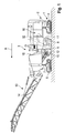
- Fig. 1 shows a side view of a road milling machine as an example of a milling machine in a simplified schematic representation.
- the milling machine can also be a recycler, stabilizer or surface miner.
- the milling machine has a machine frame 2 carried by a chassis 1 with an operator's platform 3.
- the chassis 1 of the milling machine can comprise four drives 4, 5, which are arranged on the rear and front on both sides of the machine frame 2.
- the steerable drives 4, 5, in particular chain drives, which allow translational and / or rotary movements of the milling machine, are attached to lifting cylinders 6, 7 which are attached to the machine frame 1 so that the machine frame is adjustable in height.
- the drives 4, 5 can be chain drives. Instead of chain drives, wheels can also be provided.
- the milling machine has a drive machine 16, in particular an internal combustion engine, arranged on the machine frame.
- the drive power of the internal combustion engine is transmitted to hydraulic pumps via a pump transfer gear in order to supply hydraulic motors provided in the drives 4, 5 of the milling machine with hydraulic fluid.
- the milling machine has a milling / cutting drum 8 which is arranged in a milling drum housing 9.
- the milling drum 8 is driven by the single drive machine, the drive power of the drive machine 16 being transmitted to the milling / cutting drum 8 via a mechanical gear 32.
- a device, not shown, for supplying water into the milling drum housing is provided, which has a pump device, not shown.
- the individual assemblies can in turn comprise several different components, for example actuators, sensors, etc., which, however, are also not shown since they are generally known to the person skilled in the art.
- a conveyor device 13 with a conveyor belt 14 is provided for transporting away the material removed by the milling / cutting drum.
- the machine operator can enter various operating parameters with an operating unit 15, which can be provided on the operator's platform 3.
- an operating unit 15 can be provided on the operator's platform 3.
- the relevant components of the individual assemblies are controlled with a central control and computing unit. However, several individual control and computing units can also be provided.
- the control and computing unit can, for example, be a general processor, a digital signal processor (DSP) for continuous processing of digital signals, a microprocessor, an application-specific integrated circuit (ASIC), an integrated circuit (FPGA) consisting of logic elements or other integrated circuits (IC) or have hardware components in order to carry out the individual method steps.
- DSP digital signal processor
- ASIC application-specific integrated circuit
- FPGA integrated circuit
- a data processing program software can run on the hardware components to carry out the method steps.
- a plurality or combination of the various components is also possible.
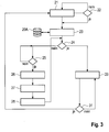
- Fig. 2 shows a simplified block diagram with the essential components of the milling machine.
- the drive device comprises the drive machine 16 and the drives, not shown, each having a hydraulic motor.
- the working device comprises, as a common component with the drive device, the milling / cutting roller 8, the hold-down device 10 arranged in front of the milling / cutting roller in the working direction, the scraper 11 behind the milling / cutting roller and the edge protection 12 on both sides of the Milling / cutting drum.
- Another assembly of the working device is the device 18 for adjusting the height of the machine frame 1, which has the four lifting columns 6, 7 so that the milling depth can be adjusted.
- the working device has the device 19 for supplying water with the pumping device and the conveying device 13 with the conveyor belt 14. The individual assemblies are connected to the central control and computing unit 20 via control lines 33.
- the speed of the drive machine 16 determines the speed n of the milling / cutting roller 8, which is driven by the drive machine via the mechanical transmission 32, while the feed speed v is set by setting the hydraulic pumps for the hydraulic motors accordingly.
- the operating unit 15 has an input unit 15A which, for example, can have buttons, switches, sliders, a keyboard or a touch screen in order to be able to enter certain parameters manually.
- the input unit 15A can also have a joystick for controlling the machine, in particular the steerable drives.
- the operating unit has a display unit 15B, for example a screen.
- micro-milling I micro-milling II, fine milling I, fine milling II, standard milling I, standard milling II, standard milling III, rough milling (rough milling), whereby different milling tasks can be selected for the individual milling types.
- the individual milling tasks are identified with the index "I", "II” or "III”.
- the milling tasks can be different milling patterns, which can differ in the roughness of the surface.
- Different framework conditions can also be taken into account, for example the type of subsoil (concrete or asphalt), or whether the soil should be processed as quickly as possible or with little wear.
- a data record is assigned to each operating mode and is stored in a memory 20A of the control and computing unit 20.
- Each data record contains the drive and work parameters that are considered optimal for the respective task.
- the data record does not have to contain all of the parameters that need to be set in order to complete the task.
- the data record also cannot contain individual operating parameters, in particular those parameters that should be able to be changed by the machine operator during operation of the milling machine. These parameters can be entered manually by the machine operator using the control unit.
- the machine operator selects an operating mode M 1 to M n with the selection unit 15C, for example by turning a rotary switch on the operating unit 15, for example the operating mode "Fine milling I" (block 21: "Selection of an operating mode”).
- the present exemplary embodiment provides an additional test routine.
- the milling / cutting roller used is identified by an identifier, for example a barcode, which is read out by a reader (not shown).
- the data set that corresponds to the operating mode "Fine milling I" is assigned, contains a list of identifications of different milling / cutting drums with which the milling task can be carried out, for example milling drum types for fine milling.
- the control and computing unit 20 checks whether the identification of the milling / cutting roller used is entered in the list (block 22: “Compatibility with roller?”). If this is the case, it is concluded that the milling machine is equipped with the correct milling drum type for "fine milling I". Thereupon the drive and working parameters are read out of the memory 20A, which are assigned to the operating mode “fine milling I” (block 23: “reading out operating parameters”). At this point in time, the machine is not yet in operation, ie the machine is at a standstill and the milling / cutting roller is not lowered (block 24: “Machine in operation?).
- the next step is to ask whether the milling operation should be started (block 25: "Start milling operation?). If this is the case, the The drive and work parameters required for starting the milling operation are based on the further control (block 26: “Setting the operating parameters for starting the machine”).
- one of the operating parameters for setting the milling machine is a speed n A for the drive machine is specified, which is, for example, 1600 1 / min, so that sufficient power is available for the attachment.
- the milling depth is not specified as a working parameter for the attachment, since the milling / cutting roller 8 is actuated by the machine operator by actuating the lifting columns 5, 6 is lowered manually to the desired depth (block 27: “Lowering to milling depth") lowering the milling / cutting roller 8, ie setting the milling depth, the machine operator sets the drives 4, 5 in motion (block 28: “Start up”). The milling machine is thus put into operation (block 24: “Milling machine in operation?”).
- the individual subassemblies of the milling machine are controlled by the control and computing unit 20 in such a way that the subassemblies carry out the respective machine functions on the basis of the drive and work parameters of the "Fine milling I" operating mode (block 29: “Setting the operating parameters for Milling mode ").
- the method steps carried out taking into account the selected operating mode are described in detail with reference to block 29.
- the control and computing unit 20 sets, for example, the motor speed n as an operating parameter, which can be a different speed than when the milling / cutting drum is applied.
- This motor speed n can also be contained in the data record "Precision Milling I" as a fixed, predetermined variable.
- the data record "Fine milling II” can differ from the data record "Fine milling I” in that the working parameter of the engine speed n for "Fine milling II" is greater or smaller than the working parameter of the engine speed n for "Fine milling I".
- the engine speed as an example of a working parameter, u. a. influences the milling drum speed, which determines the quality of the milling pattern.
- fine milling II is an operating mode with a finer milling pattern, i. H. a surface with a lower roughness should be, the required milling drum speed and thus the required motor speed n for "fine milling II” is greater than for "fine milling I".
- the milling pattern is also determined by the feed speed v of the milling machine, which the machine operator can change while the machine is in operation.
- a higher feed speed v requires a higher milling drum speed and thus a higher motor speed n.
- the feed speed v and the motor speed n are therefore related.
- a fixed value is therefore not specified for the motor speed n, but a value that is dependent on the feed rate v.
- different functions are stored in the memory 20A of the control and computing unit 20, which functions can differ from one another, for example in the constant k.
- the relationship between the feed rate v and the engine speed n can also be a non-linear relationship.
- the engine speed is particularly preferably regulated in discrete steps. For example, engine speeds of 1200 min -1 , 1600 min -1 , 1800 min -1 and 2100 min -1 can be provided for the milling operation. In this case, it is particularly preferable to keep the ratio v / n between feed and motor speed in a certain range.
- the motor speed can be adjusted when the limit values for the feed rate are exceeded or not reached.
- different functions can therefore be stored in the memory 20A of the control and arithmetic unit 20, which differ, for example, in the predefined areas in which the ratio between the feed rate and the motor speed should vary.
- the computing and evaluation unit uses the function stored for "Fine milling I" to calculate the required motor speed n, which can be a different speed for "Fine milling I” than, for example, for the "Fine milling" operating mode II “or” rough milling ".
- the control and computing unit 20 continuously monitors which feed rate the machine operator has specified. If the machine operator has changed the feed rate, the control and arithmetic unit 20 calculates the new motor speed with the function stored for the selected operating mode and then sets the new motor speed (block 29: "Setting the operating parameters for milling operation").
- the function can also be used to calculate and set the feed speed v after specifying a motor speed n.
- a drive parameter can determine a working parameter when controlling the individual assemblies, or vice versa.
- the working parameters for controlling the other assemblies of the working device are read out for the milling operation in order to control actuators or other drive devices of these assemblies.
- These parameters include in particular the height h of the hold-down device 10, scraper 11 and edge protection 12 or their bearing force on the floor.
- the height of the hold-down 10, stripper 11 and edge protection 12 is particularly dependent on the height of the machine frame 1 in relation to the surface of the floor, which in turn determines the milling depth.
- the control and arithmetic unit 20 sets the hold-down device 10, the stripper 11 and the edge protection 12 to the height or the bearing force predetermined by the parameters.
- the control and computing unit 20 also controls the pumping device of the device 19 for supplying water into the milling drum housing 9 in such a way that the amount of water is supplied that is specified by the corresponding working parameter for the "Fine milling 1" operating mode.
- This amount of water can be smaller than the amount of water that is specified by the corresponding working parameter for standard milling machines I, II, III, which in turn can be smaller than the amount of water for rough milling.
- control and computing unit 20 can also control the conveying device 13 present in milling machines, since, for example, the "fine milling" operating mode requires the setting of a smaller conveying quantity than "coarse milling".
- the above-mentioned operating parameters can not only be fixedly predefined sizes, but also sizes that are dependent on other operating parameters, as is the case, for example, for the speed of the milling / cutting roller.
- the modules described above can therefore also be controlled on the basis of the function describing the dependency of an operating parameter of a module on at least one operating parameter of at least one other module, which function is stored in the memory for the operating mode selected with the selection unit. For the start of the milling operation, depending on the operating mode, a predetermined value can first be set and then changed during the milling operation depending on at least one operating parameter.
- the operating parameters mentioned above can also depend on several other operating parameters.
- the engine speed n can be regulated not only as a function of the feed rate v, but also as a function of the power requirement of the consumers driven by the drive unit. Consequently, different specifications can be made for the various operating modes.
- the motor speed can be a function dependent on the feed, in which a specific minimum motor speed is functionally assigned to a specific feed speed, for example 1600 min -1 at a feed of 15 m / min.
- a specific minimum motor speed is functionally assigned to a specific feed speed, for example 1600 min -1 at a feed of 15 m / min.
- the motor speed is increased independently of the feed rate. If the feed rate is then increased, this can lead to a further increase in the motor speed depending on the functional relationship mentioned above, if the minimum motor speed determined as a function of the feed rate is above the currently set motor speed.
- the setting of the delivery rate of the pumping device of the device 19 for supplying water into the milling drum housing 9 can, for example, be based on a predetermined function that is stored in the memory 20C and is read out of the memory for the selected operating mode, depending on at least one Operating parameters of an assembly or several assemblies can be set.
- the function can describe the dependency of the delivery rate on the feed rate (drive parameters) and the milling depth (working parameters), whereby the delivery rate should increase with increasing feed rate and should also increase with increasing milling depth.
- the previously specified and set operating parameters are continuously monitored, with the control and computing unit 20 continuously checking whether the operating parameters previously read out from the memory 20A, on the basis of which the control is currently taking place, have been changed (block 31: "Modification Operating parameters? "). If the parameters have been changed, the new parameter sets are queried. If this is not the case, control of the machine continues on the basis of the previous parameters.
Landscapes
- Engineering & Computer Science (AREA)
- Mining & Mineral Resources (AREA)
- Mechanical Engineering (AREA)
- Architecture (AREA)
- Civil Engineering (AREA)
- Structural Engineering (AREA)
- Life Sciences & Earth Sciences (AREA)
- General Life Sciences & Earth Sciences (AREA)
- Geochemistry & Mineralogy (AREA)
- Geology (AREA)
- Road Repair (AREA)
- Numerical Control (AREA)
Claims (13)
- Fraiseuse, en particulier fraiseuse de route, stabilisateur, recycleuse ou mineuse de surface, avec
un dispositif d'entraînement qui est réalisé de telle manière que la fraiseuse réalise sur le sol des mouvements de translation et/ou de rotation, et un dispositif de travail qui est réalisé de telle manière que le sol soit usiné, dans laquelle la fraiseuse présente au moins deux modules (4, 5, 8, 10, 11, 12, 13, 18, 19) qui réalisent des fonctions de machine déterminées en fonction de paramètres de fonctionnement,
dans laquelle le dispositif d'entraînement comporte au moins un des au moins deux modules et dans laquelle le dispositif de travail comporte au moins un des au moins deux modules,
une unité de commande et de calcul (20) qui est configurée de telle manière que les au moins deux modules (4, 5, 8, 10, 11, 12, 13, 18, 19) de la fraiseuse soient commandés de telle manière qu'une fonction de machine déterminée soit réalisée, et
une unité de commande (15) pour l'entrée de paramètres de fonctionnement pour la commande du dispositif d'entraînement et du dispositif de travail,
caractérisée en ce que
l'unité de commande (15) présente une unité de sélection (15C) pour la sélection d'un mode de fonctionnement dans lequel l'au moins un module du dispositif de travail est en fonctionnement, à partir d'une pluralité de modes de fonctionnement, dans laquelle au moins deux paramètres de fonctionnement prédéfinis sont affectés à chaque mode de fonctionnement de la pluralité de modes de fonctionnement et/ou au moins une fonction décrivant la dépendance d'un paramètre de fonctionnement d'un module d'au moins un paramètre de fonctionnement d'au moins un autre module est affectée pour chaque mode de fonctionnement de la pluralité de modes de fonctionnement, et
l'unité de commande et de calcul (20) présente une mémoire (20A),
dans laquelle au moins deux paramètres de fonctionnement prédéfinis qui sont affectés au mode de fonctionnement sont enregistrés pour chaque mode de fonctionnement de la pluralité de modes de fonctionnement, et/ou
dans laquelle au moins une fonction décrivant la dépendance d'un paramètre de fonctionnement d'un module d'au moins un paramètre de fonctionnement d'au moins un autre module est enregistrée pour chaque mode de fonctionnement de la pluralité de modes de fonctionnement,
dans laquelle l'unité de commande et de calcul (20) est configurée de telle manière
qu'au moins un module (4, 5, 8, 10, 11, 12, 13, 18, 19) soit commandé en fonction des au moins deux paramètres de fonctionnement qui sont enregistrés pour le mode de fonctionnement sélectionné avec l'unité de sélection (15C) dans la mémoire (20A), de telle manière que la fonction de machine respective soit réalisée,
et/ou
que sur la base de la fonction décrivant la dépendance d'un paramètre de fonctionnement d'un module d'au moins un paramètre de fonctionnement d'au moins un autre module qui est enregistrée pour le mode de fonctionnement sélectionné avec l'unité de sélection (15C) dans la mémoire (20A), l'au moins un module (8, 10, 11, 12, 13, 17, 18, 19 ; 4, 5) soit commandé de telle manière que la fonction de machine respective soit réalisée, et
que les paramètres de fonctionnement comportent des paramètres d'entraînement et des paramètres de travail,
dans laquelle l'au moins un module (4 5) du dispositif d'entraînement réalise en fonction des paramètres d'entraînement une fonction de machine déterminée, et l'au moins un module (8, 10, 11, 12, 13, 18, 19) du dispositif de travail réalise en fonction des paramètres de travail une fonction de machine déterminée. - Fraiseuse selon la revendication 1, caractérisée en ce qu'un module du dispositif d'entraînement comporte des mécanismes de roulement (4, 5) entraînés de manière motorisée, sur lesquels l'engin se situe, dans laquelle un paramètre d'entraînement est la vitesse d'avance (v) de la fraiseuse, et un module du dispositif de travail comporte un rouleau de fraisage et de coupe (8) entraîné de manière motorisée, dans laquelle un paramètre de travail est la vitesse de rotation (n) du rouleau de fraisage et de coupe.
- Fraiseuse selon la revendication 2, caractérisée en ce que la vitesse d'avance (v) est un paramètre d'entraînement pouvant être entré avec l'unité de commande (15) pour la commande du dispositif d'entraînement.
- Fraiseuse selon l'une des revendications 1 à 3, caractérisée en ce que l'unité de commande et de calcul (20) est configurée de telle manière
qu'au moins deux paramètres de travail prescrits qui sont affectés au mode de fonctionnement soient enregistrés dans la mémoire (20A) pour chaque mode de fonctionnement de la pluralité des modes de fonctionnement sélectionnables avec l'unité de sélection (15C),
et/ou
et qu'au moins une fonction décrivant la dépendance d'un paramètre de travail d'un module d'au moins un paramètre d'entraînement d'au moins un autre module et/ou au moins une fonction décrivant la dépendance d'un paramètre d'entraînement d'un module d'au moins un paramètre de travail d'au moins un autre module est enregistrée pour chaque mode de fonctionnement de la pluralité des modes de fonctionnement sélectionnables avec l'unité de sélection (15C) dans la mémoire (20A),
dans laquelle l'unité de commande et de calcul (20) est configurée de telle manière
qu'au moins un module (8, 10, 11, 12, 13, 17, 18, 19) du dispositif de travail soit commandé en fonction des au moins deux paramètres de travail qui sont enregistrés pour le mode de fonctionnement sélectionné avec l'unité de sélection (15C) dans la mémoire (20A) de telle manière que la fonction de machine respective soit réalisée, et/ou
que sur la base de la fonction décrivant la dépendance d'un paramètre de travail d'un module d'au moins un paramètre d'entraînement d'au moins un autre module ou sur la base de la fonction décrivant la dépendance d'un paramètre d'entraînement d'un module d'au moins un paramètre de travail d'au moins un autre module qui est enregistrée pour le mode de fonctionnement sélectionné avec l'unité de sélection (15C) dans la mémoire (20A), au moins un module (8, 10, 11, 12, 13, 18, 19 ; 4, 5) du dispositif de travail ou dispositif d'entraînement soit commandé de telle manière que la fonction de machine respective soit réalisée. - Fraiseuse selon l'une des revendications 2 à 4, caractérisée en ce qu'une fonction décrivant la dépendance d'un paramètre de travail d'un module d'un paramètre d'entraînement d'un autre module est une fonction décrivant la dépendance de la vitesse de rotation (n) du rouleau de fraisage et de coupe (8) de la vitesse d'avance (v) de la fraiseuse, dans laquelle l'unité de commande et de calcul (20) est configurée de telle manière que sur la base de la fonction décrivant la dépendance de la vitesse de rotation du rouleau de fraisage et de coupe de la vitesse d'avance de la fraiseuse qui est enregistrée pour le mode de fonctionnement sélectionné avec l'unité de sélection (15C) dans la mémoire (20A), la vitesse de rotation (n) du rouleau de fraisage et de coupe (8) est réglée pour une vitesse d'avance (v) prédéfinie.
- Fraiseuse selon l'une des revendications 2 à 5, caractérisée en ce qu'une fonction est enregistrée pour un premier mode de fonctionnement de la pluralité de modes de fonctionnement sélectionnables avec l'unité de sélection (15C) dans la mémoire (20A), laquelle prédéfinit pour une vitesse d'avance (v) prédéfinie une vitesse de rotation (n) plus grande du rouleau de fraisage et de coupe (8) que pour un second mode de fonctionnement de la pluralité de modes de fonctionnement.
- Fraiseuse selon l'une des revendications 2 à 6, caractérisée en ce qu'un module de la fraiseuse comporte un dispositif (19) pour l'amenée d'eau dans un boîtier de rouleau de fraisage et de coupe (9) recevant le rouleau de fraisage et de coupe (8) avec un dispositif de pompage entraîné de manière motorisée, dans laquelle un paramètre de travail est la quantité de transport du dispositif de pompage.
- Fraiseuse selon la revendication 7, caractérisée en ce qu'une fonction est enregistrée pour un premier mode de fonctionnement de la pluralité de modes de fonctionnement sélectionnables avec l'unité de sélection (15C) dans la mémoire (20A), laquelle prédéfinit pour une vitesse d'avance (v) prédéfinie une plus grande quantité de transport du dispositif de pompage que pour un second mode de fonctionnement de la pluralité de modes de fonctionnement.
- Fraiseuse selon l'une des revendications 2 à 8, caractérisée en ce qu'un module du dispositif de travail comporte un dispositif de transport (13) entraîné de manière motorisée pour le transport de matériau enlevé avec le rouleau de fraisage et de coupe (8), dans laquelle un paramètre de travail est la quantité de transport du dispositif de transport.
- Fraiseuse selon la revendication 9, caractérisée en ce qu'une fonction est enregistrée pour un premier mode de fonctionnement de la pluralité de modes de fonctionnement sélectionnables avec l'unité de sélection (15C) dans la mémoire (20A), laquelle prédéfinit pour une vitesse d'avance (v) prédéfinie une plus grande quantité de transport du dispositif de transport que pour un second mode de fonctionnement de la pluralité de modes de fonctionnement.
- Fraiseuse selon l'une des revendications 2 à 10, caractérisée en ce qu'un module du dispositif de travail comporte un élément de retenue (10) réglable en hauteur par rapport au sol et reposant avec une force d'appui prescrite sur le sol, qui est agencé dans le sens de travail de la fraiseuse devant le rouleau de fraisage et de coupe (8), ou un racleur (11) réglable en hauteur par rapport au sol et reposant avec une force d'appui prescrite sur le sol, qui est agencé dans le sens de travail de la fraiseuse derrière le rouleau de coupe et de fraisage, ou une protection d'arête (12) réglable en hauteur par rapport au sol et reposant avec une force d'appui prescrite sur le sol, qui est agencée dans le sens longitudinal de la fraiseuse, dans laquelle un paramètre de travail est le réglage en hauteur ou la force d'appui de l'élément de retenue ou du racleur ou de la protection d'arête.
- Procédé de fonctionnement d'une fraiseuse, en particulier fraiseuse sur route, stabilisateur, recycleuse ou mineuse de surface, avec un dispositif d'entraînement pour la réalisation de mouvements de translation et/ou de rotation, et un dispositif de travail pour l'usinage du sol, dans lequel la fraiseuse présente au moins deux modules qui réalisent des fonctions de machine déterminées en fonction de paramètres de fonctionnement,
dans lequel le dispositif d'entraînement comporte au moins un des au moins deux modules et dans lequel le dispositif de travail comporte au moins un des au moins deux modules,
avec les étapes de procédé suivantes :la prévoyance d'une pluralité de modes de fonctionnement pour la sélection d'un mode de fonctionnement, dans lequel l'au moins un module du dispositif de travail est en fonctionnement, à partir de la pluralité de modes de fonctionnement,dans lequel au moins deux paramètres de fonctionnement prédéfinis sont affectés à chaque mode de fonctionnement de la pluralité de modes de fonctionnement et/ou pour chaque mode de fonctionnement de la pluralité de modes de fonctionnement au moins une fonction décrivant la dépendance d'un paramètre de fonctionnement d'un module d'au moins un paramètre de fonctionnement d'au moins un autre module est affectée,l'enregistrement dans une mémoire pour chaque mode de fonctionnement de la pluralité de modes de fonctionnement d'au moins deux paramètres de fonctionnement prédéfinis qui sont affectés au mode de fonctionnement, et/ou l'enregistrement dans une mémoire pour chaque mode de fonctionnement de la pluralité de modes de fonctionnement d'au moins une fonction décrivant la dépendance d'un paramètre de fonctionnement d'un module d'au moins un paramètre de fonctionnement d'au moins un autre module,la sélection d'un mode de fonctionnement à partir de la pluralité de modes de fonctionnement,la commande d'au moins un module en fonction des au moins deux paramètres de fonctionnement, qui sont enregistrés pour le mode de fonctionnement sélectionné dans la mémoire de sorte que la fonction de machine respective soit réalisée, et/oula commande d'au moins un module sur la base de la fonction décrivant la dépendance d'un paramètre de fonctionnement du module d'un paramètre de fonctionnement d'un autre module qui est enregistrée pour le mode de fonctionnement sélectionné dans la mémoire de sorte que l'au moins un module réalise la fonction de machine respective, dans lequelles paramètres de fonctionnement comportent des paramètres d'entraînement et des paramètres de travail, dans lequel l'au moins un module du dispositif d'entraînement réalise en fonction de paramètres d'entraînement une fonction de machine déterminée, et l'au moins un module du dispositif de travail réalise en fonction de paramètres de travail une fonction de machine déterminée. - Procédé selon la revendication 12, caractérisé en ce que le procédé présente les étapes de procédé suivantes :l'enregistrement dans la mémoire pour chaque mode de fonctionnement d'une pluralité de modes de fonctionnement sélectionnables d'au moins deux paramètres de travail prédéfinis qui sont affectés au mode de fonctionnement,la commande d'au moins un module du dispositif de travail en fonction des au moins deux paramètres de travail qui sont enregistrés pour le mode de fonctionnement sélectionné dans la mémoire de sorte que la fonction de machine respective soit réalisée, et/oula commande d'au moins un module du dispositif de travail ou dispositif d'entraînement sur la base de la fonction décrivant la dépendance d'un paramètre de travail d'un module d'au moins un paramètre d'entraînement d'un autre module ou sur la base de la fonction décrivant la dépendance d'un paramètre d'entraînement d'un module d'au moins un paramètre de travail d'un autre module qui est enregistrée pour le mode de fonctionnement sélectionné dans la mémoire de sorte que la fonction de machine respective soit réalisée.
Applications Claiming Priority (1)
| Application Number | Priority Date | Filing Date | Title |
|---|---|---|---|
| DE102016010390.6A DE102016010390A1 (de) | 2016-08-30 | 2016-08-30 | Fräsmaschine und Verfahren zum Betrieb einer Fräsmaschine |
Publications (2)
| Publication Number | Publication Date |
|---|---|
| EP3290586A1 EP3290586A1 (fr) | 2018-03-07 |
| EP3290586B1 true EP3290586B1 (fr) | 2020-10-14 |
Family
ID=59745707
Family Applications (1)
| Application Number | Title | Priority Date | Filing Date |
|---|---|---|---|
| EP17186317.8A Active EP3290586B1 (fr) | 2016-08-30 | 2017-08-15 | Fraiseuse et procédé de fonctionnement d'une fraiseuse |
Country Status (4)
| Country | Link |
|---|---|
| US (3) | US10378350B2 (fr) |
| EP (1) | EP3290586B1 (fr) |
| CN (1) | CN107780329B (fr) |
| DE (1) | DE102016010390A1 (fr) |
Families Citing this family (15)
| Publication number | Priority date | Publication date | Assignee | Title |
|---|---|---|---|---|
| DE102016113251A1 (de) * | 2015-10-27 | 2017-04-27 | Wirtgen Gmbh | Fräsmaschine und Verfahren zum Betrieb einer Fräsmaschine |
| DE102016010390A1 (de) * | 2016-08-30 | 2018-03-01 | Wirtgen Gmbh | Fräsmaschine und Verfahren zum Betrieb einer Fräsmaschine |
| US10309066B2 (en) * | 2016-11-04 | 2019-06-04 | Caterpillar Paving Products Inc. | Control system for cold planer and apparatus and method thereof |
| US10386866B2 (en) * | 2017-11-20 | 2019-08-20 | Caterpillar Paving Products Inc. | Automatic control of plunge velocity based on depth of cut |
| DE102017010919B4 (de) * | 2017-11-24 | 2023-08-03 | Bomag Gmbh | Verfahren zum Steuern einer Höhenverstellung eines Abstreifschildes einer Bodenfräsmaschine und Bodenfräsmaschine |
| US10733991B2 (en) * | 2017-12-21 | 2020-08-04 | Deere & Company | Construction machine mode switching with voice services |
| US10621982B2 (en) | 2017-12-21 | 2020-04-14 | Deere & Company | Construction machines with voice services |
| CN108677670A (zh) * | 2018-07-02 | 2018-10-19 | 江阴澄云机械有限公司 | 一种铣刨机 |
| CN111287059A (zh) * | 2020-02-19 | 2020-06-16 | 徐州徐工筑路机械有限公司 | 一种冷再生施工自动化系统 |
| DE102021114397A1 (de) * | 2021-06-03 | 2022-12-08 | Bomag Gmbh | Verfahren zur Steuerung einer Straßenfräsmaschine und Straßenfräsmaschine |
| CN113564992A (zh) * | 2021-08-13 | 2021-10-29 | 李维维 | 一种微表处摊铺机及施工方法 |
| CN113463477A (zh) * | 2021-08-13 | 2021-10-01 | 李维维 | 一种微表处摊铺机及施工方法 |
| CN113463469A (zh) * | 2021-08-13 | 2021-10-01 | 李维维 | 一种微表处摊铺机及施工方法 |
| DE102021133306A1 (de) * | 2021-12-15 | 2023-06-15 | Wirtgen Gmbh | Verfahren zur Aufwands-Abschätzung einer geplanten Fräsaufgabe, die mit einer Straßenfräsmaschine durchgeführt wird oder durchgeführt werden soll |
| DE102022122472B4 (de) * | 2022-09-05 | 2024-03-28 | Wirtgen Gmbh | Selbstfahrende Bodenbearbeitungsmaschine mit Zwillingsmotoren und einem deren Leistung unterschiedlich übertragenden Arbeitsgetriebe |
Citations (1)
| Publication number | Priority date | Publication date | Assignee | Title |
|---|---|---|---|---|
| US20100014917A1 (en) * | 2007-03-20 | 2010-01-21 | Willis Paul E | Milling machine with cutter drum speed control |
Family Cites Families (42)
| Publication number | Priority date | Publication date | Assignee | Title |
|---|---|---|---|---|
| US2311891A (en) | 1941-04-17 | 1943-02-23 | Tyson Harry | Road grooving machine |
| DE1917670C3 (de) | 1969-04-05 | 1973-01-04 | Eimer, Manfred, Dipl.Ing., Dr., 3400 Grone | Einrichtung zur selbsttätigen Regelung des Dreschprozesses bei einem Mähdrescher |
| US3750762A (en) | 1971-08-19 | 1973-08-07 | Omsteel Ind Inc | Speed control system for vehicle mounting a work performing device |
| US4043402A (en) | 1975-03-24 | 1977-08-23 | Koehring Company | Soil stabilizer machine with detachable hydraulic motor structure driving rotatably mounted cutting elements |
| US4549610A (en) | 1979-06-05 | 1985-10-29 | Lely Cornelis V D | Vehicle with front and rear steerable wheels individually driven by hydraulic motors |
| US4270801A (en) * | 1979-08-14 | 1981-06-02 | Cmi Corporation | Steering and cutter drum positioning in a paved roadway planing machine |
| US4277898A (en) | 1979-12-26 | 1981-07-14 | J. I. Case Company | Hydraulic control system for excavating machine |
| US4333685A (en) | 1980-06-09 | 1982-06-08 | Federal-Mogul Corporation | Road surfacing apparatus |
| US4343513A (en) | 1980-08-25 | 1982-08-10 | Gomaco, Inc. | Method and power transmission system for operating a road planar machine |
| US4588231A (en) | 1982-01-27 | 1986-05-13 | Concrete Safety Equipment, Inc. | Pavement surfacing machine |
| HU195345B (en) | 1984-02-24 | 1988-04-28 | Mem Mueszaki Intezet | Method and regulator for controlling load of machine and speed of a mobile straw cutter |
| US4655634A (en) | 1985-09-23 | 1987-04-07 | Dresser Industries, Inc. | Road planer control and safety system |
| IT1205549B (it) | 1986-07-11 | 1989-03-23 | Elda Barbieri | Macchina frantumatrice mobile semovente |
| US4929121A (en) * | 1989-09-05 | 1990-05-29 | Caterpillar Paving Products Inc. | Control system for a road planer |
| US5190398A (en) | 1991-03-12 | 1993-03-02 | Swisher Jr George W | Apparatus for preparing a road bed |
| US5318378A (en) | 1992-09-28 | 1994-06-07 | Caterpillar Paving Products Inc. | Method and apparatus for controlling a cold planer in response to a kickback event |
| US5415495A (en) | 1993-07-19 | 1995-05-16 | Surface Preparation Technologies, Inc. | Cutting machine and a method for its use |
| US6186248B1 (en) | 1995-12-12 | 2001-02-13 | Boart Longyear Company | Closed loop control system for diamond core drilling |
| US5879056A (en) | 1997-04-25 | 1999-03-09 | Caterpillar Inc. | Kickback protection device and method of use |
| US6050770A (en) | 1997-05-30 | 2000-04-18 | Schaeff Incorporated | Stabilization system for load handling equipment |
| US6338281B1 (en) | 1997-08-13 | 2002-01-15 | Reliance Electric Technologies, Llc | Bearing apparatus having integrated load sensing arrangement |
| GB9912108D0 (en) | 1999-05-25 | 1999-07-28 | Rolls Royce Plc | Bearing load control |
| US6558072B2 (en) | 2001-05-15 | 2003-05-06 | Caterpillar Paving Products Inc. | Speed control system for a work machine |
| DE10203732A1 (de) | 2002-01-30 | 2003-08-21 | Wirtgen Gmbh | Baumaschine |
| DE10213017A1 (de) | 2002-03-22 | 2003-10-09 | Wirtgen Gmbh | Verfahren zum Optimieren eines Schneidprozesses bei Straßenfräsmaschinen, sowie Fräsmaschine zum Bearbeiten von Straßendecken |
| US6921230B2 (en) | 2002-12-24 | 2005-07-26 | Diamond Products, Limited | Closed loop control system for pavement surfacing machine |
| US7066555B2 (en) * | 2003-08-26 | 2006-06-27 | Asphalt Zipper, Inc. | Reinforced concrete milling/cutting mandrel |
| DE102006024123B4 (de) | 2006-05-22 | 2010-02-25 | Wirtgen Gmbh | Selbstfahrende Baumaschine, sowie Verfahren zum Bearbeiten von Bodenoberflächen |
| US8465105B2 (en) | 2007-01-18 | 2013-06-18 | Cmi Terex Corporation | Control system for cutter drum |
| DE102008008260B4 (de) * | 2008-02-08 | 2010-09-09 | Wirtgen Gmbh | Steuerung einer Gewinnungsmaschine und Gewinnungsmaschine |
| US8128177B2 (en) | 2010-02-08 | 2012-03-06 | Wirtgen Gmbh | Adaptive advance drive control for milling machine |
| CN202838001U (zh) * | 2012-09-25 | 2013-03-27 | 三一重工股份有限公司 | 一种路面施工机群及其配合引导系统 |
| US8989968B2 (en) * | 2012-10-12 | 2015-03-24 | Wirtgen Gmbh | Self-propelled civil engineering machine system with field rover |
| DE102012020655A1 (de) * | 2012-10-19 | 2014-04-24 | Wirtgen Gmbh | Selbstfahrende Baumaschine |
| DE102013013967A1 (de) | 2013-08-23 | 2015-03-12 | Wirtgen Gmbh | Selbstfahrende Baumaschine und Verfahren zum Betreiben einer selbstfahrenden Baumaschine |
| WO2015042226A1 (fr) * | 2013-09-20 | 2015-03-26 | Surface Preparation Technologies Llc | Procédé et appareil pour découper une rainure sinusoïdale dans une surface routière |
| DE102014001885A1 (de) | 2014-02-12 | 2015-08-13 | Bomag Gmbh | Verfahren zur Optimierung einer Betriebsfunktion einer Bodenfräsmaschine und Bodenfräsmaschine |
| DE102015002743A1 (de) | 2014-12-23 | 2016-06-23 | Wirtgen Gmbh | Selbstfahrende Baumaschine und Verfahren zum Betreiben einer selbstfahrenden Baumaschine |
| DE102015002426A1 (de) | 2014-12-30 | 2016-06-30 | Bomag Gmbh | Bodenfräsmaschine und Verfahren zum Verstellen des Abstreiferschildes einer Bodenfräsmaschine |
| DE102016001720B4 (de) | 2016-02-16 | 2020-09-17 | Wirtgen Gmbh | Selbstfahrende Baumaschine und Verfahren zum Betreiben einer selbstfahrenden Baumaschine |
| US10094078B2 (en) * | 2016-03-03 | 2018-10-09 | Caterpillar Paving Products Inc. | Cold planer rear door and sliding plates sealing design |
| DE102016010390A1 (de) * | 2016-08-30 | 2018-03-01 | Wirtgen Gmbh | Fräsmaschine und Verfahren zum Betrieb einer Fräsmaschine |
-
2016
- 2016-08-30 DE DE102016010390.6A patent/DE102016010390A1/de active Pending
-
2017
- 2017-08-15 EP EP17186317.8A patent/EP3290586B1/fr active Active
- 2017-08-16 CN CN201710702628.XA patent/CN107780329B/zh active Active
- 2017-08-17 US US15/679,199 patent/US10378350B2/en active Active
-
2019
- 2019-08-08 US US16/535,407 patent/US11203929B2/en active Active
-
2021
- 2021-12-14 US US17/550,829 patent/US12312955B2/en active Active
Patent Citations (1)
| Publication number | Priority date | Publication date | Assignee | Title |
|---|---|---|---|---|
| US20100014917A1 (en) * | 2007-03-20 | 2010-01-21 | Willis Paul E | Milling machine with cutter drum speed control |
Also Published As
| Publication number | Publication date |
|---|---|
| CN107780329B (zh) | 2019-11-15 |
| US20200072049A1 (en) | 2020-03-05 |
| DE102016010390A1 (de) | 2018-03-01 |
| US10378350B2 (en) | 2019-08-13 |
| US11203929B2 (en) | 2021-12-21 |
| CN107780329A (zh) | 2018-03-09 |
| US20180058214A1 (en) | 2018-03-01 |
| EP3290586A1 (fr) | 2018-03-07 |
| US12312955B2 (en) | 2025-05-27 |
| US20220170367A1 (en) | 2022-06-02 |
Similar Documents
| Publication | Publication Date | Title |
|---|---|---|
| EP3290586B1 (fr) | Fraiseuse et procédé de fonctionnement d'une fraiseuse | |
| EP3483341B1 (fr) | Engin de chantier automoteur et procédé de fonctionnement d'un engin de chantier automoteur | |
| DE112008000646T5 (de) | Fräsmaschine mit Schneidtrommel-Geschwindigkeitssteuerung | |
| DE112013002969B4 (de) | Motordrehzahlmanagement-Steuersystem für Kaltfräsen | |
| DE102010015173B4 (de) | Verfahren zum Betrieb einer Bodenfräsmaschine mit höhenverstellbarer Fräswalze | |
| DE112015003533T5 (de) | Kaltfräse mit unabhängig gesteuerten Fördereinrichtungen | |
| DE102012221654A1 (de) | Verfahren zum Behandeln von Schichten, sowie eine Baumaschine, insbesondere einen Bodenstabilisierer oder Recycler | |
| EP2722441A1 (fr) | Engin automoteur et procédé de fonctionnement d'un engin automoteur | |
| DE102017110146A1 (de) | Fräsmaschine | |
| DE102021108487A1 (de) | Maschine, system und verfahren zur automatisierung des arbeitszyklus | |
| DE102019108759B4 (de) | Bodenbearbeitungsmaschine | |
| EP3415690B1 (fr) | Fraiseuse et procédé de fonctionnement d'une fraiseuse | |
| EP0344548A3 (fr) | Méthode et appareillage pour le contrôle fu fonctionnement de machines à rôder ou rectifier | |
| EP3587668B1 (fr) | Engin de construction automoteur et procédé de traitement des revêtements de sol | |
| DE102016001720B4 (de) | Selbstfahrende Baumaschine und Verfahren zum Betreiben einer selbstfahrenden Baumaschine | |
| DE112009004293T5 (de) | Adaptive Unterdrehzahlsteuerung | |
| DE112021007705T5 (de) | Werkzeugmaschinensteuerungsvorrichtung und Werkzeugmaschinensteuerungssystem | |
| DE102019104478A1 (de) | Materialtransportsystem | |
| EP3585520B1 (fr) | Installation automotrice pour traiter et/ou transborder des matériaux | |
| WO2024208738A1 (fr) | Système de transport pour des pièces à travailler et procédé permettant de faire fonctionner un système de transport | |
| DE102017004327A1 (de) | Systeme und Verfahren für eine Fluidzufuhr in einem Langfrontabbausystem | |
| DE19811316A1 (de) | Lageregelung für eine Kombinationsfräsmaschine mit innen angeordneter Schleifscheibe | |
| DE102023128579A1 (de) | Bodenverdichtungssystem mit Künstlicher Intelligenz | |
| DE102022126170A1 (de) | System und verfahren zur materialentleerung in fräskammer | |
| DE102022134946A1 (de) | Verdichtungsmusteranpassungen für die automatische verdichtung |
Legal Events
| Date | Code | Title | Description |
|---|---|---|---|
| PUAI | Public reference made under article 153(3) epc to a published international application that has entered the european phase |
Free format text: ORIGINAL CODE: 0009012 |
|
| STAA | Information on the status of an ep patent application or granted ep patent |
Free format text: STATUS: THE APPLICATION HAS BEEN PUBLISHED |
|
| AK | Designated contracting states |
Kind code of ref document: A1 Designated state(s): AL AT BE BG CH CY CZ DE DK EE ES FI FR GB GR HR HU IE IS IT LI LT LU LV MC MK MT NL NO PL PT RO RS SE SI SK SM TR |
|
| AX | Request for extension of the european patent |
Extension state: BA ME |
|
| STAA | Information on the status of an ep patent application or granted ep patent |
Free format text: STATUS: REQUEST FOR EXAMINATION WAS MADE |
|
| 17P | Request for examination filed |
Effective date: 20180905 |
|
| RBV | Designated contracting states (corrected) |
Designated state(s): AL AT BE BG CH CY CZ DE DK EE ES FI FR GB GR HR HU IE IS IT LI LT LU LV MC MK MT NL NO PL PT RO RS SE SI SK SM TR |
|
| STAA | Information on the status of an ep patent application or granted ep patent |
Free format text: STATUS: EXAMINATION IS IN PROGRESS |
|
| 17Q | First examination report despatched |
Effective date: 20190718 |
|
| GRAP | Despatch of communication of intention to grant a patent |
Free format text: ORIGINAL CODE: EPIDOSNIGR1 |
|
| STAA | Information on the status of an ep patent application or granted ep patent |
Free format text: STATUS: GRANT OF PATENT IS INTENDED |
|
| INTG | Intention to grant announced |
Effective date: 20200424 |
|
| GRAS | Grant fee paid |
Free format text: ORIGINAL CODE: EPIDOSNIGR3 |
|
| GRAA | (expected) grant |
Free format text: ORIGINAL CODE: 0009210 |
|
| STAA | Information on the status of an ep patent application or granted ep patent |
Free format text: STATUS: THE PATENT HAS BEEN GRANTED |
|
| AK | Designated contracting states |
Kind code of ref document: B1 Designated state(s): AL AT BE BG CH CY CZ DE DK EE ES FI FR GB GR HR HU IE IS IT LI LT LU LV MC MK MT NL NO PL PT RO RS SE SI SK SM TR |
|
| REG | Reference to a national code |
Ref country code: GB Ref legal event code: FG4D Free format text: NOT ENGLISH |
|
| REG | Reference to a national code |
Ref country code: AT Ref legal event code: REF Ref document number: 1323687 Country of ref document: AT Kind code of ref document: T Effective date: 20201015 Ref country code: CH Ref legal event code: EP |
|
| REG | Reference to a national code |
Ref country code: DE Ref legal event code: R096 Ref document number: 502017007721 Country of ref document: DE |
|
| REG | Reference to a national code |
Ref country code: IE Ref legal event code: FG4D Free format text: LANGUAGE OF EP DOCUMENT: GERMAN |
|
| REG | Reference to a national code |
Ref country code: NL Ref legal event code: MP Effective date: 20201014 |
|
| PG25 | Lapsed in a contracting state [announced via postgrant information from national office to epo] |
Ref country code: GR Free format text: LAPSE BECAUSE OF FAILURE TO SUBMIT A TRANSLATION OF THE DESCRIPTION OR TO PAY THE FEE WITHIN THE PRESCRIBED TIME-LIMIT Effective date: 20210115 Ref country code: FI Free format text: LAPSE BECAUSE OF FAILURE TO SUBMIT A TRANSLATION OF THE DESCRIPTION OR TO PAY THE FEE WITHIN THE PRESCRIBED TIME-LIMIT Effective date: 20201014 Ref country code: NO Free format text: LAPSE BECAUSE OF FAILURE TO SUBMIT A TRANSLATION OF THE DESCRIPTION OR TO PAY THE FEE WITHIN THE PRESCRIBED TIME-LIMIT Effective date: 20210114 Ref country code: NL Free format text: LAPSE BECAUSE OF FAILURE TO SUBMIT A TRANSLATION OF THE DESCRIPTION OR TO PAY THE FEE WITHIN THE PRESCRIBED TIME-LIMIT Effective date: 20201014 Ref country code: RS Free format text: LAPSE BECAUSE OF FAILURE TO SUBMIT A TRANSLATION OF THE DESCRIPTION OR TO PAY THE FEE WITHIN THE PRESCRIBED TIME-LIMIT Effective date: 20201014 Ref country code: PT Free format text: LAPSE BECAUSE OF FAILURE TO SUBMIT A TRANSLATION OF THE DESCRIPTION OR TO PAY THE FEE WITHIN THE PRESCRIBED TIME-LIMIT Effective date: 20210215 |
|
| REG | Reference to a national code |
Ref country code: LT Ref legal event code: MG4D |
|
| PG25 | Lapsed in a contracting state [announced via postgrant information from national office to epo] |
Ref country code: SE Free format text: LAPSE BECAUSE OF FAILURE TO SUBMIT A TRANSLATION OF THE DESCRIPTION OR TO PAY THE FEE WITHIN THE PRESCRIBED TIME-LIMIT Effective date: 20201014 Ref country code: BG Free format text: LAPSE BECAUSE OF FAILURE TO SUBMIT A TRANSLATION OF THE DESCRIPTION OR TO PAY THE FEE WITHIN THE PRESCRIBED TIME-LIMIT Effective date: 20210114 Ref country code: LV Free format text: LAPSE BECAUSE OF FAILURE TO SUBMIT A TRANSLATION OF THE DESCRIPTION OR TO PAY THE FEE WITHIN THE PRESCRIBED TIME-LIMIT Effective date: 20201014 Ref country code: IS Free format text: LAPSE BECAUSE OF FAILURE TO SUBMIT A TRANSLATION OF THE DESCRIPTION OR TO PAY THE FEE WITHIN THE PRESCRIBED TIME-LIMIT Effective date: 20210214 Ref country code: PL Free format text: LAPSE BECAUSE OF FAILURE TO SUBMIT A TRANSLATION OF THE DESCRIPTION OR TO PAY THE FEE WITHIN THE PRESCRIBED TIME-LIMIT Effective date: 20201014 Ref country code: ES Free format text: LAPSE BECAUSE OF FAILURE TO SUBMIT A TRANSLATION OF THE DESCRIPTION OR TO PAY THE FEE WITHIN THE PRESCRIBED TIME-LIMIT Effective date: 20201014 |
|
| PG25 | Lapsed in a contracting state [announced via postgrant information from national office to epo] |
Ref country code: HR Free format text: LAPSE BECAUSE OF FAILURE TO SUBMIT A TRANSLATION OF THE DESCRIPTION OR TO PAY THE FEE WITHIN THE PRESCRIBED TIME-LIMIT Effective date: 20201014 |
|
| REG | Reference to a national code |
Ref country code: DE Ref legal event code: R097 Ref document number: 502017007721 Country of ref document: DE |
|
| PG25 | Lapsed in a contracting state [announced via postgrant information from national office to epo] |
Ref country code: RO Free format text: LAPSE BECAUSE OF FAILURE TO SUBMIT A TRANSLATION OF THE DESCRIPTION OR TO PAY THE FEE WITHIN THE PRESCRIBED TIME-LIMIT Effective date: 20201014 Ref country code: SK Free format text: LAPSE BECAUSE OF FAILURE TO SUBMIT A TRANSLATION OF THE DESCRIPTION OR TO PAY THE FEE WITHIN THE PRESCRIBED TIME-LIMIT Effective date: 20201014 Ref country code: SM Free format text: LAPSE BECAUSE OF FAILURE TO SUBMIT A TRANSLATION OF THE DESCRIPTION OR TO PAY THE FEE WITHIN THE PRESCRIBED TIME-LIMIT Effective date: 20201014 Ref country code: LT Free format text: LAPSE BECAUSE OF FAILURE TO SUBMIT A TRANSLATION OF THE DESCRIPTION OR TO PAY THE FEE WITHIN THE PRESCRIBED TIME-LIMIT Effective date: 20201014 Ref country code: EE Free format text: LAPSE BECAUSE OF FAILURE TO SUBMIT A TRANSLATION OF THE DESCRIPTION OR TO PAY THE FEE WITHIN THE PRESCRIBED TIME-LIMIT Effective date: 20201014 Ref country code: CZ Free format text: LAPSE BECAUSE OF FAILURE TO SUBMIT A TRANSLATION OF THE DESCRIPTION OR TO PAY THE FEE WITHIN THE PRESCRIBED TIME-LIMIT Effective date: 20201014 |
|
| PLBE | No opposition filed within time limit |
Free format text: ORIGINAL CODE: 0009261 |
|
| STAA | Information on the status of an ep patent application or granted ep patent |
Free format text: STATUS: NO OPPOSITION FILED WITHIN TIME LIMIT |
|
| PG25 | Lapsed in a contracting state [announced via postgrant information from national office to epo] |
Ref country code: DK Free format text: LAPSE BECAUSE OF FAILURE TO SUBMIT A TRANSLATION OF THE DESCRIPTION OR TO PAY THE FEE WITHIN THE PRESCRIBED TIME-LIMIT Effective date: 20201014 |
|
| 26N | No opposition filed |
Effective date: 20210715 |
|
| PG25 | Lapsed in a contracting state [announced via postgrant information from national office to epo] |
Ref country code: AL Free format text: LAPSE BECAUSE OF FAILURE TO SUBMIT A TRANSLATION OF THE DESCRIPTION OR TO PAY THE FEE WITHIN THE PRESCRIBED TIME-LIMIT Effective date: 20201014 |
|
| PG25 | Lapsed in a contracting state [announced via postgrant information from national office to epo] |
Ref country code: SI Free format text: LAPSE BECAUSE OF FAILURE TO SUBMIT A TRANSLATION OF THE DESCRIPTION OR TO PAY THE FEE WITHIN THE PRESCRIBED TIME-LIMIT Effective date: 20201014 |
|
| REG | Reference to a national code |
Ref country code: CH Ref legal event code: PL |
|
| PG25 | Lapsed in a contracting state [announced via postgrant information from national office to epo] |
Ref country code: MC Free format text: LAPSE BECAUSE OF FAILURE TO SUBMIT A TRANSLATION OF THE DESCRIPTION OR TO PAY THE FEE WITHIN THE PRESCRIBED TIME-LIMIT Effective date: 20201014 |
|
| REG | Reference to a national code |
Ref country code: BE Ref legal event code: MM Effective date: 20210831 |
|
| PG25 | Lapsed in a contracting state [announced via postgrant information from national office to epo] |
Ref country code: LI Free format text: LAPSE BECAUSE OF NON-PAYMENT OF DUE FEES Effective date: 20210831 Ref country code: CH Free format text: LAPSE BECAUSE OF NON-PAYMENT OF DUE FEES Effective date: 20210831 |
|
| PG25 | Lapsed in a contracting state [announced via postgrant information from national office to epo] |
Ref country code: IS Free format text: LAPSE BECAUSE OF FAILURE TO SUBMIT A TRANSLATION OF THE DESCRIPTION OR TO PAY THE FEE WITHIN THE PRESCRIBED TIME-LIMIT Effective date: 20210214 Ref country code: LU Free format text: LAPSE BECAUSE OF NON-PAYMENT OF DUE FEES Effective date: 20210815 |
|
| PG25 | Lapsed in a contracting state [announced via postgrant information from national office to epo] |
Ref country code: IE Free format text: LAPSE BECAUSE OF NON-PAYMENT OF DUE FEES Effective date: 20210815 Ref country code: BE Free format text: LAPSE BECAUSE OF NON-PAYMENT OF DUE FEES Effective date: 20210831 |
|
| PG25 | Lapsed in a contracting state [announced via postgrant information from national office to epo] |
Ref country code: HU Free format text: LAPSE BECAUSE OF FAILURE TO SUBMIT A TRANSLATION OF THE DESCRIPTION OR TO PAY THE FEE WITHIN THE PRESCRIBED TIME-LIMIT; INVALID AB INITIO Effective date: 20170815 |
|
| PG25 | Lapsed in a contracting state [announced via postgrant information from national office to epo] |
Ref country code: CY Free format text: LAPSE BECAUSE OF FAILURE TO SUBMIT A TRANSLATION OF THE DESCRIPTION OR TO PAY THE FEE WITHIN THE PRESCRIBED TIME-LIMIT Effective date: 20201014 |
|
| P01 | Opt-out of the competence of the unified patent court (upc) registered |
Effective date: 20230525 |
|
| REG | Reference to a national code |
Ref country code: AT Ref legal event code: MM01 Ref document number: 1323687 Country of ref document: AT Kind code of ref document: T Effective date: 20220815 |
|
| PG25 | Lapsed in a contracting state [announced via postgrant information from national office to epo] |
Ref country code: AT Free format text: LAPSE BECAUSE OF NON-PAYMENT OF DUE FEES Effective date: 20220815 |
|
| PG25 | Lapsed in a contracting state [announced via postgrant information from national office to epo] |
Ref country code: MK Free format text: LAPSE BECAUSE OF FAILURE TO SUBMIT A TRANSLATION OF THE DESCRIPTION OR TO PAY THE FEE WITHIN THE PRESCRIBED TIME-LIMIT Effective date: 20201014 |
|
| PG25 | Lapsed in a contracting state [announced via postgrant information from national office to epo] |
Ref country code: TR Free format text: LAPSE BECAUSE OF FAILURE TO SUBMIT A TRANSLATION OF THE DESCRIPTION OR TO PAY THE FEE WITHIN THE PRESCRIBED TIME-LIMIT Effective date: 20201014 |
|
| PG25 | Lapsed in a contracting state [announced via postgrant information from national office to epo] |
Ref country code: MT Free format text: LAPSE BECAUSE OF FAILURE TO SUBMIT A TRANSLATION OF THE DESCRIPTION OR TO PAY THE FEE WITHIN THE PRESCRIBED TIME-LIMIT Effective date: 20201014 |
|
| PGFP | Annual fee paid to national office [announced via postgrant information from national office to epo] |
Ref country code: DE Payment date: 20250819 Year of fee payment: 9 |
|
| PGFP | Annual fee paid to national office [announced via postgrant information from national office to epo] |
Ref country code: IT Payment date: 20250829 Year of fee payment: 9 |
|
| PGFP | Annual fee paid to national office [announced via postgrant information from national office to epo] |
Ref country code: GB Payment date: 20250822 Year of fee payment: 9 |
|
| PGFP | Annual fee paid to national office [announced via postgrant information from national office to epo] |
Ref country code: FR Payment date: 20250827 Year of fee payment: 9 |