EP3290586B1 - Milling machine and method for operating a milling machine - Google Patents
Milling machine and method for operating a milling machine Download PDFInfo
- Publication number
- EP3290586B1 EP3290586B1 EP17186317.8A EP17186317A EP3290586B1 EP 3290586 B1 EP3290586 B1 EP 3290586B1 EP 17186317 A EP17186317 A EP 17186317A EP 3290586 B1 EP3290586 B1 EP 3290586B1
- Authority
- EP
- European Patent Office
- Prior art keywords
- milling
- assembly
- operating
- parameter
- function
- Prior art date
- Legal status (The legal status is an assumption and is not a legal conclusion. Google has not performed a legal analysis and makes no representation as to the accuracy of the status listed.)
- Active
Links
Images

Classifications
-
- E—FIXED CONSTRUCTIONS
- E21—EARTH OR ROCK DRILLING; MINING
- E21C—MINING OR QUARRYING
- E21C25/00—Cutting machines, i.e. for making slits approximately parallel or perpendicular to the seam
- E21C25/06—Machines slitting solely by one or more cutting rods or cutting drums which rotate, move through the seam, and may or may not reciprocate
- E21C25/10—Rods; Drums
-
- E—FIXED CONSTRUCTIONS
- E01—CONSTRUCTION OF ROADS, RAILWAYS, OR BRIDGES
- E01C—CONSTRUCTION OF, OR SURFACES FOR, ROADS, SPORTS GROUNDS, OR THE LIKE; MACHINES OR AUXILIARY TOOLS FOR CONSTRUCTION OR REPAIR
- E01C23/00—Auxiliary devices or arrangements for constructing, repairing, reconditioning, or taking-up road or like surfaces
- E01C23/06—Devices or arrangements for working the finished surface; Devices for repairing or reconditioning the surface of damaged paving; Recycling in place or on the road
- E01C23/08—Devices or arrangements for working the finished surface; Devices for repairing or reconditioning the surface of damaged paving; Recycling in place or on the road for roughening or patterning; for removing the surface down to a predetermined depth high spots or material bonded to the surface, e.g. markings; for maintaining earth roads, clay courts or like surfaces by means of surface working tools, e.g. scarifiers, levelling blades
- E01C23/085—Devices or arrangements for working the finished surface; Devices for repairing or reconditioning the surface of damaged paving; Recycling in place or on the road for roughening or patterning; for removing the surface down to a predetermined depth high spots or material bonded to the surface, e.g. markings; for maintaining earth roads, clay courts or like surfaces by means of surface working tools, e.g. scarifiers, levelling blades using power-driven tools, e.g. vibratory tools
- E01C23/088—Rotary tools, e.g. milling drums
-
- E—FIXED CONSTRUCTIONS
- E01—CONSTRUCTION OF ROADS, RAILWAYS, OR BRIDGES
- E01C—CONSTRUCTION OF, OR SURFACES FOR, ROADS, SPORTS GROUNDS, OR THE LIKE; MACHINES OR AUXILIARY TOOLS FOR CONSTRUCTION OR REPAIR
- E01C23/00—Auxiliary devices or arrangements for constructing, repairing, reconditioning, or taking-up road or like surfaces
- E01C23/06—Devices or arrangements for working the finished surface; Devices for repairing or reconditioning the surface of damaged paving; Recycling in place or on the road
- E01C23/12—Devices or arrangements for working the finished surface; Devices for repairing or reconditioning the surface of damaged paving; Recycling in place or on the road for taking-up, tearing-up, or full-depth breaking-up paving, e.g. sett extractor
- E01C23/122—Devices or arrangements for working the finished surface; Devices for repairing or reconditioning the surface of damaged paving; Recycling in place or on the road for taking-up, tearing-up, or full-depth breaking-up paving, e.g. sett extractor with power-driven tools, e.g. oscillated hammer apparatus
- E01C23/127—Devices or arrangements for working the finished surface; Devices for repairing or reconditioning the surface of damaged paving; Recycling in place or on the road for taking-up, tearing-up, or full-depth breaking-up paving, e.g. sett extractor with power-driven tools, e.g. oscillated hammer apparatus rotary, e.g. rotary hammers
-
- E—FIXED CONSTRUCTIONS
- E21—EARTH OR ROCK DRILLING; MINING
- E21C—MINING OR QUARRYING
- E21C29/00—Propulsion of machines for slitting or completely freeing the mineral from the seam
- E21C29/22—Propulsion of machines for slitting or completely freeing the mineral from the seam by wheels, endless tracks or the like
-
- E—FIXED CONSTRUCTIONS
- E21—EARTH OR ROCK DRILLING; MINING
- E21C—MINING OR QUARRYING
- E21C35/00—Details of, or accessories for, machines for slitting or completely freeing the mineral from the seam, not provided for in groups E21C25/00 - E21C33/00, E21C37/00 or E21C39/00
Definitions
- the invention relates to a milling machine, in particular a road milling machine, stabilizer, recycler or surface miner, with a drive device which is designed such that the milling machine executes translational and / or rotary movements on the ground, and a working device which is designed such that the soil is worked.
- the invention also relates to a method for operating such a milling machine.
- ground milling machines which include road milling machines, stabilizers, recyclers or surface miners in particular.
- the known milling machines are characterized by a drive device for performing translational and / or rotary movements of the machine on the floor and a working device for working the floor.
- the drive device has at least one assembly that performs a specific machine function as a function of drive parameters
- the work device has at least one assembly that performs a specific machine function as a function of work parameters.
- the individual assemblies of the drive device and working device can in turn comprise several components.
- a drive device is understood to mean all components of the road milling machine that are intended or suitable for moving the machine
- a work device is understood to mean all components of the road milling machine that are intended or suitable to be used in the processing of the ground .
- the drive device and working device can also have common components.
- a common component of the drive and work device can be a drive machine, in particular an internal combustion engine.
- the drive power of the internal combustion engine can be transmitted to hydraulic pumps via a pump transfer gear in order to supply hydraulic motors provided in the drives of the milling machine with hydraulic fluid.
- the drive device then comprises the internal combustion engine, the pump transfer gear, the hydraulic pumps and the drives with the hydraulic motors.
- the feed speed of the milling machine can be continuously regulated at different speeds of the internal combustion engine by setting the hydraulic pumps accordingly.
- An essential assembly of the working device is the milling / cutting roller, which is arranged in a milling drum housing in the known milling machines.
- the milling / cutting drum is generally driven by the single drive machine of the milling machine, the drive power of the drive machine being transmitted to the milling / cutting drum via a mechanical gear.
- the speed of the milling / cutting drum is thus determined by the speed of the internal combustion engine and the transmission ratio of the gearbox.
- the milling / cutting drum can, for example, also be driven hydraulically, with the speed being controlled by adjusting the hydraulic pumps accordingly.
- the working device can, however, also comprise further assemblies which cooperate with the milling / cutting roller for processing the soil.
- further assemblies which include, for example, a hold-down device which is adjustable in height relative to the floor and which is arranged in front of the milling / cutting roller in the working direction of the milling machine, or a scraper which is adjustable in height relative to the floor and rests on the floor with a predetermined contact force, which in the working direction of the milling machine is arranged behind the cutting / milling drum, or an edge protection which is adjustable in height relative to the floor and rests on the floor with a predetermined contact force and is arranged in the longitudinal direction of the milling machine.
- Milling machines have a central control and computing unit which is configured in such a way that the assemblies of the drive device are controlled in such a way that a specific machine function is performed, and the assemblies of the Work equipment can be controlled in such a way that a certain machine function is performed.
- the execution of a certain machine function takes place as a function of certain operating parameters that are specified by the machine operator.
- the operating parameters that are taken into account when controlling the assemblies of the drive device are referred to as drive parameters and, among the parameters that are considered when controlling the assemblies of the working device, are referred to as working parameters.
- milling machines For inputting the drive and work parameters, milling machines have an operating unit that can be designed in different ways.
- the operating unit can, for example, have buttons or switches, sliders, control sticks or be designed as a touch screen.
- the EP 3 208 382 A1 which represents a post-published state of the art, describes a milling machine that has a drive device (drives) and a working device (milling drum) as well as a control and computing unit for controlling the drive and working device.
- the milling machine has a control panel with an input unit and a display unit.
- the milling machine can be equipped with different types of milling drums. In this respect, a choice can be made between different milling drums.
- the control of the milling machine is based on a specific functional relationship between a correction variable for the milling depth and the feed speed or milling drum speed for the respective milling drum type with which the milling machine is equipped.
- the U.S. 4,929,121 A describes a control and computing unit for a milling machine that has a selection unit.
- the selection unit allows a choice between a service mode, a standby mode and a third mode.
- the service mode the milling drum is uncoupled, the brake is applied and the belt tensioner is released.
- the milling drum is also disconnected and the brake is applied in the standby mode, but the belt tensioner is active and the drive power of the drive motor for the actual operation of the milling machine is only transferred to the milling drum in the third mode.
- the DE 10 2014 001 885 A1 describes a method for optimizing an operational function of a ground milling machine.
- the teaching of DE 10 2014 001 885 A1 is to vary an operating parameter of the floor milling machine, for example the speed of the milling drum, until an operating optimum is achieved.
- Such an operating optimum can be, for example, the maximum feed rate of the floor milling machine, the maximum milling power or the maximum milling power efficiency.
- a specific operating parameter is not specified, but rather the operating parameter is increased or decreased on the basis of an initial value.
- the relevant assembly of the floor milling machine is therefore not controlled with a predetermined operating parameter. This is a fundamental difference to the milling machine according to the invention.
- the US 2010/0014917 A1 describes a milling machine with a control and arithmetic unit that allows a selection between a first and a second operating mode M1 and M2.
- the first operating mode M1 provides a reduction in the feed speed of the milling machine whenever the speed of the milling drum falls below a predetermined value.
- this operating mode does not provide for at least one assembly with at least two operating parameters to be controlled in such a way that the respective machine function is carried out, but rather for a controller with at most a single operating parameter.
- This operating mode also does not provide for a control based on a function describing the dependency of an operating parameter of an assembly on at least one operating parameter of at least one other assembly.
- the second operating mode M2 the feed speed v of the milling machine is not reduced when the speed of the milling drum falls below the limit value, ie the first operating mode is deactivated in the second operating mode.
- the invention is based on the object of creating a milling machine with simplified operation for the machine operator.
- an object of the invention is to provide a method for operating a milling machine that simplifies the operation of the machine.
- the milling machine according to the invention has an operating unit for entering operating parameters for controlling the drive device and the working device. With the operator can enter all the parameters essential for the project into the control unit.
- the machine operator can, for example, set the motor power of the drive machine, the feed speed of the milling machine, the milling depth or the speed of the milling drum. In the case of the milling machine according to the invention, however, it is not necessary to set all of the drive and working parameters for the respective milling task.
- the operating unit is distinguished by a selection unit for selecting an operating mode from a plurality of operating modes.
- a selection unit for selecting an operating mode from a plurality of operating modes.
- the machine operator only needs to select one operating mode for the project. If the task is fine milling, for example, in order to achieve a fine milling pattern, the machine operator only needs to select the fine milling operating mode.
- fine milling depending on the respective milling task, several operating modes can be provided, in which the required working time or the wear of the milling tools can be taken into account
- the control and computing unit has a memory in which at least two predetermined operating parameters, which are assigned to the operating mode, are stored for each operating mode of the plurality of operating modes.
- the relevant operating parameters therefore do not need to be set by the machine operator, but can be read from the memory.
- the control and computing unit is configured in such a way that at least one assembly is controlled as a function of the at least two operating parameters which are stored in the memory for the operating mode selected with the selection unit in such a way that the respective machine function is executed. If two modules are controlled, each module can be controlled on the basis of an operating parameter of the at least two operating parameters. As a result, the milling machine is controlled with the operating parameters assigned to the operating mode selected by the machine operator. The machine operator therefore does not need to assign the parameters, see above that the machine operator is relieved. An optimal milling result is achieved simply by selecting the operating mode.
- the operating parameters include drive parameters and work parameters, the drive device having at least one assembly that performs a specific machine function as a function of drive parameters, and the work device having at least one assembly that performs a specific machine function as a function of work parameters.
- the control and computing unit is configured in such a way that at least one assembly of the working device is controlled depending on the at least two working parameters stored in the memory for the operating mode selected with the selection unit in such a way that the respective machine function is executed .
- the feed rate is a drive parameter that can preferably be specified by the machine operator himself and can also be changed by the machine operator while the construction machine is in operation. Therefore, in a preferred embodiment, the feed rate is a drive parameter that can be entered with the operating unit for controlling the drive device. However, it can also be provided that the machine operator specifies working parameters, for example the milling depth.
- the milling machine according to the invention can furthermore provide that for each operating mode of the plurality of operating modes at least one function describing the dependence of an operating parameter of an assembly on at least one operating parameter of at least one other assembly is stored.
- a function is understood to mean all information that has a connection between the describe one and the other parameter.
- This function can also be a family of characteristics, for example.
- the control and computing unit is further configured in such a way that on the basis of the function describing the dependency of an operating parameter of an assembly on at least one operating parameter of at least one other assembly, which is stored in the memory for the operating mode selected with the selection unit, at least one assembly of the working device or drive device is controlled in such a way that the respective machine function is carried out. Consequently, when controlling the milling machine, not only a predefined operating parameter of an assembly, but also a relationship between predefined parameters of different assemblies can be taken into account.
- the control and computing unit is configured such that, on the basis of the function describing the dependency of a working parameter of an assembly on at least one drive parameter of at least one other assembly, or on the basis of the function describing the dependence of a drive parameter of an assembly on at least one working parameter of at least one other assembly Function which is stored in the memory for the operating mode selected with the selection unit, at least one assembly of the working device or drive device is controlled in such a way that the respective machine function is carried out.
- an assembly of the drive device comprises motor-driven drives on which the construction machine stands, one drive parameter being the feed rate of the milling machine, and an assembly of the working device comprises a motor-driven milling / cutting roller, one working parameter being the speed of the milling / cutting drum.
- Cutting roller is.
- a function describing the dependency of a working parameter of an assembly on a drive parameter of another assembly is a function describing the dependence of the speed of the milling / cutting drum on the feed speed of the milling machine.
- the control and processing unit is configured in this embodiment in such a way that on the Based on the function describing the dependence of the speed of the milling / cutting roller on the feed speed of the milling machine, which is stored in the memory for the operating mode selected with the selection unit, the speed of the milling / cutting roller is set for a predetermined feed speed. Alternatively, if the speed of the milling / cutting drum is changed manually, the feed speed of the machine can be adjusted.
- a certain feed rate of the construction machine which represents a drive parameter
- the setting of the associated speed of the milling / cutting roller which represents a work parameter , then takes place automatically depending on the feed rate.
- Different dependencies can be specified for different milling tasks, so that an optimal setting is made for the selected milling task.
- One embodiment can provide that the majority of the operating modes that can be selected with the selection unit have at least one fine milling operating mode for a finer milling image with a smaller milling depth of the milling / cutting drum and one coarse milling operating mode for a coarser milling image with a greater milling depth of the milling / cutting drum comprises, wherein a function is stored for the fine milling operating mode in the memory, which specifies a higher speed of the milling / cutting roller than for the rough milling operating mode at a predetermined feed rate for the fine milling operating mode.
- the machine operator can, however, also be offered a choice of several milling operating modes that differ in the quality of the milling pattern.
- an assembly of the working device is a device for supplying water into a milling / cutting drum housing accommodating the milling / cutting drum with a motor-driven pump device, one working parameter being the delivery rate of the pump device.
- a working parameter can be stored in the memory, which at a predetermined feed rate for the fine milling operating mode specifies a lower delivery rate of the pumping device than for the coarse milling operating mode.
- an assembly of the working device is a motor-driven conveying device for conveying material removed by the milling / cutting roller, one working parameter being the conveyed amount of the conveying device.
- a working parameter can then be stored in the memory for the fine milling operating mode, which parameter specifies a lower delivery rate of the conveying device than for the coarse milling operating mode at a predetermined feed rate for the fine milling operating mode.
- An assembly of the working device can also have a hold-down device that is adjustable in height with respect to the floor and rests on the floor with a predetermined bearing force, which is arranged in the working direction of the milling machine in front of the milling / cutting drum, or one that is adjustable in height with respect to the floor and with a predetermined contact force on the floor scraper, which is arranged in the working direction of the milling machine behind the cutting / milling drum, or an edge protection adjustable in height relative to the floor and with a predetermined contact force resting on the floor, which is arranged in the longitudinal direction of the milling machine , include.
- the working parameter is the height setting or contact force of the hold-down device or the height setting or contact force of the scraper or the height setting or contact force of the edge protection.
- the method according to the invention is preferably characterized in that an assembly of the drive device comprises motor-driven drives on which the construction machine stands, one drive parameter being the feed rate of the milling machine, and one assembly of the work device comprises a motor-driven milling / cutting roller, one working parameter is the speed of the milling / cutting drum.
- the inventive method is preferably thereby characterized in that the feed rate for controlling the drive device is entered on an input unit, a function describing the dependence of a working parameter of one assembly on a drive parameter of another assembly being a function describing the dependence of the speed of the milling / cutting roller on the feed speed of the milling machine, and on the basis of the function which describes the dependency of the rotational speed of the milling / cutting roller on the feed speed of the milling machine and which is read from the memory for the selected operating mode, the rotational speed of the milling / cutting roller is set.
- the method according to the invention is preferably characterized in that, for a first operating mode of the plurality of selectable operating modes, a function is read from the memory that specifies a higher rotational speed of the milling / cutting roller than for a second operating mode of the plurality of Operating modes.
- an assembly of the milling machine comprises a device for supplying water into a milling / cutting drum housing that holds the milling / cutting drum with a motor-driven pump device, one working parameter being the delivery rate of the pump device.
- the method according to the invention is preferably characterized in that, for a first operating mode of the plurality of selectable operating modes, a function is read from the memory which, at a given feed rate, specifies a greater delivery rate of the pumping device than for a second operating mode of the plurality of operating modes.
- an assembly of the working device comprises a motor-driven conveying device for conveying material removed with the milling / cutting roller, one working parameter being the conveyed quantity of the conveying device.
- the method according to the invention is preferably characterized in that for a first operating mode of the plurality of operating modes that can be selected with the selection unit, a function is read from the memory which, at a predetermined feed rate, specifies a greater delivery rate of the conveying device than for a second operating mode of the plurality of Operating modes.
- an assembly of the working device has a hold-down device which is adjustable in height relative to the floor and rests on the floor with a predetermined bearing force and which is arranged in front of the milling / cutting roller in the working direction of the milling machine, or a
- the height of the scraper is adjustable in relation to the floor and rests on the floor with a predetermined bearing force, which is arranged behind the cutting / milling drum in the working direction of the milling machine, or a scraper adjustable in height in relation to the floor and resting on the floor with a predetermined bearing force
- Edge protection which is arranged in the longitudinal direction of the milling machine, includes, wherein a work parameter is the height setting or bearing force of the hold-down or stripper or edge protection.
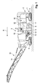
- Fig. 1 shows a side view of a road milling machine as an example of a milling machine in a simplified schematic representation.
- the milling machine can also be a recycler, stabilizer or surface miner.
- the milling machine has a machine frame 2 carried by a chassis 1 with an operator's platform 3.
- the chassis 1 of the milling machine can comprise four drives 4, 5, which are arranged on the rear and front on both sides of the machine frame 2.
- the steerable drives 4, 5, in particular chain drives, which allow translational and / or rotary movements of the milling machine, are attached to lifting cylinders 6, 7 which are attached to the machine frame 1 so that the machine frame is adjustable in height.
- the drives 4, 5 can be chain drives. Instead of chain drives, wheels can also be provided.
- the milling machine has a drive machine 16, in particular an internal combustion engine, arranged on the machine frame.
- the drive power of the internal combustion engine is transmitted to hydraulic pumps via a pump transfer gear in order to supply hydraulic motors provided in the drives 4, 5 of the milling machine with hydraulic fluid.
- the milling machine has a milling / cutting drum 8 which is arranged in a milling drum housing 9.
- the milling drum 8 is driven by the single drive machine, the drive power of the drive machine 16 being transmitted to the milling / cutting drum 8 via a mechanical gear 32.
- a device, not shown, for supplying water into the milling drum housing is provided, which has a pump device, not shown.
- the individual assemblies can in turn comprise several different components, for example actuators, sensors, etc., which, however, are also not shown since they are generally known to the person skilled in the art.
- a conveyor device 13 with a conveyor belt 14 is provided for transporting away the material removed by the milling / cutting drum.
- the machine operator can enter various operating parameters with an operating unit 15, which can be provided on the operator's platform 3.
- an operating unit 15 can be provided on the operator's platform 3.
- the relevant components of the individual assemblies are controlled with a central control and computing unit. However, several individual control and computing units can also be provided.
- the control and computing unit can, for example, be a general processor, a digital signal processor (DSP) for continuous processing of digital signals, a microprocessor, an application-specific integrated circuit (ASIC), an integrated circuit (FPGA) consisting of logic elements or other integrated circuits (IC) or have hardware components in order to carry out the individual method steps.
- DSP digital signal processor
- ASIC application-specific integrated circuit
- FPGA integrated circuit
- a data processing program software can run on the hardware components to carry out the method steps.
- a plurality or combination of the various components is also possible.
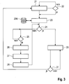
- Fig. 2 shows a simplified block diagram with the essential components of the milling machine.
- the drive device comprises the drive machine 16 and the drives, not shown, each having a hydraulic motor.
- the working device comprises, as a common component with the drive device, the milling / cutting roller 8, the hold-down device 10 arranged in front of the milling / cutting roller in the working direction, the scraper 11 behind the milling / cutting roller and the edge protection 12 on both sides of the Milling / cutting drum.
- Another assembly of the working device is the device 18 for adjusting the height of the machine frame 1, which has the four lifting columns 6, 7 so that the milling depth can be adjusted.
- the working device has the device 19 for supplying water with the pumping device and the conveying device 13 with the conveyor belt 14. The individual assemblies are connected to the central control and computing unit 20 via control lines 33.
- the speed of the drive machine 16 determines the speed n of the milling / cutting roller 8, which is driven by the drive machine via the mechanical transmission 32, while the feed speed v is set by setting the hydraulic pumps for the hydraulic motors accordingly.
- the operating unit 15 has an input unit 15A which, for example, can have buttons, switches, sliders, a keyboard or a touch screen in order to be able to enter certain parameters manually.
- the input unit 15A can also have a joystick for controlling the machine, in particular the steerable drives.
- the operating unit has a display unit 15B, for example a screen.
- micro-milling I micro-milling II, fine milling I, fine milling II, standard milling I, standard milling II, standard milling III, rough milling (rough milling), whereby different milling tasks can be selected for the individual milling types.
- the individual milling tasks are identified with the index "I", "II” or "III”.
- the milling tasks can be different milling patterns, which can differ in the roughness of the surface.
- Different framework conditions can also be taken into account, for example the type of subsoil (concrete or asphalt), or whether the soil should be processed as quickly as possible or with little wear.
- a data record is assigned to each operating mode and is stored in a memory 20A of the control and computing unit 20.
- Each data record contains the drive and work parameters that are considered optimal for the respective task.
- the data record does not have to contain all of the parameters that need to be set in order to complete the task.
- the data record also cannot contain individual operating parameters, in particular those parameters that should be able to be changed by the machine operator during operation of the milling machine. These parameters can be entered manually by the machine operator using the control unit.
- the machine operator selects an operating mode M 1 to M n with the selection unit 15C, for example by turning a rotary switch on the operating unit 15, for example the operating mode "Fine milling I" (block 21: "Selection of an operating mode”).
- the present exemplary embodiment provides an additional test routine.
- the milling / cutting roller used is identified by an identifier, for example a barcode, which is read out by a reader (not shown).
- the data set that corresponds to the operating mode "Fine milling I" is assigned, contains a list of identifications of different milling / cutting drums with which the milling task can be carried out, for example milling drum types for fine milling.
- the control and computing unit 20 checks whether the identification of the milling / cutting roller used is entered in the list (block 22: “Compatibility with roller?”). If this is the case, it is concluded that the milling machine is equipped with the correct milling drum type for "fine milling I". Thereupon the drive and working parameters are read out of the memory 20A, which are assigned to the operating mode “fine milling I” (block 23: “reading out operating parameters”). At this point in time, the machine is not yet in operation, ie the machine is at a standstill and the milling / cutting roller is not lowered (block 24: “Machine in operation?).
- the next step is to ask whether the milling operation should be started (block 25: "Start milling operation?). If this is the case, the The drive and work parameters required for starting the milling operation are based on the further control (block 26: “Setting the operating parameters for starting the machine”).
- one of the operating parameters for setting the milling machine is a speed n A for the drive machine is specified, which is, for example, 1600 1 / min, so that sufficient power is available for the attachment.
- the milling depth is not specified as a working parameter for the attachment, since the milling / cutting roller 8 is actuated by the machine operator by actuating the lifting columns 5, 6 is lowered manually to the desired depth (block 27: “Lowering to milling depth") lowering the milling / cutting roller 8, ie setting the milling depth, the machine operator sets the drives 4, 5 in motion (block 28: “Start up”). The milling machine is thus put into operation (block 24: “Milling machine in operation?”).
- the individual subassemblies of the milling machine are controlled by the control and computing unit 20 in such a way that the subassemblies carry out the respective machine functions on the basis of the drive and work parameters of the "Fine milling I" operating mode (block 29: “Setting the operating parameters for Milling mode ").
- the method steps carried out taking into account the selected operating mode are described in detail with reference to block 29.
- the control and computing unit 20 sets, for example, the motor speed n as an operating parameter, which can be a different speed than when the milling / cutting drum is applied.
- This motor speed n can also be contained in the data record "Precision Milling I" as a fixed, predetermined variable.
- the data record "Fine milling II” can differ from the data record "Fine milling I” in that the working parameter of the engine speed n for "Fine milling II" is greater or smaller than the working parameter of the engine speed n for "Fine milling I".
- the engine speed as an example of a working parameter, u. a. influences the milling drum speed, which determines the quality of the milling pattern.
- fine milling II is an operating mode with a finer milling pattern, i. H. a surface with a lower roughness should be, the required milling drum speed and thus the required motor speed n for "fine milling II” is greater than for "fine milling I".
- the milling pattern is also determined by the feed speed v of the milling machine, which the machine operator can change while the machine is in operation.
- a higher feed speed v requires a higher milling drum speed and thus a higher motor speed n.
- the feed speed v and the motor speed n are therefore related.
- a fixed value is therefore not specified for the motor speed n, but a value that is dependent on the feed rate v.
- different functions are stored in the memory 20A of the control and computing unit 20, which functions can differ from one another, for example in the constant k.
- the relationship between the feed rate v and the engine speed n can also be a non-linear relationship.
- the engine speed is particularly preferably regulated in discrete steps. For example, engine speeds of 1200 min -1 , 1600 min -1 , 1800 min -1 and 2100 min -1 can be provided for the milling operation. In this case, it is particularly preferable to keep the ratio v / n between feed and motor speed in a certain range.
- the motor speed can be adjusted when the limit values for the feed rate are exceeded or not reached.
- different functions can therefore be stored in the memory 20A of the control and arithmetic unit 20, which differ, for example, in the predefined areas in which the ratio between the feed rate and the motor speed should vary.
- the computing and evaluation unit uses the function stored for "Fine milling I" to calculate the required motor speed n, which can be a different speed for "Fine milling I” than, for example, for the "Fine milling" operating mode II “or” rough milling ".
- the control and computing unit 20 continuously monitors which feed rate the machine operator has specified. If the machine operator has changed the feed rate, the control and arithmetic unit 20 calculates the new motor speed with the function stored for the selected operating mode and then sets the new motor speed (block 29: "Setting the operating parameters for milling operation").
- the function can also be used to calculate and set the feed speed v after specifying a motor speed n.
- a drive parameter can determine a working parameter when controlling the individual assemblies, or vice versa.
- the working parameters for controlling the other assemblies of the working device are read out for the milling operation in order to control actuators or other drive devices of these assemblies.
- These parameters include in particular the height h of the hold-down device 10, scraper 11 and edge protection 12 or their bearing force on the floor.
- the height of the hold-down 10, stripper 11 and edge protection 12 is particularly dependent on the height of the machine frame 1 in relation to the surface of the floor, which in turn determines the milling depth.
- the control and arithmetic unit 20 sets the hold-down device 10, the stripper 11 and the edge protection 12 to the height or the bearing force predetermined by the parameters.
- the control and computing unit 20 also controls the pumping device of the device 19 for supplying water into the milling drum housing 9 in such a way that the amount of water is supplied that is specified by the corresponding working parameter for the "Fine milling 1" operating mode.
- This amount of water can be smaller than the amount of water that is specified by the corresponding working parameter for standard milling machines I, II, III, which in turn can be smaller than the amount of water for rough milling.
- control and computing unit 20 can also control the conveying device 13 present in milling machines, since, for example, the "fine milling" operating mode requires the setting of a smaller conveying quantity than "coarse milling".
- the above-mentioned operating parameters can not only be fixedly predefined sizes, but also sizes that are dependent on other operating parameters, as is the case, for example, for the speed of the milling / cutting roller.
- the modules described above can therefore also be controlled on the basis of the function describing the dependency of an operating parameter of a module on at least one operating parameter of at least one other module, which function is stored in the memory for the operating mode selected with the selection unit. For the start of the milling operation, depending on the operating mode, a predetermined value can first be set and then changed during the milling operation depending on at least one operating parameter.
- the operating parameters mentioned above can also depend on several other operating parameters.
- the engine speed n can be regulated not only as a function of the feed rate v, but also as a function of the power requirement of the consumers driven by the drive unit. Consequently, different specifications can be made for the various operating modes.
- the motor speed can be a function dependent on the feed, in which a specific minimum motor speed is functionally assigned to a specific feed speed, for example 1600 min -1 at a feed of 15 m / min.
- a specific minimum motor speed is functionally assigned to a specific feed speed, for example 1600 min -1 at a feed of 15 m / min.
- the motor speed is increased independently of the feed rate. If the feed rate is then increased, this can lead to a further increase in the motor speed depending on the functional relationship mentioned above, if the minimum motor speed determined as a function of the feed rate is above the currently set motor speed.
- the setting of the delivery rate of the pumping device of the device 19 for supplying water into the milling drum housing 9 can, for example, be based on a predetermined function that is stored in the memory 20C and is read out of the memory for the selected operating mode, depending on at least one Operating parameters of an assembly or several assemblies can be set.
- the function can describe the dependency of the delivery rate on the feed rate (drive parameters) and the milling depth (working parameters), whereby the delivery rate should increase with increasing feed rate and should also increase with increasing milling depth.
- the previously specified and set operating parameters are continuously monitored, with the control and computing unit 20 continuously checking whether the operating parameters previously read out from the memory 20A, on the basis of which the control is currently taking place, have been changed (block 31: "Modification Operating parameters? "). If the parameters have been changed, the new parameter sets are queried. If this is not the case, control of the machine continues on the basis of the previous parameters.
Landscapes
- Engineering & Computer Science (AREA)
- Mining & Mineral Resources (AREA)
- Mechanical Engineering (AREA)
- Architecture (AREA)
- Civil Engineering (AREA)
- Structural Engineering (AREA)
- Life Sciences & Earth Sciences (AREA)
- General Life Sciences & Earth Sciences (AREA)
- Geochemistry & Mineralogy (AREA)
- Geology (AREA)
- Road Repair (AREA)
- Numerical Control (AREA)
Description
Die Erfindung betrifft eine Fräsmaschine, insbesondere Straßenfräsmaschine, Stabilisierer, Recycler oder Surface-Miner, mit einer Antriebseinrichtung, die derart ausgebildet ist, dass die Fräsmaschine auf dem Boden translatorische und/oder rotarische Bewegungen ausführt, und einer Arbeitseinrichtung, die derart ausgebildet ist, dass der Boden bearbeitet wird. Darüber hinaus betrifft die Erfindung ein Verfahren zum Betrieb einer derartigen Fräsmaschine.The invention relates to a milling machine, in particular a road milling machine, stabilizer, recycler or surface miner, with a drive device which is designed such that the milling machine executes translational and / or rotary movements on the ground, and a working device which is designed such that the soil is worked. The invention also relates to a method for operating such a milling machine.
Es sind unterschiedliche Ausführungsformen von Bodenfräsmaschinen bekannt, zu denen insbesondere die Straßenfräsmaschinen, Stabilisierer, Recycler oder Surface-Miner zählen. Die bekannten Fräsmaschinen zeichnen sich durch eine Antriebseinrichtung zum Ausführen von translatorischen und/oder rotarischen Bewegungen der Maschine auf dem Boden und eine Arbeitseinrichtung zum Bearbeiten des Bodens aus. Die Antriebseinrichtung verfügt über mindestens eine Baugruppe, die in Abhängigkeit von Antriebsparametern eine bestimmte Maschinenfunktion ausführt, und die Arbeitseinrichtung verfügt über mindestens eine Baugruppe, die in Abhängigkeit von Arbeitsparametern eine bestimmte Maschinenfunktion ausführt. Die einzelnen Baugruppen der Antriebseinrichtung und Arbeitseinrichtung können wiederum mehrere Bauteile umfassen.Different embodiments of ground milling machines are known, which include road milling machines, stabilizers, recyclers or surface miners in particular. The known milling machines are characterized by a drive device for performing translational and / or rotary movements of the machine on the floor and a working device for working the floor. The drive device has at least one assembly that performs a specific machine function as a function of drive parameters, and the work device has at least one assembly that performs a specific machine function as a function of work parameters. The individual assemblies of the drive device and working device can in turn comprise several components.
Nachfolgend werden unter einer Antriebseinrichtung sämtliche Bauteile der Straßenfräsmaschine verstanden, die dazu bestimmt oder geeignet sind, die Maschine zu verfahren, und unter einer Arbeitseinrichtung werden sämtliche Bauteile der Straßenfräsmaschine verstanden, die dazu bestimmt oder geeignet sind, bei der Bearbeitung des Bodens zum Einsatz zu kommen. Die Antriebseinrichtung und Arbeitseinrichtung können auch gemeinsame Bauteile haben. Ein gemeinsames Bauteil der Antriebs- und Arbeitseinrichtung kann eine Antriebsmaschine, insbesondere ein Verbrennungsmotor, sein.In the following, a drive device is understood to mean all components of the road milling machine that are intended or suitable for moving the machine, and a work device is understood to mean all components of the road milling machine that are intended or suitable to be used in the processing of the ground . The drive device and working device can also have common components. A common component of the drive and work device can be a drive machine, in particular an internal combustion engine.
Die Antriebsleistung des Verbrennungsmotors kann über ein Pumpenverteilergetriebe auf Hydraulikpumpen übertragen werden, um in den Laufwerken der Fräsmaschine vorgesehene Hydraulikmotoren mit Hydraulikflüssigkeit zu versorgen. Die Antriebeinrichtung umfasst dann den Verbrennungsmotor, das Pumpenverteilergetriebe, die Hydraulikpumpen und die Laufwerke mit den Hydraulikmotoren. Die Vorschubgeschwindigkeit der Fräsmaschine kann bei unterschiedlichen Drehzahlen des Verbrennungsmotors durch eine entsprechende Einstellung der Hydraulikpumpen stufenlos geregelt werden.The drive power of the internal combustion engine can be transmitted to hydraulic pumps via a pump transfer gear in order to supply hydraulic motors provided in the drives of the milling machine with hydraulic fluid. The drive device then comprises the internal combustion engine, the pump transfer gear, the hydraulic pumps and the drives with the hydraulic motors. The feed speed of the milling machine can be continuously regulated at different speeds of the internal combustion engine by setting the hydraulic pumps accordingly.
Eine wesentliche Baugruppe der Arbeitseinrichtung ist die Fräs/-Schneidwalze, die bei den bekannten Fräsmaschinen in einem Fräswalzengehäuse angeordnet ist. Die Fräs/- Schneidwalze wird im Allgemeinen von der einzigen Antriebsmaschine der Fräsmaschine angetrieben, wobei die Antriebsleistung der Antriebsmaschine über ein mechanisches Getriebe auf die Fräs/-Schneidwalze übertragen wird. Die Drehzahl der Fräs/- Schneidwalze wird somit von der Drehzahl des Verbrennungsmotors und dem Übersetzungsverhältnis des Getriebes bestimmt. Die Fräs-/Schneidwalze kann beispielsweise auch hydraulisch angetrieben werden, wobei die Drehzahl über eine entsprechende Verstellung der Hydraulikpumpen geregelt wird.An essential assembly of the working device is the milling / cutting roller, which is arranged in a milling drum housing in the known milling machines. The milling / cutting drum is generally driven by the single drive machine of the milling machine, the drive power of the drive machine being transmitted to the milling / cutting drum via a mechanical gear. The speed of the milling / cutting drum is thus determined by the speed of the internal combustion engine and the transmission ratio of the gearbox. The milling / cutting drum can, for example, also be driven hydraulically, with the speed being controlled by adjusting the hydraulic pumps accordingly.
Die Arbeitseinrichtung kann aber noch weitere Baugruppen umfassen, die für die Bearbeitung des Bodens mit der Fräs/-Schneidwalze zusammenwirken. Hierzu zählen beispielsweise ein in der Höhe gegenüber dem Boden verstellbarer Niederhalter, der in Arbeitsrichtung der Fräsmaschine vor der Fräs-/Schneidwalze angeordnet ist, oder ein in der Höhe gegenüber dem Boden verstellbarer und mit einer vorgegebenen Auflagekraft auf dem Boden aufliegender Abstreifer, der in Arbeitsrichtung der Fräsmaschine hinter der Schneid-/Fräswalze angeordnet ist, oder ein in der Höhe gegenüber dem Boden verstellbarer und mit einer vorgegebenen Auflagekraft auf dem Boden aufliegender Kantenschutz, der in Längsrichtung der Fräsmaschine angeordnet ist.The working device can, however, also comprise further assemblies which cooperate with the milling / cutting roller for processing the soil. These include, for example, a hold-down device which is adjustable in height relative to the floor and which is arranged in front of the milling / cutting roller in the working direction of the milling machine, or a scraper which is adjustable in height relative to the floor and rests on the floor with a predetermined contact force, which in the working direction of the milling machine is arranged behind the cutting / milling drum, or an edge protection which is adjustable in height relative to the floor and rests on the floor with a predetermined contact force and is arranged in the longitudinal direction of the milling machine.
Fräsmaschinen verfügen einer zentrale Steuer- und Recheneinheit, die derart konfiguriert ist, dass die Baugruppen der Antriebseinrichtung derart angesteuert werden, dass eine bestimmte Maschinenfunktion ausgeführt wird, und die Baugruppen der Arbeitseinrichtung derart angesteuert werden, dass eine bestimmte Maschinenfunktion ausgeführt wird. Die Ausführung einer bestimmten Maschinenfunktion erfolgt in Abhängigkeit von bestimmten Betriebsparametern, die vom Maschinenführer vorgegeben werden. Nachfolgend werden die Betriebsparameter, die bei der Ansteuerung der Baugruppen der Antriebeinrichtung Berücksichtigung finden, als Antriebparameter und unter den Parametern, die bei der Ansteuerung der Baugruppen der Arbeitseinrichtung Berücksichtigung finden, als Arbeitsparameter bezeichnet.Milling machines have a central control and computing unit which is configured in such a way that the assemblies of the drive device are controlled in such a way that a specific machine function is performed, and the assemblies of the Work equipment can be controlled in such a way that a certain machine function is performed. The execution of a certain machine function takes place as a function of certain operating parameters that are specified by the machine operator. In the following, the operating parameters that are taken into account when controlling the assemblies of the drive device are referred to as drive parameters and, among the parameters that are considered when controlling the assemblies of the working device, are referred to as working parameters.
Zur Eingabe der Antrieb- und Arbeitsparameter weisen Fräsmaschinen eine Bedieneinheit auf, die unterschiedlich ausgebildet sein kann. Die Bedieneinheit kann beispielsweise Taster oder Schalter, Schieber, Steuerknüppel aufweisen oder als Touch-Screen ausgebildet sein.For inputting the drive and work parameters, milling machines have an operating unit that can be designed in different ways. The operating unit can, for example, have buttons or switches, sliders, control sticks or be designed as a touch screen.
Die Bedienung einer Fräsmaschine ist für den Maschinenführer eine komplexe Aufgabe. Der Maschinenführer muss sämtliche Antriebs- und Arbeitsparameter so vorgeben, dass das gewünschte Fräsergebnis erreicht wird. Dabei muss der Maschinenführer berücksichtigen, dass die Vorgabe eines Betriebsparameters unmittelbar einen Einfluss auf einen anderen Parameter ausüben kann. Denn beim Betrieb der Fräsmaschine ist für die Qualität des Fräsbildes das Zusammenspiel sämtlicher Parameter entscheidend. Daher setzt die Bedienung einer Fräsmaschine eine große Erfahrung des Maschinenführers voraus.Operating a milling machine is a complex task for the machine operator. The machine operator must specify all drive and work parameters so that the desired milling result is achieved. The machine operator must take into account that the specification of one operating parameter can directly influence another parameter. Because when operating the milling machine, the interaction of all parameters is decisive for the quality of the milling pattern. Therefore, the operation of a milling machine requires a great deal of experience on the part of the machine operator.
Die
Die
Die
Die
Der Erfindung liegt die Aufgabe zugrunde, eine Fräsmaschine mit einer vereinfachten Bedienung für den Maschinenführer zu schaffen. Darüber hinaus ist eine Aufgabe der Erfindung, ein Verfahren zum Betrieb einer Fräsmaschine anzugeben, das die Bedienung der Maschine vereinfacht.The invention is based on the object of creating a milling machine with simplified operation for the machine operator. In addition, an object of the invention is to provide a method for operating a milling machine that simplifies the operation of the machine.
Die Lösung dieser Aufgaben erfolgt mit den Merkmalen der unabhängigen Ansprüche. Die abhängigen Ansprüche betreffen vorteilhafte Ausführungsformen der Erfindung.These tasks are achieved with the features of the independent claims. The dependent claims relate to advantageous embodiments of the invention.
Die erfindungsgemäße Fräsmaschine verfügt über eine Bedieneinheit zur Eingabe von Betriebsparametern zur Steuerung der Antriebseinrichtung und der Arbeitseinrichtung. Mit der Bedieneinheit kann der Maschinenführer sämtliche für das Projekt wesentliche Parameter eingeben. Der Maschinenführer kann beispielsweise die Motorleistung der Antriebsmaschine, die Vorschubgeschwindigkeit der Fräsmaschine, die Frästiefe oder die Drehzahl der Fräswalze einstellen. Bei der erfindungsgemäßen Fräsmaschine ist aber für die jeweilige Fräsaufgabe die Einstellung sämtlicher Antriebs- und Arbeitsparameter nicht erforderlich.The milling machine according to the invention has an operating unit for entering operating parameters for controlling the drive device and the working device. With the operator can enter all the parameters essential for the project into the control unit. The machine operator can, for example, set the motor power of the drive machine, the feed speed of the milling machine, the milling depth or the speed of the milling drum. In the case of the milling machine according to the invention, however, it is not necessary to set all of the drive and working parameters for the respective milling task.
Die Bedieneinheit zeichnet sich durch eine Auswahleinheit zur Auswahl eines Betriebsmodus aus einer Mehrzahl von Betriebsmodi aus. Folglich braucht der Maschinenführer für das Projekt nur einen Betriebsmodus auszuwählen. Wenn die Aufgabe beispielsweise Feinfräsen ist, um ein feines Fräsbild zu erzielen, braucht der Maschinenführer nur den Betriebsmodus Feinfräsen auszuwählen. Für das Feinfräsen können in Abhängigkeit von der jeweiligen Fräsaufgabe auch mehrere Betriebsmodi vorgesehen sein, bei der die erforderliche Arbeitszeit oder der Verschleiß der Fräswerkzeuge Berücksichtigung finden kannThe operating unit is distinguished by a selection unit for selecting an operating mode from a plurality of operating modes. As a result, the machine operator only needs to select one operating mode for the project. If the task is fine milling, for example, in order to achieve a fine milling pattern, the machine operator only needs to select the fine milling operating mode. For fine milling, depending on the respective milling task, several operating modes can be provided, in which the required working time or the wear of the milling tools can be taken into account
Die Steuer- und Recheneinheit weist einen Speicher auf, in dem für jeden Betriebsmodus der Mehrzahl von Betriebsmodi mindestens zwei vorgegebene Betriebsparameter, die dem Betriebsmodus zugewiesen werden, gespeichert sind. Die betreffenden Betriebsparameter brauchen daher vom Maschinenführer nicht eingestellt zu werden, sondern können aus dem Speicher ausgelesen werden.The control and computing unit has a memory in which at least two predetermined operating parameters, which are assigned to the operating mode, are stored for each operating mode of the plurality of operating modes. The relevant operating parameters therefore do not need to be set by the machine operator, but can be read from the memory.
Die Steuer- und Recheneinheit ist derart konfiguriert, dass mindestens eine Baugruppe in Abhängigkeit von den mindestens zwei Betriebsparametern, welche für den mit der Auswahleinheit ausgewählten Betriebsmodus in dem Speicher gespeichert sind, derart angesteuert wird, dass die jeweilige Maschinenfunktion ausgeführt wird. Wenn zwei Baugruppen angesteuert werden, kann jede Baugruppe auf der Grundlage eines Betriebsparameters der mindestens zwei Betriebsparameter angesteuert werden. Folglich wird die Fräsmaschine mit den Betriebsparametern gesteuert, die dem vom Maschinenführer ausgewählten Betriebsmodus zugewiesen sind. Die Zuweisung der Parameter braucht daher nicht von dem Maschinenführer vorgenommen zu werden, so dass der Maschinenführer entlastet wird. Allein mit der Auswahl des Betriebsmodus wird somit ein optimales Fräsergebnis erzielt.The control and computing unit is configured in such a way that at least one assembly is controlled as a function of the at least two operating parameters which are stored in the memory for the operating mode selected with the selection unit in such a way that the respective machine function is executed. If two modules are controlled, each module can be controlled on the basis of an operating parameter of the at least two operating parameters. As a result, the milling machine is controlled with the operating parameters assigned to the operating mode selected by the machine operator. The machine operator therefore does not need to assign the parameters, see above that the machine operator is relieved. An optimal milling result is achieved simply by selecting the operating mode.
Die Betriebsparameter umfassen Antriebsparameter und Arbeitsparameter, wobei die Antriebseinrichtung mindestens eine Baugruppe aufweist, die in Abhängigkeit von Antriebsparametern eine bestimmte Maschinenfunktion ausführt, und die Arbeitseinrichtung mindestens eine Baugruppe aufweist, die in Abhängigkeit von Arbeitsparametern eine bestimmte Maschinenfunktion ausführt. In dem Speicher für jeden Betriebsmodus der Mehrzahl von Betriebsmodi können mindestens zwei vorgegebene Arbeitsparameter, die dem Betriebsmodus zugewiesen sind, gespeichert sein. Bei dieser Ausführungsform ist die Steuer- und Recheneinheit derart konfiguriert, dass mindestens eine Baugruppe der Arbeitseinrichtung in Abhängigkeit von den mindestens zwei Arbeitsparametern, welche für den mit der Auswahleinheit ausgewählten Betriebsmodus in dem Speicher gespeichert sind, derart angesteuert wird, dass die jeweilige Maschinenfunktion ausgeführt wird.The operating parameters include drive parameters and work parameters, the drive device having at least one assembly that performs a specific machine function as a function of drive parameters, and the work device having at least one assembly that performs a specific machine function as a function of work parameters. In the memory for each operating mode of the plurality of operating modes, at least two predefined working parameters that are assigned to the operating mode can be stored. In this embodiment, the control and computing unit is configured in such a way that at least one assembly of the working device is controlled depending on the at least two working parameters stored in the memory for the operating mode selected with the selection unit in such a way that the respective machine function is executed .
Die Vorschubgeschwindigkeit ist ein Antriebsparameter, der vorzugsweise vom Maschinenführer selbst vorgegeben werden kann und auch vom Maschinenführer während des Betriebs der Baumaschine verändert werden kann. Daher ist bei einer bevorzugten Ausführungsform die Vorschubgeschwindigkeit ein mit der Bedieneinheit zur Steuerung der Antriebseinrichtung eingebbarer Antriebsparameter. Es kann aber auch vorgesehen sein, dass der Maschinenführer Arbeitsparameter, beispielsweise die Frästiefe, vorgibt.The feed rate is a drive parameter that can preferably be specified by the machine operator himself and can also be changed by the machine operator while the construction machine is in operation. Therefore, in a preferred embodiment, the feed rate is a drive parameter that can be entered with the operating unit for controlling the drive device. However, it can also be provided that the machine operator specifies working parameters, for example the milling depth.
Die erfindungsgemäße Fräsmaschine kann weiterhin vorsehen, dass für jeden Betriebsmodus der Mehrzahl von Betriebsmodi mindestens eine die Abhängigkeit eines Betriebsparameters einer Baugruppe von mindestens einem Betriebsparameter mindestens einer anderen Baugruppe beschreibende Funktion gespeichert ist. Unter einer derartigen Funktion werden sämtliche Angaben verstanden, die einen Zusammenhang zwischen dem einen und dem anderen Parameter beschreiben. Diese Funktion kann beispielsweise auch ein Kennlinienfeld sein. Bei dieser bevorzugten Ausführungsform ist die Steuer- und Recheneinheit weiterhin derart konfiguriert, dass auf der Grundlage der die Abhängigkeit eines Betriebsparameters einer Baugruppe von mindestens einem Betriebsparameter mindestens einer anderen Baugruppe beschreibenden Funktion, welche für den mit der Auswahleinheit ausgewählten Betriebsmodus in dem Speicher gespeichert ist, mindestens eine Baugruppe der Arbeitseinrichtung oder Antriebseinrichtung derart angesteuert, dass die jeweilige Maschinenfunktion ausgeführt wird. Folglich kann bei der Steuerung der Fräsmaschine nicht nur ein vorgegebener Betriebsparameter einer Baugruppe, sondern auch ein Zusammenhang zwischen vorgegebenen Parametern unterschiedlicher Baugruppen Berücksichtigung finden.The milling machine according to the invention can furthermore provide that for each operating mode of the plurality of operating modes at least one function describing the dependence of an operating parameter of an assembly on at least one operating parameter of at least one other assembly is stored. Such a function is understood to mean all information that has a connection between the describe one and the other parameter. This function can also be a family of characteristics, for example. In this preferred embodiment, the control and computing unit is further configured in such a way that on the basis of the function describing the dependency of an operating parameter of an assembly on at least one operating parameter of at least one other assembly, which is stored in the memory for the operating mode selected with the selection unit, at least one assembly of the working device or drive device is controlled in such a way that the respective machine function is carried out. Consequently, when controlling the milling machine, not only a predefined operating parameter of an assembly, but also a relationship between predefined parameters of different assemblies can be taken into account.
Die Steuer-und Recheneinheit ist derart konfiguriert, dass auf der Grundlage der die Abhängigkeit eines Arbeitsparameters einer Baugruppe von mindestens einem Antriebsparameter mindestens einer anderen Baugruppe beschreibenden Funktion oder auf der Grundlage der die Abhängigkeit eines Antriebsparameters einer Baugruppe von mindestens einem Arbeitsparameters mindestens einer anderen Baugruppe beschreibenden Funktion, welche für den mit der Auswahleinheit ausgewählten Betriebsmodus in dem Speicher gespeichert ist, mindestens eine Baugruppe der Arbeitseinrichtung bzw. Antriebseinrichtung derart angesteuert wird, dass die jeweilige Maschinenfunktion ausgeführt wird.The control and computing unit is configured such that, on the basis of the function describing the dependency of a working parameter of an assembly on at least one drive parameter of at least one other assembly, or on the basis of the function describing the dependence of a drive parameter of an assembly on at least one working parameter of at least one other assembly Function which is stored in the memory for the operating mode selected with the selection unit, at least one assembly of the working device or drive device is controlled in such a way that the respective machine function is carried out.
Für die Erfindung ist grundsätzlich unerheblich, welche Maschinenfunktionen die einzelnen Baugruppen ausführen. Bei bestimmten Maschinenfunktionen kommen aber die Vorteile der Erfindung besonders zum Tragen.For the invention it is fundamentally irrelevant which machine functions the individual assemblies perform. However, the advantages of the invention are particularly evident in certain machine functions.
Bei einer Ausführungsform umfasst eine Baugruppe der Antriebseinrichtung motorisch angetriebene Laufwerke, auf denen die Baumaschine aufsteht, wobei ein Antriebsparameter die Vorschubgeschwindigkeit der Fräsmaschine ist, und eine Baugruppe der Arbeitseinrichtung umfasst eine motorisch angetriebene Fräs-/Schneidwalze, wobei ein Arbeitsparameter die Drehzahl der Fräs-/Schneidwalze ist. Bei dieser Ausführugsform ist eine die Abhängigkeit eines Arbeitsparameters einer Baugruppe von einem Antriebsparameter einer anderen Baugruppe beschreibende Funktion eine die Abhängigkeit der Drehzahl der Fräs-/Schneidwalze von der Vorschubgeschwindigkeit der Fräsmaschine beschreibende Funktion. Die Steuer- und Recheneinheit ist bei dieser Ausführungsform derart konfiguriert ist, dass auf der Grundlage der die Abhängigkeit der Drehzahl der Fräs-/Schneidwalze von der Vorschubgeschwindigkeit der Fräsmaschine beschreibenden Funktion, welche für den mit der Auswahleinheit ausgewählten Betriebsmodus in dem Speicher gespeichert ist, für eine vorgegebene Vorschubgeschwindigkeit die Drehzahl der Fräs-/Schneidwalze eingestellt wird. Alternativ kann bei manueller Änderung der Drehzahl der Fräs-/Schneidwalze die Vorschubgeschwindigkeit der Maschine angepasst werden.In one embodiment, an assembly of the drive device comprises motor-driven drives on which the construction machine stands, one drive parameter being the feed rate of the milling machine, and an assembly of the working device comprises a motor-driven milling / cutting roller, one working parameter being the speed of the milling / cutting drum. Cutting roller is. At In this embodiment, a function describing the dependency of a working parameter of an assembly on a drive parameter of another assembly is a function describing the dependence of the speed of the milling / cutting drum on the feed speed of the milling machine. The control and processing unit is configured in this embodiment in such a way that on the Based on the function describing the dependence of the speed of the milling / cutting roller on the feed speed of the milling machine, which is stored in the memory for the operating mode selected with the selection unit, the speed of the milling / cutting roller is set for a predetermined feed speed. Alternatively, if the speed of the milling / cutting drum is changed manually, the feed speed of the machine can be adjusted.
Beispielsweise kann für den Betriebsmodus des Feinfräsens eine bestimmte Vorschubgeschwindigkeit der Baumaschine, die einen Antriebsparameter darstellt, vor Beginn der Fräsarbeiten von dem Maschinenführer vorgegeben oder auch während der Fräsarbeiten verändert werden, wobei die Einstellung der zugehörigen Drehzahl der Fräs-/Schneidwalze, die einen Arbeitsparameter darstellt, dann in Abhängigkeit von der Vorschubgeschwindigkeit automatisch erfolgt. Für unterschiedliche Fräsaufgaben können dabei unterschiedliche Abhängigkeiten vorgegeben werden, so dass für die ausgewählte Fräsaufgabe eine optimale Einstellung erfolgt. Eine Ausführungsform kann vorsehen, dass die Mehrzahl der mit der Auswahleinheit auswählbaren Betriebsmodi zumindest einen Feinfräs-Betriebsmodus für ein feineres Fräsbild bei einer kleineren Frästiefe der Fräs-/Schneidwalze und einen Grobfräs-Betriebsmodus für ein gröberes Fräsbild bei einer größeren Frästiefe der Fräs-/Schneidwalze umfasst, wobei für den Feinfräs-Betriebsmodus in dem Speicher eine Funktion gespeichert ist, die bei einer vorgegebenen Vorschubgeschwindigkeit für den Feinfräs-Betriebsmodus eine höhere Drehzahl der Fräs-/Schneidwalze vorgibt als für den Grobfräs-Betriebsmodus. Dem Maschinenführer können aber auch mehrere Fräs-Betriebsmodi, die sich in der Qualität des Fräsbildes unterscheiden, zur Auswahl angeboten werden.For example, for the fine milling operating mode, a certain feed rate of the construction machine, which represents a drive parameter, can be specified by the machine operator before the start of the milling work or changed during the milling work, with the setting of the associated speed of the milling / cutting roller, which represents a work parameter , then takes place automatically depending on the feed rate. Different dependencies can be specified for different milling tasks, so that an optimal setting is made for the selected milling task. One embodiment can provide that the majority of the operating modes that can be selected with the selection unit have at least one fine milling operating mode for a finer milling image with a smaller milling depth of the milling / cutting drum and one coarse milling operating mode for a coarser milling image with a greater milling depth of the milling / cutting drum comprises, wherein a function is stored for the fine milling operating mode in the memory, which specifies a higher speed of the milling / cutting roller than for the rough milling operating mode at a predetermined feed rate for the fine milling operating mode. The machine operator can, however, also be offered a choice of several milling operating modes that differ in the quality of the milling pattern.
Bei einer anderen Ausführungsform ist eine Baugruppe der Arbeitseinrichtung ein Einrichtung zum Zuführen von Wasser in einen die Fräs-/Schneidwalze aufnehmendes Fräs/-Schneidwalzengehäuse mit einer motorisch angetriebenen Pumpeinrichtung, wobei ein Arbeitsparameter die Fördermenge der Pumpeinrichtung ist. Bei dieser Ausführungsform kann beispielsweise für den Feinfräs-Betriebsmodus in dem Speicher ein Arbeitsparameter gespeichert, der bei einer vorgegebenen Vorschubgeschwindigkeit für den Feinfräs-Betriebsmodus eine geringere Fördermenge der Pumpeinrichtung vorgibt als für den Grobfräs-Betriebsmodus.In another embodiment, an assembly of the working device is a device for supplying water into a milling / cutting drum housing accommodating the milling / cutting drum with a motor-driven pump device, one working parameter being the delivery rate of the pump device. In this embodiment, for example, for the fine milling operating mode, a working parameter can be stored in the memory, which at a predetermined feed rate for the fine milling operating mode specifies a lower delivery rate of the pumping device than for the coarse milling operating mode.
Bei einer weiteren Ausführungsform ist eine Baugruppe der Arbeitseinrichtung eine motorisch angetriebene Fördereinrichtung zum Fördern von mit der Fräs-/Schneidwalze abgetragenem Material, wobei ein Arbeitsparameter die Fördermenge der Fördereinrichtung ist. Dann kann für den Feinfräs-Betriebsmodus in dem Speicher ein Arbeitsparameter gespeichert sein, der bei einer vorgegebenen Vorschubgeschwindigkeit für den Feinfräs-Betriebsmodus eine geringere Fördermenge der Fördereinrichtung vorgibt als für den Grobfräs-Betriebsmodus.In a further embodiment, an assembly of the working device is a motor-driven conveying device for conveying material removed by the milling / cutting roller, one working parameter being the conveyed amount of the conveying device. A working parameter can then be stored in the memory for the fine milling operating mode, which parameter specifies a lower delivery rate of the conveying device than for the coarse milling operating mode at a predetermined feed rate for the fine milling operating mode.
Eine Baugruppe der Arbeitseinrichtung kann auch einen in der Höhe gegenüber dem Boden verstellbaren und mit einer vorgegebenen Auflagekraft auf dem Boden aufliegenden Niederhalter, der in Arbeitsrichtung der Fräsmaschine vor der Fräs-/Schneidwalze angeordnet ist, oder einen in der Höhe gegenüber dem Boden verstellbaren und mit einer vorgegebenen Auflagekraft auf dem Boden aufliegenden Abstreifer, der in Arbeitsrichtung der Fräsmaschine hinter der Schneid-/Fräswalze angeordnet ist, oder einen in der Höhe gegenüber dem Boden verstellbaren und mit einer vorgegebenen Auflagekraft auf dem Boden aufliegenden Kantenschutz, der in Längsrichtung der Fräsmaschine angeordnet ist, umfassen. Bei diesem Ausführungsbeispiel ist der Arbeitsparameter die Höheneinstellung oder Auflagekraft des Niederhalters bzw. die Höheneinstellung oder Auflagekraft des Abstreifers bzw. die Höheneinstellung oder Auflagekraft des Kantenschutzes.An assembly of the working device can also have a hold-down device that is adjustable in height with respect to the floor and rests on the floor with a predetermined bearing force, which is arranged in the working direction of the milling machine in front of the milling / cutting drum, or one that is adjustable in height with respect to the floor and with a predetermined contact force on the floor scraper, which is arranged in the working direction of the milling machine behind the cutting / milling drum, or an edge protection adjustable in height relative to the floor and with a predetermined contact force resting on the floor, which is arranged in the longitudinal direction of the milling machine , include. In this exemplary embodiment, the working parameter is the height setting or contact force of the hold-down device or the height setting or contact force of the scraper or the height setting or contact force of the edge protection.
Das erfindungsgemäße Verfahren ist vorzugsweise dadurch gekennzeichnet, dass eine Baugruppe der Antriebseinrichtung motorisch angetriebene Laufwerke umfasst, auf denen die Baumaschine aufsteht, wobei ein Antriebsparameter die Vorschubgeschwindigkeit der Fräsmaschine ist, und eine Baugruppe der Arbeitseinrichtung eine motorisch angetriebene Fräs-/Schneidwalze umfasst, wobei ein Arbeitsparameter die Drehzahl der Fräs-/Schneidwalze ist.The method according to the invention is preferably characterized in that an assembly of the drive device comprises motor-driven drives on which the construction machine stands, one drive parameter being the feed rate of the milling machine, and one assembly of the work device comprises a motor-driven milling / cutting roller, one working parameter is the speed of the milling / cutting drum.
Darüber hinaus ist das erfindungsgemäße Verfahren vorzugsweise dadurch gekennzeichnet, dass die Vorschubgeschwindigkeit zur Steuerung der Antriebseinrichtung auf einer Eingabeeinheit eingegeben wird, wobei eine die Abhängigkeit eines Arbeitsparameters einer Baugruppe von einem Antriebsparameter einer anderen Baugruppe beschreibende Funktion eine die Abhängigkeit der Drehzahl der Fräs-/Schneidwalze von der Vorschubgeschwindigkeit der Fräsmaschine beschreibende Funktion ist, und auf der Grundlage der die Abhängigkeit der Drehzahl der Fräs-/Schneidwalze von der Vorschubgeschwindigkeit der Fräsmaschine beschreibenden Funktion, welche für den ausgewählten Betriebsmodus aus dem Speicher ausgelesen wird, die Drehzahl der Fräs-/Schneidwalze eingestellt wird.In addition, the inventive method is preferably thereby characterized in that the feed rate for controlling the drive device is entered on an input unit, a function describing the dependence of a working parameter of one assembly on a drive parameter of another assembly being a function describing the dependence of the speed of the milling / cutting roller on the feed speed of the milling machine, and on the basis of the function which describes the dependency of the rotational speed of the milling / cutting roller on the feed speed of the milling machine and which is read from the memory for the selected operating mode, the rotational speed of the milling / cutting roller is set.
Darüber hinaus ist das erfindungsgemäße Verfahren vorzugsweise dadurch gekennzeichnet, dass für einen ersten Betriebsmodus der Mehrzahl der auswählbaren Betriebsmodi aus dem Speicher eine Funktion ausgelesen wird, die bei einer vorgegebenen Vorschubgeschwindigkeit eine höhere Drehzahl der Fräs-/Schneidwalze vorgibt als für einen zweiten Betriebsmodus der Mehrzahl der Betriebsmodi.In addition, the method according to the invention is preferably characterized in that, for a first operating mode of the plurality of selectable operating modes, a function is read from the memory that specifies a higher rotational speed of the milling / cutting roller than for a second operating mode of the plurality of Operating modes.
Darüber hinaus ist das erfindungsgemäße Verfahren vorzugsweise dadurch gekennzeichnet, dass eine Baugruppe der Fräsmaschine eine Einrichtung zum Zuführen von Wasser in ein die Fräs-/Schneidwalze aufnehmendes Fräs/-Schneidwalzengehäuse mit einer motorisch angetriebenen Pumpeinrichtung umfasst, wobei ein Arbeitsparameter die Fördermenge der Pumpeinrichtung ist.In addition, the method according to the invention is preferably characterized in that an assembly of the milling machine comprises a device for supplying water into a milling / cutting drum housing that holds the milling / cutting drum with a motor-driven pump device, one working parameter being the delivery rate of the pump device.
Darüber hinaus ist das erfindungsgemäße Verfahren vorzugsweise dadurch gekennzeichnet, dass für einen ersten Betriebsmodus der Mehrzahl der auswählbaren Betriebsmodi aus dem Speicher eine Funktion ausgelesen wird, die bei einer vorgegebenen Vorschubgeschwindigkeit eine größere Fördermenge der Pumpeinrichtung vorgibt als für einen zweiten Betriebsmodus der Mehrzahl der Betriebsmodi.In addition, the method according to the invention is preferably characterized in that, for a first operating mode of the plurality of selectable operating modes, a function is read from the memory which, at a given feed rate, specifies a greater delivery rate of the pumping device than for a second operating mode of the plurality of operating modes.
Darüber hinaus ist das erfindungsgemäße Verfahren vorzugsweise dadurch gekennzeichnet, dass eine Baugruppe der Arbeitseinrichtung eine motorisch angetriebene Fördereinrichtung zum Fördern von mit der Fräs-/Schneidwalze abgetragenen Material umfasst, wobei ein Arbeitsparameter die Fördermenge der Fördereinrichtung ist.In addition, the method according to the invention is preferably characterized in that an assembly of the working device comprises a motor-driven conveying device for conveying material removed with the milling / cutting roller, one working parameter being the conveyed quantity of the conveying device.
Darüber hinaus ist das erfindungsgemäße Verfahren vorzugsweise dadurch gekennzeichnet, dass für einen ersten Betriebsmodus der Mehrzahl der mit der Auswahleinheit auswählbaren Betriebsmodi aus dem Speicher eine Funktion ausgelesen wird, die bei einer vorgegebenen Vorschubgeschwindigkeit eine größere Fördermenge der Fördereinrichtung vorgibt als für einen zweiten Betriebsmodus der Mehrzahl der Betriebsmodi.In addition, the method according to the invention is preferably characterized in that for a first operating mode of the plurality of operating modes that can be selected with the selection unit, a function is read from the memory which, at a predetermined feed rate, specifies a greater delivery rate of the conveying device than for a second operating mode of the plurality of Operating modes.
Darüber hinaus ist das erfindungsgemäße Verfahren vorzugsweise dadurch gekennzeichnet, dass eine Baugruppe der Arbeitseinrichtung einen in der Höhe gegenüber dem Boden verstellbaren und mit einer vorgegebenen Auflagekraft auf dem Boden aufliegenden Niederhalter, der in Arbeitsrichtung der Fräsmaschine vor der Fräs-/Schneidwalze angeordnet ist, oder einen in der Höhe gegenüber dem Boden verstellbaren und mit einer vorgegebenen Auflagekraft auf dem Boden aufliegenden Abstreifer, der in Arbeitsrichtung der Fräsmaschine hinter der Schneid-/Fräswalze angeordnet ist, oder einen in der Höhe gegenüber dem Boden verstellbaren und mit einer vorgegebenen Auflagekraft auf dem Boden aufliegenden Kantenschutz, der in Längsrichtung der Fräsmaschine angeordnet ist, umfasst, wobei ein Arbeits-Parameter die Höheneinstellung oder Auflagekraft des Niederhalters bzw. Abstreifers bzw. Kantenschutzes ist.In addition, the method according to the invention is preferably characterized in that an assembly of the working device has a hold-down device which is adjustable in height relative to the floor and rests on the floor with a predetermined bearing force and which is arranged in front of the milling / cutting roller in the working direction of the milling machine, or a The height of the scraper is adjustable in relation to the floor and rests on the floor with a predetermined bearing force, which is arranged behind the cutting / milling drum in the working direction of the milling machine, or a scraper adjustable in height in relation to the floor and resting on the floor with a predetermined bearing force Edge protection, which is arranged in the longitudinal direction of the milling machine, includes, wherein a work parameter is the height setting or bearing force of the hold-down or stripper or edge protection.
Im Folgenden wird ein Ausführungsbeispiel der Erfindung unter Bezugnahme auf die Zeichnungen im Einzelnen erläutert.An exemplary embodiment of the invention is explained in detail below with reference to the drawings.
Es zeigen:
- Fig. 1
- eine schematische Darstellung eines Ausführungsbeispiels einer Fräsmaschine in der Seitenansicht,
- Fig. 2
- ein Blockdiagramm mit den wesentlichen Komponenten der Fräsmaschine und
- Fig. 3
- ein Ablaufdiagramm zur Darstellung der einzelnen Verfahrensschritte.
- Fig. 1
- a schematic representation of an embodiment of a milling machine in side view,
- Fig. 2
- a block diagram with the essential components of the milling machine and
- Fig. 3
- a flowchart showing the individual process steps.
Die Fräsmaschine weist einen von einem Fahrwerk 1 getragenen Maschinenrahmen 2 mit einem Fahrstand 3 auf. Das Fahrwerk 1 der Fräsmaschine kann vier Laufwerke 4, 5 umfassen, die an der Rück- und Vorderseite auf beiden Seiten des Maschinenrahmens 2 angeordnet sind. Die lenkbaren Laufwerke 4, 5, insbesondere Kettenlaufwerke, die translatorische und/oder rotatorische Bewegungen der Fräsmaschine erlauben, sind an Hubzylindern 6, 7 befestigt, die an dem Maschinenrahmen 1 angebracht sind, so dass der Maschinenrahmen höhenverstellbar ist. Die Laufwerke 4, 5 können Kettenlaufwerke sein. Anstelle von Kettenlaufwerken können auch Räder vorgesehen sein.The milling machine has a machine frame 2 carried by a chassis 1 with an operator's platform 3. The chassis 1 of the milling machine can comprise four
Die Fräsmaschine verfügt über eine am Maschinenrahmen angeordnete Antriebsmaschine 16, insbesondere Verbrennungsmotor. Die Antriebsleistung des Verbrennungsmotors wird über ein Pumpenverteilergetriebe auf Hydraulikpumpen übertragen, um in den Laufwerken 4, 5 der Fräsmaschine vorgesehene Hydraulikmotoren mit Hydraulikflüssigkeit zu versorgen. Diese Bauteile der Fräsmaschine, die zum Stand der Technik gehören, sind in
Darüber hinaus verfügt die Fräsmaschine über eine Fräs/-Schneidwalze 8, die in einem Fräswalzengehäuse 9 angeordnet ist. Die Fräswalze 8 wird von der einzigen Antriebsmaschine angetrieben, wobei die Antriebsleistung der Antriebsmaschine 16 über ein mechanisches Getriebe 32 auf die Fräs/-Schneidwalze 8 übertragen wird. Des Weiteren ist eine nicht dargestellte Einrichtung zum Zuführen von Wasser in das Fräswalzengehäuse vorgesehen, die eine nicht dargestellte Pumpeinrichtung aufweist.In addition, the milling machine has a milling / cutting
Die Fräsmaschine verfügt noch über weitere Baugruppen, die für die Bearbeitung des Bodens mit der Fräs/-Schneidwalze zusammenwirken. Diese nur andeutungsweise dargestellten Baugruppen, die ebenfalls zum Stand der Technik gehören, sind ein in der Höhe gegenüber dem Boden verstellbarer und mit einer vorgegebenen Auflagekraft auf dem Boden aufliegender Niederhalter 10, der in Arbeitsrichtung der Fräsmaschine vor der Fräs-/Schneidwalze 8 angeordnet ist, ein in der Höhe gegenüber dem Boden verstellbarer und mit einer vorgegebenen Auflagekraft auf dem Boden aufliegender Abstreifer 11, der in Arbeitsrichtung A der Fräsmaschine hinter der Schneid-/Fräswalze 8 angeordnet ist, und ein an jeder Längsseite der Fräs-/Schneidwalze 8 in der Höhe gegenüber dem Boden verstellbarer und mit einer vorgegebenen Auflagekraft auf dem Boden aufliegender Kantenschutz 12, der sich in Längsrichtung der Fräsmaschine erstreckt.The milling machine also has other assemblies that interact with the milling / cutting drum for processing the soil. These only hinted at assemblies, which also belong to the prior art, are in the Height-adjustable hold-down
Die einzelnen Baugruppen können wiederum mehrere unterschiedliche Bauteile, beispielsweise Stellantriebe, Sensoren etc., umfassen, die aber ebenfalls nicht dargestellt sind, da sie dem Fachmann allgemein bekannt sind.The individual assemblies can in turn comprise several different components, for example actuators, sensors, etc., which, however, are also not shown since they are generally known to the person skilled in the art.
Zum Abtransport des von der Fräs-/Schneidwalze abgetragenen Materials ist eine Fördereinrichtung 13 mit einem Förderband 14 vorgesehen.A
Für die Steuerung der Fräsmaschine kann der Maschinenführer mit einer Bedieneinheit 15, die am Fahrstand 3 vorgesehen sein kann, verschiedene Betriebsparameter eingeben. Die Ansteuerung der betreffenden Bauteile der einzelnen Baugruppen erfolgt bei dem vorliegenden Ausführungsbeispiel mit einer zentralen Steuer- und Recheneinheit. Es können aber auch mehrere einzelne Steuer- und Recheneinheiten vorgesehen sein.To control the milling machine, the machine operator can enter various operating parameters with an operating
Die Steuer- und Recheneinheit kann beispielsweise einen allgemeinen Prozessor, einen Digitalen Signalprozessor (DSP) zur kontinuierlichen Bearbeitung digitaler Signale, einen Mikroprozessor, eine anwendungsspezifische integrierte Schaltung (ASIC), einen aus Logikelementen bestehenden integrierten Schaltkreis (FPGA) oder andere integrierte Schaltkreise (IC) oder Hardware-Komponenten aufweisen, um die einzelnen Verfahrensschritte auszuführen. Auf den Hardware-Komponenten kann zur Durchführung der Verfahrensschritte ein Datenverarbeitungsprogramm (Software) laufen. Es ist auch eine Mehrzahl oder Kombination der verschiedenen Komponenten möglich.The control and computing unit can, for example, be a general processor, a digital signal processor (DSP) for continuous processing of digital signals, a microprocessor, an application-specific integrated circuit (ASIC), an integrated circuit (FPGA) consisting of logic elements or other integrated circuits (IC) or have hardware components in order to carry out the individual method steps. A data processing program (software) can run on the hardware components to carry out the method steps. A plurality or combination of the various components is also possible.
Die Drehzahl der Antriebsmaschine 16 bestimmt die Drehzahl n der Fräs-/Schneidwalze 8, die über das mechanische Getriebe 32 von der Antriebsmaschine angetrieben wird, während die Vorschubgeschwindigkeit v durch entsprechende Einstellung der Hydraulikpumpen für die Hydraulikmotoren eingestellt wird.The speed of the
Die Bedieneinheit 15 verfügt über eine Eingabeeinheit 15A, die beispielsweise Taster, Schalter, Schieber, eine Tastatur oder ein Touch-Screen aufweisen kann, um bestimmte Parameter manuell eingeben zu können. Die Eingabeeinheit 15A kann auch einen Steuerknüppel zum Steuern der Maschine, insbesondere der lenkbaren Laufwerke, aufweisen. Zur Überwachung der Maschinenfunktionen weist die Bedieneinheit eine Anzeigeeinheit 15B auf, beispielsweise Bildschirm.The operating
Darüber hinaus weist die Bedieneinheit 15 eine Auswahleinheit 15C auf, die aber auch Bestandteil der Eingabeeinheit sein kann, beispielsweise zusammen mit der Eingabeeinheit als Touch-Screen ausgebildet sein kann. Die Auswahleinheit 15C erlaubt dem Maschinenführer aus einer Mehrzahl von Betriebsmodi M1 bis Mn einen Betriebsmodus Mx auszuwählen. Die Auswahleinheit kann den einzelnen Betriebsmodi M1 bis Mn zugeordnete Taster, Schalter oder Buttons auf einem Touchscreen aufweisen. Eine weitere mögliche Ausführungsform ist ein Drehschalter mit den Betriebsmodi zugeordneten Drehstellungen.In addition, the operating
Bei dem vorliegenden Ausführungsbeispiel können zwischen den Betriebsmodi Mikrofräsen I, Mikrofräsen II, Feinfräsen I, Feinfräsen II, Standardfräsen I, Standardfräsen II, Standardfräsen III, Grobfräsen (Schruppfräsen) ausgewählten werden, wobei für die einzelnen Fräsarten unterschiedliche Fräsaufgaben ausgewählt werden können. Die einzelnen Fräsaufgaben sind mit dem Index "I", "II" oder "III" bezeichnet. Die Fräsaufgaben können unterschiedliche Fräsbilder sein, die sich in der Rauigkeit der Oberfläche unterscheiden können. Es können auch unterschiedliche Rahmenbedingungen berücksichtigt werden, beispielsweise die Art des Untergrundes (Beton oder Asphalt), oder ob eine möglichst schnelle oder verschleißarme Bearbeitung des Bodens erfolgen soll.In the present embodiment, you can choose between the operating modes micro-milling I, micro-milling II, fine milling I, fine milling II, standard milling I, standard milling II, standard milling III, rough milling (rough milling), whereby different milling tasks can be selected for the individual milling types. The individual milling tasks are identified with the index "I", "II" or "III". The milling tasks can be different milling patterns, which can differ in the roughness of the surface. Different framework conditions can also be taken into account, for example the type of subsoil (concrete or asphalt), or whether the soil should be processed as quickly as possible or with little wear.
Jedem Betriebsmodus ist ein Datensatz zugeordnet, der in einem Speicher 20A der Steuer-und Recheneinheit 20 gespeichert ist. Jeder Datensatz enthält die Antriebs- und Arbeitsparameter, die für die jeweilige Aufgabe als optimal angesehen werden. Dabei muss der Datensatz nicht sämtliche Parameter enthalten, die eingestellt werden müssen, um die Aufgabe zu erledigen. In dem Datensatz können auch einzelne Betriebsparameter, insbesondere diejenigen Parameter, die sich vom Maschinenführer während des Betriebs der Fräsmaschine verändert lassen sollen, nicht enthalten sein. Diese Parameter können vom Maschinenführer mit der Bedieneinheit manuell eingegeben werden.A data record is assigned to each operating mode and is stored in a
Nachfolgend wird anhand des Ablaufdiagramms von
Vor Beginn der Fräsarbeiten wählt der Maschinenführer mit der Auswahleinheit 15C, beispielsweise durch Drehen eines Drehschalters an der Bedieneinheit 15 einen Betriebsmodus M1 bis Mn aus, beispielsweise den Betriebsmodus "Feinfräsen I" (Block 21: "Auswahl eines Betriebsmodus"). Das vorliegende Ausführungsbeispiel sieht eine zusätzlich Prüfroutine vor. Die eingesetzte Fräs-/Schneidwalze ist durch eine Kennzeichnung, beispielsweise einen Barcode, gekennzeichnet, der von einem nicht dargestellten Lesegerät ausgelesen wird. Der Datensatz, der dem Betriebsmodus "Feinfräsen I" zugewiesen ist, enthält eine Liste von Kennzeichnungen unterschiedlicher Fräs-/Schneidwalzen, mit den die Fräsaufgabe durchgeführt werden kann, beispielsweise Fräswalzentypen für Feinfräsen. Die Steuer- und Recheneinheit 20 prüft, ob die Kennzeichnung der eingesetzten Fräs-/Schneidwalze in der Liste eingetragen ist (Block 22: "Kompatibilität mit Walze?"). Wenn dies der Fall ist, wird darauf geschlossen, dass die Fräsmaschine mit dem richtigen Fräswalzentyp für "Feinfräsen I" bestückt ist. Daraufhin werden die Antrieb- und Arbeitsparameter aus dem Speicher 20A ausgelesen, die dem Betriebsmodus "Feinfräsen I" zugewiesen sind (Block 23: "Auslesen Betriebsparameter"). Zu diesem Zeitpunkt befindet sich die Maschine noch nicht im Betrieb, d. h. die Maschine steht still und die Fräs-/Schneidwalze ist nicht abgesenkt (Block 24: "Maschine in Betrieb?).Before starting the milling work, the machine operator selects an operating mode M 1 to M n with the
Da die Fräsmaschine vom Maschinenführer noch nicht in Betrieb gesetzt worden ist, wird im nächsten Schritt abgefragt, ob der Fräsbetrieb gestartet werden soll (Block 25: "Start Fräsbetrieb?). Wenn dies der Fall ist, werden aus dem Datensatz "Feinfräsen I" die für den Start des Fräsbetriebes erforderlichen Antrieb- und Arbeitsparameter der weiteren Steuerung zugrunde gelegt (Block 26: "Einstellung der Betriebsparameter für Start der Maschine"). Bei dem vorliegenden Ausführungsbeispiel wird für das sogenannte Ansetzen der Fräsmaschine als einer der Betriebsparameter eine Drehzahl nA für die Antriebsmaschine vorgegeben, die beispielsweise bei 1600 1/min liegt, so dass für das Ansetzen eine ausreichende Leistung zur Verfügung steht. Die Frästiefe wird für das Ansetzen nicht als Arbeitsparameter vorgegeben, da die Fräs-/Schneidwalze 8 von dem Maschinenführer durch Betätigung der Hubsäulen 5, 6 auf die gewünschte Tiefe manuell abgesenkt wird (Block 27: "Absenken auf Frästiefe"). Nach dem Absenken der Fräs-/Schneidwalze 8, d. h. Einstellung der Frästiefe, setzt der Maschinenführer die Laufwerke 4, 5 in Gang (Block 28: "Anfahren"). Damit ist die Fräsmaschine in Betrieb gesetzt (Block 24: "Fräsmaschine in Betrieb?").Since the milling machine has not yet been put into operation by the machine operator, the next step is to ask whether the milling operation should be started (block 25: "Start milling operation?). If this is the case, the The drive and work parameters required for starting the milling operation are based on the further control (block 26: “Setting the operating parameters for starting the machine”). In the present exemplary embodiment, one of the operating parameters for setting the milling machine is a speed n A for the drive machine is specified, which is, for example, 1600 1 / min, so that sufficient power is available for the attachment. The milling depth is not specified as a working parameter for the attachment, since the milling /
Während des Fräsbetriebs werden die einzelnen Baugruppen der Fräsmaschine von der Steuer- und Recheneinheit 20 derart angesteuert, dass die Baugruppen die jeweiligen Maschinenfunktionen auf der Grundlage der Antriebs- und Arbeitsparameter des Betriebsmodus "Feinfräsen I" ausführen (Block 29:" Einstellung der Betriebsparameter für Fräsbetrieb"). Nachfolgend werden unter Bezugnahme auf Block 29 die unter Berücksichtigung des ausgewählten Betriebsmodus durchgeführten Verfahrensschritte im Einzelnen beschrieben.During the milling operation, the individual subassemblies of the milling machine are controlled by the control and
Die Steuer- und Recheneinheit 20 stellt für den Fräsbetrieb als einen Betriebsparameter beispielsweise die Motordrehzahl n ein, die eine andere Drehzahl als beim Ansetzen der Fräs-/Schneidwalze sein kann. Diese Motordrehzahl n kann als eine fest vorgegebene Größe ebenfalls in dem Datensatz "Feinfräsen I" enthalten sein. Der Datensatz "Feinfräsen II" kann sich von dem Datensatz "Feinfräsen I" dadurch unterscheiden, dass der Arbeitsparameter der Motordrehzahl n für "Feinfräsen II" größer oder kleiner als der Arbeitsparameter der Motordrehzahl n für "Feinfräsen I" ist. Mit der Motordrehzahl als Beispiel für einen Arbeitsparameter wird u. a. die Fräswalzendrehzahl beeinflusst, die die Qualität des Fräsbildes bestimmt. Wenn "Feinfräsen II" ein Betriebsmodus mit einem feineren Fräsbild, d. h. einer Oberfläche mit einer geringeren Rauigkeit, sein soll, ist die erforderliche Fräswalzendrehzahl und damit die erforderliche Motordrehzahl n für "Feinfräsen II" größer als für "Feinfräsen I".For the milling operation, the control and
Allerdings wird das Fräsbild auch von der Vorschubgeschwindigkeit v der Fräsmaschine bestimmt, die der Maschinenführer während des Betriebs der Maschine verändern kann. Eine höhere Vorschubgeschwindigkeit v erfordert eine höhere Fräswalzendrehzahl und somit eine höhere Motordrehzahl n. Vorschubgeschwindigkeit v und Motordrehzahl n stehen daher in einem Zusammenhang.However, the milling pattern is also determined by the feed speed v of the milling machine, which the machine operator can change while the machine is in operation. A higher feed speed v requires a higher milling drum speed and thus a higher motor speed n. The feed speed v and the motor speed n are therefore related.
Bei einer bevorzugten Ausführungsform wird daher für die Motordrehzahl n nicht ein fester Wert vorgegeben, sondern ein von der Vorschubgeschwindigkeit v abhängiger Wert. Der Zusammenhang von Motordrehzahl n und Vorschubgeschwindigkeit v kann durch eine Funktion beschrieben sein, beispielsweise die Funktion k = v/n, wobei k eine Konstante ist. Für die unterschiedlichen Betriebsmodi sind in dem Speicher 20A der Steuer- und Recheneinheit 20 unterschiedliche Funktionen, die sich beispielsweise in der Konstante k voneinander unterscheiden können, gespeichert.In a preferred embodiment, a fixed value is therefore not specified for the motor speed n, but a value that is dependent on the feed rate v. The relationship between engine speed n and feed rate v can be described by a function, for example the function k = v / n, where k is a constant. For the different operating modes, different functions are stored in the
Alternativ kann der Zusammenhang zwischen Vorschubgeschwindigkeit v und Motordrehzahl n auch ein nicht-linearer Zusammenhang sein. Besonders bevorzugt wird die Motordrehzahl in diskreten Schritten geregelt. Beispielsweise können für den Fräsbetrieb Motordrehzahlen von 1200 min-1, 1600 min-1, 1800 min-1 und 2100 min-1 vorgesehen sein. In diesem Fall ist besonders bevorzugt vorgesehen, das Verhältnis v/n zwischen Vorschub und Motordrehzahl in einem gewissen Bereich zu halten. Hierfür kann beim Über- oder Unterschreiten von Grenzwerten für die Vorschubgeschwindigkeit die Motordrehzahl angepasst werden. Für die unterschiedlichen Betriebsmodi können im Speicher 20A der Steuer- und Recheneinheit 20 daher unterschiedliche Funktionen hinterlegt sein, die sich beispielsweise in den vorgegebenen Bereichen, in denen sich das Verhältnis zwischen Vorschub und Motordrehzahl bewegen soll, unterscheiden.Alternatively, the relationship between the feed rate v and the engine speed n can also be a non-linear relationship. The engine speed is particularly preferably regulated in discrete steps. For example, engine speeds of 1200 min -1 , 1600 min -1 , 1800 min -1 and 2100 min -1 can be provided for the milling operation. In this case, it is particularly preferable to keep the ratio v / n between feed and motor speed in a certain range. For this purpose, the motor speed can be adjusted when the limit values for the feed rate are exceeded or not reached. For the different operating modes, different functions can therefore be stored in the
Für die vom Maschinenführer zuvor an der Eingabeeinheit 15A eingestellte Vorschubgeschwindigkeit v berechnet die Rechen- und Auswerteinheit mit der für "Feinfräsen I" gespeicherten Funktion die erforderliche Motordrehzahl n, die für "Feinfräsen I" eine andere Drehzahl sein kann als beispielsweise für den Betriebsmodus "Feinfräsen II" oder "Grobfräsen". Während des Betriebs der Fräsmaschine überwacht die Steuer- und Recheneinheit 20 laufend, welche Vorschubgeschwindigkeit der Maschinenführer vorgegeben hat. Wenn der Maschinenführer die Vorschubgeschwindigkeit verändert hat, berechnet die Steuer- und Recheneinheit 20 mit der für den ausgewählten Betriebsmodus hinterlegten Funktion die neue Motordrehzahl, und stellt die neue Motordrehzahl dann ein (Block 29: Einstellung der Betriebsparameter für Fräsbetrieb").For the feed rate v previously set by the machine operator on the
Als Alternative kann mit der Funktion auch nach Vorgabe einer Motordrehzahl n die Vorschubgeschwindigkeit v berechnet und eingestellt werden. Folglich kann bei der Ansteuerung der einzelnen Baugruppen ein Antriebsparameter einen Arbeitsparameter bestimmen oder umgekehrt.As an alternative, the function can also be used to calculate and set the feed speed v after specifying a motor speed n. As a result, a drive parameter can determine a working parameter when controlling the individual assemblies, or vice versa.
Darüber hinaus werden für den Fräsbetrieb auch die Arbeitsparameter zur Ansteuerung der anderen Baugruppen der Arbeitseinrichtung ausgelesen, um Stellantriebe oder sonstige Antriebsvorrichtungen dieser Baugruppen anzusteuern. Zu diesen Parametern gehören insbesondere die Höhe h des Niederhalters 10, Abstreifers 11 und Kantenschutzes 12 bzw. deren Auflagekraft auf dem Boden. Die Höhe des Niederhalters 10, Abstreifers 11 und Kantenschutzes 12 ist insbesondere von der Höhe des Maschinenrahmens 1 gegenüber der Oberfläche des Bodens abhängig, die wiederum die Frästiefe bestimmt. Während des Fräsbetriebs stellt die Steuer- und Recheneinheit 20 Niederhalter 10, Abstreifer 11 und Kantenschutz 12 auf die von den Parametern vorgegebene Höhe bzw. deren Auflagekraft ein.In addition, the working parameters for controlling the other assemblies of the working device are read out for the milling operation in order to control actuators or other drive devices of these assemblies. These parameters include in particular the height h of the hold-down
Die Steuer- und Recheneinheit 20 steuert auch die Pumpeinrichtung der Einrichtung 19 zum Zuführen von Wasser in das Fräswalzengehäuse 9 derart an, dass die Wassermenge zugeführt wird, die der entsprechende Arbeitsparameter für den Betriebsmodus "Feinfräsen 1" vorgibt. Diese Wassermenge kann kleiner als die Wassermenge sein, die der entsprechende Arbeitsparameter für Standardfräsen I, II, III vorgibt, welche wiederum kleiner als die Wassermenge für Grobfräsen sein kann.The control and
Die Steuer- und Recheneinheit 20 kann auf der Grundlage eines weiteren Arbeitsparameters auch die bei Fräsmaschinen vorhandene Fördereinrichtung 13, ansteuern, da beispielsweise der Betriebsmodus "Feinfräsen" die Einstellung einer kleineren Fördermenge als "Grobfräsen" erfordert.On the basis of a further working parameter, the control and
Die oben genannten Betriebsparameter können nicht nur fest vorgegebene Größen sein, sondern auch Größen, die von anderen Betriebsparametern abhängig sind, wie dies beispielsweise für die Drehzahl der Fräs-/Schneidwalze der Fall ist. Daher kann die Ansteuerung der oben beschriebenen Baugruppen auch auf der Grundlage der die Abhängigkeit eines Betriebsparameters einer Baugruppe von mindestens einem Betriebsparameters mindestens einer anderen Baugruppe beschreibenden Funktion erfolgen, welche für den mit der Auswahleinheit ausgewählten Betriebsmodus in dem Speicher gespeichert ist. Dabei kann für den Start des Fräsbetriebs in Abhängigkeit von dem Betriebsmodus zunächst ein vorgegebener Wert eingestellt werden und während des Fräsbetriebs dann in Abhängigkeit von mindestens einem Betriebsparameter verändert werden.The above-mentioned operating parameters can not only be fixedly predefined sizes, but also sizes that are dependent on other operating parameters, as is the case, for example, for the speed of the milling / cutting roller. The modules described above can therefore also be controlled on the basis of the function describing the dependency of an operating parameter of a module on at least one operating parameter of at least one other module, which function is stored in the memory for the operating mode selected with the selection unit. For the start of the milling operation, depending on the operating mode, a predetermined value can first be set and then changed during the milling operation depending on at least one operating parameter.
Die oben genannten Betriebsparameter können auch von mehreren anderen Betriebsparametern abhängen. Beispielsweise kann die Motordrehzahl n nicht nur in Abhängigkeit von der Vorschubgeschwindigkeit v, sondern auch in Abhängigkeit von dem Leistungsbedarf der von der Antriebseinheit angetriebenen Verbraucher geregelt werden. Folglich können für die verschiedenen Betriebsmodi unterschiedliche Vorgaben gemacht werden.The operating parameters mentioned above can also depend on several other operating parameters. For example, the engine speed n can be regulated not only as a function of the feed rate v, but also as a function of the power requirement of the consumers driven by the drive unit. Consequently, different specifications can be made for the various operating modes.
In einem Betriebsmodus kann beispielsweise die Motordrehzahl eine vom Vorschub abhängige Funktion sein, bei der einer bestimmten Vorschubgeschwindigkeit eine bestimmte Mindest-Motordrehzahl funktional zugeordnet ist, beispielsweise 1600 min-1 bei einem Vorschub von 15 m/min. Reicht die in Abhängigkeit von der Vorschubgeschwindigkeit ermittelte Motordrehzahl jedoch nicht aus, um den Leistungsbedarf der Verbraucher zu decken, wird die Motordrehzahl unabhängig vom Vorschub erhöht. Wird dann der Vorschub erhöht, kann dies abhängig von dem oben angeführten funktionalen Zusammenhang zu einer weiteren Erhöhung der Motordrehzahl führen, wenn die in Abhängigkeit vom Vorschub ermittelte Mindest-Motordrehzahl über der aktuell eingestellten Motordrehzahl liegt.In one operating mode, for example, the motor speed can be a function dependent on the feed, in which a specific minimum motor speed is functionally assigned to a specific feed speed, for example 1600 min -1 at a feed of 15 m / min. However, if the motor speed determined as a function of the feed rate is not sufficient to cover the power requirements of the consumers, the motor speed is increased independently of the feed rate. If the feed rate is then increased, this can lead to a further increase in the motor speed depending on the functional relationship mentioned above, if the minimum motor speed determined as a function of the feed rate is above the currently set motor speed.
Die Einstellung der Fördermenge der Pumpeinrichtung der Einrichtung 19 zum Zuführen von Wasser in das Fräswalzengehäuse 9 beispielsweise kann auf der Grundlage einer vorgegebenen Funktion, die in dem Speicher 20C gespeichert ist, und für den ausgewählten Betriebsmodus aus dem Speicher ausgelesen wird, in Abhängigkeit von mindestens einem Betriebsparameter einer Baugruppe oder mehrerer Baugruppen eingestellt werden. Die Funktion kann die Abhängigkeit der Fördermenge von der Vorschubgeschwindigkeit (Antriebsparameter) und der Frästiefe (Arbeitsparameter) beschreiben, wobei die Fördermenge mit zunehmender Vorschubgeschwindigkeit zunehmen sollte und auch mit zunehmender Frästiefe zunehmen sollte.The setting of the delivery rate of the pumping device of the
Während des Betriebs der Fräsmaschine werden die zuvor vorgegebenen und eingestellten Betriebsparameter laufend überwacht, wobei die Steuer- und Recheneinheit 20 laufend überprüft, ob die zuvor aus dem Speicher 20A ausgelesenen Betriebsparameter, auf deren Grundlage die Steuerung momentan erfolgt, geändert worden sind (Block 31: "Änderung Betriebsparameter?"). Wenn die Parameter geändert worden sind, werden die neuen Parametersätze abgefragt. Wenn dies nicht der Fall ist, wird die Steuerung der Maschine auf der Grundlage der bisherigen Parameter fortgesetzt.During the operation of the milling machine, the previously specified and set operating parameters are continuously monitored, with the control and
Claims (13)
- Milling machine, in particular road milling machine, stabiliser, recycler or surface miner, comprising
a drive means which is configured such that the milling machine performs translatory and/or rotatory movements on the ground, and a working means which is configured such that the ground is machined, the milling machine having at least two assemblies (4, 5, 8, 10, 11, 12, 13, 18, 19) which carry out specific machine functions subject to operating parameters,
the drive means including at least one of the at least two assemblies and the working means including at least one of the at least two assemblies,
a control and processing unit (20) which is configured such that the at least two assemblies (4, 5, 8, 10, 11, 12, 13, 18, 19) of the milling machine are controlled such that a specific machine function is carried out, and
a control unit (15) for inputting operating parameters to control the drive means and the working means,
characterised in that
the control unit (15) has a selection unit (15C) for selecting an operating mode, in which the at least one assembly of the working means is in operation, from a plurality of operating modes,
at least two predetermined operating parameters are assigned to each operating mode of the plurality of operating modes and/or for each operating mode of the plurality of operating modes at least one function which describes the dependence of an operating parameter of one assembly on at least one operating parameter of at least one other assembly is assigned, and
the control and processing unit (20) has a memory (20A)
in which at least two predetermined operating parameters which are assigned to the operating mode are stored for each operating mode of the plurality of operating modes, and/or
in which at least one function describing the dependence of an operating parameter of one assembly on at least one operating parameter of at least one other assembly is stored for each operating mode of the plurality of operating modes,
the control and processing unit (20) being configured such that
at least one assembly (4, 5, 8, 10, 11, 12, 13, 18, 19) is controlled depending on the at least two operating parameters which are stored in the memory (20A) for the operating mode selected using the selection unit (15C), such that the particular machine function is carried out, and/or
on the basis of the function which describes the dependence of an operating parameter of one assembly on at least one operating parameter of at least one other assembly and which is stored in the memory (20A) for the operating mode selected using the selection unit (15C), the at least one assembly (8, 10, 11, 12, 13, 17, 18, 19; 4, 5) is controlled such that the particular machine function is carried out, and that the operating parameters comprise drive parameters and work parameters, the at least one assembly (4, 5) of the drive means performing a specific machine function subject to drive parameters, and the at least one assembly (8, 10, 11, 12, 13, 18, 19) of the working means performing a specific machine function subject to work parameters. - Milling machine according to claim 1, characterised in that an assembly of the drive means comprises motor-driven running gear units (4, 5) on which the construction machine stands, a drive parameter being the travel speed (v) of the milling machine, and an assembly of the working means comprises a motor-driven milling/cutting drum (8), a work parameter being the speed (n) of the milling/cutting drum.
- Milling machine according to claim 2, characterised in that the travel speed (v) is a drive parameter which can be input using the control unit (15) to control the drive means.
- Milling machine according to any of claims 1 to 3, characterised in that the control and processing unit (20) is configured such that
stored in the memory (20A) for each operating mode of the plurality of the operating modes which can be selected using the selection unit (15C) are at least two predetermined work parameters which are assigned to the operating mode, and/or
stored in the memory (20A) for each operating mode of the plurality of the operating modes which can be selected using the selection unit (15C) is at least one function which describes the dependence of a work parameter of one assembly on at least one drive parameter of at least one other assembly and/or at least one function which describes the dependence of a drive parameter of one assembly on at least one work parameter of at least one other assembly,
the control and processing unit (20) being configured such that
at least one assembly (8, 10, 11, 12, 13, 17, 18, 19) of the working means is controlled subject to the at least two work parameters which are stored in the memory (20A) for the operating mode selected using the selection unit (15C), such that the particular machine function is carried out, and/or
on the basis of the function which describes the dependence of a work parameter of one assembly on at least one drive parameter of at least one other assembly or on the basis of the function which describes the dependence of a drive parameter of one assembly on at least one work parameter of at least one other assembly and which is stored in the memory (20A) for the operating mode selected using the selection unit (15C), at least one assembly (8, 10, 11, 12, 13, 18, 19; 4, 5) of the working means or drive means is controlled such that the particular machine function is carried out. - Milling machine according to any of claims 2 to 4, characterised in that a function which describes the dependence of a work parameter of one assembly on a drive parameter of another assembly is a function which describes the dependence of the speed (n) of the milling/cutting drum (8) on the travel speed (v) of the milling machine, the control and processing unit (20) being configured such that the speed (n) of the milling/cutting drum (8) is adjusted for a predetermined travel speed (v) on the basis of the function which describes the dependence of the speed of the milling/cutting drum on the travel speed of the milling machine and which is stored in the memory (20A) for the operating mode selected using the selection unit (15C).
- Milling machine according to any of claims 2 to 5, characterised in that stored in the memory (20A) for a first operating mode of the plurality of the operating modes which can be selected using the selection unit (15C) is a function which presets a higher speed (n) of the milling/cutting drum (8) than for a second operating mode of the plurality of operating modes at a predetermined travel speed (v).
- Milling machine according to any of claims 2 to 6, characterised in that an assembly of the milling machine comprises a device (19) for feeding water into a milling/cutting drum housing (9) which accommodates the milling/cutting drum (8) and comprises a motor-driven pump device, a work parameter being the amount conveyed by the pump device.
- Milling machine according to claim 7, characterised in that stored in the memory (20A) for a first operating mode of the plurality of the operating modes which can be selected using the selection unit (15C) is a function which presets a greater amount conveyed by the pump device than for a second operating mode of the plurality of operating modes at a predetermined travel speed (v).
- Milling machine according to any of claims 2 to 8, characterised in that an assembly of the working means comprises a motor-driven conveying device (13) for conveying material removed by the milling/cutting drum (8), a work parameter being the amount conveyed by the conveying device.
- Milling machine according to claim 9, characterised in that stored in the memory (20A) for a first operating mode of the plurality of the operating modes which can be selected using the selection unit (15C) is a function which presets a greater amount conveyed by the conveying device than for a second operating mode of the plurality of operating modes at a predetermined travel speed (v).
- Milling machine according to any of claims 2 to 10, characterised in that an assembly of the working means comprises a hold-down device (10) which can be adjusted in height relative to the ground, which rests on the ground with a predetermined contact force and which is arranged upstream of the milling/cutting drum (8) in the working direction of the milling machine, or a stripping device (11) which can be adjusted in height relative to the ground and which rests on the ground with a predetermined contact force and which is arranged downstream of the milling/cutting drum (8) in the working direction of the milling machine, or an edge protection device (12) which can be adjusted in height relative to the ground, which rests on the ground with a predetermined contact force and is arranged in the longitudinal direction of the milling machine, a work parameter being the height adjustment or the contact force of the hold-down device or stripping device or edge protection device.
- Method for operating a milling machine, in particular a road milling machine, a stabiliser, a recycler or a surface miner, having a drive means for carrying out translatory and/or rotatory movements, and a working means for machining the ground, wherein the milling machine has at least two assemblies which carry out specific machine functions subject to operating parameters,
the drive means including at least one of the at least two assemblies and the working means including at least one of the at least two assemblies,
having the following method steps:providing a plurality of operating modes for the selection of an operating mode in which the at least on assembly of the working means is in operation, from the plurality of operating modes,at least two predetermined operating parameters are assigned to each operating mode of the plurality of operating modes and/or for each operating mode of the plurality of operating modes at least one function which describes the dependence of an operating parameter of one assembly on at least one operating parameter of at least one other assembly is assigned, andstoring in a memory, for each operating mode of a plurality of operating modes, at least two predetermined operating parameters which are assigned to the operating mode, and/orstoring in a memory, for each operating mode of a plurality of operating modes, at least one function which describes the dependence of an operating parameter of one assembly on at least one operating parameter of at least one other assembly,selecting an operating mode from the plurality of operating modes,controlling at least one assembly subject to the at least two operating parameters which are stored in the memory for the selected mode of operation, so that the particular machine function is carried out, and/orcontrolling at least one assembly on the basis of the function which describes the dependence of an operating parameter of the assembly on an operating parameter of another assembly and which is stored in the memory for the selected operating mode, so that the at least one assembly carries out the particular machine function,the operating parameters comprising drive parameters and work parameters, the at least one assembly of the drive means performing a specific machine function subject to drive parameters, and the at least one assembly of the working means performing a specific machine function subject to work parameters. - Method according to claim 12, characterised in that the method has the following method steps:storing in the memory, for each operating mode of a plurality of selectable operating modes, at least two predetermined work parameters which are assigned to the operating mode,controlling at least one assembly of the working means subject to the at least two work parameters which are stored in the memory for the selected mode of operation, so that the particular machine function is carried out, and/orcontrolling at least one assembly of the working means or drive means on the basis of the function which describes the dependence of a work parameter of one assembly on at least one drive parameter of another assembly, or on the basis of the function which describes the dependence of a drive parameter of one assembly on at least one work parameter of another assembly and which is stored in the memory for the selected operating mode, so that the particular machine function is carried out.
Applications Claiming Priority (1)
| Application Number | Priority Date | Filing Date | Title |
|---|---|---|---|
| DE102016010390.6A DE102016010390A1 (en) | 2016-08-30 | 2016-08-30 | Milling machine and method for operating a milling machine |
Publications (2)
| Publication Number | Publication Date |
|---|---|
| EP3290586A1 EP3290586A1 (en) | 2018-03-07 |
| EP3290586B1 true EP3290586B1 (en) | 2020-10-14 |
Family
ID=59745707
Family Applications (1)
| Application Number | Title | Priority Date | Filing Date |
|---|---|---|---|
| EP17186317.8A Active EP3290586B1 (en) | 2016-08-30 | 2017-08-15 | Milling machine and method for operating a milling machine |
Country Status (4)
| Country | Link |
|---|---|
| US (3) | US10378350B2 (en) |
| EP (1) | EP3290586B1 (en) |
| CN (1) | CN107780329B (en) |
| DE (1) | DE102016010390A1 (en) |
Families Citing this family (15)
| Publication number | Priority date | Publication date | Assignee | Title |
|---|---|---|---|---|
| DE102016113251A1 (en) * | 2015-10-27 | 2017-04-27 | Wirtgen Gmbh | Milling machine and method for operating a milling machine |
| DE102016010390A1 (en) * | 2016-08-30 | 2018-03-01 | Wirtgen Gmbh | Milling machine and method for operating a milling machine |
| US10309066B2 (en) * | 2016-11-04 | 2019-06-04 | Caterpillar Paving Products Inc. | Control system for cold planer and apparatus and method thereof |
| US10386866B2 (en) * | 2017-11-20 | 2019-08-20 | Caterpillar Paving Products Inc. | Automatic control of plunge velocity based on depth of cut |
| DE102017010919B4 (en) * | 2017-11-24 | 2023-08-03 | Bomag Gmbh | Method for controlling a height adjustment of a moldboard of a ground milling machine and ground milling machine |
| US10733991B2 (en) * | 2017-12-21 | 2020-08-04 | Deere & Company | Construction machine mode switching with voice services |
| US10621982B2 (en) | 2017-12-21 | 2020-04-14 | Deere & Company | Construction machines with voice services |
| CN108677670A (en) * | 2018-07-02 | 2018-10-19 | 江阴澄云机械有限公司 | A kind of milling machine |
| CN111287059A (en) * | 2020-02-19 | 2020-06-16 | 徐州徐工筑路机械有限公司 | Automatic cold regeneration construction system |
| DE102021114397A1 (en) * | 2021-06-03 | 2022-12-08 | Bomag Gmbh | Method for controlling a road milling machine and road milling machine |
| CN113564992A (en) * | 2021-08-13 | 2021-10-29 | 李维维 | Micro-surfacing paver and construction method |
| CN113463477A (en) * | 2021-08-13 | 2021-10-01 | 李维维 | Micro-surfacing paver and construction method |
| CN113463469A (en) * | 2021-08-13 | 2021-10-01 | 李维维 | Micro-surfacing paver and construction method |
| DE102021133306A1 (en) * | 2021-12-15 | 2023-06-15 | Wirtgen Gmbh | Method for estimating the cost of a planned milling task that is being carried out or is to be carried out with a road milling machine |
| DE102022122472B4 (en) * | 2022-09-05 | 2024-03-28 | Wirtgen Gmbh | Self-propelled tillage machine with twin engines and a working gearbox that transmits their power differently |
Citations (1)
| Publication number | Priority date | Publication date | Assignee | Title |
|---|---|---|---|---|
| US20100014917A1 (en) * | 2007-03-20 | 2010-01-21 | Willis Paul E | Milling machine with cutter drum speed control |
Family Cites Families (42)
| Publication number | Priority date | Publication date | Assignee | Title |
|---|---|---|---|---|
| US2311891A (en) | 1941-04-17 | 1943-02-23 | Tyson Harry | Road grooving machine |
| DE1917670C3 (en) | 1969-04-05 | 1973-01-04 | Eimer, Manfred, Dipl.Ing., Dr., 3400 Grone | Device for automatic control of the threshing process in a combine harvester |
| US3750762A (en) | 1971-08-19 | 1973-08-07 | Omsteel Ind Inc | Speed control system for vehicle mounting a work performing device |
| US4043402A (en) | 1975-03-24 | 1977-08-23 | Koehring Company | Soil stabilizer machine with detachable hydraulic motor structure driving rotatably mounted cutting elements |
| US4549610A (en) | 1979-06-05 | 1985-10-29 | Lely Cornelis V D | Vehicle with front and rear steerable wheels individually driven by hydraulic motors |
| US4270801A (en) * | 1979-08-14 | 1981-06-02 | Cmi Corporation | Steering and cutter drum positioning in a paved roadway planing machine |
| US4277898A (en) | 1979-12-26 | 1981-07-14 | J. I. Case Company | Hydraulic control system for excavating machine |
| US4333685A (en) | 1980-06-09 | 1982-06-08 | Federal-Mogul Corporation | Road surfacing apparatus |
| US4343513A (en) | 1980-08-25 | 1982-08-10 | Gomaco, Inc. | Method and power transmission system for operating a road planar machine |
| US4588231A (en) | 1982-01-27 | 1986-05-13 | Concrete Safety Equipment, Inc. | Pavement surfacing machine |
| HU195345B (en) | 1984-02-24 | 1988-04-28 | Mem Mueszaki Intezet | Method and regulator for controlling load of machine and speed of a mobile straw cutter |
| US4655634A (en) | 1985-09-23 | 1987-04-07 | Dresser Industries, Inc. | Road planer control and safety system |
| IT1205549B (en) | 1986-07-11 | 1989-03-23 | Elda Barbieri | SELF-PROPELLED MOBILE CRUSHER MACHINE |
| US4929121A (en) * | 1989-09-05 | 1990-05-29 | Caterpillar Paving Products Inc. | Control system for a road planer |
| US5190398A (en) | 1991-03-12 | 1993-03-02 | Swisher Jr George W | Apparatus for preparing a road bed |
| US5318378A (en) | 1992-09-28 | 1994-06-07 | Caterpillar Paving Products Inc. | Method and apparatus for controlling a cold planer in response to a kickback event |
| US5415495A (en) | 1993-07-19 | 1995-05-16 | Surface Preparation Technologies, Inc. | Cutting machine and a method for its use |
| US6186248B1 (en) | 1995-12-12 | 2001-02-13 | Boart Longyear Company | Closed loop control system for diamond core drilling |
| US5879056A (en) | 1997-04-25 | 1999-03-09 | Caterpillar Inc. | Kickback protection device and method of use |
| US6050770A (en) | 1997-05-30 | 2000-04-18 | Schaeff Incorporated | Stabilization system for load handling equipment |
| US6338281B1 (en) | 1997-08-13 | 2002-01-15 | Reliance Electric Technologies, Llc | Bearing apparatus having integrated load sensing arrangement |
| GB9912108D0 (en) | 1999-05-25 | 1999-07-28 | Rolls Royce Plc | Bearing load control |
| US6558072B2 (en) | 2001-05-15 | 2003-05-06 | Caterpillar Paving Products Inc. | Speed control system for a work machine |
| DE10203732A1 (en) | 2002-01-30 | 2003-08-21 | Wirtgen Gmbh | Construction machinery |
| DE10213017A1 (en) | 2002-03-22 | 2003-10-09 | Wirtgen Gmbh | Process for optimizing a cutting process in road milling machines, as well as milling machine for processing road surfaces |
| US6921230B2 (en) | 2002-12-24 | 2005-07-26 | Diamond Products, Limited | Closed loop control system for pavement surfacing machine |
| US7066555B2 (en) * | 2003-08-26 | 2006-06-27 | Asphalt Zipper, Inc. | Reinforced concrete milling/cutting mandrel |
| DE102006024123B4 (en) | 2006-05-22 | 2010-02-25 | Wirtgen Gmbh | Self-propelled construction machine, as well as methods for processing of ground surfaces |
| US8465105B2 (en) | 2007-01-18 | 2013-06-18 | Cmi Terex Corporation | Control system for cutter drum |
| DE102008008260B4 (en) * | 2008-02-08 | 2010-09-09 | Wirtgen Gmbh | Control of a mining machine and mining machine |
| US8128177B2 (en) | 2010-02-08 | 2012-03-06 | Wirtgen Gmbh | Adaptive advance drive control for milling machine |
| CN202838001U (en) * | 2012-09-25 | 2013-03-27 | 三一重工股份有限公司 | Pavement construction machine group and matched guidance system thereof |
| US8989968B2 (en) * | 2012-10-12 | 2015-03-24 | Wirtgen Gmbh | Self-propelled civil engineering machine system with field rover |
| DE102012020655A1 (en) * | 2012-10-19 | 2014-04-24 | Wirtgen Gmbh | Self-propelled construction machine |
| DE102013013967A1 (en) | 2013-08-23 | 2015-03-12 | Wirtgen Gmbh | Self-propelled construction machine and method for operating a self-propelled construction machine |
| WO2015042226A1 (en) * | 2013-09-20 | 2015-03-26 | Surface Preparation Technologies Llc | Method and apparatus for cutting a sinusoidal groove in a road surface |
| DE102014001885A1 (en) | 2014-02-12 | 2015-08-13 | Bomag Gmbh | Method for optimizing an operating function of a ground milling machine and ground milling machine |
| DE102015002743A1 (en) | 2014-12-23 | 2016-06-23 | Wirtgen Gmbh | Self-propelled construction machine and method for operating a self-propelled construction machine |
| DE102015002426A1 (en) | 2014-12-30 | 2016-06-30 | Bomag Gmbh | Ground milling machine and method for adjusting the scraper blade of a ground milling machine |
| DE102016001720B4 (en) | 2016-02-16 | 2020-09-17 | Wirtgen Gmbh | Self-propelled construction machine and method for operating a self-propelled construction machine |
| US10094078B2 (en) * | 2016-03-03 | 2018-10-09 | Caterpillar Paving Products Inc. | Cold planer rear door and sliding plates sealing design |
| DE102016010390A1 (en) * | 2016-08-30 | 2018-03-01 | Wirtgen Gmbh | Milling machine and method for operating a milling machine |
-
2016
- 2016-08-30 DE DE102016010390.6A patent/DE102016010390A1/en active Pending
-
2017
- 2017-08-15 EP EP17186317.8A patent/EP3290586B1/en active Active
- 2017-08-16 CN CN201710702628.XA patent/CN107780329B/en active Active
- 2017-08-17 US US15/679,199 patent/US10378350B2/en active Active
-
2019
- 2019-08-08 US US16/535,407 patent/US11203929B2/en active Active
-
2021
- 2021-12-14 US US17/550,829 patent/US12312955B2/en active Active
Patent Citations (1)
| Publication number | Priority date | Publication date | Assignee | Title |
|---|---|---|---|---|
| US20100014917A1 (en) * | 2007-03-20 | 2010-01-21 | Willis Paul E | Milling machine with cutter drum speed control |
Also Published As
| Publication number | Publication date |
|---|---|
| CN107780329B (en) | 2019-11-15 |
| US20200072049A1 (en) | 2020-03-05 |
| DE102016010390A1 (en) | 2018-03-01 |
| US10378350B2 (en) | 2019-08-13 |
| US11203929B2 (en) | 2021-12-21 |
| CN107780329A (en) | 2018-03-09 |
| US20180058214A1 (en) | 2018-03-01 |
| EP3290586A1 (en) | 2018-03-07 |
| US12312955B2 (en) | 2025-05-27 |
| US20220170367A1 (en) | 2022-06-02 |
Similar Documents
| Publication | Publication Date | Title |
|---|---|---|
| EP3290586B1 (en) | Milling machine and method for operating a milling machine | |
| EP3483341B1 (en) | Self-propelled construction machine and method for operating the same | |
| DE112008000646T5 (en) | Milling machine with cutting drum speed control | |
| DE112013002969B4 (en) | Engine speed management control system for cold milling machines | |
| DE102010015173B4 (en) | Method for operating a soil milling machine with height-adjustable milling drum | |
| DE112015003533T5 (en) | Cold milling machine with independently controlled conveyors | |
| DE102012221654A1 (en) | Process for treating layers, and a construction machine, in particular a soil stabilizer or recycler | |
| EP2722441A1 (en) | Self-propelled construction machine and method for operating the same | |
| DE102017110146A1 (en) | MILLING | |
| DE102021108487A1 (en) | MACHINE, SYSTEM AND PROCESS FOR AUTOMATING THE WORK CYCLE | |
| DE102019108759B4 (en) | tillage machine | |
| EP3415690B1 (en) | Milling machine and method for operating a milling machine | |
| EP0344548A3 (en) | Method and apparatus for the control of having and grinding machines | |
| EP3587668B1 (en) | Self-propelled construction machine and method for processing floor linings | |
| DE102016001720B4 (en) | Self-propelled construction machine and method for operating a self-propelled construction machine | |
| DE112009004293T5 (en) | Adaptive underspeed control | |
| DE112021007705T5 (en) | Machine tool control device and machine tool control system | |
| DE102019104478A1 (en) | MATERIAL TRANSPORT SYSTEM | |
| EP3585520B1 (en) | Self-propelled material processing and/or handling plant | |
| WO2024208738A1 (en) | Transport system for workpieces and method for operating a transport system | |
| DE102017004327A1 (en) | Systems and methods for fluid delivery in a long-front degradation system | |
| DE19811316A1 (en) | Tool for finishing metal engine parts in automotive industry | |
| DE102023128579A1 (en) | Soil compaction system with artificial intelligence | |
| DE102022126170A1 (en) | SYSTEM AND PROCEDURE FOR EMPTYING MATERIAL IN MILLING CHAMBER | |
| DE102022134946A1 (en) | COMPACTION PATTERN ADJUSTMENTS FOR AUTOMATIC COMPACTION |
Legal Events
| Date | Code | Title | Description |
|---|---|---|---|
| PUAI | Public reference made under article 153(3) epc to a published international application that has entered the european phase |
Free format text: ORIGINAL CODE: 0009012 |
|
| STAA | Information on the status of an ep patent application or granted ep patent |
Free format text: STATUS: THE APPLICATION HAS BEEN PUBLISHED |
|
| AK | Designated contracting states |
Kind code of ref document: A1 Designated state(s): AL AT BE BG CH CY CZ DE DK EE ES FI FR GB GR HR HU IE IS IT LI LT LU LV MC MK MT NL NO PL PT RO RS SE SI SK SM TR |
|
| AX | Request for extension of the european patent |
Extension state: BA ME |
|
| STAA | Information on the status of an ep patent application or granted ep patent |
Free format text: STATUS: REQUEST FOR EXAMINATION WAS MADE |
|
| 17P | Request for examination filed |
Effective date: 20180905 |
|
| RBV | Designated contracting states (corrected) |
Designated state(s): AL AT BE BG CH CY CZ DE DK EE ES FI FR GB GR HR HU IE IS IT LI LT LU LV MC MK MT NL NO PL PT RO RS SE SI SK SM TR |
|
| STAA | Information on the status of an ep patent application or granted ep patent |
Free format text: STATUS: EXAMINATION IS IN PROGRESS |
|
| 17Q | First examination report despatched |
Effective date: 20190718 |
|
| GRAP | Despatch of communication of intention to grant a patent |
Free format text: ORIGINAL CODE: EPIDOSNIGR1 |
|
| STAA | Information on the status of an ep patent application or granted ep patent |
Free format text: STATUS: GRANT OF PATENT IS INTENDED |
|
| INTG | Intention to grant announced |
Effective date: 20200424 |
|
| GRAS | Grant fee paid |
Free format text: ORIGINAL CODE: EPIDOSNIGR3 |
|
| GRAA | (expected) grant |
Free format text: ORIGINAL CODE: 0009210 |
|
| STAA | Information on the status of an ep patent application or granted ep patent |
Free format text: STATUS: THE PATENT HAS BEEN GRANTED |
|
| AK | Designated contracting states |
Kind code of ref document: B1 Designated state(s): AL AT BE BG CH CY CZ DE DK EE ES FI FR GB GR HR HU IE IS IT LI LT LU LV MC MK MT NL NO PL PT RO RS SE SI SK SM TR |
|
| REG | Reference to a national code |
Ref country code: GB Ref legal event code: FG4D Free format text: NOT ENGLISH |
|
| REG | Reference to a national code |
Ref country code: AT Ref legal event code: REF Ref document number: 1323687 Country of ref document: AT Kind code of ref document: T Effective date: 20201015 Ref country code: CH Ref legal event code: EP |
|
| REG | Reference to a national code |
Ref country code: DE Ref legal event code: R096 Ref document number: 502017007721 Country of ref document: DE |
|
| REG | Reference to a national code |
Ref country code: IE Ref legal event code: FG4D Free format text: LANGUAGE OF EP DOCUMENT: GERMAN |
|
| REG | Reference to a national code |
Ref country code: NL Ref legal event code: MP Effective date: 20201014 |
|
| PG25 | Lapsed in a contracting state [announced via postgrant information from national office to epo] |
Ref country code: GR Free format text: LAPSE BECAUSE OF FAILURE TO SUBMIT A TRANSLATION OF THE DESCRIPTION OR TO PAY THE FEE WITHIN THE PRESCRIBED TIME-LIMIT Effective date: 20210115 Ref country code: FI Free format text: LAPSE BECAUSE OF FAILURE TO SUBMIT A TRANSLATION OF THE DESCRIPTION OR TO PAY THE FEE WITHIN THE PRESCRIBED TIME-LIMIT Effective date: 20201014 Ref country code: NO Free format text: LAPSE BECAUSE OF FAILURE TO SUBMIT A TRANSLATION OF THE DESCRIPTION OR TO PAY THE FEE WITHIN THE PRESCRIBED TIME-LIMIT Effective date: 20210114 Ref country code: NL Free format text: LAPSE BECAUSE OF FAILURE TO SUBMIT A TRANSLATION OF THE DESCRIPTION OR TO PAY THE FEE WITHIN THE PRESCRIBED TIME-LIMIT Effective date: 20201014 Ref country code: RS Free format text: LAPSE BECAUSE OF FAILURE TO SUBMIT A TRANSLATION OF THE DESCRIPTION OR TO PAY THE FEE WITHIN THE PRESCRIBED TIME-LIMIT Effective date: 20201014 Ref country code: PT Free format text: LAPSE BECAUSE OF FAILURE TO SUBMIT A TRANSLATION OF THE DESCRIPTION OR TO PAY THE FEE WITHIN THE PRESCRIBED TIME-LIMIT Effective date: 20210215 |
|
| REG | Reference to a national code |
Ref country code: LT Ref legal event code: MG4D |
|
| PG25 | Lapsed in a contracting state [announced via postgrant information from national office to epo] |
Ref country code: SE Free format text: LAPSE BECAUSE OF FAILURE TO SUBMIT A TRANSLATION OF THE DESCRIPTION OR TO PAY THE FEE WITHIN THE PRESCRIBED TIME-LIMIT Effective date: 20201014 Ref country code: BG Free format text: LAPSE BECAUSE OF FAILURE TO SUBMIT A TRANSLATION OF THE DESCRIPTION OR TO PAY THE FEE WITHIN THE PRESCRIBED TIME-LIMIT Effective date: 20210114 Ref country code: LV Free format text: LAPSE BECAUSE OF FAILURE TO SUBMIT A TRANSLATION OF THE DESCRIPTION OR TO PAY THE FEE WITHIN THE PRESCRIBED TIME-LIMIT Effective date: 20201014 Ref country code: IS Free format text: LAPSE BECAUSE OF FAILURE TO SUBMIT A TRANSLATION OF THE DESCRIPTION OR TO PAY THE FEE WITHIN THE PRESCRIBED TIME-LIMIT Effective date: 20210214 Ref country code: PL Free format text: LAPSE BECAUSE OF FAILURE TO SUBMIT A TRANSLATION OF THE DESCRIPTION OR TO PAY THE FEE WITHIN THE PRESCRIBED TIME-LIMIT Effective date: 20201014 Ref country code: ES Free format text: LAPSE BECAUSE OF FAILURE TO SUBMIT A TRANSLATION OF THE DESCRIPTION OR TO PAY THE FEE WITHIN THE PRESCRIBED TIME-LIMIT Effective date: 20201014 |
|
| PG25 | Lapsed in a contracting state [announced via postgrant information from national office to epo] |
Ref country code: HR Free format text: LAPSE BECAUSE OF FAILURE TO SUBMIT A TRANSLATION OF THE DESCRIPTION OR TO PAY THE FEE WITHIN THE PRESCRIBED TIME-LIMIT Effective date: 20201014 |
|
| REG | Reference to a national code |
Ref country code: DE Ref legal event code: R097 Ref document number: 502017007721 Country of ref document: DE |
|
| PG25 | Lapsed in a contracting state [announced via postgrant information from national office to epo] |
Ref country code: RO Free format text: LAPSE BECAUSE OF FAILURE TO SUBMIT A TRANSLATION OF THE DESCRIPTION OR TO PAY THE FEE WITHIN THE PRESCRIBED TIME-LIMIT Effective date: 20201014 Ref country code: SK Free format text: LAPSE BECAUSE OF FAILURE TO SUBMIT A TRANSLATION OF THE DESCRIPTION OR TO PAY THE FEE WITHIN THE PRESCRIBED TIME-LIMIT Effective date: 20201014 Ref country code: SM Free format text: LAPSE BECAUSE OF FAILURE TO SUBMIT A TRANSLATION OF THE DESCRIPTION OR TO PAY THE FEE WITHIN THE PRESCRIBED TIME-LIMIT Effective date: 20201014 Ref country code: LT Free format text: LAPSE BECAUSE OF FAILURE TO SUBMIT A TRANSLATION OF THE DESCRIPTION OR TO PAY THE FEE WITHIN THE PRESCRIBED TIME-LIMIT Effective date: 20201014 Ref country code: EE Free format text: LAPSE BECAUSE OF FAILURE TO SUBMIT A TRANSLATION OF THE DESCRIPTION OR TO PAY THE FEE WITHIN THE PRESCRIBED TIME-LIMIT Effective date: 20201014 Ref country code: CZ Free format text: LAPSE BECAUSE OF FAILURE TO SUBMIT A TRANSLATION OF THE DESCRIPTION OR TO PAY THE FEE WITHIN THE PRESCRIBED TIME-LIMIT Effective date: 20201014 |
|
| PLBE | No opposition filed within time limit |
Free format text: ORIGINAL CODE: 0009261 |
|
| STAA | Information on the status of an ep patent application or granted ep patent |
Free format text: STATUS: NO OPPOSITION FILED WITHIN TIME LIMIT |
|
| PG25 | Lapsed in a contracting state [announced via postgrant information from national office to epo] |
Ref country code: DK Free format text: LAPSE BECAUSE OF FAILURE TO SUBMIT A TRANSLATION OF THE DESCRIPTION OR TO PAY THE FEE WITHIN THE PRESCRIBED TIME-LIMIT Effective date: 20201014 |
|
| 26N | No opposition filed |
Effective date: 20210715 |
|
| PG25 | Lapsed in a contracting state [announced via postgrant information from national office to epo] |
Ref country code: AL Free format text: LAPSE BECAUSE OF FAILURE TO SUBMIT A TRANSLATION OF THE DESCRIPTION OR TO PAY THE FEE WITHIN THE PRESCRIBED TIME-LIMIT Effective date: 20201014 |
|
| PG25 | Lapsed in a contracting state [announced via postgrant information from national office to epo] |
Ref country code: SI Free format text: LAPSE BECAUSE OF FAILURE TO SUBMIT A TRANSLATION OF THE DESCRIPTION OR TO PAY THE FEE WITHIN THE PRESCRIBED TIME-LIMIT Effective date: 20201014 |
|
| REG | Reference to a national code |
Ref country code: CH Ref legal event code: PL |
|
| PG25 | Lapsed in a contracting state [announced via postgrant information from national office to epo] |
Ref country code: MC Free format text: LAPSE BECAUSE OF FAILURE TO SUBMIT A TRANSLATION OF THE DESCRIPTION OR TO PAY THE FEE WITHIN THE PRESCRIBED TIME-LIMIT Effective date: 20201014 |
|
| REG | Reference to a national code |
Ref country code: BE Ref legal event code: MM Effective date: 20210831 |
|
| PG25 | Lapsed in a contracting state [announced via postgrant information from national office to epo] |
Ref country code: LI Free format text: LAPSE BECAUSE OF NON-PAYMENT OF DUE FEES Effective date: 20210831 Ref country code: CH Free format text: LAPSE BECAUSE OF NON-PAYMENT OF DUE FEES Effective date: 20210831 |
|
| PG25 | Lapsed in a contracting state [announced via postgrant information from national office to epo] |
Ref country code: IS Free format text: LAPSE BECAUSE OF FAILURE TO SUBMIT A TRANSLATION OF THE DESCRIPTION OR TO PAY THE FEE WITHIN THE PRESCRIBED TIME-LIMIT Effective date: 20210214 Ref country code: LU Free format text: LAPSE BECAUSE OF NON-PAYMENT OF DUE FEES Effective date: 20210815 |
|
| PG25 | Lapsed in a contracting state [announced via postgrant information from national office to epo] |
Ref country code: IE Free format text: LAPSE BECAUSE OF NON-PAYMENT OF DUE FEES Effective date: 20210815 Ref country code: BE Free format text: LAPSE BECAUSE OF NON-PAYMENT OF DUE FEES Effective date: 20210831 |
|
| PG25 | Lapsed in a contracting state [announced via postgrant information from national office to epo] |
Ref country code: HU Free format text: LAPSE BECAUSE OF FAILURE TO SUBMIT A TRANSLATION OF THE DESCRIPTION OR TO PAY THE FEE WITHIN THE PRESCRIBED TIME-LIMIT; INVALID AB INITIO Effective date: 20170815 |
|
| PG25 | Lapsed in a contracting state [announced via postgrant information from national office to epo] |
Ref country code: CY Free format text: LAPSE BECAUSE OF FAILURE TO SUBMIT A TRANSLATION OF THE DESCRIPTION OR TO PAY THE FEE WITHIN THE PRESCRIBED TIME-LIMIT Effective date: 20201014 |
|
| P01 | Opt-out of the competence of the unified patent court (upc) registered |
Effective date: 20230525 |
|
| REG | Reference to a national code |
Ref country code: AT Ref legal event code: MM01 Ref document number: 1323687 Country of ref document: AT Kind code of ref document: T Effective date: 20220815 |
|
| PG25 | Lapsed in a contracting state [announced via postgrant information from national office to epo] |
Ref country code: AT Free format text: LAPSE BECAUSE OF NON-PAYMENT OF DUE FEES Effective date: 20220815 |
|
| PG25 | Lapsed in a contracting state [announced via postgrant information from national office to epo] |
Ref country code: MK Free format text: LAPSE BECAUSE OF FAILURE TO SUBMIT A TRANSLATION OF THE DESCRIPTION OR TO PAY THE FEE WITHIN THE PRESCRIBED TIME-LIMIT Effective date: 20201014 |
|
| PG25 | Lapsed in a contracting state [announced via postgrant information from national office to epo] |
Ref country code: TR Free format text: LAPSE BECAUSE OF FAILURE TO SUBMIT A TRANSLATION OF THE DESCRIPTION OR TO PAY THE FEE WITHIN THE PRESCRIBED TIME-LIMIT Effective date: 20201014 |
|
| PG25 | Lapsed in a contracting state [announced via postgrant information from national office to epo] |
Ref country code: MT Free format text: LAPSE BECAUSE OF FAILURE TO SUBMIT A TRANSLATION OF THE DESCRIPTION OR TO PAY THE FEE WITHIN THE PRESCRIBED TIME-LIMIT Effective date: 20201014 |
|
| PGFP | Annual fee paid to national office [announced via postgrant information from national office to epo] |
Ref country code: DE Payment date: 20250819 Year of fee payment: 9 |
|
| PGFP | Annual fee paid to national office [announced via postgrant information from national office to epo] |
Ref country code: IT Payment date: 20250829 Year of fee payment: 9 |
|
| PGFP | Annual fee paid to national office [announced via postgrant information from national office to epo] |
Ref country code: GB Payment date: 20250822 Year of fee payment: 9 |
|
| PGFP | Annual fee paid to national office [announced via postgrant information from national office to epo] |
Ref country code: FR Payment date: 20250827 Year of fee payment: 9 |