EP3290572B1 - Wäschepflegegerät mit einer umleitvorrichtung - Google Patents
Wäschepflegegerät mit einer umleitvorrichtung Download PDFInfo
- Publication number
- EP3290572B1 EP3290572B1 EP17186383.0A EP17186383A EP3290572B1 EP 3290572 B1 EP3290572 B1 EP 3290572B1 EP 17186383 A EP17186383 A EP 17186383A EP 3290572 B1 EP3290572 B1 EP 3290572B1
- Authority
- EP
- European Patent Office
- Prior art keywords
- laundry
- washing liquid
- drum
- appliance
- care appliance
- Prior art date
- Legal status (The legal status is an assumption and is not a legal conclusion. Google has not performed a legal analysis and makes no representation as to the accuracy of the status listed.)
- Active
Links
Images


Classifications
-
- D—TEXTILES; PAPER
- D06—TREATMENT OF TEXTILES OR THE LIKE; LAUNDERING; FLEXIBLE MATERIALS NOT OTHERWISE PROVIDED FOR
- D06F—LAUNDERING, DRYING, IRONING, PRESSING OR FOLDING TEXTILE ARTICLES
- D06F39/00—Details of washing machines not specific to a single type of machines covered by groups D06F9/00 - D06F27/00
- D06F39/08—Liquid supply or discharge arrangements
- D06F39/083—Liquid discharge or recirculation arrangements
-
- D—TEXTILES; PAPER
- D06—TREATMENT OF TEXTILES OR THE LIKE; LAUNDERING; FLEXIBLE MATERIALS NOT OTHERWISE PROVIDED FOR
- D06F—LAUNDERING, DRYING, IRONING, PRESSING OR FOLDING TEXTILE ARTICLES
- D06F37/00—Details specific to washing machines covered by groups D06F21/00 - D06F25/00
- D06F37/26—Casings; Tubs
- D06F37/267—Tubs specially adapted for mounting thereto components or devices not provided for in preceding subgroups
-
- D—TEXTILES; PAPER
- D06—TREATMENT OF TEXTILES OR THE LIKE; LAUNDERING; FLEXIBLE MATERIALS NOT OTHERWISE PROVIDED FOR
- D06F—LAUNDERING, DRYING, IRONING, PRESSING OR FOLDING TEXTILE ARTICLES
- D06F39/00—Details of washing machines not specific to a single type of machines covered by groups D06F9/00 - D06F27/00
- D06F39/12—Casings; Tubs
- D06F39/14—Doors or covers; Securing means therefor
Definitions
- the present invention relates to a laundry care appliance with a diverting device.
- pump-over systems are used in order to pump washing liquid out of the tub by means of a pump and to supply the pumped-off washing liquid again to the tub by means of the pump through the pump-over system.
- the washing liquid supplied to the tub is directed onto the laundry in the laundry drum in order to wet the laundry with the washing liquid. If the laundry drum rotates quickly during the pumping process or if the laundry drum is fully loaded with laundry, the injected washing liquid can bounce off the laundry and flow into the tub without completely and effectively wetting the laundry, which may result in the laundry not being evenly wetted or can be washed through.
- WO 2011/012589 A1 discloses a glass tray for a door assembly of a washing machine, the glass tray having a see-through portion.
- the disclosure document DE 38 11 582 A1 discloses a front loading drum type washing machine.
- JP 2009 006081 A reveals a washing machine.
- the disclosure document DE 10 2004 043671 A1 discloses a front loading drum type washing machine.
- the utility model document DE 92 14 331 U1 discloses a washing machine with an arrangement of a detergent container in the door window.
- the disclosure document DE 10 2012 110179 A1 discloses a door dispenser for laundry aids in a laundry treating appliance.
- EP 2 754 743 A1 reveals a washing machine.
- the utility model document CN 202116872 U reveals a washing machine.
- the object of the invention is achieved by a laundry care appliance with a device loading opening on a front side of the laundry care appliance Appliance door for closing the appliance loading opening, a laundry drum for receiving laundry, the laundry drum being rotatable about an axis of rotation, the axis of rotation extending from the front of the appliance to the rear of the laundry care appliance, and a suds container for receiving washing liquid, the suds container having a drain opening has, wherein the laundry care appliance has an inlet nozzle, wherein the outlet opening is fluidically connected to the inlet nozzle by a line, a pump for pumping the washing liquid out of the outlet opening through the line and through the inlet nozzle being arranged in the line, wherein on an inner side of the Appliance door is arranged a diverting device, wherein the inlet nozzle is designed to direct the washing liquid pumped out through the inlet nozzle radially to the axis of rotation onto the diverting device, and wherein the diverting device is designed to act on the diverting device direction to divert incident
- laundry lies against the laundry drum due to centrifugal force during rapid rotation of the laundry drum and thereby forms a laundry ring.
- the laundry ring has a laundry tunnel along the axis of rotation of the laundry drum.
- washing liquid is supplied to the laundry in the laundry drum while the laundry drum is rotating.
- the supplied washing liquid can ricochet off the laundry lying against the laundry drum and flow into the tub without completely wetting or flooding the laundry.
- the centrifugal forces can become so great that the washing liquid can no longer be conveyed from the outside to the inside via the drum drivers with the aid of gravity.
- the supplied washing liquid is advantageously introduced into the laundry tunnel of the laundry lying against the laundry drum.
- the washing liquid is pumped out through the inlet nozzle or injection nozzle and is directed to the diverting device, which is arranged on the inside of the appliance door, which in turn is attached to the front of the laundry care appliance.
- the diverting device enables the washing liquid impinging on the diverting device to be diverted in the direction of the laundry drum, in particular axially parallel to the axis of rotation, into the laundry tunnel.
- the diverted washing liquid is guided from the front of the laundry care appliance along the axis of rotation into the interior of the laundry drum.
- the washing liquid Due to the rotation of the laundry drum, the washing liquid is pressed through the laundry lying against the laundry drum due to the centrifugal force and can thus completely and advantageously wet the laundry. It is thus ensured by the advantageous injection of the washing liquid by the diverting device that the injection jet is not impeded or interrupted by the amount of laundry, not by the geometry of the laundry, and not by the geometry of the appliance door.
- the shape of the diverted washing liquid jet can be influenced by the geometric shape of the diverting device.
- the injection process can be visualized through a window in the appliance door by deflecting the jet of washing liquid.
- a drum interior light can particularly advantageously illustrate the diverted injection process of the washing liquid.
- a laundry care device is understood to mean a device that is used for laundry care, such as a washing machine or a tumble dryer.
- a laundry care appliance is understood to mean a household laundry care appliance.
- a laundry care device that is used as part of housekeeping and is used to treat laundry in normal household quantities.
- the deflection device has a deflection surface against which the washing liquid impinging on the deflection device can be sprayed in order to direct the washing liquid in the direction of the To redirect laundry drum, wherein the deflection surface is designed as a curved or curved deflection surface.
- the deflection surface of the deflection device enables a particularly effective deflection of the washing liquid jet impinging on the deflection surface.
- the deflection surface of the deflection device makes it possible, in particular, for the washing liquid impinging on the deflection surface to be injected into the washing drum axially parallel to the axis of rotation.
- a bent or curved deflection surface is particularly advantageous since the washing liquid jet impinging on the bent or curved deflection surface is deflected along the bend or curvature of the bent or curved deflection surface.
- the direction of the jet of washing liquid injected into the laundry drum can thus be advantageously controlled by the formation of the bend or curvature of the bent or curved deflection surface.
- the washing liquid pumped out through the inlet nozzle can be directed onto the diverting device along an injection axis, with the injection axis enclosing a diverting angle of 75° to 105°, in particular 90°, with the axis of rotation.
- the deflection angle of 75° to 105°, in particular 90° ensures a particularly effective deflection of the washing liquid jet.
- the point of impact of the diverted washing liquid jet in the laundry drum can advantageously be finely adjusted by the deflection angle, so that it is ensured that the diverted washing liquid jet can be introduced into the laundry drum by the deflection device on the front of the appliance, advantageously along the axis of rotation of the laundry drum.
- the diverting device has a profiled surface structure which is designed to effectively fan out the impinging washing liquid, the profiled surface structure having in particular a depression, a groove or a rib.
- the profiled surface structure in particular a depression, groove or rib, ensures that the jet of washing liquid fans out particularly effectively.
- the fanned-out jet of washing liquid ensures that the washing liquid jet has a large surface area within the washing drum, so that the washing can advantageously be wetted.
- the diverting device has a projecting edge on a side facing the laundry drum, which is designed to direct the diverted washing liquid in the direction of the laundry drum, and the diverting device on the projecting edge has in particular a progressive gradient.
- the protruding edge ensures that the washing liquid does not flow downwards at the deflection device into the tub at a reduced pump pressure and a resulting reduced injection pressure of the injected washing liquid, without effectively wetting the laundry in the laundry drum or to flood. Diverted washing liquid can thus be injected into the washing drum in particular axially parallel to the axis of rotation.
- the ledge and in particular the progressive gradient of the deflector at the ledge ensure that the jet of washing liquid when flowing over the ledge detaches from the deflector and can be effectively injected along the axis of rotation of the laundry drum into the laundry drum.
- the diverting device has a bundling element which is designed to bundle the washing liquid in order to direct a bundled jet of washing liquid in the direction of the laundry drum, the bundling element in particular comprising a bundling nozzle or a bundling nozzle section.
- the bundling element in particular the bundling nozzle or the bundling nozzle section, which is arranged geometrically on a door contour of the appliance door, ensures that an overly diversified jet of washing liquid is again advantageously bundled into the laundry drum can be, whereby splashing of the washing liquid can be prevented.
- the entire washing liquid can be effectively used to wet or soak the laundry.
- the diverting device is designed as a bent or curved metal plate, rubber plate, plastic plate or as a bent or curved window glass section and/or the diverting device is formed on the inside of the appliance door.
- a bent or curved metal plate, rubber plate, plastic plate, or a bent or curved window glass section enables the diverting device to be advantageously manufactured, thereby ensuring that the washing liquid is effectively diverted through the diverting device.
- a diverting device formed on the inside of the appliance door enables a particularly simple, advantageous and therefore cost-effective production of the appliance door together with the diverting device.
- the laundry care appliance has a drum drive for rotating the laundry drum about the axis of rotation, the drum drive being designed to drive the laundry drum at a contact speed in order to bring the laundry accommodated in the laundry drum into contact with the laundry drum and a to form a laundry tunnel within the laundry lying against the laundry drum, with the diverting device being designed to direct the washing liquid in the direction of the axis of rotation into the laundry tunnel within the laundry lying against the laundry drum, the system speed in particular being in a range from 80 rpm to 200 rpm /min included.
- the pump is designed to pump the washing liquid through the inlet nozzle at different pump pressures in order to vary where the washing liquid occurs within the rotating laundry drum.
- the pump is designed to pump washing liquid through the inlet nozzle with pump pressures that change periodically over time, the pump pressures that change periodically over time corresponding in particular to a sinusoidal pump pressure change.
- the laundry care appliance comprises a drum drive for rotating the laundry drum about the axis of rotation at a laundry drum rotation frequency
- the pump is designed to pump washing liquid through the inlet nozzle with a pump pressure that changes according to a pump frequency, the pump frequency varying from the Laundry drum rotation frequency or different from a non-integer multiple of the laundry drum rotation frequency.
- the different values of the pump frequency of the pump and the washing drum rotation frequency of the washing drum ensure that the changing location of the washing liquid pumped into the washing drum by the pump is distributed over a large area of the drum casing or the washing tunnel of the Laundry drum is directed and thus a complete wetting of the laundry in the laundry drum can be ensured.
- the interference pattern depends on the variation in pump pressure over time, i.e. the variation in pump speed and drum speed, but not on the radius of the laundry ring or laundry tunnel.
- the inlet nozzle is arranged on an upper front side of the tub, and the outlet opening is arranged on an underside of the tub, the inlet nozzle being arranged in particular on a sleeve between the laundry drum, the tub and an appliance housing of the laundry care appliance.
- an inlet nozzle arranged on the upper front side of the tub, in particular on the collar ensures a particularly advantageous injection of the washing liquid directed onto the stationary, non-oscillating deflection device.
- the inlet nozzle on the collar is positioned as far as possible on the stationary device housing, or the inlet nozzle is arranged as far away as possible from the vibrating tub.
- By positioning the inlet nozzle of the boot will not impart vibrations to the inlet nozzle. This ensures that the injection jet directed through the inlet nozzle is always directed and is not deflected by vibrations in the tub.
- a number of projections are arranged on the laundry drum, on a sleeve and/or on the appliance door, which projections are designed to move the laundry in the laundry drum during rotation of the laundry drum.
- the object is achieved by a method for wetting laundry in a laundry drum of a laundry care appliance, the laundry care appliance having an appliance loading opening on a front side of the laundry care appliance, an appliance door for closing the appliance loading opening, a laundry drum for receiving laundry, the Laundry drum can be rotated about an axis of rotation, the axis of rotation extending from the front of the appliance to the rear of the laundry care appliance, and having a tub for holding washing liquid, the tub having a drain opening, the laundry care appliance having an inlet nozzle, the drain opening having the inlet nozzle is fluidically connected by a line, wherein a pump for pumping the washing liquid from the drain opening through the line and through the inlet nozzle is arranged in the line, wherein on an inside of the appliance door e diverting device is arranged, the diverting device having a diverting surface against which the washing liquid impinging on the diverting device can be sprayed in order to divert the washing liquid in the direction of the laundry drum, the diver
- the diverting device effectively diverts washing liquid into the interior of the laundry drum and thereby an advantageous wetting of the laundry is ensured.
- the inlet nozzle can be used for radial injection and the washing liquid jet can be deflected axially at the deflection device without the washer ring that is formed being able to impede or deflect the injection jet.
- the cuff edge is used to inject diagonally into the laundry tunnel, there is always a risk in applications with full loads that the laundry ring will cover the injection corridor, meaning that the injected washing liquid for the washing process can flow out of the appliance door unused and the laundry cannot be washed again is wetted or flooded.
- the laundry care appliance 100 includes a dispensing tray 101 into which the laundry care substance, such as detergent, can be filled.
- the laundry care appliance 100 has a front side 103 , a rear side 105 , long sides 107 , a bottom side 109 and a top side 111 .
- a device loading opening 113 is arranged on the front side 103 of the laundry care device 100 and can be closed by a device door 115 in order to load the laundry care device 100 with laundry.
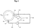
- FIG. 2 shows a schematic view of a laundry care appliance with a pumping system. That in the 2 illustrated pumping system of the laundry care appliance 100 comprises a laundry drum 117 for receiving laundry, a tub 119 for receiving washing liquid, which has a drain opening 121, and wherein the laundry care appliance 100 has an inlet nozzle 123.
- the inlet nozzle 123 and the drain opening 121 are fluidically connected by a line 125, with a pump 127 being arranged in the line 125, which is designed to pump washing liquid through the drain opening 121 from the tub 119 into the line 125 and to pump out the washing liquid that has been pumped out to the line 125 through the inlet nozzle 123 of the laundry drum 117 .
- a drum drive 129 is also shown, which is designed to drive the laundry drum 117 via a drive connection 131.
- the laundry care appliance 100 has a controller 133 which is connected to the drum drive 129 by a first control connection 135 and to the pump 127 by a second control connection 137 .
- the washing liquid injected into the laundry drum 117 through the inlet nozzle 123 can bounce off the laundry, blocking access to the inside of the laundry tunnel, and the washing liquid can run back into the tub 119 without completely flooding the laundry .
- the laundry drum 117 rotates very quickly, the laundry is pressed against the laundry drum 117 due to the centrifugal forces that occur, as a result of which a laundry tunnel is formed in the laundry drum 117 .
- the washing liquid is pumped by the pump 127 through the line 125 to the inlet nozzle 123 . It must then be ensured that the washing liquid pumped out through the inlet nozzle 123 advantageously hits the washing tunnel of the washing in the rotating washing drum 117 . It can thereby be ensured that due to the centrifugal forces that occur, the laundry in the laundry drum 117 is advantageously flooded in a radial direction directed outwards from the laundry tunnel, from the inside to the outside.
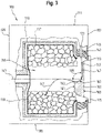
- FIG. 3 shows a schematic view of a laundry care appliance with a laundry drum and a diverting device.
- the representation chosen shows a lateral longitudinal section of a laundry care appliance 100 in the loaded state during the pump-over-injection process.
- In 3 is the top of the device 111, the back of the device 105, the front of the device 103 and the bottom of the device 109 of the Laundry care appliance 100 shown.
- a device loading opening 113 is arranged on the front side 103 of the device, which can be closed by a device door 115, through which the interior of the laundry care device 100 is accessible for loading.
- a suds container 119 for holding the washing liquid and a laundry drum 117 for holding laundry 139 are arranged in the interior of the laundry care appliance 100 , with the laundry drum 117 being rotatable along an axis of rotation 141 .
- the axis of rotation 141 extends from the front side 103 to the rear side 105 of the laundry care appliance 100.
- a sleeve 143 is arranged between the laundry drum 117, the tub 119 and the appliance door 115.
- the sleeve 143 ensures a fluid-technical seal between the laundry drum 117 or the tub 119 and an appliance housing 145 of the laundry care appliance 100 . Furthermore, the sleeve 143 decouples the oscillating system, which is mounted on spring dampers, from the stationary device housing 145.
- An inlet nozzle 123 is arranged on the stationary section of the sleeve 143, which is designed to direct washing liquid 147 pumped out of the inlet nozzle 123 along an injection axis 149 to a diverting device 151 , wherein the deflection device 151 is designed in particular as a bent or curved metal plate, rubber plate, plastic plate or as a bent or curved window glass section and/or as in 3 shown is formed on an inner side 153 of the appliance door 115 .
- the diverting device 151 is arranged on the inside 153 of the appliance door 115 and is designed to divert the washing liquid 147 impinging on the diverting device 151 in the direction of the laundry drum 117, in particular parallel to the axis of rotation 141, and to divert the diverted washing liquid 147 along the axis of rotation 141 into the laundry tunnel 155 in of the laundry drum 117 to inject.
- the diverted washing liquid 147 is introduced, in particular from the front side 103 of the appliance, into a washing tunnel 155 of the washing 139 lying against the washing drum 117 .
- the diverting device 151 has a curved diverting surface 157 against which the washing liquid 147 impinging on the diverting device 151 can be sprayed in order to direct the washing liquid 147 in the direction of the laundry drum 117, in particular parallel to the Axis of rotation 114 redirect.
- the deflection surface 157 is designed in particular as a bent or curved deflection surface 157 .
- the injection axis 149 encloses a deflection angle 159 of 75° to 105°, in particular of 90°, with the axis of rotation 141 of the laundry drum 117 in order to achieve axis-parallel laundry tunnel 155 injection .
- the diverting device 151 can have a profiled surface structure, in particular a depression, groove or rib. In order to ensure an effective bundling of the diverted washing liquid 147, the diverting device 151 can have a bundling element, in particular a bundling nozzle or a bundling nozzle section.
- a protruding edge 163 of the deflection device 151 is arranged on a side 161 of the deflection device 151 that faces the laundry drum 117 .
- the deflection device 151 has, in particular, a progressive incline at the projection edge 163 .
- the protruding edge 163 ensures that, in the event of a reduced pump pressure and a resulting reduced injection pressure of the injected washing liquid 147, the washing liquid 147 does not flow downwards on the side 161 of the diverting device 151 facing the washing drum 117, without effectively closing the washing 139 in the washing drum 117 wet
- the protruding edge 163 and in particular the progressive gradient of the deflection device 151 at the protruding edge 163 ensures that the jet of washing liquid, when flowing over the protruding edge 163, detaches itself from the deflection device 151 and can be effectively directed along the axis of rotation 141 of the laundry drum 117 into the laundry drum 117.
- the diverting device 151 arranged on the inside 153 of the appliance door 115 is used directly for introducing the washing liquid 147 into the laundry 139 .
- the washing liquid jet is deflected by the surface contour of the deflection device 151 .
- the washing liquid 147 can first be injected radially into the center of the tub 119 and then deflected by approximately 90° at the deflection device 151 in order to distribute the deflected washing liquid 147, in particular along the axis of rotation 141 of the laundry drum 117, in particular parallel to the axis of rotation 141 or axially congruent to inject.
- the injection jet deflection can be achieved with conventional diagonal injection from the cuff edge on a straight, semi-axial path into the laundry tunnel 155 by the rotating laundry ring can be avoided completely, because the appliance door 115 continues to fulfill its task in the radially outer areas to keep the laundry 139 away from the cuff 143, but in the central area it can Deflection of the injection jet of the pump-over system by the wash liquor.
- the geometric design of the original injection corridor between the appliance door 115, sleeve 143, tub 119, laundry drum 117 and rotating laundry ring therefore no longer has any influence on the function of wetting or permeating the laundry.
- the deflection device 151 of the appliance door 113 can be used not only for deflecting the injection washing liquid jet, but also for the geometric design of the jet pattern. For example, a so-called fan beam or a point-focused beam can be realized through the design of the deflection device 151.
- the washing mesh phase can be accelerated or textiles that are particularly gentle can be dealt with.
- the detachment of the jet of washing liquid at the deflection device 151 can be implemented by the projecting edge 163 , in which the gradient progresses progressively, so that the washing liquid 147 is reliably detached at the final projecting edge 163 .
- the diverting device 151 enables washing liquid 147 to be injected independently of the load, with which it is always ensured that the injection jet is not impeded or interrupted either by the geometry of the items to be washed, in particular a laundry ring, or by the geometry of the window. In this way, the necessary washing liquid 147 for remoistening and flooding the laundry 139 along the axis of rotation 141 can always be added to the oscillating system in a functionally appropriate manner.
- the design of the washing liquid jet can be influenced at the same time as the injection jet is deflected at the appliance door 115. In this way, not only the location but also the area where the injection occurs in the laundry ring can be influenced. In addition, this also affects the jet intensity, because a fanned-out jet represents, for example, less tissue stress on the laundry due to the impact of the jet of washing liquid.
- the injection process can be visualized for the user by the jet deflection on the door geometry if the appliance door is implemented as usual with a sight glass.
- a drum interior light which is provided on the same sleeve section as the deflection device 151, can further clarify the activity of the injection process, because the light cone and the injection jet are inclined or aligned with the same orientation towards the center of the drum.
- the appliance door 115 has an outer side 165, which is 4 non-illustrated outside area of the laundry care appliance 100 faces.
- the appliance door 115 has an inner side 153, which has an 4 non-illustrated laundry drum 117 of the laundry care appliance 100 faces.
- diverting device 151 On the inside 153 of the appliance door 115 there is an exemplary diverting device 151 which is designed to divert washing liquid 147 hitting the diverting device 151 parallel to the axis of rotation 141 in the direction of the laundry drum 117 of the laundry care appliance 100 .
- the diverting device 151 is formed on the inside 153 of the appliance door 115 .
- Diverting device 151 has a diverting surface 157, against which washing liquid 147 impinging on diverting device 151 can be sprayed in order to divert washing liquid 147 in the direction of laundry drum 117 parallel to axis of rotation 141, diverting surface 157 being a curved or curved diverting surface 157 is trained.
- the diverting device 151 has a projection edge 163 on a side 161 of the diverting device 151 facing the laundry drum 117 , which is designed to direct the diverted washing liquid 147 in the direction of the laundry drum 117 .
- the deflection device 151 at the projection edge 163 has, in particular, a progressive gradient.
- FIG 5 shows a sequence of a method for wetting laundry in a laundry drum, a laundry care appliance, the laundry care appliance according to FIG 3 is described.
- the method 200 comprises as a method step the routing 201 of the washing liquid 147 pumped by the pump 127 through the inlet nozzle 123 onto the diverting device 151 radially to the axis of rotation 141 and the diverting 203 of the washing liquid 147 impinging on the diverting device 151 in the direction of the laundry drum 117, around the diverted Inject washing liquid 147 parallel to the axis of rotation 141 into the laundry drum 117 .
Landscapes
- Engineering & Computer Science (AREA)
- Textile Engineering (AREA)
- Main Body Construction Of Washing Machines And Laundry Dryers (AREA)
- Detail Structures Of Washing Machines And Dryers (AREA)
- Accessory Of Washing/Drying Machine, Commercial Washing/Drying Machine, Other Washing/Drying Machine (AREA)
Applications Claiming Priority (1)
| Application Number | Priority Date | Filing Date | Title |
|---|---|---|---|
| DE102016216391.4A DE102016216391A1 (de) | 2016-08-31 | 2016-08-31 | Wäschepflegegerät mit einer Umleitvorrichtung |
Publications (2)
| Publication Number | Publication Date |
|---|---|
| EP3290572A1 EP3290572A1 (de) | 2018-03-07 |
| EP3290572B1 true EP3290572B1 (de) | 2022-11-02 |
Family
ID=59631654
Family Applications (1)
| Application Number | Title | Priority Date | Filing Date |
|---|---|---|---|
| EP17186383.0A Active EP3290572B1 (de) | 2016-08-31 | 2017-08-16 | Wäschepflegegerät mit einer umleitvorrichtung |
Country Status (4)
| Country | Link |
|---|---|
| EP (1) | EP3290572B1 (pl) |
| CN (1) | CN107794721B (pl) |
| DE (1) | DE102016216391A1 (pl) |
| PL (1) | PL3290572T3 (pl) |
Families Citing this family (14)
| Publication number | Priority date | Publication date | Assignee | Title |
|---|---|---|---|---|
| CN110387713A (zh) * | 2018-04-16 | 2019-10-29 | 青岛海尔滚筒洗衣机有限公司 | 滚筒洗衣机及其喷淋系统 |
| CN110387707B (zh) * | 2018-04-16 | 2021-12-03 | 青岛海尔洗涤电器有限公司 | 滚筒洗衣机及其门体和喷淋系统 |
| CN110644203A (zh) * | 2018-06-26 | 2020-01-03 | 苏州三星电子有限公司 | 洗衣机门体结构及洗衣机 |
| CN109112763A (zh) * | 2018-10-17 | 2019-01-01 | 宁波新乐电器有限公司 | 一种具有喷淋结构的滚筒洗衣机 |
| EP3741907B1 (en) * | 2019-05-23 | 2023-06-07 | Whirlpool Corporation | Laundry appliance |
| CN117888337A (zh) | 2019-05-23 | 2024-04-16 | 惠而浦公司 | 洗衣设备 |
| US11377772B2 (en) | 2019-05-23 | 2022-07-05 | Whirlpool Corporation | Laundry appliance |
| US11761134B2 (en) | 2019-05-23 | 2023-09-19 | Whirlpool Corporation | Laundry appliance |
| DE102019212838A1 (de) * | 2019-08-27 | 2021-03-04 | BSH Hausgeräte GmbH | Anordnung zum Steuern einer Austrittsrichtung eines Fluids |
| DE102019213017A1 (de) * | 2019-08-29 | 2021-03-04 | BSH Hausgeräte GmbH | Wäschepflegegerät mit einer Steuerung |
| DE102019213015A1 (de) | 2019-08-29 | 2021-03-04 | BSH Hausgeräte GmbH | Wäschepflegegerät mit einer Steuerung |
| DE102019213014A1 (de) * | 2019-08-29 | 2021-03-04 | BSH Hausgeräte GmbH | Wäschepflegegerät mit einer Steuerung |
| US11725331B2 (en) | 2020-11-20 | 2023-08-15 | Whirlpool Corporation | Water recirculation assembly for a laundry appliance |
| EP4047117B1 (de) * | 2021-02-19 | 2026-03-25 | Schulthess Maschinen AG | Waschmaschine mit umwälzung |
Citations (1)
| Publication number | Priority date | Publication date | Assignee | Title |
|---|---|---|---|---|
| CN202116872U (zh) * | 2011-06-01 | 2012-01-18 | 无锡小天鹅通用电器有限公司 | 具有门玻璃自清洗功能的滚筒洗衣机 |
Family Cites Families (15)
| Publication number | Priority date | Publication date | Assignee | Title |
|---|---|---|---|---|
| DE3811582A1 (de) * | 1988-04-07 | 1989-10-19 | Licentia Gmbh | Stirnseitig beschickbare trommelwaschmaschine |
| IT1256272B (it) * | 1991-10-22 | 1995-11-29 | Zanussi Elettrodomestici | Lavabiancheria con contenitore detersivo ricavato nell'oblo' |
| IT1259234B (it) * | 1992-11-11 | 1996-03-11 | Zanussi Elettrodomestici | Lavatrici con dispositivo perfezionato di caricamento d'acqua |
| DE4330079C2 (de) | 1993-09-06 | 2000-05-11 | Bsh Bosch Siemens Hausgeraete | Frontseitig beschickbare Trommelwaschmaschine |
| CN2372345Y (zh) * | 1999-05-12 | 2000-04-05 | 海尔集团公司 | 滚筒洗衣机的喷淋装置 |
| DE102004043671B4 (de) * | 2004-09-07 | 2008-04-10 | Miele & Cie. Kg | Frontbeschickbare Trommelwaschmaschine mit Wäscheabweiser an der Faltenbalgdichtung |
| DE102006003416A1 (de) * | 2006-01-24 | 2007-07-26 | BSH Bosch und Siemens Hausgeräte GmbH | Haushalt-Waschmaschine mit einer drehbar gelagerten Wäschetrommel und Verfahren zum Deodorieren von Kleidung in einer solchen Waschmaschine |
| KR101257703B1 (ko) * | 2006-04-13 | 2013-04-24 | 삼성전자주식회사 | 드럼세탁기 |
| JP2009006081A (ja) * | 2007-06-29 | 2009-01-15 | Toshiba Corp | 洗濯機 |
| KR20090107164A (ko) * | 2008-04-08 | 2009-10-13 | 엘지전자 주식회사 | 세탁기 |
| US8661860B2 (en) | 2009-07-31 | 2014-03-04 | Bsh Home Appliances Corporation | Door bowl for a household appliance door |
| KR101635873B1 (ko) * | 2009-09-04 | 2016-07-20 | 엘지전자 주식회사 | 세탁장치 |
| JP5873968B2 (ja) * | 2011-09-05 | 2016-03-01 | パナソニックIpマネジメント株式会社 | 洗濯機 |
| US9115461B2 (en) * | 2011-12-21 | 2015-08-25 | Whirlpool Corporation | Door wash aid dispenser for a laundry treating appliance |
| DE102013106097B4 (de) | 2013-06-12 | 2022-03-17 | Miele & Cie. Kg | Verfahren zum Betreiben einer Waschmaschine und Waschmaschine |
-
2016
- 2016-08-31 DE DE102016216391.4A patent/DE102016216391A1/de not_active Withdrawn
-
2017
- 2017-08-16 PL PL17186383.0T patent/PL3290572T3/pl unknown
- 2017-08-16 EP EP17186383.0A patent/EP3290572B1/de active Active
- 2017-08-30 CN CN201710762703.1A patent/CN107794721B/zh active Active
Patent Citations (1)
| Publication number | Priority date | Publication date | Assignee | Title |
|---|---|---|---|---|
| CN202116872U (zh) * | 2011-06-01 | 2012-01-18 | 无锡小天鹅通用电器有限公司 | 具有门玻璃自清洗功能的滚筒洗衣机 |
Also Published As
| Publication number | Publication date |
|---|---|
| DE102016216391A1 (de) | 2018-03-01 |
| CN107794721A (zh) | 2018-03-13 |
| PL3290572T3 (pl) | 2023-01-16 |
| EP3290572A1 (de) | 2018-03-07 |
| CN107794721B (zh) | 2021-07-27 |
Similar Documents
| Publication | Publication Date | Title |
|---|---|---|
| EP3290572B1 (de) | Wäschepflegegerät mit einer umleitvorrichtung | |
| DE60317274T2 (de) | Waschmaschine | |
| EP2404539B1 (de) | Wasserweiche für ein wasserführendes Haushaltsgerät | |
| DE10227863B4 (de) | Trommelwaschmaschine | |
| EP2140056B1 (de) | Wäscheabweiservorrichtung für ein hausgerät zur pflege von wäschestücken sowie ein derartiges hausgerät | |
| DE10245216A1 (de) | Trommelwaschmaschine | |
| EP3332059B1 (de) | Wäschepflegegerät mit einem zirkulationssystem | |
| EP3613891B1 (de) | Wäschepflegegerät mit einer einlassdüse | |
| EP2022882B1 (de) | Trommel für eine Waschmaschine und Waschmaschine | |
| EP3443156B1 (de) | Wäschepflegegerät mit einer steuerung | |
| EP2348152B1 (de) | Waschmaschine mit Umfluteinrichtung | |
| WO2008000591A1 (de) | Verfahren zum einbringen von waschmitteln und waschmaschine dafür | |
| EP1643028A1 (de) | Laugenbehälter für eine Waschmaschine | |
| EP2821539B1 (de) | Trommelwaschmaschine mit Unwuchtausgleich und Umflutung | |
| EP1375727B1 (de) | Waschmaschine | |
| DE102008035790B4 (de) | Trommelwaschmaschine | |
| EP4324973A1 (de) | Haushaltsgerät zur pflege von wäschestücken mit spezifischem spülsystem für ein luftleitsystem, sowie verfahren | |
| DE842189C (de) | Maschine zum Waschen und Schleudern von Waesche | |
| EP2933366A1 (de) | Verfahren zum betreiben einer waschmaschine mit umfluteinrichtung | |
| EP4053323B1 (de) | Waschmaschine mit umpumpsystem und verfahren zu deren betrieb | |
| DE102019204757B4 (de) | Waschmaschine | |
| DE102018112923A1 (de) | Waschtrommel und Waschautomat | |
| EP4127293A1 (de) | Verfahren und waschautomat | |
| DE10132199C1 (de) | Verfahren zum Schleudern von Wäsche | |
| EP4375409A1 (de) | Wäschepflegegerät mit einer steuerung |
Legal Events
| Date | Code | Title | Description |
|---|---|---|---|
| PUAI | Public reference made under article 153(3) epc to a published international application that has entered the european phase |
Free format text: ORIGINAL CODE: 0009012 |
|
| STAA | Information on the status of an ep patent application or granted ep patent |
Free format text: STATUS: THE APPLICATION HAS BEEN PUBLISHED |
|
| AK | Designated contracting states |
Kind code of ref document: A1 Designated state(s): AL AT BE BG CH CY CZ DE DK EE ES FI FR GB GR HR HU IE IS IT LI LT LU LV MC MK MT NL NO PL PT RO RS SE SI SK SM TR |
|
| AX | Request for extension of the european patent |
Extension state: BA ME |
|
| STAA | Information on the status of an ep patent application or granted ep patent |
Free format text: STATUS: REQUEST FOR EXAMINATION WAS MADE |
|
| 17P | Request for examination filed |
Effective date: 20180907 |
|
| RBV | Designated contracting states (corrected) |
Designated state(s): AL AT BE BG CH CY CZ DE DK EE ES FI FR GB GR HR HU IE IS IT LI LT LU LV MC MK MT NL NO PL PT RO RS SE SI SK SM TR |
|
| STAA | Information on the status of an ep patent application or granted ep patent |
Free format text: STATUS: EXAMINATION IS IN PROGRESS |
|
| 17Q | First examination report despatched |
Effective date: 20210528 |
|
| GRAP | Despatch of communication of intention to grant a patent |
Free format text: ORIGINAL CODE: EPIDOSNIGR1 |
|
| STAA | Information on the status of an ep patent application or granted ep patent |
Free format text: STATUS: GRANT OF PATENT IS INTENDED |
|
| RIC1 | Information provided on ipc code assigned before grant |
Ipc: D06F 37/26 20060101ALN20220518BHEP Ipc: D06F 37/30 20060101ALN20220518BHEP Ipc: D06F 39/14 20060101ALI20220518BHEP Ipc: D06F 39/08 20060101AFI20220518BHEP |
|
| RIC1 | Information provided on ipc code assigned before grant |
Ipc: D06F 37/26 20060101ALN20220603BHEP Ipc: D06F 37/30 20060101ALN20220603BHEP Ipc: D06F 39/14 20060101ALI20220603BHEP Ipc: D06F 39/08 20060101AFI20220603BHEP |
|
| INTG | Intention to grant announced |
Effective date: 20220621 |
|
| GRAS | Grant fee paid |
Free format text: ORIGINAL CODE: EPIDOSNIGR3 |
|
| GRAA | (expected) grant |
Free format text: ORIGINAL CODE: 0009210 |
|
| STAA | Information on the status of an ep patent application or granted ep patent |
Free format text: STATUS: THE PATENT HAS BEEN GRANTED |
|
| AK | Designated contracting states |
Kind code of ref document: B1 Designated state(s): AL AT BE BG CH CY CZ DE DK EE ES FI FR GB GR HR HU IE IS IT LI LT LU LV MC MK MT NL NO PL PT RO RS SE SI SK SM TR |
|
| REG | Reference to a national code |
Ref country code: GB Ref legal event code: FG4D Free format text: NOT ENGLISH |
|
| REG | Reference to a national code |
Ref country code: CH Ref legal event code: EP Ref country code: AT Ref legal event code: REF Ref document number: 1528816 Country of ref document: AT Kind code of ref document: T Effective date: 20221115 |
|
| REG | Reference to a national code |
Ref country code: DE Ref legal event code: R096 Ref document number: 502017014025 Country of ref document: DE |
|
| REG | Reference to a national code |
Ref country code: IE Ref legal event code: FG4D Free format text: LANGUAGE OF EP DOCUMENT: GERMAN |
|
| REG | Reference to a national code |
Ref country code: DE Ref legal event code: R084 Ref document number: 502017014025 Country of ref document: DE |
|
| REG | Reference to a national code |
Ref country code: LT Ref legal event code: MG9D |
|
| REG | Reference to a national code |
Ref country code: NL Ref legal event code: MP Effective date: 20221102 |
|
| PG25 | Lapsed in a contracting state [announced via postgrant information from national office to epo] |
Ref country code: SE Free format text: LAPSE BECAUSE OF FAILURE TO SUBMIT A TRANSLATION OF THE DESCRIPTION OR TO PAY THE FEE WITHIN THE PRESCRIBED TIME-LIMIT Effective date: 20221102 Ref country code: PT Free format text: LAPSE BECAUSE OF FAILURE TO SUBMIT A TRANSLATION OF THE DESCRIPTION OR TO PAY THE FEE WITHIN THE PRESCRIBED TIME-LIMIT Effective date: 20230302 Ref country code: NO Free format text: LAPSE BECAUSE OF FAILURE TO SUBMIT A TRANSLATION OF THE DESCRIPTION OR TO PAY THE FEE WITHIN THE PRESCRIBED TIME-LIMIT Effective date: 20230202 Ref country code: LT Free format text: LAPSE BECAUSE OF FAILURE TO SUBMIT A TRANSLATION OF THE DESCRIPTION OR TO PAY THE FEE WITHIN THE PRESCRIBED TIME-LIMIT Effective date: 20221102 Ref country code: FI Free format text: LAPSE BECAUSE OF FAILURE TO SUBMIT A TRANSLATION OF THE DESCRIPTION OR TO PAY THE FEE WITHIN THE PRESCRIBED TIME-LIMIT Effective date: 20221102 Ref country code: ES Free format text: LAPSE BECAUSE OF FAILURE TO SUBMIT A TRANSLATION OF THE DESCRIPTION OR TO PAY THE FEE WITHIN THE PRESCRIBED TIME-LIMIT Effective date: 20221102 |
|
| PG25 | Lapsed in a contracting state [announced via postgrant information from national office to epo] |
Ref country code: RS Free format text: LAPSE BECAUSE OF FAILURE TO SUBMIT A TRANSLATION OF THE DESCRIPTION OR TO PAY THE FEE WITHIN THE PRESCRIBED TIME-LIMIT Effective date: 20221102 Ref country code: LV Free format text: LAPSE BECAUSE OF FAILURE TO SUBMIT A TRANSLATION OF THE DESCRIPTION OR TO PAY THE FEE WITHIN THE PRESCRIBED TIME-LIMIT Effective date: 20221102 Ref country code: IS Free format text: LAPSE BECAUSE OF FAILURE TO SUBMIT A TRANSLATION OF THE DESCRIPTION OR TO PAY THE FEE WITHIN THE PRESCRIBED TIME-LIMIT Effective date: 20230302 Ref country code: HR Free format text: LAPSE BECAUSE OF FAILURE TO SUBMIT A TRANSLATION OF THE DESCRIPTION OR TO PAY THE FEE WITHIN THE PRESCRIBED TIME-LIMIT Effective date: 20221102 Ref country code: GR Free format text: LAPSE BECAUSE OF FAILURE TO SUBMIT A TRANSLATION OF THE DESCRIPTION OR TO PAY THE FEE WITHIN THE PRESCRIBED TIME-LIMIT Effective date: 20230203 |
|
| PG25 | Lapsed in a contracting state [announced via postgrant information from national office to epo] |
Ref country code: NL Free format text: LAPSE BECAUSE OF FAILURE TO SUBMIT A TRANSLATION OF THE DESCRIPTION OR TO PAY THE FEE WITHIN THE PRESCRIBED TIME-LIMIT Effective date: 20221102 |
|
| PG25 | Lapsed in a contracting state [announced via postgrant information from national office to epo] |
Ref country code: SM Free format text: LAPSE BECAUSE OF FAILURE TO SUBMIT A TRANSLATION OF THE DESCRIPTION OR TO PAY THE FEE WITHIN THE PRESCRIBED TIME-LIMIT Effective date: 20221102 Ref country code: RO Free format text: LAPSE BECAUSE OF FAILURE TO SUBMIT A TRANSLATION OF THE DESCRIPTION OR TO PAY THE FEE WITHIN THE PRESCRIBED TIME-LIMIT Effective date: 20221102 Ref country code: EE Free format text: LAPSE BECAUSE OF FAILURE TO SUBMIT A TRANSLATION OF THE DESCRIPTION OR TO PAY THE FEE WITHIN THE PRESCRIBED TIME-LIMIT Effective date: 20221102 Ref country code: DK Free format text: LAPSE BECAUSE OF FAILURE TO SUBMIT A TRANSLATION OF THE DESCRIPTION OR TO PAY THE FEE WITHIN THE PRESCRIBED TIME-LIMIT Effective date: 20221102 Ref country code: CZ Free format text: LAPSE BECAUSE OF FAILURE TO SUBMIT A TRANSLATION OF THE DESCRIPTION OR TO PAY THE FEE WITHIN THE PRESCRIBED TIME-LIMIT Effective date: 20221102 |
|
| REG | Reference to a national code |
Ref country code: DE Ref legal event code: R097 Ref document number: 502017014025 Country of ref document: DE |
|
| PG25 | Lapsed in a contracting state [announced via postgrant information from national office to epo] |
Ref country code: SK Free format text: LAPSE BECAUSE OF FAILURE TO SUBMIT A TRANSLATION OF THE DESCRIPTION OR TO PAY THE FEE WITHIN THE PRESCRIBED TIME-LIMIT Effective date: 20221102 Ref country code: AL Free format text: LAPSE BECAUSE OF FAILURE TO SUBMIT A TRANSLATION OF THE DESCRIPTION OR TO PAY THE FEE WITHIN THE PRESCRIBED TIME-LIMIT Effective date: 20221102 |
|
| PLBE | No opposition filed within time limit |
Free format text: ORIGINAL CODE: 0009261 |
|
| STAA | Information on the status of an ep patent application or granted ep patent |
Free format text: STATUS: NO OPPOSITION FILED WITHIN TIME LIMIT |
|
| 26N | No opposition filed |
Effective date: 20230803 |
|
| PG25 | Lapsed in a contracting state [announced via postgrant information from national office to epo] |
Ref country code: SI Free format text: LAPSE BECAUSE OF FAILURE TO SUBMIT A TRANSLATION OF THE DESCRIPTION OR TO PAY THE FEE WITHIN THE PRESCRIBED TIME-LIMIT Effective date: 20221102 |
|
| PG25 | Lapsed in a contracting state [announced via postgrant information from national office to epo] |
Ref country code: MC Free format text: LAPSE BECAUSE OF FAILURE TO SUBMIT A TRANSLATION OF THE DESCRIPTION OR TO PAY THE FEE WITHIN THE PRESCRIBED TIME-LIMIT Effective date: 20221102 |
|
| REG | Reference to a national code |
Ref country code: CH Ref legal event code: PL |
|
| PG25 | Lapsed in a contracting state [announced via postgrant information from national office to epo] |
Ref country code: MC Free format text: LAPSE BECAUSE OF FAILURE TO SUBMIT A TRANSLATION OF THE DESCRIPTION OR TO PAY THE FEE WITHIN THE PRESCRIBED TIME-LIMIT Effective date: 20221102 |
|
| PG25 | Lapsed in a contracting state [announced via postgrant information from national office to epo] |
Ref country code: LU Free format text: LAPSE BECAUSE OF NON-PAYMENT OF DUE FEES Effective date: 20230816 |
|
| GBPC | Gb: european patent ceased through non-payment of renewal fee |
Effective date: 20230816 |
|
| PG25 | Lapsed in a contracting state [announced via postgrant information from national office to epo] |
Ref country code: LU Free format text: LAPSE BECAUSE OF NON-PAYMENT OF DUE FEES Effective date: 20230816 Ref country code: CH Free format text: LAPSE BECAUSE OF NON-PAYMENT OF DUE FEES Effective date: 20230831 |
|
| REG | Reference to a national code |
Ref country code: BE Ref legal event code: MM Effective date: 20230831 |
|
| REG | Reference to a national code |
Ref country code: IE Ref legal event code: MM4A |
|
| PG25 | Lapsed in a contracting state [announced via postgrant information from national office to epo] |
Ref country code: IT Free format text: LAPSE BECAUSE OF FAILURE TO SUBMIT A TRANSLATION OF THE DESCRIPTION OR TO PAY THE FEE WITHIN THE PRESCRIBED TIME-LIMIT Effective date: 20221102 |
|
| PG25 | Lapsed in a contracting state [announced via postgrant information from national office to epo] |
Ref country code: IE Free format text: LAPSE BECAUSE OF NON-PAYMENT OF DUE FEES Effective date: 20230816 |
|
| PG25 | Lapsed in a contracting state [announced via postgrant information from national office to epo] |
Ref country code: GB Free format text: LAPSE BECAUSE OF NON-PAYMENT OF DUE FEES Effective date: 20230816 |
|
| PG25 | Lapsed in a contracting state [announced via postgrant information from national office to epo] |
Ref country code: IE Free format text: LAPSE BECAUSE OF NON-PAYMENT OF DUE FEES Effective date: 20230816 Ref country code: GB Free format text: LAPSE BECAUSE OF NON-PAYMENT OF DUE FEES Effective date: 20230816 Ref country code: FR Free format text: LAPSE BECAUSE OF NON-PAYMENT OF DUE FEES Effective date: 20230831 |
|
| PG25 | Lapsed in a contracting state [announced via postgrant information from national office to epo] |
Ref country code: BE Free format text: LAPSE BECAUSE OF NON-PAYMENT OF DUE FEES Effective date: 20230831 |
|
| REG | Reference to a national code |
Ref country code: AT Ref legal event code: MM01 Ref document number: 1528816 Country of ref document: AT Kind code of ref document: T Effective date: 20230816 |
|
| PG25 | Lapsed in a contracting state [announced via postgrant information from national office to epo] |
Ref country code: AT Free format text: LAPSE BECAUSE OF NON-PAYMENT OF DUE FEES Effective date: 20230816 |
|
| PGFP | Annual fee paid to national office [announced via postgrant information from national office to epo] |
Ref country code: PL Payment date: 20240807 Year of fee payment: 8 |
|
| PG25 | Lapsed in a contracting state [announced via postgrant information from national office to epo] |
Ref country code: AT Free format text: LAPSE BECAUSE OF NON-PAYMENT OF DUE FEES Effective date: 20230816 |
|
| PG25 | Lapsed in a contracting state [announced via postgrant information from national office to epo] |
Ref country code: BG Free format text: LAPSE BECAUSE OF FAILURE TO SUBMIT A TRANSLATION OF THE DESCRIPTION OR TO PAY THE FEE WITHIN THE PRESCRIBED TIME-LIMIT Effective date: 20221102 |
|
| PG25 | Lapsed in a contracting state [announced via postgrant information from national office to epo] |
Ref country code: BG Free format text: LAPSE BECAUSE OF FAILURE TO SUBMIT A TRANSLATION OF THE DESCRIPTION OR TO PAY THE FEE WITHIN THE PRESCRIBED TIME-LIMIT Effective date: 20221102 |
|
| PG25 | Lapsed in a contracting state [announced via postgrant information from national office to epo] |
Ref country code: CY Free format text: LAPSE BECAUSE OF FAILURE TO SUBMIT A TRANSLATION OF THE DESCRIPTION OR TO PAY THE FEE WITHIN THE PRESCRIBED TIME-LIMIT; INVALID AB INITIO Effective date: 20170816 |
|
| PG25 | Lapsed in a contracting state [announced via postgrant information from national office to epo] |
Ref country code: HU Free format text: LAPSE BECAUSE OF FAILURE TO SUBMIT A TRANSLATION OF THE DESCRIPTION OR TO PAY THE FEE WITHIN THE PRESCRIBED TIME-LIMIT; INVALID AB INITIO Effective date: 20170816 |
|
| PGFP | Annual fee paid to national office [announced via postgrant information from national office to epo] |
Ref country code: DE Payment date: 20250831 Year of fee payment: 9 |
|
| PGFP | Annual fee paid to national office [announced via postgrant information from national office to epo] |
Ref country code: TR Payment date: 20250808 Year of fee payment: 9 |