EP3290552B1 - Rouleau à godet - Google Patents
Rouleau à godet Download PDFInfo
- Publication number
- EP3290552B1 EP3290552B1 EP16785887.7A EP16785887A EP3290552B1 EP 3290552 B1 EP3290552 B1 EP 3290552B1 EP 16785887 A EP16785887 A EP 16785887A EP 3290552 B1 EP3290552 B1 EP 3290552B1
- Authority
- EP
- European Patent Office
- Prior art keywords
- roller bearing
- sleeve
- connecting sleeve
- shaft
- screw
- Prior art date
- Legal status (The legal status is an assumption and is not a legal conclusion. Google has not performed a legal analysis and makes no representation as to the accuracy of the status listed.)
- Active
Links
Images
Classifications
-
- D—TEXTILES; PAPER
- D01—NATURAL OR MAN-MADE THREADS OR FIBRES; SPINNING
- D01H—SPINNING OR TWISTING
- D01H13/00—Other common constructional features, details or accessories
- D01H13/02—Roller arrangements not otherwise provided for
-
- B—PERFORMING OPERATIONS; TRANSPORTING
- B65—CONVEYING; PACKING; STORING; HANDLING THIN OR FILAMENTARY MATERIAL
- B65H—HANDLING THIN OR FILAMENTARY MATERIAL, e.g. SHEETS, WEBS, CABLES
- B65H57/00—Guides for filamentary materials; Supports therefor
- B65H57/14—Pulleys, rollers, or rotary bars
-
- D—TEXTILES; PAPER
- D02—YARNS; MECHANICAL FINISHING OF YARNS OR ROPES; WARPING OR BEAMING
- D02J—FINISHING OR DRESSING OF FILAMENTS, YARNS, THREADS, CORDS, ROPES OR THE LIKE
- D02J1/00—Modifying the structure or properties resulting from a particular structure; Modifying, retaining, or restoring the physical form or cross-sectional shape, e.g. by use of dies or squeeze rollers
- D02J1/22—Stretching or tensioning, shrinking or relaxing, e.g. by use of overfeed and underfeed apparatus, or preventing stretch
-
- F—MECHANICAL ENGINEERING; LIGHTING; HEATING; WEAPONS; BLASTING
- F16—ENGINEERING ELEMENTS AND UNITS; GENERAL MEASURES FOR PRODUCING AND MAINTAINING EFFECTIVE FUNCTIONING OF MACHINES OR INSTALLATIONS; THERMAL INSULATION IN GENERAL
- F16C—SHAFTS; FLEXIBLE SHAFTS; ELEMENTS OR CRANKSHAFT MECHANISMS; ROTARY BODIES OTHER THAN GEARING ELEMENTS; BEARINGS
- F16C19/00—Bearings with rolling contact, for exclusively rotary movement
-
- B—PERFORMING OPERATIONS; TRANSPORTING
- B65—CONVEYING; PACKING; STORING; HANDLING THIN OR FILAMENTARY MATERIAL
- B65H—HANDLING THIN OR FILAMENTARY MATERIAL, e.g. SHEETS, WEBS, CABLES
- B65H2701/00—Handled material; Storage means
- B65H2701/30—Handled filamentary material
- B65H2701/31—Textiles threads or artificial strands of filaments
Definitions
- the present invention relates to the technical field of textile manufacturing machines, and it can particularly advantageously be implemented on a thread guide roller.
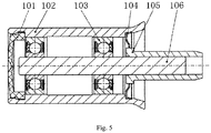
- ( CN204151507U ) are, as in Figure 5 shown, two roller bearings 103 are arranged between a shaft 106 and a bush 102, the roller bearing 103 being, for example, a ball bearing. There is an interference fit between the shaft 106 and the inner ring of the roller bearing 103, as well as between the bush 102 and the outer ring of the roller bearing 103.
- a cover 101 and a sealing ring 104 are each mounted in a groove of the bush 102.
- the connecting sleeve 105 is press-fitted onto the shaft 106.
- the cover 101 can be made of plastic and the sealing ring 104 can be made of steel.
- a yarn is wound on the outer peripheral surface of the bush 102.
- the bush 102 rotates in the circumferential direction while being carried along by the yarn. Since there is an interference fit between the bush 102 and the outer ring of the rolling bearing 103, the outer ring of the rolling bearing 103 rotates while being driven by the bush 102.
- the shaft 106 and the connecting sleeve 105 do not move between the shaft 106 and the inner ring of the rolling bearing 103 there is an interference fit, the inner ring of the rolling bearing 103 does not rotate with the bush 102.
- the present invention is based on the object of solving the above-mentioned problems of the prior art and of providing a thread guide roller with which a simple structure, simple assembly and / or disassembly, rotation of the inner ring of the rolling bearing, simple repair and / or Exchange and reusability of the component can be achieved.
- a thread guide roller comprising a cylindrical sleeve which can rotate while being carried along by an external thread; a shaft fixed with respect to the rotation of the sleeve; and a roller bearing arranged inside the bushing, the thread guide roller also comprising a connecting sleeve and a connecting part, the connecting sleeve being connected to the inner surface of the bushing so that it can follow the rotation of the bushing
- the connecting sleeve, the roller bearing and the shaft are arranged in the axial direction of the bushing, so that the connecting sleeve and the shaft are each located on the two opposite sides of the roller bearing in the axial direction, the connecting part is guided through the inner ring of the roller bearing and removably connected to the connecting sleeve and the outer ring of the roller bearing is connected to the shaft so that in the not yet connected or disconnected state of the connection of the connecting part to the connecting sleeve by means of the shaft, at least part of the connecting part and the roller bearing can be inserted into or moved
- the connecting part preferably comprises a screw and a screw nut screwed to the screw, the screw nut being arranged in the axial direction of the roller bearing on the side of the screw further away from the shaft and there being a clearance fit between the connecting sleeve and the screw.
- the thread guide roller preferably further comprises a sleeve which is mounted between the bushing and the outer ring of the roller bearing, the outer ring of the roller bearing being connected to the shaft via the sleeve.
- a concave groove is arranged on the inner surface of the sleeve and a clamping connection ring is mounted in the concave groove, which ring is arranged in the axial direction of the rolling bearing on the side of the rolling bearing further away from the shaft.
- the screw and the screw nut preferably hold the connecting sleeve and the inner ring of the roller bearing closely together in the axial direction of the roller bearing.
- the connecting sleeve preferably comprises a circular plate part and a circular ring part protruding partially in the axial direction on the radial inner side of the circular plate part, the circular ring part resting on the inner ring of the roller bearing.
- the connecting sleeve furthermore comprises a plurality of ribs extending in a radial shape and arranged on the circular plate part.
- the present invention has the advantages that the thread guide roller is easy to dismantle and maintain and, in particular after a defect in the roller bearing, the connecting part and roller bearing can simply be pulled out and replaced together, so that this is avoided that the entire thread guide roller has to be disposed of due to a laborious replacement of the roller bearing, thus saving production costs.
- the inner ring of the roller bearing of the thread guide roller rotates and the outer ring of the roller bearing does not rotate, which is advantageous for the use of a roller bearing with a single protective part. It is not necessary to construct a complicated protective part and top up with oil during maintenance, and a large number of the individual components can be reused.
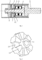
- One embodiment of the present invention relates to a thread guide roller comprising a cylindrical bush 1 which can rotate while being carried along by an external yarn, a shaft 5 fixed with respect to the rotation of the bush 1 and a roller bearing arranged inside the bush 1 3, wherein the thread guide roller further comprises a connecting sleeve 2 and a connecting part, the connecting sleeve 2 is connected to the inner surface of the bush 1 so that it can follow the rotation of the bush 1.
- the connecting sleeve 2, the roller bearing 3 and the shaft 5 are arranged in the axial direction of the bush 1 so that the connecting sleeve 2 and the shaft 5 are each located on the two opposite sides of the roller bearing 3 in the axial direction, the connecting part through the inner ring of the roller bearing 3 is guided and detachably connected to the connecting sleeve 2 and the outer ring of the roller bearing 3 is connected to the shaft 5, so that in the not yet connected or disconnected state of the connection of the connecting part to the connecting sleeve 2 by means of the shaft 5, at least part of the connecting part and the Rolling bearings 3 can be inserted in the axial direction into the socket 1 or moved out of it.
- the bush 1, the connecting sleeve 2, the connecting part and the inner ring of the rolling bearing 3 can rotate together, and the outer ring of the rolling bearing 3 is fixed to the shaft 5.
- the connecting part can first be dismantled from the connecting sleeve 2 or the fastening between the connecting part and the connecting sleeve 2 can be released and then the connecting part and the roller bearing 3 can be pulled out of the socket 1 together.
- the connecting part comprises a screw 7 and a screw nut 8 screwed to the screw 7, the screw nut 8 being arranged in the axial direction of the roller bearing 3 on the side of the screw 7 further away from the shaft 5 and between the connecting sleeve 2 and the screw 7 there is a clearance fit.
- the use of the screw 7 and the screw nut 8 for the connecting part makes the present invention simple in structure and easy to implement.
- the connecting sleeve 2 rotates while being carried along by the bushing 1 and then the screw 7, the screw nut 8 and the inner ring of the roller bearing 3 rotate while being carried along by the connecting sleeve 2
- the bush 1, the connecting sleeve 2, the screw 7, the screw nut 8 and the inner ring of the roller bearing 3 rotate together.
- the thread guide roller further comprises a sleeve 4, the sleeve 4 being mounted between the bush 1 and the outer ring of the roller bearing 3 and the outer ring of the roller bearing 3 being connected to the shaft 5 via the sleeve 4.
- a structure is particularly suitable for connecting the outer ring of the rolling bearing 3 and has the effect that a connection between the shaft 5 and the outer ring of the rolling bearing 3 is formed. It is also suitable for removing the sleeve 4 from the outer ring of the roller bearing 3 after the shaft 5, the sleeve 4, the roller bearing 3 and the screw 7 have been pulled out of the socket 1, for example to replace a defective roller bearing.
- a concave groove 9 is arranged on the inner surface of the sleeve 4 and a clamping connection ring 6 is mounted in the concave groove 9, which is arranged in the axial direction of the rolling bearing 3 on the side of the rolling bearing 3 further away from the shaft 5.
- the function of the clamping connection ring 6 is to additionally hold the roller bearing 3 during regular operation of the thread guide roller and to be able to prevent its displacement in the axial direction and, when the sleeve 4 is pulled out, by the clamping connection ring 6 resting against the roller bearing 3, it also ensures that the roller bearing 3 is moved out together with the sleeve 4.
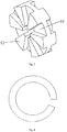
- the clamping connection ring 6 can have a structure as in FIG Figure 4 have shown, ie the clamping connection ring 6 forms approximately a C-shaped circular plate shape.
- the clamping connection ring 6 can be easily mounted in the concave groove 9 of the socket 4 and when the radial compression force acting on the clamping connection ring 6 is subsequently released, the clamping connection ring 6 becomes in the concave groove 9 clamped.
- the radial inside of the clamping connection ring 6 rests partially in the axial direction on the outer ring of the roller bearing 3 and, for example, the inside diameter of the clamping connection ring 6 can be smaller than the outside diameter of the outer ring of the roller bearing 3, thus preventing the outer ring of the roller bearing 3 from moving against the sleeve 4 is moved towards the left end in the figure and that when the shaft 5 is pulled out towards the right end in the figure, the roller bearing 3 and the screw 7 can be pulled out together.
- the radial inner end of the clamping connection ring 6 has no contact with the circular ring part 11 of the connecting sleeve 2, whereby the friction between the two can be eliminated.
- This embodiment is suitable for connecting the shaft 5 to the outer ring of the roller bearing 3 through the sleeve 4 and, after pulling out the shaft 5, the sleeve 4, the roller bearing 3 and the screw 7 from the socket 1, the sleeve 4 is easier to remove To solve the outer ring of the roller bearing 3, for example to replace a defective roller bearing.
- the sleeve 4 there is a press fit between the sleeve 4 and the outer ring of the roller bearing 3.
- the help of a tool may be required to loosen the outer ring of the roller bearing 3 from the sleeve 4, but this can still be ensured that the sleeve 4 can be pulled out in one unit with the roller bearing 3 without having to arrange a clamping connection ring 6 and thus at least one object of the present invention can also be realized.
- the screw 7 and the screw nut 8 hold the connecting sleeve 2 and the inner ring of the roller bearing 3 closely together in the axial direction of the roller bearing 3.
- the pressing of the connecting sleeve 2 and the inner ring of the roller bearing 3 against one another in the axial direction is suitable to prevent a displacement of the roller bearing 3 and the connecting sleeve 2 in the axial direction.
- the connecting sleeve 2 does not usually have to be opened or removed during the maintenance and replacement period, such an arrangement increases the stability of the structure and is better suited to completely transferring the rotational movement of the socket 1 to the connecting sleeve 2.
- the press fit between the screw 7 and the inner ring of the roller bearing 3 is better suited to allow the inner ring of the roller bearing 3 to rotate even better following the rotation of the screw 7.
- the connecting sleeve 2 as in FIG Figure 2 shown, a circular plate part 10 and a circular ring part 11 protruding partially in the axial direction on the radial inside of the circular plate part 10, the circular ring part 11 resting on the inner ring of the roller bearing 3.
- the circular ring part 11 can better guide the extension of the screw 7 in the direction of the roller bearing 3 and the fact that the circular ring part 11 rests against the inner ring of the roller bearing 3 can also prevent displacement of the roller bearing 3 in the axial direction.
- such a structure of the connecting sleeve 2 can ensure that the circular ring part 11 only comes into contact with the inner ring of the roller bearing 3 and not with other parts of the roller bearing (such as the protective part or the outer ring). In this way it can be achieved both that the connecting sleeve 2 rotates together with the inner ring of the roller bearing 3 and that the standstill of the outer ring etc. is not impaired.
- the connecting sleeve 2 furthermore comprises a plurality of radially extending ribs 12 arranged on the circular plate part 10.
- the ribs 12 can additionally increase the strength of the connecting sleeve 2 amplify and generate an air flow during rotation, which helps dissipate heat.
- the connecting sleeve 2 on the side of the connecting sleeve 2 further away from the shaft 5 (the left side in the figure) no circular ring part 11 is formed (the circular ring part 11 is formed only on one side of the circular plate part 10) and at the same time are on the side further away from the shaft 5 the connecting sleeve 2 (the left side in the figure) are also ribs 12 arranged.
- the side of the connecting sleeve 2 further away from the shaft 5 can have an identical or a different structure in any desired and suitable form to the side of the connecting sleeve 2 located closer to the shaft 5 (the right side in the figure) exhibit.
- the side of the connecting sleeve 2 further away from the shaft 5 can have no ribs 12 and at the same time form a circular ring part.
- the screw 7, the roller bearing 3, the sleeve 4 and the shaft 5 can be preassembled together, the entire component then being installed in the bore of the bush 1.
- the end part of the screw 7 is passed through the bore of the connecting sleeve 2 and then the screw 7 is tightened with the screw nut 8.
- the screw nut 8 can first be loosened, then the entire defective unit is formed from the screw 7, the roller bearing 3, the sleeve 4 and the shaft 5 pulled out and inserted a preassembled unit consisting of a screw 7, a roller bearing 3, a sleeve 4 and a shaft 5 and by tightening the nut 8, the exchange can be completed, so that the repair operations can be carried out quickly and easily.
- the sleeve 4 can still be removed from the outer ring of the roller bearing 3 solved and then only the defective roller bearing 3 replaced.
- a large part of the components of the present invention for example the bush 1, the screw 7, the screw nut 8, the sleeve 4 and the undamaged roller bearing 3) can be used again.
- the entire thread guide roller has to be disposed of because of a complex replacement of the roller bearing 3.
- the inner ring of the roller bearing can rotate while the outer ring of the roller bearing does not rotate and it is therefore particularly suitable for the use of a roller bearing with a single protective part, whereby the structure of the protective part of the rolling bearing can be simplified.
- the roller bearing of the thread guide roller of the present invention is easy to open and remove, and therefore it is not necessary to construct a complicated protective part and replenish oil for maintenance.
- the other components can also all be reused, thus saving additional costs for replacing individual parts.
- the bush 1 does not have to be exactly circular cylindrical, but it can have a bulge or a concave groove on at least one end part and / or between the two end parts.
- the two roller bearings 3 shown in the figure do not have to be in contact with one another, but rather can be separated from each other by a certain distance (for example by a spacer).
- the socket 1 can have a sealing part such as an end cover or the like at the left end.
- the connecting part of the present invention is not limited to the above-described combination of a screw 7 and a screw nut 8.
- a pin or a bolt
- a pin can be inserted into a prepared bore which is arranged on the end of the screw 7 protruding from the connecting sleeve 2 (the left end in the figure) in order to close the connecting sleeve 2 and the inner ring of the roller bearing 3 attach.
- another structure can be used for the connecting part and it only has to be given that the connecting sleeve 2 and the inner ring of the rolling bearing 3 can be fastened (e.g. fastened) to one another.
- FIG. 1 there is preferably a small gap between the right end of the screw 7 and the shaft 5. This is advantageous for the rotation of the screw 7 with respect to the shaft 5 and, moreover, the shaft 5 cannot be displaced to a greater extent in the axial direction.
- Another structure can also be arranged between the right end of the screw 7 and the shaft 5, such as a coating or a component to reduce friction (at the right end of the screw 7 and / or at the left end of the shaft 5).
- a coating for reducing friction can be arranged between the bush 1 and the sleeve 4 (on at least one of the two opposing surfaces).
- roller bearings 3 Although in Figure 1 the number of roller bearings 3 shown is two, but the number of roller bearings 3 is not limited to two and can, for example, be one, three, four or more according to actual needs.
- the connecting sleeve 2 can be made of plastic so that the connecting sleeve 2 can be removed more easily if necessary; the sleeve 4 and the shaft 5 can be made of steel in order to ensure the strength of the entire connection. Comparatively optimal exemplary embodiments of the present invention have been described above, but they do not serve to restrict the present invention and any corrections, equivalent replacements and changes etc. made within the scope of the idea and basic principles of the present invention fall within the scope of protection of the present invention Invention.
Landscapes
- Engineering & Computer Science (AREA)
- General Engineering & Computer Science (AREA)
- Mechanical Engineering (AREA)
- Textile Engineering (AREA)
- Rolling Contact Bearings (AREA)
- Rolls And Other Rotary Bodies (AREA)
- Spinning Methods And Devices For Manufacturing Artificial Fibers (AREA)
- Mounting Of Bearings Or Others (AREA)
Claims (10)
- Galet guide-fil comprenant une douille cylindrique (1), laquelle peut tourner tout en étant entraînée par un fil extérieur ; un arbre (5) fixe par rapport à la rotation de la douille (1) ainsi qu'un palier à roulement (3) disposé à l'intérieur de la douille (1), caractérisé en ce que le galet guide-fil comprend en outre un manchon de raccordement (2) et une pièce de raccordement, le manchon de raccordement (2) est raccordé à la surface intérieure de la douille (1) de telle sorte qu'elle peut suivre la rotation de la douille (1), le manchon de raccordement (2), le palier à roulement (3) et l'arbre (5) sont disposés dans le sens axial de la douille (1) de telle sorte que le manchon de raccordement (2) et l'arbre (5) sont respectivement situés sur les deux côtés opposés du palier à roulement (3) dans le sens axial, la pièce de raccordement est guidée à travers la bague intérieure du palier à roulement (3) et raccordée de manière amovible au manchon de raccordement (2) et la bague extérieure du palier à roulement (3) est raccordée à l'arbre (5) de telle sorte que, dans l'état non encore raccordé ou détaché du raccordement de la pièce de raccordement au manchon de raccordement (2) au moyen de l'arbre (5), au moins une partie de la pièce de raccordement et le palier à roulement (3) peuvent être insérés dans la douille (1) ou déplacés hors de celle-ci dans le sens axial.
- Galet guide-fil selon la revendication 1, caractérisé en ce que la pièce de raccordement comprend une vis (7) et un écrou de vis (8) vissé sur la vis (7), dans lequel l'écrou de vis (8) est disposé dans le sens axial du palier à roulement (3) sur le côté de la vis (7) le plus éloigné de l'arbre (5) et un ajustement avec jeu existe entre le manchon de raccordement (2) et la vis (7).
- Galet guide-fil selon la revendication 1, caractérisé en ce que le galet guide-fil comprend en outre un manchon (4), dans lequel le manchon (4) est monté entre la douille (1) et la bague extérieure du palier à roulement (3) et la bague extérieure du palier à roulement (3) est raccordée à l'arbre (5) par l'intermédiaire du manchon (4).
- Galet guide-fil selon la revendication 3, caractérisé en ce qu'une rainure concave (9) est disposée sur la surface intérieure du manchon (4) et une bague de raccordement par serrage (6) est montée dans la rainure concave (9), laquelle, dans le sens axial du palier à roulement (3), est disposée sur le côté du palier à roulement (3) le plus éloigné de l'arbre (5).
- Galet guide-fil selon la revendication 4, caractérisé en ce qu'entre le manchon (4) et la bague extérieure du palier à roulement (3) existe un ajustement avec jeu.
- Galet guide-fil selon la revendication 4, caractérisé en ce qu'entre le manchon (4) et la bague extérieure du palier à roulement (3) existe un ajustement serré.
- Galet guide-fil selon l'une quelconque des revendications 2 à 6, caractérisé en ce que la vis (7) et l'écrou de vis (8) maintiennent la douille de raccordement (2) et la bague intérieure du palier à roulement (3) rapprochées dans le sens axial du palier à roulement (3).
- Galet guide-fil selon la revendication 7, caractérisé en ce qu'il existe un ajustement serré entre la douille (1) et le manchon de raccordement (2) et en ce qu'il existe un ajustement serré entre la bague intérieure du palier à roulement (3) et la vis (7).
- Galet guide-fil selon l'une quelconque des revendications 1 à 6, caractérisé en ce que le manchon de raccordement (2) comprend une partie de plaque circulaire (10) et une partie de bague circulaire (11) qui fait partiellement saillie dans le sens axial sur le côté intérieur radial de la partie de plaque circulaire (10), dans lequel la partie de bague circulaire (11) repose contre la bague intérieure du palier à roulement (3).
- Galet guide-fil selon la revendication 9, caractérisé en ce que le manchon de raccordement (2) comprend en outre une pluralité de nervures (12) s'étendant sous forme de rayons et disposées sur la partie de plaque circulaire (10).
Applications Claiming Priority (2)
| Application Number | Priority Date | Filing Date | Title |
|---|---|---|---|
| CN201510212717.7A CN106192099B (zh) | 2015-04-29 | 2015-04-29 | 导丝辊 |
| PCT/CN2016/079942 WO2016173456A1 (fr) | 2015-04-29 | 2016-04-21 | Rouleau à godet |
Publications (3)
| Publication Number | Publication Date |
|---|---|
| EP3290552A1 EP3290552A1 (fr) | 2018-03-07 |
| EP3290552A4 EP3290552A4 (fr) | 2018-12-19 |
| EP3290552B1 true EP3290552B1 (fr) | 2021-01-06 |
Family
ID=57198150
Family Applications (1)
| Application Number | Title | Priority Date | Filing Date |
|---|---|---|---|
| EP16785887.7A Active EP3290552B1 (fr) | 2015-04-29 | 2016-04-21 | Rouleau à godet |
Country Status (3)
| Country | Link |
|---|---|
| EP (1) | EP3290552B1 (fr) |
| CN (1) | CN106192099B (fr) |
| WO (1) | WO2016173456A1 (fr) |
Families Citing this family (3)
| Publication number | Priority date | Publication date | Assignee | Title |
|---|---|---|---|---|
| CN111926425B (zh) * | 2020-08-26 | 2025-03-28 | 何丰 | 一种纺织机械用导丝轮组件 |
| CN114381855B (zh) * | 2021-12-22 | 2024-04-19 | 常德纺织机械有限公司 | 一种经编机摆轴轴向定位结构 |
| DE102022001053A1 (de) | 2022-03-25 | 2023-09-28 | Oerlikon Textile Gmbh & Co. Kg | Galette zum Führen und Fördern eines Fadens |
Citations (1)
| Publication number | Priority date | Publication date | Assignee | Title |
|---|---|---|---|---|
| CN204151507U (zh) * | 2014-09-20 | 2015-02-11 | 徐兆成 | 一种免注脂无污染的组合式上罗拉轴承 |
Family Cites Families (12)
| Publication number | Priority date | Publication date | Assignee | Title |
|---|---|---|---|---|
| DE1690405U (de) * | 1954-10-14 | 1954-12-30 | Duerkoppwerke Ag | Druckroller fuer spinnmaschinen. |
| FR2122889A5 (en) * | 1971-01-21 | 1972-09-01 | Kugelfischer G Schaefer & Co | Godet roll - for hot draw twisting of yarns, has shell spaced from bearing by insulator |
| DE7905441U1 (de) * | 1979-02-27 | 1979-07-05 | Akzo Gmbh, 5600 Wuppertal | Aerodynamisch zu lagernde Überlaufrolle |
| DE19947418B4 (de) * | 1999-10-01 | 2014-05-15 | Rieter Ingolstadt Gmbh | Lagerelement für die Lagerung von Oberwalzen von Streckwerken |
| DE10111598A1 (de) * | 2001-03-10 | 2002-09-12 | Barmag Barmer Maschf | Galette |
| DE102004061451A1 (de) * | 2004-12-17 | 2006-06-29 | Maschinenfabrik Rieter Ag | Rolle für Textilmaschinen |
| DE102005046392A1 (de) * | 2005-09-28 | 2007-03-29 | Hans Stahlecker | Lagerung |
| CN101326316B (zh) * | 2005-12-10 | 2010-11-03 | 欧瑞康纺织有限及两合公司 | 随动辊 |
| DE102008020018B3 (de) * | 2008-04-22 | 2009-10-01 | GÖRGENS, Detlef | Druckrolle mit Kippgelenk |
| DE102008029482A1 (de) * | 2008-06-20 | 2009-12-24 | Schaeffler Kg | Magnetische Lagerung, insbesondere Lagerung einer Faden-führungsrolle |
| DE102010009467A1 (de) * | 2010-01-15 | 2011-07-21 | Oerlikon Textile Components GmbH, 70736 | Andruckrolle |
| EP2984219A1 (fr) * | 2013-04-09 | 2016-02-17 | Oerlikon Textile GmbH & Co. KG | Galette |
-
2015
- 2015-04-29 CN CN201510212717.7A patent/CN106192099B/zh active Active
-
2016
- 2016-04-21 EP EP16785887.7A patent/EP3290552B1/fr active Active
- 2016-04-21 WO PCT/CN2016/079942 patent/WO2016173456A1/fr not_active Ceased
Patent Citations (1)
| Publication number | Priority date | Publication date | Assignee | Title |
|---|---|---|---|---|
| CN204151507U (zh) * | 2014-09-20 | 2015-02-11 | 徐兆成 | 一种免注脂无污染的组合式上罗拉轴承 |
Also Published As
| Publication number | Publication date |
|---|---|
| CN106192099B (zh) | 2020-10-23 |
| EP3290552A4 (fr) | 2018-12-19 |
| EP3290552A1 (fr) | 2018-03-07 |
| WO2016173456A1 (fr) | 2016-11-03 |
| CN106192099A (zh) | 2016-12-07 |
Similar Documents
| Publication | Publication Date | Title |
|---|---|---|
| EP3942189B1 (fr) | Palier de glissement | |
| DE102013223329A1 (de) | Gasdynamisches Luftlager | |
| EP2703693B1 (fr) | Support épicycloïdal | |
| DE102012203178B4 (de) | Kraftübertragungseinrichtung eines Drehflügelflugzeugs | |
| EP3290552B1 (fr) | Rouleau à godet | |
| DE102017217562A1 (de) | Lagerverschlussvorrichtung und Verfahren zu deren Betrieb | |
| EP3333439A1 (fr) | Procédé de remplacement du palier usé, en particulier de remplacement du palier de grand diamètre comme palier principal d'une éolienne et dispositif de palier | |
| DE112015002746B4 (de) | Wälzlager | |
| EP2707629B1 (fr) | Dispositif d'étanchéification d'une chambre de pompage d'une pompe à piston tournant, et pompe à piston tournant dotée de ce dispositif | |
| DE102014206634A1 (de) | Lageranordnung und Waschmaschine mit einer Lageranordnung | |
| EP1233215A2 (fr) | Garniture mécanique d'étanchéité prête à monter pour l'axe d'une pompe | |
| DE102014203487A1 (de) | Kegelrollenlageranordnung und Verfahren zur Vorlasteinstellung | |
| EP0903494B1 (fr) | Pompe hydraulique | |
| EP3498895A1 (fr) | Cylindre ouvreur d'un dispositif de filage à bout libre ainsi que dispositif de filage à bout libre | |
| DE102020128881B4 (de) | Käfig | |
| EP2810614A1 (fr) | Palier pour le logement rotatif d'une pièce rotative et pièce à main dentaire dotée d'un tel palier | |
| DE102014219729B4 (de) | Verfahren zur Herstellung eines Wälzkörperkäfigs und Wälzkörperkäfig | |
| DE2421260A1 (de) | Wellenanordnung zum befestigen eines schleifsteins in zellulose-schleifmaschinen | |
| DE102012012293A1 (de) | Vorrichtung zum Umformen eines Werkstücks | |
| DE102016105935A1 (de) | Windewerkzeug für Federwindemaschine | |
| DE102005037647A1 (de) | Vorrichtung zur Herstellung und/oder Behandlung einer Materialbahn, insbesondere Papier- oder Kartonbahn | |
| DE102005049666B4 (de) | Wälzlager | |
| DE102014222278B4 (de) | Wälzlager | |
| EP3613670A1 (fr) | Dispositif de transmission de force pour un giravion | |
| DE102019101223A1 (de) | Anordnung mit verzahnten Komponenten und Verfahren |
Legal Events
| Date | Code | Title | Description |
|---|---|---|---|
| STAA | Information on the status of an ep patent application or granted ep patent |
Free format text: STATUS: THE INTERNATIONAL PUBLICATION HAS BEEN MADE |
|
| PUAI | Public reference made under article 153(3) epc to a published international application that has entered the european phase |
Free format text: ORIGINAL CODE: 0009012 |
|
| STAA | Information on the status of an ep patent application or granted ep patent |
Free format text: STATUS: REQUEST FOR EXAMINATION WAS MADE |
|
| 17P | Request for examination filed |
Effective date: 20171129 |
|
| AK | Designated contracting states |
Kind code of ref document: A1 Designated state(s): AL AT BE BG CH CY CZ DE DK EE ES FI FR GB GR HR HU IE IS IT LI LT LU LV MC MK MT NL NO PL PT RO RS SE SI SK SM TR |
|
| AX | Request for extension of the european patent |
Extension state: BA ME |
|
| DAV | Request for validation of the european patent (deleted) | ||
| DAX | Request for extension of the european patent (deleted) | ||
| A4 | Supplementary search report drawn up and despatched |
Effective date: 20181121 |
|
| RIC1 | Information provided on ipc code assigned before grant |
Ipc: D01H 13/02 20060101ALI20181115BHEP Ipc: F16C 19/00 20060101ALI20181115BHEP Ipc: B65H 57/14 20060101ALI20181115BHEP Ipc: D02J 1/22 20060101AFI20181115BHEP |
|
| GRAP | Despatch of communication of intention to grant a patent |
Free format text: ORIGINAL CODE: EPIDOSNIGR1 |
|
| STAA | Information on the status of an ep patent application or granted ep patent |
Free format text: STATUS: GRANT OF PATENT IS INTENDED |
|
| INTG | Intention to grant announced |
Effective date: 20200903 |
|
| GRAS | Grant fee paid |
Free format text: ORIGINAL CODE: EPIDOSNIGR3 |
|
| GRAA | (expected) grant |
Free format text: ORIGINAL CODE: 0009210 |
|
| STAA | Information on the status of an ep patent application or granted ep patent |
Free format text: STATUS: THE PATENT HAS BEEN GRANTED |
|
| AK | Designated contracting states |
Kind code of ref document: B1 Designated state(s): AL AT BE BG CH CY CZ DE DK EE ES FI FR GB GR HR HU IE IS IT LI LT LU LV MC MK MT NL NO PL PT RO RS SE SI SK SM TR |
|
| REG | Reference to a national code |
Ref country code: GB Ref legal event code: FG4D Free format text: NOT ENGLISH |
|
| REG | Reference to a national code |
Ref country code: AT Ref legal event code: REF Ref document number: 1352469 Country of ref document: AT Kind code of ref document: T Effective date: 20210115 Ref country code: CH Ref legal event code: EP |
|
| REG | Reference to a national code |
Ref country code: DE Ref legal event code: R096 Ref document number: 502016012145 Country of ref document: DE |
|
| REG | Reference to a national code |
Ref country code: IE Ref legal event code: FG4D Free format text: LANGUAGE OF EP DOCUMENT: GERMAN |
|
| REG | Reference to a national code |
Ref country code: NL Ref legal event code: MP Effective date: 20210106 |
|
| REG | Reference to a national code |
Ref country code: LT Ref legal event code: MG9D |
|
| PG25 | Lapsed in a contracting state [announced via postgrant information from national office to epo] |
Ref country code: LT Free format text: LAPSE BECAUSE OF FAILURE TO SUBMIT A TRANSLATION OF THE DESCRIPTION OR TO PAY THE FEE WITHIN THE PRESCRIBED TIME-LIMIT Effective date: 20210106 Ref country code: BG Free format text: LAPSE BECAUSE OF FAILURE TO SUBMIT A TRANSLATION OF THE DESCRIPTION OR TO PAY THE FEE WITHIN THE PRESCRIBED TIME-LIMIT Effective date: 20210406 Ref country code: PT Free format text: LAPSE BECAUSE OF FAILURE TO SUBMIT A TRANSLATION OF THE DESCRIPTION OR TO PAY THE FEE WITHIN THE PRESCRIBED TIME-LIMIT Effective date: 20210506 Ref country code: NO Free format text: LAPSE BECAUSE OF FAILURE TO SUBMIT A TRANSLATION OF THE DESCRIPTION OR TO PAY THE FEE WITHIN THE PRESCRIBED TIME-LIMIT Effective date: 20210406 Ref country code: GR Free format text: LAPSE BECAUSE OF FAILURE TO SUBMIT A TRANSLATION OF THE DESCRIPTION OR TO PAY THE FEE WITHIN THE PRESCRIBED TIME-LIMIT Effective date: 20210407 Ref country code: FI Free format text: LAPSE BECAUSE OF FAILURE TO SUBMIT A TRANSLATION OF THE DESCRIPTION OR TO PAY THE FEE WITHIN THE PRESCRIBED TIME-LIMIT Effective date: 20210106 Ref country code: HR Free format text: LAPSE BECAUSE OF FAILURE TO SUBMIT A TRANSLATION OF THE DESCRIPTION OR TO PAY THE FEE WITHIN THE PRESCRIBED TIME-LIMIT Effective date: 20210106 |
|
| PG25 | Lapsed in a contracting state [announced via postgrant information from national office to epo] |
Ref country code: SE Free format text: LAPSE BECAUSE OF FAILURE TO SUBMIT A TRANSLATION OF THE DESCRIPTION OR TO PAY THE FEE WITHIN THE PRESCRIBED TIME-LIMIT Effective date: 20210106 Ref country code: PL Free format text: LAPSE BECAUSE OF FAILURE TO SUBMIT A TRANSLATION OF THE DESCRIPTION OR TO PAY THE FEE WITHIN THE PRESCRIBED TIME-LIMIT Effective date: 20210106 Ref country code: LV Free format text: LAPSE BECAUSE OF FAILURE TO SUBMIT A TRANSLATION OF THE DESCRIPTION OR TO PAY THE FEE WITHIN THE PRESCRIBED TIME-LIMIT Effective date: 20210106 Ref country code: RS Free format text: LAPSE BECAUSE OF FAILURE TO SUBMIT A TRANSLATION OF THE DESCRIPTION OR TO PAY THE FEE WITHIN THE PRESCRIBED TIME-LIMIT Effective date: 20210106 |
|
| PG25 | Lapsed in a contracting state [announced via postgrant information from national office to epo] |
Ref country code: IS Free format text: LAPSE BECAUSE OF FAILURE TO SUBMIT A TRANSLATION OF THE DESCRIPTION OR TO PAY THE FEE WITHIN THE PRESCRIBED TIME-LIMIT Effective date: 20210506 |
|
| REG | Reference to a national code |
Ref country code: DE Ref legal event code: R097 Ref document number: 502016012145 Country of ref document: DE |
|
| PG25 | Lapsed in a contracting state [announced via postgrant information from national office to epo] |
Ref country code: CZ Free format text: LAPSE BECAUSE OF FAILURE TO SUBMIT A TRANSLATION OF THE DESCRIPTION OR TO PAY THE FEE WITHIN THE PRESCRIBED TIME-LIMIT Effective date: 20210106 Ref country code: EE Free format text: LAPSE BECAUSE OF FAILURE TO SUBMIT A TRANSLATION OF THE DESCRIPTION OR TO PAY THE FEE WITHIN THE PRESCRIBED TIME-LIMIT Effective date: 20210106 Ref country code: SM Free format text: LAPSE BECAUSE OF FAILURE TO SUBMIT A TRANSLATION OF THE DESCRIPTION OR TO PAY THE FEE WITHIN THE PRESCRIBED TIME-LIMIT Effective date: 20210106 |
|
| PLBE | No opposition filed within time limit |
Free format text: ORIGINAL CODE: 0009261 |
|
| STAA | Information on the status of an ep patent application or granted ep patent |
Free format text: STATUS: NO OPPOSITION FILED WITHIN TIME LIMIT |
|
| PG25 | Lapsed in a contracting state [announced via postgrant information from national office to epo] |
Ref country code: RO Free format text: LAPSE BECAUSE OF FAILURE TO SUBMIT A TRANSLATION OF THE DESCRIPTION OR TO PAY THE FEE WITHIN THE PRESCRIBED TIME-LIMIT Effective date: 20210106 Ref country code: SK Free format text: LAPSE BECAUSE OF FAILURE TO SUBMIT A TRANSLATION OF THE DESCRIPTION OR TO PAY THE FEE WITHIN THE PRESCRIBED TIME-LIMIT Effective date: 20210106 Ref country code: DK Free format text: LAPSE BECAUSE OF FAILURE TO SUBMIT A TRANSLATION OF THE DESCRIPTION OR TO PAY THE FEE WITHIN THE PRESCRIBED TIME-LIMIT Effective date: 20210106 Ref country code: MC Free format text: LAPSE BECAUSE OF FAILURE TO SUBMIT A TRANSLATION OF THE DESCRIPTION OR TO PAY THE FEE WITHIN THE PRESCRIBED TIME-LIMIT Effective date: 20210106 |
|
| 26N | No opposition filed |
Effective date: 20211007 |
|
| GBPC | Gb: european patent ceased through non-payment of renewal fee |
Effective date: 20210421 |
|
| PG25 | Lapsed in a contracting state [announced via postgrant information from national office to epo] |
Ref country code: LU Free format text: LAPSE BECAUSE OF NON-PAYMENT OF DUE FEES Effective date: 20210421 |
|
| PG25 | Lapsed in a contracting state [announced via postgrant information from national office to epo] |
Ref country code: ES Free format text: LAPSE BECAUSE OF FAILURE TO SUBMIT A TRANSLATION OF THE DESCRIPTION OR TO PAY THE FEE WITHIN THE PRESCRIBED TIME-LIMIT Effective date: 20210106 Ref country code: GB Free format text: LAPSE BECAUSE OF NON-PAYMENT OF DUE FEES Effective date: 20210421 Ref country code: AL Free format text: LAPSE BECAUSE OF FAILURE TO SUBMIT A TRANSLATION OF THE DESCRIPTION OR TO PAY THE FEE WITHIN THE PRESCRIBED TIME-LIMIT Effective date: 20210106 |
|
| PG25 | Lapsed in a contracting state [announced via postgrant information from national office to epo] |
Ref country code: SI Free format text: LAPSE BECAUSE OF FAILURE TO SUBMIT A TRANSLATION OF THE DESCRIPTION OR TO PAY THE FEE WITHIN THE PRESCRIBED TIME-LIMIT Effective date: 20210106 |
|
| PG25 | Lapsed in a contracting state [announced via postgrant information from national office to epo] |
Ref country code: IE Free format text: LAPSE BECAUSE OF NON-PAYMENT OF DUE FEES Effective date: 20210421 |
|
| PG25 | Lapsed in a contracting state [announced via postgrant information from national office to epo] |
Ref country code: IS Free format text: LAPSE BECAUSE OF FAILURE TO SUBMIT A TRANSLATION OF THE DESCRIPTION OR TO PAY THE FEE WITHIN THE PRESCRIBED TIME-LIMIT Effective date: 20210506 |
|
| REG | Reference to a national code |
Ref country code: AT Ref legal event code: MM01 Ref document number: 1352469 Country of ref document: AT Kind code of ref document: T Effective date: 20210421 |
|
| PG25 | Lapsed in a contracting state [announced via postgrant information from national office to epo] |
Ref country code: AT Free format text: LAPSE BECAUSE OF NON-PAYMENT OF DUE FEES Effective date: 20210421 |
|
| PG25 | Lapsed in a contracting state [announced via postgrant information from national office to epo] |
Ref country code: HU Free format text: LAPSE BECAUSE OF FAILURE TO SUBMIT A TRANSLATION OF THE DESCRIPTION OR TO PAY THE FEE WITHIN THE PRESCRIBED TIME-LIMIT; INVALID AB INITIO Effective date: 20160421 |
|
| P01 | Opt-out of the competence of the unified patent court (upc) registered |
Effective date: 20230523 |
|
| PG25 | Lapsed in a contracting state [announced via postgrant information from national office to epo] |
Ref country code: NL Free format text: LAPSE BECAUSE OF NON-PAYMENT OF DUE FEES Effective date: 20210206 Ref country code: CY Free format text: LAPSE BECAUSE OF FAILURE TO SUBMIT A TRANSLATION OF THE DESCRIPTION OR TO PAY THE FEE WITHIN THE PRESCRIBED TIME-LIMIT Effective date: 20210106 |
|
| PG25 | Lapsed in a contracting state [announced via postgrant information from national office to epo] |
Ref country code: MK Free format text: LAPSE BECAUSE OF FAILURE TO SUBMIT A TRANSLATION OF THE DESCRIPTION OR TO PAY THE FEE WITHIN THE PRESCRIBED TIME-LIMIT Effective date: 20210106 |
|
| PG25 | Lapsed in a contracting state [announced via postgrant information from national office to epo] |
Ref country code: TR Free format text: LAPSE BECAUSE OF FAILURE TO SUBMIT A TRANSLATION OF THE DESCRIPTION OR TO PAY THE FEE WITHIN THE PRESCRIBED TIME-LIMIT Effective date: 20210106 |
|
| PG25 | Lapsed in a contracting state [announced via postgrant information from national office to epo] |
Ref country code: MT Free format text: LAPSE BECAUSE OF FAILURE TO SUBMIT A TRANSLATION OF THE DESCRIPTION OR TO PAY THE FEE WITHIN THE PRESCRIBED TIME-LIMIT Effective date: 20210106 |
|
| PGFP | Annual fee paid to national office [announced via postgrant information from national office to epo] |
Ref country code: DE Payment date: 20250618 Year of fee payment: 10 |
|
| PGFP | Annual fee paid to national office [announced via postgrant information from national office to epo] |
Ref country code: IT Payment date: 20250424 Year of fee payment: 10 Ref country code: BE Payment date: 20250418 Year of fee payment: 10 |
|
| PGFP | Annual fee paid to national office [announced via postgrant information from national office to epo] |
Ref country code: FR Payment date: 20250425 Year of fee payment: 10 |
|
| PGFP | Annual fee paid to national office [announced via postgrant information from national office to epo] |
Ref country code: CH Payment date: 20250501 Year of fee payment: 10 |