EP3290552B1 - Godet roller - Google Patents
Godet roller Download PDFInfo
- Publication number
- EP3290552B1 EP3290552B1 EP16785887.7A EP16785887A EP3290552B1 EP 3290552 B1 EP3290552 B1 EP 3290552B1 EP 16785887 A EP16785887 A EP 16785887A EP 3290552 B1 EP3290552 B1 EP 3290552B1
- Authority
- EP
- European Patent Office
- Prior art keywords
- roller bearing
- sleeve
- connecting sleeve
- shaft
- screw
- Prior art date
- Legal status (The legal status is an assumption and is not a legal conclusion. Google has not performed a legal analysis and makes no representation as to the accuracy of the status listed.)
- Active
Links
Images
Classifications
-
- D—TEXTILES; PAPER
- D01—NATURAL OR MAN-MADE THREADS OR FIBRES; SPINNING
- D01H—SPINNING OR TWISTING
- D01H13/00—Other common constructional features, details or accessories
- D01H13/02—Roller arrangements not otherwise provided for
-
- B—PERFORMING OPERATIONS; TRANSPORTING
- B65—CONVEYING; PACKING; STORING; HANDLING THIN OR FILAMENTARY MATERIAL
- B65H—HANDLING THIN OR FILAMENTARY MATERIAL, e.g. SHEETS, WEBS, CABLES
- B65H57/00—Guides for filamentary materials; Supports therefor
- B65H57/14—Pulleys, rollers, or rotary bars
-
- D—TEXTILES; PAPER
- D02—YARNS; MECHANICAL FINISHING OF YARNS OR ROPES; WARPING OR BEAMING
- D02J—FINISHING OR DRESSING OF FILAMENTS, YARNS, THREADS, CORDS, ROPES OR THE LIKE
- D02J1/00—Modifying the structure or properties resulting from a particular structure; Modifying, retaining, or restoring the physical form or cross-sectional shape, e.g. by use of dies or squeeze rollers
- D02J1/22—Stretching or tensioning, shrinking or relaxing, e.g. by use of overfeed and underfeed apparatus, or preventing stretch
-
- F—MECHANICAL ENGINEERING; LIGHTING; HEATING; WEAPONS; BLASTING
- F16—ENGINEERING ELEMENTS AND UNITS; GENERAL MEASURES FOR PRODUCING AND MAINTAINING EFFECTIVE FUNCTIONING OF MACHINES OR INSTALLATIONS; THERMAL INSULATION IN GENERAL
- F16C—SHAFTS; FLEXIBLE SHAFTS; ELEMENTS OR CRANKSHAFT MECHANISMS; ROTARY BODIES OTHER THAN GEARING ELEMENTS; BEARINGS
- F16C19/00—Bearings with rolling contact, for exclusively rotary movement
-
- B—PERFORMING OPERATIONS; TRANSPORTING
- B65—CONVEYING; PACKING; STORING; HANDLING THIN OR FILAMENTARY MATERIAL
- B65H—HANDLING THIN OR FILAMENTARY MATERIAL, e.g. SHEETS, WEBS, CABLES
- B65H2701/00—Handled material; Storage means
- B65H2701/30—Handled filamentary material
- B65H2701/31—Textiles threads or artificial strands of filaments
Definitions
- the present invention relates to the technical field of textile manufacturing machines, and it can particularly advantageously be implemented on a thread guide roller.
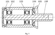
- ( CN204151507U ) are, as in Figure 5 shown, two roller bearings 103 are arranged between a shaft 106 and a bush 102, the roller bearing 103 being, for example, a ball bearing. There is an interference fit between the shaft 106 and the inner ring of the roller bearing 103, as well as between the bush 102 and the outer ring of the roller bearing 103.
- a cover 101 and a sealing ring 104 are each mounted in a groove of the bush 102.
- the connecting sleeve 105 is press-fitted onto the shaft 106.
- the cover 101 can be made of plastic and the sealing ring 104 can be made of steel.
- a yarn is wound on the outer peripheral surface of the bush 102.
- the bush 102 rotates in the circumferential direction while being carried along by the yarn. Since there is an interference fit between the bush 102 and the outer ring of the rolling bearing 103, the outer ring of the rolling bearing 103 rotates while being driven by the bush 102.
- the shaft 106 and the connecting sleeve 105 do not move between the shaft 106 and the inner ring of the rolling bearing 103 there is an interference fit, the inner ring of the rolling bearing 103 does not rotate with the bush 102.
- the present invention is based on the object of solving the above-mentioned problems of the prior art and of providing a thread guide roller with which a simple structure, simple assembly and / or disassembly, rotation of the inner ring of the rolling bearing, simple repair and / or Exchange and reusability of the component can be achieved.
- a thread guide roller comprising a cylindrical sleeve which can rotate while being carried along by an external thread; a shaft fixed with respect to the rotation of the sleeve; and a roller bearing arranged inside the bushing, the thread guide roller also comprising a connecting sleeve and a connecting part, the connecting sleeve being connected to the inner surface of the bushing so that it can follow the rotation of the bushing
- the connecting sleeve, the roller bearing and the shaft are arranged in the axial direction of the bushing, so that the connecting sleeve and the shaft are each located on the two opposite sides of the roller bearing in the axial direction, the connecting part is guided through the inner ring of the roller bearing and removably connected to the connecting sleeve and the outer ring of the roller bearing is connected to the shaft so that in the not yet connected or disconnected state of the connection of the connecting part to the connecting sleeve by means of the shaft, at least part of the connecting part and the roller bearing can be inserted into or moved
- the connecting part preferably comprises a screw and a screw nut screwed to the screw, the screw nut being arranged in the axial direction of the roller bearing on the side of the screw further away from the shaft and there being a clearance fit between the connecting sleeve and the screw.
- the thread guide roller preferably further comprises a sleeve which is mounted between the bushing and the outer ring of the roller bearing, the outer ring of the roller bearing being connected to the shaft via the sleeve.
- a concave groove is arranged on the inner surface of the sleeve and a clamping connection ring is mounted in the concave groove, which ring is arranged in the axial direction of the rolling bearing on the side of the rolling bearing further away from the shaft.
- the screw and the screw nut preferably hold the connecting sleeve and the inner ring of the roller bearing closely together in the axial direction of the roller bearing.
- the connecting sleeve preferably comprises a circular plate part and a circular ring part protruding partially in the axial direction on the radial inner side of the circular plate part, the circular ring part resting on the inner ring of the roller bearing.
- the connecting sleeve furthermore comprises a plurality of ribs extending in a radial shape and arranged on the circular plate part.
- the present invention has the advantages that the thread guide roller is easy to dismantle and maintain and, in particular after a defect in the roller bearing, the connecting part and roller bearing can simply be pulled out and replaced together, so that this is avoided that the entire thread guide roller has to be disposed of due to a laborious replacement of the roller bearing, thus saving production costs.
- the inner ring of the roller bearing of the thread guide roller rotates and the outer ring of the roller bearing does not rotate, which is advantageous for the use of a roller bearing with a single protective part. It is not necessary to construct a complicated protective part and top up with oil during maintenance, and a large number of the individual components can be reused.
- One embodiment of the present invention relates to a thread guide roller comprising a cylindrical bush 1 which can rotate while being carried along by an external yarn, a shaft 5 fixed with respect to the rotation of the bush 1 and a roller bearing arranged inside the bush 1 3, wherein the thread guide roller further comprises a connecting sleeve 2 and a connecting part, the connecting sleeve 2 is connected to the inner surface of the bush 1 so that it can follow the rotation of the bush 1.
- the connecting sleeve 2, the roller bearing 3 and the shaft 5 are arranged in the axial direction of the bush 1 so that the connecting sleeve 2 and the shaft 5 are each located on the two opposite sides of the roller bearing 3 in the axial direction, the connecting part through the inner ring of the roller bearing 3 is guided and detachably connected to the connecting sleeve 2 and the outer ring of the roller bearing 3 is connected to the shaft 5, so that in the not yet connected or disconnected state of the connection of the connecting part to the connecting sleeve 2 by means of the shaft 5, at least part of the connecting part and the Rolling bearings 3 can be inserted in the axial direction into the socket 1 or moved out of it.
- the bush 1, the connecting sleeve 2, the connecting part and the inner ring of the rolling bearing 3 can rotate together, and the outer ring of the rolling bearing 3 is fixed to the shaft 5.
- the connecting part can first be dismantled from the connecting sleeve 2 or the fastening between the connecting part and the connecting sleeve 2 can be released and then the connecting part and the roller bearing 3 can be pulled out of the socket 1 together.
- the connecting part comprises a screw 7 and a screw nut 8 screwed to the screw 7, the screw nut 8 being arranged in the axial direction of the roller bearing 3 on the side of the screw 7 further away from the shaft 5 and between the connecting sleeve 2 and the screw 7 there is a clearance fit.
- the use of the screw 7 and the screw nut 8 for the connecting part makes the present invention simple in structure and easy to implement.
- the connecting sleeve 2 rotates while being carried along by the bushing 1 and then the screw 7, the screw nut 8 and the inner ring of the roller bearing 3 rotate while being carried along by the connecting sleeve 2
- the bush 1, the connecting sleeve 2, the screw 7, the screw nut 8 and the inner ring of the roller bearing 3 rotate together.
- the thread guide roller further comprises a sleeve 4, the sleeve 4 being mounted between the bush 1 and the outer ring of the roller bearing 3 and the outer ring of the roller bearing 3 being connected to the shaft 5 via the sleeve 4.
- a structure is particularly suitable for connecting the outer ring of the rolling bearing 3 and has the effect that a connection between the shaft 5 and the outer ring of the rolling bearing 3 is formed. It is also suitable for removing the sleeve 4 from the outer ring of the roller bearing 3 after the shaft 5, the sleeve 4, the roller bearing 3 and the screw 7 have been pulled out of the socket 1, for example to replace a defective roller bearing.
- a concave groove 9 is arranged on the inner surface of the sleeve 4 and a clamping connection ring 6 is mounted in the concave groove 9, which is arranged in the axial direction of the rolling bearing 3 on the side of the rolling bearing 3 further away from the shaft 5.
- the function of the clamping connection ring 6 is to additionally hold the roller bearing 3 during regular operation of the thread guide roller and to be able to prevent its displacement in the axial direction and, when the sleeve 4 is pulled out, by the clamping connection ring 6 resting against the roller bearing 3, it also ensures that the roller bearing 3 is moved out together with the sleeve 4.
- the clamping connection ring 6 can have a structure as in FIG Figure 4 have shown, ie the clamping connection ring 6 forms approximately a C-shaped circular plate shape.
- the clamping connection ring 6 can be easily mounted in the concave groove 9 of the socket 4 and when the radial compression force acting on the clamping connection ring 6 is subsequently released, the clamping connection ring 6 becomes in the concave groove 9 clamped.
- the radial inside of the clamping connection ring 6 rests partially in the axial direction on the outer ring of the roller bearing 3 and, for example, the inside diameter of the clamping connection ring 6 can be smaller than the outside diameter of the outer ring of the roller bearing 3, thus preventing the outer ring of the roller bearing 3 from moving against the sleeve 4 is moved towards the left end in the figure and that when the shaft 5 is pulled out towards the right end in the figure, the roller bearing 3 and the screw 7 can be pulled out together.
- the radial inner end of the clamping connection ring 6 has no contact with the circular ring part 11 of the connecting sleeve 2, whereby the friction between the two can be eliminated.
- This embodiment is suitable for connecting the shaft 5 to the outer ring of the roller bearing 3 through the sleeve 4 and, after pulling out the shaft 5, the sleeve 4, the roller bearing 3 and the screw 7 from the socket 1, the sleeve 4 is easier to remove To solve the outer ring of the roller bearing 3, for example to replace a defective roller bearing.
- the sleeve 4 there is a press fit between the sleeve 4 and the outer ring of the roller bearing 3.
- the help of a tool may be required to loosen the outer ring of the roller bearing 3 from the sleeve 4, but this can still be ensured that the sleeve 4 can be pulled out in one unit with the roller bearing 3 without having to arrange a clamping connection ring 6 and thus at least one object of the present invention can also be realized.
- the screw 7 and the screw nut 8 hold the connecting sleeve 2 and the inner ring of the roller bearing 3 closely together in the axial direction of the roller bearing 3.
- the pressing of the connecting sleeve 2 and the inner ring of the roller bearing 3 against one another in the axial direction is suitable to prevent a displacement of the roller bearing 3 and the connecting sleeve 2 in the axial direction.
- the connecting sleeve 2 does not usually have to be opened or removed during the maintenance and replacement period, such an arrangement increases the stability of the structure and is better suited to completely transferring the rotational movement of the socket 1 to the connecting sleeve 2.
- the press fit between the screw 7 and the inner ring of the roller bearing 3 is better suited to allow the inner ring of the roller bearing 3 to rotate even better following the rotation of the screw 7.
- the connecting sleeve 2 as in FIG Figure 2 shown, a circular plate part 10 and a circular ring part 11 protruding partially in the axial direction on the radial inside of the circular plate part 10, the circular ring part 11 resting on the inner ring of the roller bearing 3.
- the circular ring part 11 can better guide the extension of the screw 7 in the direction of the roller bearing 3 and the fact that the circular ring part 11 rests against the inner ring of the roller bearing 3 can also prevent displacement of the roller bearing 3 in the axial direction.
- such a structure of the connecting sleeve 2 can ensure that the circular ring part 11 only comes into contact with the inner ring of the roller bearing 3 and not with other parts of the roller bearing (such as the protective part or the outer ring). In this way it can be achieved both that the connecting sleeve 2 rotates together with the inner ring of the roller bearing 3 and that the standstill of the outer ring etc. is not impaired.
- the connecting sleeve 2 furthermore comprises a plurality of radially extending ribs 12 arranged on the circular plate part 10.
- the ribs 12 can additionally increase the strength of the connecting sleeve 2 amplify and generate an air flow during rotation, which helps dissipate heat.
- the connecting sleeve 2 on the side of the connecting sleeve 2 further away from the shaft 5 (the left side in the figure) no circular ring part 11 is formed (the circular ring part 11 is formed only on one side of the circular plate part 10) and at the same time are on the side further away from the shaft 5 the connecting sleeve 2 (the left side in the figure) are also ribs 12 arranged.
- the side of the connecting sleeve 2 further away from the shaft 5 can have an identical or a different structure in any desired and suitable form to the side of the connecting sleeve 2 located closer to the shaft 5 (the right side in the figure) exhibit.
- the side of the connecting sleeve 2 further away from the shaft 5 can have no ribs 12 and at the same time form a circular ring part.
- the screw 7, the roller bearing 3, the sleeve 4 and the shaft 5 can be preassembled together, the entire component then being installed in the bore of the bush 1.
- the end part of the screw 7 is passed through the bore of the connecting sleeve 2 and then the screw 7 is tightened with the screw nut 8.
- the screw nut 8 can first be loosened, then the entire defective unit is formed from the screw 7, the roller bearing 3, the sleeve 4 and the shaft 5 pulled out and inserted a preassembled unit consisting of a screw 7, a roller bearing 3, a sleeve 4 and a shaft 5 and by tightening the nut 8, the exchange can be completed, so that the repair operations can be carried out quickly and easily.
- the sleeve 4 can still be removed from the outer ring of the roller bearing 3 solved and then only the defective roller bearing 3 replaced.
- a large part of the components of the present invention for example the bush 1, the screw 7, the screw nut 8, the sleeve 4 and the undamaged roller bearing 3) can be used again.
- the entire thread guide roller has to be disposed of because of a complex replacement of the roller bearing 3.
- the inner ring of the roller bearing can rotate while the outer ring of the roller bearing does not rotate and it is therefore particularly suitable for the use of a roller bearing with a single protective part, whereby the structure of the protective part of the rolling bearing can be simplified.
- the roller bearing of the thread guide roller of the present invention is easy to open and remove, and therefore it is not necessary to construct a complicated protective part and replenish oil for maintenance.
- the other components can also all be reused, thus saving additional costs for replacing individual parts.
- the bush 1 does not have to be exactly circular cylindrical, but it can have a bulge or a concave groove on at least one end part and / or between the two end parts.
- the two roller bearings 3 shown in the figure do not have to be in contact with one another, but rather can be separated from each other by a certain distance (for example by a spacer).
- the socket 1 can have a sealing part such as an end cover or the like at the left end.
- the connecting part of the present invention is not limited to the above-described combination of a screw 7 and a screw nut 8.
- a pin or a bolt
- a pin can be inserted into a prepared bore which is arranged on the end of the screw 7 protruding from the connecting sleeve 2 (the left end in the figure) in order to close the connecting sleeve 2 and the inner ring of the roller bearing 3 attach.
- another structure can be used for the connecting part and it only has to be given that the connecting sleeve 2 and the inner ring of the rolling bearing 3 can be fastened (e.g. fastened) to one another.
- FIG. 1 there is preferably a small gap between the right end of the screw 7 and the shaft 5. This is advantageous for the rotation of the screw 7 with respect to the shaft 5 and, moreover, the shaft 5 cannot be displaced to a greater extent in the axial direction.
- Another structure can also be arranged between the right end of the screw 7 and the shaft 5, such as a coating or a component to reduce friction (at the right end of the screw 7 and / or at the left end of the shaft 5).
- a coating for reducing friction can be arranged between the bush 1 and the sleeve 4 (on at least one of the two opposing surfaces).
- roller bearings 3 Although in Figure 1 the number of roller bearings 3 shown is two, but the number of roller bearings 3 is not limited to two and can, for example, be one, three, four or more according to actual needs.
- the connecting sleeve 2 can be made of plastic so that the connecting sleeve 2 can be removed more easily if necessary; the sleeve 4 and the shaft 5 can be made of steel in order to ensure the strength of the entire connection. Comparatively optimal exemplary embodiments of the present invention have been described above, but they do not serve to restrict the present invention and any corrections, equivalent replacements and changes etc. made within the scope of the idea and basic principles of the present invention fall within the scope of protection of the present invention Invention.
Landscapes
- Engineering & Computer Science (AREA)
- General Engineering & Computer Science (AREA)
- Mechanical Engineering (AREA)
- Textile Engineering (AREA)
- Rolling Contact Bearings (AREA)
- Rolls And Other Rotary Bodies (AREA)
- Spinning Methods And Devices For Manufacturing Artificial Fibers (AREA)
- Mounting Of Bearings Or Others (AREA)
Description
Die vorliegende Erfindung betrifft das technische Gebiet der Textilherstellungsmaschinen, und sie ist insbesondere vorteilhaft an einer Fadenführungsrolle realisierbar.The present invention relates to the technical field of textile manufacturing machines, and it can particularly advantageously be implemented on a thread guide roller.
In für die Textilherstellung verwendeten Fadenführungsrollen des Stands der Technik: (
Auf die Außenumfangsfläche der Buchse 102 ist ein Garn gewickelt. In der Anwendung rotiert die Buchse 102 unter der Mitnahme durch das Garn in Umfangsrichtung. Da zwischen der Buchse 102 und dem Außenring des Wälzlagers 103 eine Presspassung besteht, rotiert der Außenring des Wälzlagers 103 unter der Mitnahme durch die Buchse 102. Die Welle 106 und die Verbindungshülse 105 bewegen sich nicht und da zwischen der Welle 106 und dem Innenring des Wälzlagers 103 eine Presspassung besteht, rotiert der Innenring des Wälzlagers 103 nicht mit der Buchse 102.A yarn is wound on the outer peripheral surface of the
Nachteilig bei dem oben beschriebenen Stand der Technik ist es, dass aufgrund dessen, dass der Außenring des Wälzlagers rotiert, die Konstruktion des Schutzteils des Wälzlagers komplizierter im Hinblick auf die Zuverlässigkeit wird und/ oder sich die Lebensdauer des Schutzteils verringert und dass zwei komplizierte und teure Dichtungsteile konstruiert werden müssen. Darüber hinaus lässt sich das Wälzlager nach einer Beschädigung nicht einfach tauschen. Um die Lebensdauer des Wälzlagers zu verbessern, muss im Allgemeinen nach einem Jahr das Basisöl des Schmierfetts aufgefüllt werden, was für den Endnutzer zusätzliche Kosten bedeutet. Außerdem ist im Falle eines Defekts des Wälzlagers im Allgemeinen das gesamte Bauteil unbrauchbar und die Buchse kann nicht wiederverwendet werden. Dies bedeutet Verschwendung und ist von Nachteil für die Umwelt.It is disadvantageous in the prior art described above that, because the outer ring of the rolling bearing rotates, the construction of the protective part of the rolling bearing becomes more complicated in terms of reliability and / or the life of the protective part is reduced and that two complicated and expensive Sealing parts need to be designed. In addition, the rolling bearing cannot simply be replaced after damage. In order to improve the life of the rolling bearing, the base oil of the grease must generally be replenished after one year, which means additional costs for the end user. In addition, in the event of a defect in the rolling bearing, the entire component is generally unusable and the bushing cannot be reused. This is wasteful and is detrimental to the environment.
Der vorliegenden Erfindung liegt die Aufgabe zugrunde, die oben aufgeführten Probleme des Standes der Technik zu lösen und eine Fadenführungsrolle bereitzustellen, mit der ein einfacher Aufbau, eine einfache Montage und/oder Demontage, eine Rotation des Innenrings des Wälzlagers, eine einfache Reparatur und/oder Austausch und eine Wiederverwendbarkeit des Bauteils erreicht werden kann.The present invention is based on the object of solving the above-mentioned problems of the prior art and of providing a thread guide roller with which a simple structure, simple assembly and / or disassembly, rotation of the inner ring of the rolling bearing, simple repair and / or Exchange and reusability of the component can be achieved.
Die obenstehende Aufgabe der vorliegenden Erfindung kann durch die folgende technische Lösung realisiert werden, ist aber nicht auf diese beschränkt.The above object of the present invention can be realized by the following technical solution, but is not limited to this.
Eine Fadenführungsrolle, umfassend eine zylinderförmige Buchse, die unter der Mitnahme durch ein externes Garn rotieren kann; eine in Bezug auf die Rotation der Buchse feststehende Welle; sowie ein im Innern der Buchse angeordnetes Wälzlager, wobei die Fadenführungsrolle außerdem eine Verbindungshülse und ein Verbindungsteil umfasst, die Verbindungshülse so mit der Innenoberfläche der Buchse verbunden ist, dass sie der Rotation der Buchse folgen kann, die Verbindungshülse, das Wälzlager und die Welle in Axialrichtung der Buchse angeordnet sind, so dass sich die Verbindungshülse und die Welle jeweils an den beiden entgegengesetzten Seiten des Wälzlagers in Axialrichtung befinden, das Verbindungsteil durch den Innenring des Wälzlagers geführt und abnehmbar mit der Verbindungshülse verbunden ist und der Außenring des Wälzlagers mit der Welle verbunden ist, sodass im noch nicht verbundenen oder gelösten Zustand der Verbindung des Verbindungsteils zur Verbindungshülse mittels der Welle mindestens ein Teil des Verbindungsteils und das Wälzlager in Axialrichtung in die Buchse hineingesteckt oder aus dieser herausbewegt werden können.A thread guide roller comprising a cylindrical sleeve which can rotate while being carried along by an external thread; a shaft fixed with respect to the rotation of the sleeve; and a roller bearing arranged inside the bushing, the thread guide roller also comprising a connecting sleeve and a connecting part, the connecting sleeve being connected to the inner surface of the bushing so that it can follow the rotation of the bushing The connecting sleeve, the roller bearing and the shaft are arranged in the axial direction of the bushing, so that the connecting sleeve and the shaft are each located on the two opposite sides of the roller bearing in the axial direction, the connecting part is guided through the inner ring of the roller bearing and removably connected to the connecting sleeve and the outer ring of the roller bearing is connected to the shaft so that in the not yet connected or disconnected state of the connection of the connecting part to the connecting sleeve by means of the shaft, at least part of the connecting part and the roller bearing can be inserted into or moved out of the bushing in the axial direction.
Vorzugsweise umfasst das Verbindungsteil eine Schraube und eine mit der Schraube verschraubte Schraubenmutter, wobei die Schraubenmutter in Axialrichtung des Wälzlagers an der von der Welle entfernteren Seite der Schraube angeordnet ist und zwischen der Verbindungshülse und der Schraube eine Spielpassung besteht.The connecting part preferably comprises a screw and a screw nut screwed to the screw, the screw nut being arranged in the axial direction of the roller bearing on the side of the screw further away from the shaft and there being a clearance fit between the connecting sleeve and the screw.
Vorzugsweise umfasst die Fadenführungsrolle weiterhin eine Muffe, die zwischen der Buchse und dem Außenring des Wälzlagers montiert ist, wobei der Außenring des Wälzlagers über die Muffe mit der Welle verbunden ist.The thread guide roller preferably further comprises a sleeve which is mounted between the bushing and the outer ring of the roller bearing, the outer ring of the roller bearing being connected to the shaft via the sleeve.
Vorzugsweise ist an der Innenoberfläche der Muffe eine Konkavnut angeordnet und in der Konkavnut ist ein Klemmverbindungsring montiert, der in Axialrichtung des Wälzlagers an der von der Welle entfernteren Seite des Wälzlagers angeordnet ist.Preferably, a concave groove is arranged on the inner surface of the sleeve and a clamping connection ring is mounted in the concave groove, which ring is arranged in the axial direction of the rolling bearing on the side of the rolling bearing further away from the shaft.
Vorzugsweise besteht zwischen der Muffe und dem Außenring des Wälzlagers eine Spielpassung oder eine Presspassung.There is preferably a clearance fit or an interference fit between the sleeve and the outer ring of the roller bearing.
Vorzugsweise halten die Schraube und die Schraubenmutter in Axialrichtung des Wälzlagers die Verbindungshülse und den Innenring des Wälzlagers eng zusammen.The screw and the screw nut preferably hold the connecting sleeve and the inner ring of the roller bearing closely together in the axial direction of the roller bearing.
Vorzugsweise besteht zwischen der Buchse und der Verbindungshülse eine Presspassung und zwischen dem Innenring des Wälzlagers und der Schraube ebenfalls eine Presspassung.There is preferably a press fit between the bushing and the connecting sleeve, and there is also a press fit between the inner ring of the roller bearing and the screw.
Vorzugsweise umfasst die Verbindungshülse einen Kreisplattenteil und einen an der radialen Innenseite des Kreisplattenteils teilweise in Axialrichtung hervorstehenden Kreisringteil, wobei der Kreisringteil am Innenring des Wälzlagers anliegt.The connecting sleeve preferably comprises a circular plate part and a circular ring part protruding partially in the axial direction on the radial inner side of the circular plate part, the circular ring part resting on the inner ring of the roller bearing.
Vorzugsweise umfasst die Verbindungshülse weiterhin mehrere am Kreisplattenteil angeordnete strahlenförmig erstreckte Rippen.Preferably, the connecting sleeve furthermore comprises a plurality of ribs extending in a radial shape and arranged on the circular plate part.
Im Vergleich zum Stand der Technik und den entsprechenden Produkten weist die vorliegende Erfindung die Vorteile auf, dass die Fadenführungsrolle einfach zu demontieren und instand zu halten ist und insbesondere nach einem Defekt des Wälzlagers Verbindungsteil und Wälzlager einfach gemeinsam herausgezogen und getauscht werden können, sodass vermieden wird, dass aufgrund eines aufwändigen Tauschs des Wälzlagers die gesamte Fadenführungsrolle entsorgt werden muss und somit Produktionskosten gespart werden. Bei einer Fadenführungsrolle gemäß der vorliegenden Erfindung rotiert der Innenring des Wälzlagers der Fadenführungsrolle und der Außenring des Wälzlagers rotiert nicht, was vorteilhaft für die Verwendung eines Wälzlagers mit einem einzelnen Schutzteil ist. Die Konstruktion eines komplizierten Schutzteils und das Nachfüllen von Öl bei der Instandhaltung sind nicht notwendig und ein großer Teil der Einzelkomponenten kann wiederverwendet werden.Compared to the prior art and the corresponding products, the present invention has the advantages that the thread guide roller is easy to dismantle and maintain and, in particular after a defect in the roller bearing, the connecting part and roller bearing can simply be pulled out and replaced together, so that this is avoided that the entire thread guide roller has to be disposed of due to a laborious replacement of the roller bearing, thus saving production costs. In a thread guide roller according to the present invention, the inner ring of the roller bearing of the thread guide roller rotates and the outer ring of the roller bearing does not rotate, which is advantageous for the use of a roller bearing with a single protective part. It is not necessary to construct a complicated protective part and top up with oil during maintenance, and a large number of the individual components can be reused.
Die Erfindung wird nachfolgend anhand eines bevorzugten Ausführungsbeispiels unter Bezugnahme auf die beigefügten Zeichnungen näher erläutert. Dabei zeigen:
- Figur 1
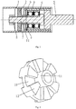
- eine Schnittdarstellung einer erfindungsgemäß ausgebildeten Fadenführungsrolle;
Figur 2- eine schematische Darstellung der näher zur Welle befindlichen Seite der Verbindungshülse einer erfindungsgemäß ausgebildeten Fadenführungsrolle;
- Figur 3
- eine schematische Darstellung der entfernter zur Welle befindlichen Seite der Verbindungshülse einer erfindungsgemäß ausgebildeten Fadenführungsrolle;
- Figur 4
- eine schematische Darstellung des Klemmverbindungsrings einer erfindungsgemäß ausgebildeten Fadenführungsrolle;
- Figur 5
- eine Schnittdarstellung einer Fadenführungsrolle des Stands der Technik.
- Figure 1
- a sectional view of a thread guide roller designed according to the invention;
- Figure 2
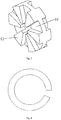
- a schematic representation of the closer to the shaft side of the connecting sleeve of a thread guide roller designed according to the invention;
- Figure 3
- a schematic representation of the remote side of the connecting sleeve from the shaft of a thread guide roller designed according to the invention;
- Figure 4
- a schematic representation of the clamping connection ring of a thread guide roller designed according to the invention;
- Figure 5
- a sectional view of a thread guide roller of the prior art.
Wie in
Auf Grundlage des oben beschriebenen Aufbaus können die Buchse 1, die Verbindungshülse 2, das Verbindungsteil und der Innenring des Wälzlagers 3 gemeinsam rotieren und der Außenring des Wälzlagers 3 ist an der Welle 5 befestigt. Somit kann, wenn beispielsweise ein defektes Wälzlager 3 getauscht werden muss, zunächst das Verbindungsteil von der Verbindungshülse 2 demontiert beziehungsweise die Befestigung zwischen dem Verbindungsteil und der Verbindungshülse 2 gelöst werden und anschließend das Verbindungsteil und das Wälzlager 3 gemeinsam aus der Buchse 1 herausgezogen werden.Based on the structure described above, the bush 1, the connecting
Gemäß einer bevorzugten Ausführungsform umfasst das Verbindungsteil eine Schraube 7 und eine mit der Schraube 7 verschraubte Schraubenmutter 8, wobei die Schraubenmutter 8 in Axialrichtung des Wälzlagers 3 an der entfernter zur Welle 5 befindlichen Seite der Schraube 7 angeordnet ist und zwischen der Verbindungshülse 2 und der Schraube 7 eine Spielpassung besteht. Die Verwendung der Schraube 7 und der Schraubenmutter 8 für das Verbindungsteil macht die vorliegende Erfindung einfach im Aufbau und leicht zu realisieren. Wenn in der Anwendung die Bewegung des externen Garns die Rotation der Buchse 1 antreibt, rotiert die Verbindungshülse 2 unter Mitnahme durch die Buchse 1 und anschließend rotieren die Schraube 7, die Schraubenmutter 8 und der Innenring des Wälzlagers 3 unter Mitnahme durch die Verbindungshülse 2. Mit anderen Worten rotieren die Buchse 1, die Verbindungshülse 2, die Schraube 7, die Schraubenmutter 8 und der Innenring des Wälzlagers 3 gemeinsam. Da der Außenring des Wälzlagers 3 mit der extern befestigten Welle 5 verbunden ist, rotiert der Außenring des Wälzlagers 3 nicht mit der Buchse 1, der Verbindungshülse 2, der Schraube 7, der Schraubenmutter 8 und dem Innenring des Wälzlagers 3. Damit müssen beispielsweise bei einer Instandhaltung nur der in
Gemäß einer bevorzugten Ausführungsform ist an der Innenoberfläche der Muffe 4 eine Konkavnut 9 angeordnet und in der Konkavnut 9 ist ein Klemmverbindungsring 6 montiert, der in Axialrichtung des Wälzlagers 3 an der von der Welle 5 entfernteren Seite des Wälzlagers 3 angeordnet ist. Die Funktion des Klemmverbindungsrings 6 ist es, im regulären Betrieb der Fadenführungsrolle das Wälzlager 3 zusätzlich zu halten und dessen Verschiebung in Axialrichtung verhindern zu können und beim Herausziehen der Muffe 4 durch das Anliegen des Klemmverbindungsrings 6 am Wälzlager 3 zusätzlich zu gewährleisten, dass das Wälzlager 3 gemeinsam mit der Muffe 4 herausbewegt wird. In einem Beispiel kann der Klemmverbindungsring 6 einen Aufbau wie in
Gemäß einer bevorzugten Ausführungsform besteht zwischen der Muffe 4 und dem Außenring des Wälzlagers 3 eine Spielpassung. Diese Ausführungsform ist geeignet, um durch die Muffe 4 die Welle 5 mit dem Außenring des Wälzlagers 3 zu verbinden und nach dem gemeinsamen Herausziehen der Welle 5, der Muffe 4, des Wälzlagers 3 und der Schraube 7 aus der Buchse 1 die Muffe 4 einfacher vom Außenring des Wälzlagers 3 zu lösen, um beispielsweise ein defektes Wälzlager zu tauschen.According to a preferred embodiment, there is a clearance fit between the sleeve 4 and the outer ring of the roller bearing 3. This embodiment is suitable for connecting the shaft 5 to the outer ring of the roller bearing 3 through the sleeve 4 and, after pulling out the shaft 5, the sleeve 4, the roller bearing 3 and the screw 7 from the socket 1, the sleeve 4 is easier to remove To solve the outer ring of the roller bearing 3, for example to replace a defective roller bearing.
Gemäß einer alternativen Ausführungsform besteht zwischen der Muffe 4 und dem Außenring des Wälzlagers 3 eine Presspassung. Obwohl bei dieser Ausführungsform nach dem gemeinsamen Herausziehen der Welle 5, der Muffe 4, des Wälzlagers 3 und der Schraube 7 aus der Buchse 1 für das Lösen des Außenrings des Wälzlagers 3 von der Muffe 4 möglicherweise die Hilfe eines Werkzeugs benötigt wird, kann dennoch sichergestellt werden, dass die Muffe 4 in einer Einheit mit dem Wälzlager 3 herausgezogen werden kann, ohne dass ein Klemmverbindungsring 6 angeordnet werden muss und somit genauso mindestens ein Ziel der vorliegenden Erfindung realisiert werden kann.According to an alternative embodiment, there is a press fit between the sleeve 4 and the outer ring of the roller bearing 3. Although, in this embodiment, after the shaft 5, the sleeve 4, the roller bearing 3 and the screw 7 have been pulled out of the bush 1 together, the help of a tool may be required to loosen the outer ring of the roller bearing 3 from the sleeve 4, but this can still be ensured that the sleeve 4 can be pulled out in one unit with the roller bearing 3 without having to arrange a clamping connection ring 6 and thus at least one object of the present invention can also be realized.
Gemäß einer bevorzugten Ausführungsform besteht zwischen der Muffe 4 und der Welle 5 eine Schraubverbindung. Die Vorteile dabei sind die Festigkeit der Verbindung zwischen der Muffe 4 und der Welle 5, der einfache Aufbau und die problemlose Umsetzung.According to a preferred embodiment, there is a screw connection between the sleeve 4 and the shaft 5. The advantages here are the strength of the connection between the sleeve 4 and the shaft 5, the simple structure and the problem-free implementation.
Gemäß einer bevorzugten Ausführungsform halten die Schraube 7 und die Schraubenmutter 8 in Axialrichtung des Wälzlagers 3 die Verbindungshülse 2 und den Innenring des Wälzlagers 3 eng zusammen. Das Aneinanderdrücken der Verbindungshülse 2 und des Innenrings des Wälzlagers 3 in Axialrichtung ist geeignet, um eine Verschiebung des Wälzlagers 3 und der Verbindungshülse 2 in Axialrichtung zu verhindern.According to a preferred embodiment, the screw 7 and the screw nut 8 hold the connecting
Gemäß einer bevorzugten Ausführungsform besteht zwischen der Buchse 1 und der Verbindungshülse 2 eine Presspassung und zwischen dem Innenring des Wälzlagers 3 und der Schraube 7 ebenfalls eine Presspassung. Da im Instandhaltungs- und Austauschzeitraum in der Regel kein Öffnen und keine Entnahme der Verbindungshülse 2 erforderlich ist, erhöht eine solche Anordnung die Stabilität des Aufbaus und ist besser geeignet, die Rotationsbewegung der Buchse 1 vollständig an die Verbindungshülse 2 weiterzuleiten. Darüber hinaus ist die Presspassung zwischen der Schraube 7 und dem Innenring des Wälzlagers 3 besser geeignet, um den Innenring des Wälzlagers 3 noch besser der Rotation der Schraube 7 folgend rotieren zu lassen.According to a preferred embodiment, there is a press fit between the bush 1 and the connecting
Gemäß einer bevorzugten Ausführungsform umfasst die Verbindungshülse 2, wie in
Gemäß einer bevorzugten Ausführungsform umfasst die Verbindungshülse 2 weiterhin mehrere am Kreisplattenteil 10 angeordnete strahlenförmig erstreckte Rippen 12. Die Rippen 12 können die Festigkeit der Verbindungshülse 2 zusätzlich verstärken und während der Rotation einen Luftstrom erzeugen, der die Wärmeableitung unterstützt.According to a preferred embodiment, the connecting
Darüber hinaus ist in einem Beispiel, wie in
In der tatsächlichen Anwendung können beispielsweise die Schraube 7, das Wälzlager 3, die Muffe 4 und die Welle 5 gemeinsam vormontiert sein, wobei anschließend das gesamte Bauteil in der Bohrung der Buchse 1 montiert wird. Der Endteil der Schraube 7 wird durch die Bohrung der Verbindungshülse 2 geführt und anschließend wird die Schraube 7 mit der Schraubenmutter 8 festgezogen.In the actual application, for example, the screw 7, the roller bearing 3, the sleeve 4 and the shaft 5 can be preassembled together, the entire component then being installed in the bore of the bush 1. The end part of the screw 7 is passed through the bore of the connecting
Im Vergleich zum Stand der Technik kann bei einem Defekt des Wälzlagers 3 in einer Fadenführungsrolle gemäß der vorliegenden Erfindung zunächst die Schraubenmutter 8 gelöst werden, anschließend wird die gesamte defekte aus der Schraube 7, dem Wälzlager 3, der Muffe 4 und der Welle 5 gebildete Einheit herausgezogen und eine vormontierte Einheit aus einer Schraube 7, einem Wälzlager 3, einer Muffe 4 und einer Welle 5 eingesetzt und mit dem Festziehen der Schraubenmutter 8 kann der Tausch abgeschlossen werden, womit die Reparaturhandlungen einfach und schnell auszuführen sind. Darüber hinaus kann bei der getauschten Schraube 7, der Schraubenmutter 8, dem Wälzlager 3, der Muffe 4 und der Welle 5 weiterhin die Muffe 4 vom Außenring des Wälzlagers 3 gelöst und anschließend nur das defekte Wälzlager 3 getauscht werden. So kann ein großer Teil der Komponenten der vorliegenden Erfindung (z.B. die Buchse 1, die Schraube 7, die Schraubenmutter 8, die Muffe 4 und das unbeschädigte Wälzlager 3) erneut genutzt werden. Auf Grundlage des oben aufgeführten Aufbaus wird vermieden, dass wegen eines aufwändigen Tauschs des Wälzlagers 3 die gesamte Fadenführungsrolle entsorgt werden muss.Compared to the prior art, in the event of a defect in the roller bearing 3 in a thread guide roller according to the present invention, the screw nut 8 can first be loosened, then the entire defective unit is formed from the screw 7, the roller bearing 3, the sleeve 4 and the shaft 5 pulled out and inserted a preassembled unit consisting of a screw 7, a roller bearing 3, a sleeve 4 and a shaft 5 and by tightening the nut 8, the exchange can be completed, so that the repair operations can be carried out quickly and easily. In addition, when the screw 7, the screw nut 8, the roller bearing 3, the sleeve 4 and the shaft 5 have been replaced, the sleeve 4 can still be removed from the outer ring of the roller bearing 3 solved and then only the defective roller bearing 3 replaced. A large part of the components of the present invention (for example the bush 1, the screw 7, the screw nut 8, the sleeve 4 and the undamaged roller bearing 3) can be used again. On the basis of the structure listed above, it is avoided that the entire thread guide roller has to be disposed of because of a complex replacement of the roller bearing 3.
Darüber hinaus besteht im Vergleich zum Stand der Technik der Vorteil, dass bei einer Fadenführungsrolle der vorliegenden Erfindung der Innenring des Wälzlagers rotieren kann, während der Außenring des Wälzlagers nicht rotiert und sie daher insbesondere für die Verwendung eines Wälzlagers mit einem einzelnen Schutzteil geeignet ist, womit der Aufbau des Schutzteils des Wälzlagers vereinfacht werden kann. Außerdem ist das Wälzlager der Fadenführungsrolle der vorliegenden Erfindung einfach zu öffnen und zu entnehmen, weshalb die Konstruktion eines komplizierten Schutzteils und das Nachfüllen von Öl bei der Instandhaltung nicht notwendig sind. Darüber hinaus können die anderen Bauteile ebenfalls alle wiederverwendet werden und so weitere Kosten für den Austausch von Einzelteilen eingespart werden.In addition, compared to the prior art, there is the advantage that in a thread guide roller of the present invention, the inner ring of the roller bearing can rotate while the outer ring of the roller bearing does not rotate and it is therefore particularly suitable for the use of a roller bearing with a single protective part, whereby the structure of the protective part of the rolling bearing can be simplified. In addition, the roller bearing of the thread guide roller of the present invention is easy to open and remove, and therefore it is not necessary to construct a complicated protective part and replenish oil for maintenance. In addition, the other components can also all be reused, thus saving additional costs for replacing individual parts.
Die vorliegende Erfindung ist nicht beschränkt auf den oben beschriebenen konkreten/bevorzugten Aufbau und ein Fachmann des technischen Gebiets kann selbstverständlich unter der oben beschriebenen Anleitung alle Arten von Veränderungen und Ersetzungen vornehmen, wobei die Veränderungen und Ersetzungen die folgenden Aspekte umfassen, aber nicht auf diese beschränkt sind.The present invention is not limited to the specific / preferred construction described above, and a person skilled in the technical field can of course make all kinds of changes and substitutions under the guidance described above, the changes and substitutions including but not limited to the following aspects are.
Die Form und Position eines jeden Bauteils ist nicht auf die oben beschriebenen Umstände beschränkt und es muss lediglich gegeben sein, dass die Funktionen der vorliegenden Erfindung realisiert werden können.The shape and position of each component are not limited to the circumstances described above, and it is only necessary that the functions of the present invention can be realized.
Beispielsweise muss die Buchse 1 nicht genau kreiszylinderförmig sein, sondern sie kann an mindestens einem Endteil und/oder zwischen beiden Endteilen eine Ausbuchtung oder eine Konkavnut aufweisen. Die in der Figur dargestellten beiden Wälzlager 3 müssen auch nicht aneinander anliegen, sondern können (beispielsweise durch ein Distanzstück) durch einen bestimmten Abstand voneinander getrennt sein.For example, the bush 1 does not have to be exactly circular cylindrical, but it can have a bulge or a concave groove on at least one end part and / or between the two end parts. The two roller bearings 3 shown in the figure do not have to be in contact with one another, but rather can be separated from each other by a certain distance (for example by a spacer).
Obwohl in der Figur nicht dargestellt, kann die Buchse 1 am linken Ende ein Dichtungsteil wie beispielsweise einen Enddeckel o. ä. aufweisen.Although not shown in the figure, the socket 1 can have a sealing part such as an end cover or the like at the left end.
Das Verbindungsteil der vorliegenden Erfindung ist nicht auf die oben beschriebene Kombination aus einer Schraube 7 und einer Schraubenmutter 8 beschränkt. Beispielsweise kann ein Stift (oder ein Bolzen) in eine vorbereitete Bohrung gesteckt sein, die an dem aus der Verbindungshülse 2 hervorgestreckten Ende der Schraube 7 (in der Figur das linke Ende) angeordnet ist, um die Verbindungshülse 2 und den Innenring des Wälzlagers 3 zu befestigen. Natürlich kann für das Verbindungsteil noch ein anderer Aufbau verwendet werden und es muss lediglich gegeben sein, dass die Verbindungshülse 2 und der Innenring des Wälzlagers 3 aneinander befestigt (z.B. befestigt) werden können.The connecting part of the present invention is not limited to the above-described combination of a screw 7 and a screw nut 8. For example, a pin (or a bolt) can be inserted into a prepared bore which is arranged on the end of the screw 7 protruding from the connecting sleeve 2 (the left end in the figure) in order to close the connecting
Wie in
Obwohl in
Die Verbindungshülse 2 kann aus Kunststoff gefertigt sein, damit die Verbindungshülse 2 bei Bedarf einfacher entnommen werden kann; die Muffe 4 und die Welle 5 können aus Stahl gefertigt sein, um die Festigkeit der gesamten Verbindung zu gewährleisten. Obenstehend wurden vergleichsweise optimale Ausführungsbeispiele der vorliegenden Erfindung beschrieben, die aber nicht dazu dienen, die vorliegende Erfindung einzuschränken und jegliche Korrekturen, gleichwertige Ersetzungen und Änderungen etc. die im Rahmen der Idee und der Grundprinzipien der vorliegenden Erfindung vorgenommen werden, fallen in den Schutzumfang der vorliegenden Erfindung.The connecting
- 11
- BuchseRifle
- 22
- VerbindungshülseConnecting sleeve
- 33
- Wälzlagerroller bearing
- 44th
- Muffesleeve
- 55
- Wellewave
- 66th
- KlemmverbindungsringClamp connection ring
- 77th
- Schraubescrew
- 88th
- SchraubenmutterScrew nut
- 99
- KonkavnutConcave groove
- 1010
- KreisplattenteilCircular plate part
- 1111
- KreisringteilAnnulus part
- 1212
- Ripperib
- 101101
- Deckelcover
- 102102
- BuchseRifle
- 103103
- Wälzlagerroller bearing
- 104104
- DichtungsringSealing ring
- 105105
- VerbindungshülseConnecting sleeve
- 106106
- Wellewave
Claims (10)
- A godet roller, comprising a cylindrical bushing (1) capable of rotating under the driving of an external yarn; a shaft (5) fixed relative to the rotation of the bushing (1) and a roller bearing (3) arranged inside the bushing (1), characterised in that the godet roller further comprises a connecting sleeve (2) and a connecting component, the connecting sleeve (2) is connected to the inner surface of the bushing (1) so as to be able to rotate along with the bushing (1), the connecting sleeve (2), the roller bearing (3) and the shaft (5) are arranged along the axial direction of the bushing (1) so that the connecting sleeve (2) and the shaft (5) are respectively located on the two opposite sides of the roller bearing (3) in the axial direction, the connecting component is guided through the inner ring of the roller bearing (3) and is detachably connected to the connecting sleeve (2) and the outer ring of the roller bearing (3) is connected to the shaft (5) so that, in a case in which the connecting component is not yet connected to the connecting sleeve (2) or the connection therebetween is cancelled, at least one part of the connecting component and the roller bearing (3) can be inserted into or moved out of the bushing (1) along the axial direction by means of the shaft (5).
- The godet roller according to claim 1, characterised in that the connecting component comprises a screw (7) and a screw nut (8) screwed to the screw (7), wherein the screw nut (8) is arranged in the axial direction of the roller bearing (3) on the side of the screw (7) that is further away from the shaft (5) and there is a clearance fit between the connecting sleeve (2) and the screw (7).
- The godet roller according to claim 1, characterised in that the godet roller further comprises a sleeve (4), wherein the sleeve (4) is mounted between the bushing (1) and the outer ring of the roller bearing (3) and the outer ring of the roller bearing (3) is connected to the shaft (5) via the sleeve (4).
- The godet roller according to claim 3, characterised in that a concave groove (9) is arranged on the inner surface of the sleeve (4) and a clamping connection ring (6) is mounted in the concave groove (9), which clamping connection ring is arranged in the axial direction of the roller bearing (3) on the side of the roller bearing (3) further away from the shaft (5).
- The godet roller according to claim 4, characterised in that a clearance fit exists between the sleeve (4) and the outer ring of the roller bearing (3).
- The godet roller according to claim 4, characterised in that a press fit exists between the sleeve (4) and the outer ring of the roller bearing (3).
- The godet roller according to any one of claims 2 to 6, characterised in that the screw (7) and the screw nut (8) hold the connecting sleeve (2) and the inner ring of the roller bearing (3) close together along the axial direction of the roller bearing (3).
- The godet roller according to claim 7, characterised in that a press fit exists between the bushing (1) and the connecting sleeve (2) and in that a press fit exists between the inner ring of the roller bearing (3) and the screw (7).
- The godet roller according to any one of claims 1 to 6, characterised in that the connecting sleeve (2) comprises a circular plate component (10) and a circular ring component (11) partially protruding along the axial direction on the radial inner side of the circular plate component (10), wherein the circular ring component (11) abuts the inner ring of the roller bearing (3).
- The godet roller according to claim 9, characterised in that the connecting sleeve (2) further comprises a plurality of ribs (12) extending in the form of rays and arranged on the circular plate component (10).
Applications Claiming Priority (2)
| Application Number | Priority Date | Filing Date | Title |
|---|---|---|---|
| CN201510212717.7A CN106192099B (en) | 2015-04-29 | 2015-04-29 | godet roll |
| PCT/CN2016/079942 WO2016173456A1 (en) | 2015-04-29 | 2016-04-21 | Godet roller |
Publications (3)
| Publication Number | Publication Date |
|---|---|
| EP3290552A1 EP3290552A1 (en) | 2018-03-07 |
| EP3290552A4 EP3290552A4 (en) | 2018-12-19 |
| EP3290552B1 true EP3290552B1 (en) | 2021-01-06 |
Family
ID=57198150
Family Applications (1)
| Application Number | Title | Priority Date | Filing Date |
|---|---|---|---|
| EP16785887.7A Active EP3290552B1 (en) | 2015-04-29 | 2016-04-21 | Godet roller |
Country Status (3)
| Country | Link |
|---|---|
| EP (1) | EP3290552B1 (en) |
| CN (1) | CN106192099B (en) |
| WO (1) | WO2016173456A1 (en) |
Families Citing this family (3)
| Publication number | Priority date | Publication date | Assignee | Title |
|---|---|---|---|---|
| CN111926425B (en) * | 2020-08-26 | 2025-03-28 | 何丰 | A guide wheel assembly for textile machinery |
| CN114381855B (en) * | 2021-12-22 | 2024-04-19 | 常德纺织机械有限公司 | Axial positioning structure for swing shaft of warp knitting machine |
| DE102022001053A1 (en) | 2022-03-25 | 2023-09-28 | Oerlikon Textile Gmbh & Co. Kg | Galette for guiding and conveying a thread |
Citations (1)
| Publication number | Priority date | Publication date | Assignee | Title |
|---|---|---|---|---|
| CN204151507U (en) * | 2014-09-20 | 2015-02-11 | 徐兆成 | One exempts from the free of contamination combined type upper roller bearing of greasing |
Family Cites Families (12)
| Publication number | Priority date | Publication date | Assignee | Title |
|---|---|---|---|---|
| DE1690405U (en) * | 1954-10-14 | 1954-12-30 | Duerkoppwerke Ag | PRESSURE ROLLERS FOR SPINNING MACHINES. |
| FR2122889A5 (en) * | 1971-01-21 | 1972-09-01 | Kugelfischer G Schaefer & Co | Godet roll - for hot draw twisting of yarns, has shell spaced from bearing by insulator |
| DE7905441U1 (en) * | 1979-02-27 | 1979-07-05 | Akzo Gmbh, 5600 Wuppertal | Overflow roller that can be stored aerodynamically |
| DE19947418B4 (en) * | 1999-10-01 | 2014-05-15 | Rieter Ingolstadt Gmbh | Bearing element for the storage of top rollers of drafting systems |
| DE10111598A1 (en) * | 2001-03-10 | 2002-09-12 | Barmag Barmer Maschf | The godet roller, for use with melt spun filaments, has a spring to apply a static pressure to the roller bearings and an actuator, operated by compressed air, to adjust the spring pressure according to the working conditions |
| DE102004061451A1 (en) * | 2004-12-17 | 2006-06-29 | Maschinenfabrik Rieter Ag | Roll for textile machines has hub and shaft connected by separate clamping members pressed between shaft and hub or profiled surfaces of hub and shaft being pressed against each other |
| DE102005046392A1 (en) * | 2005-09-28 | 2007-03-29 | Hans Stahlecker | Bearing arrangement for fixed rollers comprises a sleeve-like centerpiece with two bearings carrying the roller shaft, where the outer rings of the bearings are mounted on the outer periphery of the centerpiece |
| CN101326316B (en) * | 2005-12-10 | 2010-11-03 | 欧瑞康纺织有限及两合公司 | Idler roller |
| DE102008020018B3 (en) * | 2008-04-22 | 2009-10-01 | GÖRGENS, Detlef | Pinch roller for texturing machine, has ball bearing comprising inner race accommodated by outer bearing part, where bearing part and grooved ball bearing are relubricated through lubrication bore |
| DE102008029482A1 (en) * | 2008-06-20 | 2009-12-24 | Schaeffler Kg | Bearing, particularly bearing of thread guiding roller of textile machine, for shaft at axle, has magnetic radial bearing and another magnetic radial bearing at axial distance from former magnetic radial bearing |
| DE102010009467A1 (en) * | 2010-01-15 | 2011-07-21 | Oerlikon Textile Components GmbH, 70736 | Pressure roller for thread supply mechanism of textile machine, has roller bearing comprising inner ring that is provided with supporting groove for accommodating supporting ring, where supporting ring is clamped between groove and axle |
| EP2984219A1 (en) * | 2013-04-09 | 2016-02-17 | Oerlikon Textile GmbH & Co. KG | Godet roll |
-
2015
- 2015-04-29 CN CN201510212717.7A patent/CN106192099B/en active Active
-
2016
- 2016-04-21 EP EP16785887.7A patent/EP3290552B1/en active Active
- 2016-04-21 WO PCT/CN2016/079942 patent/WO2016173456A1/en not_active Ceased
Patent Citations (1)
| Publication number | Priority date | Publication date | Assignee | Title |
|---|---|---|---|---|
| CN204151507U (en) * | 2014-09-20 | 2015-02-11 | 徐兆成 | One exempts from the free of contamination combined type upper roller bearing of greasing |
Also Published As
| Publication number | Publication date |
|---|---|
| CN106192099B (en) | 2020-10-23 |
| EP3290552A4 (en) | 2018-12-19 |
| EP3290552A1 (en) | 2018-03-07 |
| WO2016173456A1 (en) | 2016-11-03 |
| CN106192099A (en) | 2016-12-07 |
Similar Documents
| Publication | Publication Date | Title |
|---|---|---|
| EP3942189B1 (en) | Plain bearing arrangement | |
| DE102013223329A1 (en) | Gas dynamic air bearing | |
| EP2703693B1 (en) | Planet carrier | |
| DE102012203178B4 (en) | Power transmission device of a rotary wing aircraft | |
| EP3290552B1 (en) | Godet roller | |
| DE102017217562A1 (en) | Bearing locking device and method for its operation | |
| EP3333439A1 (en) | Method for exchanging a used bearing, in particular for replacing a large bearing, such as the main bearing of a wind turbine and bearing arrangement | |
| DE112015002746B4 (en) | rolling bearings | |
| EP2707629B1 (en) | Apparatus for sealing off a pump space of a rotary piston pump, and rotary piston pump having same | |
| DE102014206634A1 (en) | Bearing assembly and washing machine with a bearing assembly | |
| EP1233215A2 (en) | Ready to fit mechanical seal for the shaft of a pump | |
| DE102014203487A1 (en) | Tapered roller bearing assembly and preload adjustment method | |
| EP0903494B1 (en) | Hydraulic pump | |
| EP3498895A1 (en) | Open ended spinning machine and opening roller for an open ended spinning machine | |
| DE102020128881B4 (en) | Cage | |
| EP2810614A1 (en) | Bearing for the rotating support of a rotating piece and dental handpiece with associated bearing | |
| DE102014219729B4 (en) | Method for producing a rolling element cage and rolling element cage | |
| DE2421260A1 (en) | SHAFT ARRANGEMENT FOR FASTENING A GRINDSTONE IN CELLULOSE GRINDING MACHINES | |
| DE102012012293A1 (en) | Device for forming a workpiece | |
| DE102016105935A1 (en) | Winding tool for spring coiling machine | |
| DE102005037647A1 (en) | Device for producing and / or treating a material web, in particular a paper or board web | |
| DE102005049666B4 (en) | roller bearing | |
| DE102014222278B4 (en) | roller bearing | |
| EP3613670A1 (en) | Power transmission device for a helicopter | |
| DE102019101223A1 (en) | Arrangement with toothed components and method |
Legal Events
| Date | Code | Title | Description |
|---|---|---|---|
| STAA | Information on the status of an ep patent application or granted ep patent |
Free format text: STATUS: THE INTERNATIONAL PUBLICATION HAS BEEN MADE |
|
| PUAI | Public reference made under article 153(3) epc to a published international application that has entered the european phase |
Free format text: ORIGINAL CODE: 0009012 |
|
| STAA | Information on the status of an ep patent application or granted ep patent |
Free format text: STATUS: REQUEST FOR EXAMINATION WAS MADE |
|
| 17P | Request for examination filed |
Effective date: 20171129 |
|
| AK | Designated contracting states |
Kind code of ref document: A1 Designated state(s): AL AT BE BG CH CY CZ DE DK EE ES FI FR GB GR HR HU IE IS IT LI LT LU LV MC MK MT NL NO PL PT RO RS SE SI SK SM TR |
|
| AX | Request for extension of the european patent |
Extension state: BA ME |
|
| DAV | Request for validation of the european patent (deleted) | ||
| DAX | Request for extension of the european patent (deleted) | ||
| A4 | Supplementary search report drawn up and despatched |
Effective date: 20181121 |
|
| RIC1 | Information provided on ipc code assigned before grant |
Ipc: D01H 13/02 20060101ALI20181115BHEP Ipc: F16C 19/00 20060101ALI20181115BHEP Ipc: B65H 57/14 20060101ALI20181115BHEP Ipc: D02J 1/22 20060101AFI20181115BHEP |
|
| GRAP | Despatch of communication of intention to grant a patent |
Free format text: ORIGINAL CODE: EPIDOSNIGR1 |
|
| STAA | Information on the status of an ep patent application or granted ep patent |
Free format text: STATUS: GRANT OF PATENT IS INTENDED |
|
| INTG | Intention to grant announced |
Effective date: 20200903 |
|
| GRAS | Grant fee paid |
Free format text: ORIGINAL CODE: EPIDOSNIGR3 |
|
| GRAA | (expected) grant |
Free format text: ORIGINAL CODE: 0009210 |
|
| STAA | Information on the status of an ep patent application or granted ep patent |
Free format text: STATUS: THE PATENT HAS BEEN GRANTED |
|
| AK | Designated contracting states |
Kind code of ref document: B1 Designated state(s): AL AT BE BG CH CY CZ DE DK EE ES FI FR GB GR HR HU IE IS IT LI LT LU LV MC MK MT NL NO PL PT RO RS SE SI SK SM TR |
|
| REG | Reference to a national code |
Ref country code: GB Ref legal event code: FG4D Free format text: NOT ENGLISH |
|
| REG | Reference to a national code |
Ref country code: AT Ref legal event code: REF Ref document number: 1352469 Country of ref document: AT Kind code of ref document: T Effective date: 20210115 Ref country code: CH Ref legal event code: EP |
|
| REG | Reference to a national code |
Ref country code: DE Ref legal event code: R096 Ref document number: 502016012145 Country of ref document: DE |
|
| REG | Reference to a national code |
Ref country code: IE Ref legal event code: FG4D Free format text: LANGUAGE OF EP DOCUMENT: GERMAN |
|
| REG | Reference to a national code |
Ref country code: NL Ref legal event code: MP Effective date: 20210106 |
|
| REG | Reference to a national code |
Ref country code: LT Ref legal event code: MG9D |
|
| PG25 | Lapsed in a contracting state [announced via postgrant information from national office to epo] |
Ref country code: LT Free format text: LAPSE BECAUSE OF FAILURE TO SUBMIT A TRANSLATION OF THE DESCRIPTION OR TO PAY THE FEE WITHIN THE PRESCRIBED TIME-LIMIT Effective date: 20210106 Ref country code: BG Free format text: LAPSE BECAUSE OF FAILURE TO SUBMIT A TRANSLATION OF THE DESCRIPTION OR TO PAY THE FEE WITHIN THE PRESCRIBED TIME-LIMIT Effective date: 20210406 Ref country code: PT Free format text: LAPSE BECAUSE OF FAILURE TO SUBMIT A TRANSLATION OF THE DESCRIPTION OR TO PAY THE FEE WITHIN THE PRESCRIBED TIME-LIMIT Effective date: 20210506 Ref country code: NO Free format text: LAPSE BECAUSE OF FAILURE TO SUBMIT A TRANSLATION OF THE DESCRIPTION OR TO PAY THE FEE WITHIN THE PRESCRIBED TIME-LIMIT Effective date: 20210406 Ref country code: GR Free format text: LAPSE BECAUSE OF FAILURE TO SUBMIT A TRANSLATION OF THE DESCRIPTION OR TO PAY THE FEE WITHIN THE PRESCRIBED TIME-LIMIT Effective date: 20210407 Ref country code: FI Free format text: LAPSE BECAUSE OF FAILURE TO SUBMIT A TRANSLATION OF THE DESCRIPTION OR TO PAY THE FEE WITHIN THE PRESCRIBED TIME-LIMIT Effective date: 20210106 Ref country code: HR Free format text: LAPSE BECAUSE OF FAILURE TO SUBMIT A TRANSLATION OF THE DESCRIPTION OR TO PAY THE FEE WITHIN THE PRESCRIBED TIME-LIMIT Effective date: 20210106 |
|
| PG25 | Lapsed in a contracting state [announced via postgrant information from national office to epo] |
Ref country code: SE Free format text: LAPSE BECAUSE OF FAILURE TO SUBMIT A TRANSLATION OF THE DESCRIPTION OR TO PAY THE FEE WITHIN THE PRESCRIBED TIME-LIMIT Effective date: 20210106 Ref country code: PL Free format text: LAPSE BECAUSE OF FAILURE TO SUBMIT A TRANSLATION OF THE DESCRIPTION OR TO PAY THE FEE WITHIN THE PRESCRIBED TIME-LIMIT Effective date: 20210106 Ref country code: LV Free format text: LAPSE BECAUSE OF FAILURE TO SUBMIT A TRANSLATION OF THE DESCRIPTION OR TO PAY THE FEE WITHIN THE PRESCRIBED TIME-LIMIT Effective date: 20210106 Ref country code: RS Free format text: LAPSE BECAUSE OF FAILURE TO SUBMIT A TRANSLATION OF THE DESCRIPTION OR TO PAY THE FEE WITHIN THE PRESCRIBED TIME-LIMIT Effective date: 20210106 |
|
| PG25 | Lapsed in a contracting state [announced via postgrant information from national office to epo] |
Ref country code: IS Free format text: LAPSE BECAUSE OF FAILURE TO SUBMIT A TRANSLATION OF THE DESCRIPTION OR TO PAY THE FEE WITHIN THE PRESCRIBED TIME-LIMIT Effective date: 20210506 |
|
| REG | Reference to a national code |
Ref country code: DE Ref legal event code: R097 Ref document number: 502016012145 Country of ref document: DE |
|
| PG25 | Lapsed in a contracting state [announced via postgrant information from national office to epo] |
Ref country code: CZ Free format text: LAPSE BECAUSE OF FAILURE TO SUBMIT A TRANSLATION OF THE DESCRIPTION OR TO PAY THE FEE WITHIN THE PRESCRIBED TIME-LIMIT Effective date: 20210106 Ref country code: EE Free format text: LAPSE BECAUSE OF FAILURE TO SUBMIT A TRANSLATION OF THE DESCRIPTION OR TO PAY THE FEE WITHIN THE PRESCRIBED TIME-LIMIT Effective date: 20210106 Ref country code: SM Free format text: LAPSE BECAUSE OF FAILURE TO SUBMIT A TRANSLATION OF THE DESCRIPTION OR TO PAY THE FEE WITHIN THE PRESCRIBED TIME-LIMIT Effective date: 20210106 |
|
| PLBE | No opposition filed within time limit |
Free format text: ORIGINAL CODE: 0009261 |
|
| STAA | Information on the status of an ep patent application or granted ep patent |
Free format text: STATUS: NO OPPOSITION FILED WITHIN TIME LIMIT |
|
| PG25 | Lapsed in a contracting state [announced via postgrant information from national office to epo] |
Ref country code: RO Free format text: LAPSE BECAUSE OF FAILURE TO SUBMIT A TRANSLATION OF THE DESCRIPTION OR TO PAY THE FEE WITHIN THE PRESCRIBED TIME-LIMIT Effective date: 20210106 Ref country code: SK Free format text: LAPSE BECAUSE OF FAILURE TO SUBMIT A TRANSLATION OF THE DESCRIPTION OR TO PAY THE FEE WITHIN THE PRESCRIBED TIME-LIMIT Effective date: 20210106 Ref country code: DK Free format text: LAPSE BECAUSE OF FAILURE TO SUBMIT A TRANSLATION OF THE DESCRIPTION OR TO PAY THE FEE WITHIN THE PRESCRIBED TIME-LIMIT Effective date: 20210106 Ref country code: MC Free format text: LAPSE BECAUSE OF FAILURE TO SUBMIT A TRANSLATION OF THE DESCRIPTION OR TO PAY THE FEE WITHIN THE PRESCRIBED TIME-LIMIT Effective date: 20210106 |
|
| 26N | No opposition filed |
Effective date: 20211007 |
|
| GBPC | Gb: european patent ceased through non-payment of renewal fee |
Effective date: 20210421 |
|
| PG25 | Lapsed in a contracting state [announced via postgrant information from national office to epo] |
Ref country code: LU Free format text: LAPSE BECAUSE OF NON-PAYMENT OF DUE FEES Effective date: 20210421 |
|
| PG25 | Lapsed in a contracting state [announced via postgrant information from national office to epo] |
Ref country code: ES Free format text: LAPSE BECAUSE OF FAILURE TO SUBMIT A TRANSLATION OF THE DESCRIPTION OR TO PAY THE FEE WITHIN THE PRESCRIBED TIME-LIMIT Effective date: 20210106 Ref country code: GB Free format text: LAPSE BECAUSE OF NON-PAYMENT OF DUE FEES Effective date: 20210421 Ref country code: AL Free format text: LAPSE BECAUSE OF FAILURE TO SUBMIT A TRANSLATION OF THE DESCRIPTION OR TO PAY THE FEE WITHIN THE PRESCRIBED TIME-LIMIT Effective date: 20210106 |
|
| PG25 | Lapsed in a contracting state [announced via postgrant information from national office to epo] |
Ref country code: SI Free format text: LAPSE BECAUSE OF FAILURE TO SUBMIT A TRANSLATION OF THE DESCRIPTION OR TO PAY THE FEE WITHIN THE PRESCRIBED TIME-LIMIT Effective date: 20210106 |
|
| PG25 | Lapsed in a contracting state [announced via postgrant information from national office to epo] |
Ref country code: IE Free format text: LAPSE BECAUSE OF NON-PAYMENT OF DUE FEES Effective date: 20210421 |
|
| PG25 | Lapsed in a contracting state [announced via postgrant information from national office to epo] |
Ref country code: IS Free format text: LAPSE BECAUSE OF FAILURE TO SUBMIT A TRANSLATION OF THE DESCRIPTION OR TO PAY THE FEE WITHIN THE PRESCRIBED TIME-LIMIT Effective date: 20210506 |
|
| REG | Reference to a national code |
Ref country code: AT Ref legal event code: MM01 Ref document number: 1352469 Country of ref document: AT Kind code of ref document: T Effective date: 20210421 |
|
| PG25 | Lapsed in a contracting state [announced via postgrant information from national office to epo] |
Ref country code: AT Free format text: LAPSE BECAUSE OF NON-PAYMENT OF DUE FEES Effective date: 20210421 |
|
| PG25 | Lapsed in a contracting state [announced via postgrant information from national office to epo] |
Ref country code: HU Free format text: LAPSE BECAUSE OF FAILURE TO SUBMIT A TRANSLATION OF THE DESCRIPTION OR TO PAY THE FEE WITHIN THE PRESCRIBED TIME-LIMIT; INVALID AB INITIO Effective date: 20160421 |
|
| P01 | Opt-out of the competence of the unified patent court (upc) registered |
Effective date: 20230523 |
|
| PG25 | Lapsed in a contracting state [announced via postgrant information from national office to epo] |
Ref country code: NL Free format text: LAPSE BECAUSE OF NON-PAYMENT OF DUE FEES Effective date: 20210206 Ref country code: CY Free format text: LAPSE BECAUSE OF FAILURE TO SUBMIT A TRANSLATION OF THE DESCRIPTION OR TO PAY THE FEE WITHIN THE PRESCRIBED TIME-LIMIT Effective date: 20210106 |
|
| PG25 | Lapsed in a contracting state [announced via postgrant information from national office to epo] |
Ref country code: MK Free format text: LAPSE BECAUSE OF FAILURE TO SUBMIT A TRANSLATION OF THE DESCRIPTION OR TO PAY THE FEE WITHIN THE PRESCRIBED TIME-LIMIT Effective date: 20210106 |
|
| PG25 | Lapsed in a contracting state [announced via postgrant information from national office to epo] |
Ref country code: TR Free format text: LAPSE BECAUSE OF FAILURE TO SUBMIT A TRANSLATION OF THE DESCRIPTION OR TO PAY THE FEE WITHIN THE PRESCRIBED TIME-LIMIT Effective date: 20210106 |
|
| PG25 | Lapsed in a contracting state [announced via postgrant information from national office to epo] |
Ref country code: MT Free format text: LAPSE BECAUSE OF FAILURE TO SUBMIT A TRANSLATION OF THE DESCRIPTION OR TO PAY THE FEE WITHIN THE PRESCRIBED TIME-LIMIT Effective date: 20210106 |
|
| PGFP | Annual fee paid to national office [announced via postgrant information from national office to epo] |
Ref country code: DE Payment date: 20250618 Year of fee payment: 10 |
|
| PGFP | Annual fee paid to national office [announced via postgrant information from national office to epo] |
Ref country code: IT Payment date: 20250424 Year of fee payment: 10 Ref country code: BE Payment date: 20250418 Year of fee payment: 10 |
|
| PGFP | Annual fee paid to national office [announced via postgrant information from national office to epo] |
Ref country code: FR Payment date: 20250425 Year of fee payment: 10 |
|
| PGFP | Annual fee paid to national office [announced via postgrant information from national office to epo] |
Ref country code: CH Payment date: 20250501 Year of fee payment: 10 |