EP3288877B1 - Anlage zum imprägnieren - Google Patents
Anlage zum imprägnieren Download PDFInfo
- Publication number
- EP3288877B1 EP3288877B1 EP16716552.1A EP16716552A EP3288877B1 EP 3288877 B1 EP3288877 B1 EP 3288877B1 EP 16716552 A EP16716552 A EP 16716552A EP 3288877 B1 EP3288877 B1 EP 3288877B1
- Authority
- EP
- European Patent Office
- Prior art keywords
- web
- magnet
- roller
- metal plate
- sheet metal
- Prior art date
- Legal status (The legal status is an assumption and is not a legal conclusion. Google has not performed a legal analysis and makes no representation as to the accuracy of the status listed.)
- Active
Links
Images


Classifications
-
- B—PERFORMING OPERATIONS; TRANSPORTING
- B65—CONVEYING; PACKING; STORING; HANDLING THIN OR FILAMENTARY MATERIAL
- B65H—HANDLING THIN OR FILAMENTARY MATERIAL, e.g. SHEETS, WEBS, CABLES
- B65H20/00—Advancing webs
- B65H20/16—Advancing webs by web-gripping means, e.g. grippers, clips
-
- D—TEXTILES; PAPER
- D21—PAPER-MAKING; PRODUCTION OF CELLULOSE
- D21H—PULP COMPOSITIONS; PREPARATION THEREOF NOT COVERED BY SUBCLASSES D21C OR D21D; IMPREGNATING OR COATING OF PAPER; TREATMENT OF FINISHED PAPER NOT COVERED BY CLASS B31 OR SUBCLASS D21G; PAPER NOT OTHERWISE PROVIDED FOR
- D21H23/00—Processes or apparatus for adding material to the pulp or to the paper
- D21H23/02—Processes or apparatus for adding material to the pulp or to the paper characterised by the manner in which substances are added
- D21H23/22—Addition to the formed paper
- D21H23/32—Addition to the formed paper by contacting paper with an excess of material, e.g. from a reservoir or in a manner necessitating removal of applied excess material from the paper
-
- D—TEXTILES; PAPER
- D21—PAPER-MAKING; PRODUCTION OF CELLULOSE
- D21H—PULP COMPOSITIONS; PREPARATION THEREOF NOT COVERED BY SUBCLASSES D21C OR D21D; IMPREGNATING OR COATING OF PAPER; TREATMENT OF FINISHED PAPER NOT COVERED BY CLASS B31 OR SUBCLASS D21G; PAPER NOT OTHERWISE PROVIDED FOR
- D21H23/00—Processes or apparatus for adding material to the pulp or to the paper
- D21H23/02—Processes or apparatus for adding material to the pulp or to the paper characterised by the manner in which substances are added
- D21H23/22—Addition to the formed paper
- D21H23/70—Multistep processes; Apparatus for adding one or several substances in portions or in various ways to the paper, not covered by another single group of this main group
-
- B—PERFORMING OPERATIONS; TRANSPORTING
- B65—CONVEYING; PACKING; STORING; HANDLING THIN OR FILAMENTARY MATERIAL
- B65H—HANDLING THIN OR FILAMENTARY MATERIAL, e.g. SHEETS, WEBS, CABLES
- B65H2301/00—Handling processes for sheets or webs
- B65H2301/40—Type of handling process
- B65H2301/44—Moving, forwarding, guiding material
- B65H2301/443—Moving, forwarding, guiding material by acting on surface of handled material
- B65H2301/4433—Moving, forwarding, guiding material by acting on surface of handled material by means holding the material
- B65H2301/44332—Moving, forwarding, guiding material by acting on surface of handled material by means holding the material using magnetic forces
-
- B—PERFORMING OPERATIONS; TRANSPORTING
- B65—CONVEYING; PACKING; STORING; HANDLING THIN OR FILAMENTARY MATERIAL
- B65H—HANDLING THIN OR FILAMENTARY MATERIAL, e.g. SHEETS, WEBS, CABLES
- B65H2301/00—Handling processes for sheets or webs
- B65H2301/50—Auxiliary process performed during handling process
- B65H2301/52—Auxiliary process performed during handling process for starting
- B65H2301/522—Threading web into machine
-
- B—PERFORMING OPERATIONS; TRANSPORTING
- B65—CONVEYING; PACKING; STORING; HANDLING THIN OR FILAMENTARY MATERIAL
- B65H—HANDLING THIN OR FILAMENTARY MATERIAL, e.g. SHEETS, WEBS, CABLES
- B65H2301/00—Handling processes for sheets or webs
- B65H2301/50—Auxiliary process performed during handling process
- B65H2301/52—Auxiliary process performed during handling process for starting
- B65H2301/522—Threading web into machine
- B65H2301/52202—Threading web into machine around several subsequent rollers (e.g. calendar)
Definitions
- the invention relates to a system for impregnating a web, an unwinder for a roll of the web, at least one impregnation unit, at least one dryer, at least one cooling device and a transport device with at least one driver for a start of a web and an end of a web, the transport device largely is guided in a horizontal plane from a front area to a rear area of a plant.
- the threading-in device for a web of material in a system, in which the threading-in device comprises an auxiliary device.
- the auxiliary device has a first holding element with a magnet and a second holding element for receiving the beginning of a web.
- the second retaining member is hinged to the first and is foldable from an open position to a closed position.
- the impregnation or coating of paper webs with the known methods and systems is very complex for small quantities. In particular, the production of scrap when starting and stopping the devices and the amount of work are very high.
- the web must first be threaded manually into an impregnation plant and, if necessary, through impregnation baths. The web is impregnated and discarded until the impregnation result is satisfactory. Only then is the web severed and the new beginning of the web thus created is guided through a dryer and a cooling device by means of a threading device. Downstream of these devices, too, rejects are initially produced until a satisfactory end result in terms of web quality is achieved. Only then does the production of usable impregnation begin is cut into sheets or wound up.
- the desired impregnation/coating agents must be put together and exchanged for those in the system. Relatively large amounts of resin of approx. 800 l are required for this.
- the set-up time for the preparation is more than an hour. Overall, the labor and scrap costs associated with start-up and shut-down are high.
- the impregnation companies are therefore not able to offer small quantities of impregnated products economically and are forced to refuse such orders or carry them out at a loss.
- the speeds of the web during threading and threading are much lower than the production speed.
- impregnation means a device for applying resin to a web, regardless of the type of application - e.g. dipping, spraying or coating - and of the function, whether the resin is used for impregnation or for coating (e.g. a pretreated web ) is applied.
- the term "impregnate" is used accordingly.
- the object of the invention is to improve a plant for impregnating with a transport device for a beginning of a web and an end of a web in such a way that smaller quantities of impregnated decorative paper can be produced with little effort and minimal waste.
- the driver comprises a plate-shaped magnet that is guided below the track, extends across at least the width of the track and, during operation of the transport device, interacts with a magnetizable sheet metal plate that can be moved from a rest position into a holding position above the track.
- the device can be operated by one person.
- a first resting position is arranged in an area between an unwinder and an impregnation unit, and a second resting position is located between the impregnation unit and a dryer.
- the magnet is composed of a large number of individual plates. As a result, the magnet is mechanically less sensitive, can be obtained more cheaply and is easier to mount in the device.
- the magnet is mounted in a housing which has at least a first pair of pickups for the sheet metal plate.
- the housing is preferably made of non-magnetizable material, protects the mechanically sensitive magnet from breaking, for example, and guarantees the usual function even if it breaks.
- the individual panels can be arranged securely and in a predetermined position.
- a second pair of collectors is arranged on the sheet metal plate.
- the magnet is provided with a cover made of non-magnetizable material. This protects the magnet from the sheet metal plate that hits during operation, so that the durability of the magnet is guaranteed without impairing the magnetic field.
- a second sheet metal plate provided for the second rest position has a separating device for the web.
- the second rest position is associated with pressing means for pressing the sheet metal plate onto the magnet. This ensures that even more stable webs are safely cut through.
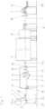
- a web 1 of paper is guided in a web travel direction according to arrow 100 through a device for impregnation/coating and, coming from a roll 2, successively runs through an impregnation unit 4, a dryer 5, a cooling device 6 and a cross cutter 7.
- the device for impregnation/coating Coating also includes a spreader roller 8, web guiding rollers 9 and a transport device 10.
- directional information such as before or after relates to the web running direction.
- the roll 2 which comprises a supply of the web 1, is rotatably mounted in an unwinder (not shown) in such a way that the web 1 can be drawn off from it.
- the roller 2 can either be driven and the web 1 is then deflected over a roller 3 .
- an infeed unit is arranged, which comprises a plurality of rollers, at least one of which can be driven.
- the impregnation unit 4 comprises an application roller 11 with a first deflection roller 14, an immersion roller 12, two metering rollers 13 and two distributor rollers 15.
- the application roller 11, the immersion roller 12, the metering rollers 13, the first deflection roller 14 and the distributor rollers 15 are mounted parallel to one another.
- the application roller 11 can be driven and is mounted within a first trough 16 in such a way that it protrudes upwards out of the first trough 16 with approximately half its circumference.
- the first trough 16 is filled with impregnating agent up to a predetermined level, so that a partial circumference of the application roller 11 is immersed in the impregnating agent.
- a small distance in front of the application roller 11, the first deflection roller 14 is mounted vertically.
- the immersion roller 12 is at a predetermined distance behind the application roller 11 vertically or approximately vertically in an upper pull-in position or in a lower immersion position - within a second trough 17 - slidably mounted.
- the spreader roller 8 is mounted in front of and above the second trough 17 in such a way that during operation it is touched by the web 1 in its upper crown region.
- the second trough 17 is filled with impregnating agent, which can be different from that in the first trough 16, in such a way that the dipping roller 12 is at least partially immersed in the impregnating agent.
- the pan roller 12 is partially wrapped around by the web 1 in a lower area.
- Two metering rollers 13 are mounted behind and above the dipping roller 12 in such a way that they form a narrow gap whose width can be adjusted.
- an upper metering roller 13 is vertically displaceable.
- the distributing rollers 15 are mounted, one of which is vertically displaceable at the front in the direction of web travel.
- the web 1 After a predetermined transport distance of e.g. 1 m behind the impregnation unit 4, the web 1 is guided into the dryer 5, where it can be subjected to energy, preferably in the form of heat, in a known manner.
- energy preferably in the form of heat
- the cooling device 6 and then the web guide rollers 9 for controlling the straight running of the web 1 are arranged.
- a rear one of the web guiding rollers 9 can be pivoted, as indicated by the double arrow.
- the cross cutter 7 with an upstream second deflection roller 18 and a sheet stacker 20 for sheets cut from the web 1 are arranged.
- the second deflection roller 18 is mounted so that it can be adjusted in height.
- the first deflection roller 14, the front distributor roller 15, the dipping roller 12, the rear web guide roller 9 and the second deflection roller 18 are all referred to as movable elements.
- the transport device 10 is guided through the entire device for impregnation. It comprises two endless guide members 10a such as chains or perforated steel strips and a magnet 22 and a magnetizable sheet metal plate 23, which together form a driver 27.
- the guide members are guided in parallel and in a straight line from an area below the roller 2 to behind the cross cutter 7, deflected here and fed back again.
- Rails and deflection rollers 21, for example, are used to guide the guide elements arranged so that an upper run 10a of the transport device 10 runs in a largely horizontal plane. At least one of the deflection rollers 21 per guide element can be driven.
- a transport direction of transport device 10 corresponds to that of web 1.
- the management organs is associated with a plate-shaped magnet 22, which consists of the Figures 3 and 4 can be seen more clearly.
- the magnet 22 can be easily clamped into the guide elements by means of a housing 22a surrounding it.
- the housing 22a has clamping pieces (known per se) on its broad sides that correspond to the guide elements.
- the cuboid magnet 22 extends between the guide members over a little more than the maximum width of the web 1 that can be processed, ie parallel to the plane of the web 1 and transverse to the transport direction.
- the housing 22a is dimensioned such that it encloses the magnet 22 with little play.
- the housing 22a is formed from a trough-like receptacle which can be closed with a cover 22b.
- the housing 22a and the cover 22b are made of non-magnetizable material such as austenitic steel or plastic.
- a first pair of collectors 24 is attached outside the width of the web 1 such that the upper ends of the collectors clearly protrude over the cover 22b.
- the first pair of collectors 24 is attached to ends of a front longitudinal side of the sheet metal plate 23 .
- the collectors 24 point downwards when the sheet metal plate is placed in one of the holders 25, 26.
- a first rest position of the magnet 22 is below the roller 2 and a second rest position between the rear distribution roller 15 and the dryer 5.
- the magnet 22 is composed of a plurality of magnetic plates, which together result in the size of the magnet 22.
- the sheet metal plate 23 is made of magnetizable material such as suitable steel. Its length and width essentially correspond to the dimensions of the magnet 22.
- the longitudinal edges of the sheet metal plate 23 are rounded, for example by grinding or by bending a strip through 180°. This avoids the risk of the web 1 being damaged or even severed by the longitudinal edges.
- a length of the sheet metal plate 23 is greater than a width of the Web 1, so that a predetermined overhang of the sheet metal plate 23 over the width of the web 1 is guaranteed on both sides.
- the sheet metal plate 23 is designed as a separating device for the web 1 .
- a longitudinal strip 23a of the sheet metal plate 23 is bent through 90°, similar to an angle profile.
- a free edge of the longitudinal strip 23a is designed either as a cutting edge or preferably jagged like a sawtooth.
- a collector 24 is formed or fastened on each broad side of the sheet metal plate 23 in accordance with the above-described alternative of the first pair.
- the two customers 24 form a second pair here.
- two holders 25, 26 are arranged in the device for impregnation, which form rest positions of the metal plate.
- the brackets 25, 26 are fastened at a short distance above the plane in which the web 1 is guided.
- a distance between the plane and a lower limit of the holders 25, 26 is 2 cm to 10 cm, for example.
- Each of the brackets 25, 26 is made, e.g. the long leg is either horizontal or slightly sloping at an angle of up to 3° in the transport direction.
- a first of the holders 25 is arranged between the roller 2 and the impregnation unit 4 .
- a second of the holders 26 is fastened between the impregnation unit 4 and the dryer 5 .
- the second rest position of the magnet 22 is between the impregnation mechanism 4 and the second holder 26.
- Pressing means 28 can be arranged between the second holder 26 and the dryer 5 . These are formed, for example, from a roller or from at least two spaced rollers. A circumference of the cylinder or of the rollers is preferably coated with an elastic covering at least over a predetermined width. A lower apex of the roller or the rollers has a distance of 2 mm to 8 mm to the plane of the web 1.
- the troughs 16 and 17 are filled with liquid resin.
- a beginning of the web 1 is pulled off the roll 2 far enough that it can be guided at least to a rear end of the first holder 25 .
- the beginning hangs freely from the roll 2.
- the first execution of the sheet metal plate 23 is inserted into the first holder 25 with the bent strips pointing upwards.
- the movable rollers are in a retracted position.
- the rear web guiding roller 9 is moved to the lower position and the first deflection roller 14, the front distributing roller 15, the dipping roller 12, the upper metering roller 13 and the second deflection roller 18 are each moved to the upper position.
- the drawing-in positions of the rollers and a path of the web 1 that deviates from normal operation are drawn in dashed lines.
- All the drivable rollers are started up at a speed corresponding to the production speed, with the application roller 11 being driven in opposite directions here.
- the dryer 5 and the cooling device 6 are put into operation and set to the required temperatures.
- a drive of the transport device 10 and the drive of the roller 2 or the infeed unit are switched on at the production speed and the magnet 22 clamped in the guide elements is thus moved in the transport direction.
- the magnet 22 drags the beginning of the web 1 hanging down.
- the pickups 24 grasp the sheet metal plate 23 so that it slides onto the cover 22b of the magnet 22 and is held by the magnetic force.
- the beginning of the web 1 is immovably clamped between the metal plate 23 and the cover 22b, so that it is pulled through the device for impregnation.
- the web 1 is unwound from the roll 2 and guided around the roller 3, with a predetermined tension of the web 1 being present.
- the first deflection roller 14 is moved to the lower position, so that the web 1 touches a partial circumference of the application roller 11 and is thus wetted with the liquid impregnating agent from the tub 16.
- the magnet 22 with the beginning of the web 1 is guided further above the spreader roller 8 and between the distributor rollers 15 . As soon as it has passed the latter, the pan roller 12, the upper metering roller 13 and the front distribution roller 15 are each moved to the lower position.
- the magnet 22 and thus the web 1 continues to run through the dryer 5, where the web 1 is dried to a predetermined residual moisture content.
- Heat in the form of, for example, hot air or infrared radiation is preferably used as the drying energy, but other energy sources such as, for example, microwaves can also be used.
- the web 1 is then cooled in the cooling device 6 . Furthermore, after passing the magnet 22, the move the rear web guiding roller 9 upwards and switch on the web guiding roller.
- the web 1 is then guided under the second deflection roller 18, which is moved to its lower position after passing the magnet 22, to the cross cutter 7, where it is cut into sheets of a predetermined length and the sheets are deposited on the sheet tray 20.
- the drive of the transport device 10 is switched off and normal operation continues.
- the draw-in speed and the production speed are essentially the same and are 0.5 to 20 m/min.
- the magnet 22 is first suspended at a point between the distributor rollers 15 and the dryer 5 in such a way that it is located in front of the second holder 26 with the sheet metal plate 23 .
- the transport device 10 is switched on at the production speed so that the magnet 22 is transported in the direction of the dryer 5 .
- the magnet 22 removes the sheet metal plate 23 by means of the second pair of pickups 24.
- the sheet metal plate 23 is held by the magnet 22 so that the web 1 is clamped between the magnet 22 and the sheet metal plate 23 at this point.
- the web 1 is separated at the rear end of the magnet 22 by the longitudinal strip 23a, if necessary with the aid of the pressing means 28, so that on the one hand a new beginning of the web 1 is created here and on the other hand an end of the web that is transported further.
- the unwinder or the infeed unit and the impregnation unit 4 are stopped and the associated movable elements are moved into their infeed positions.
- the web end is guided through the dryer 5 and on to just before the sheet stacker 20, so that the web 1 is completely treated up to the web end.
- the web 1 can accordingly be recycled without a significant amount of rejects.
- the transport device 10, the dryer 5, the web tension control 9, the cooling device 6, and the cross cutter 7 are stopped. Shortly before the end of the web reaches a mobile element, this is moved to its retracted position.
Landscapes
- Coating Apparatus (AREA)
- Application Of Or Painting With Fluid Materials (AREA)
- Treatment Of Fiber Materials (AREA)
Description
- Die Erfindung betrifft eine Anlage zum Imprägnieren einer Bahn einem Abwickler für eine Rolle der Bahn, mindestens einem Imprägnierwerk, mindestens einem Trockner, mindestens einer Kühlvorrichtung und einer Transportvorrichtung mit mindestens einem Mitnehmer für einen Anfang einer Bahn und ein Ende einer Bahn, wobei die Transportvorrichtung weitgehend in einer horizontalen Ebene von einem vorderen Bereich bis zu einem hinteren Bereich einer Anlage geführt ist.
- In der
EP 1 757 547 A2 ist eine Einziehvorrichtung für eine Warenbahn in einer Anlage beschrieben, bei der die Einziehvorrichtung eine Hilfseinrichtung umfasst. Die Hilfseinrichtung weist ein erstes Halteelement mit einem Magneten und ein zweites Halteelement zur Aufnahme eines Bahnanfangs auf. Das zweite Halteelement ist gelenkig an dem ersten befestigt und von einer Öffnungsposition in eine Schließposition klappbar. - In der Möbelindustrie und für Fußbodenlaminate werden für Sichtflächen von Holz- oder Faserplatten Dekorpapiere verwendet. Hierfür werden bedruckte Papierbahnen mit Kunstharzen wie Harnstoffharz oder Melamin imprägniert und gegebenenfalls mit abriebfesten Partikeln wie z.B. Korund versehen, um bestimmte Eigenschaften der Bahnen zu erzielen. Anschließend werden die Bahnen getrocknet und gekühlt. Teilweise werden auch unbedruckte Papiere - also Papiere ohne Dekor - verwendet. Vorrichtungen und Verfahren zur Herstellung der imprägnierten Bahnen (Imprägnate) sind aus dem Stand der Technik bekannt und z.B. in der
DE 20 2007 011 437 U1 und derDE 197 10 549 A1 beschrieben. - Hersteller der Möbel und/oder Laminate gehen dazu über, ihre Lagerhaltung drastisch zu reduzieren. Das bedeutet, dass sie relativ kleine Mengen eines bestimmten Dekors bestellen, das zu einem bestimmten Zeitpunkt zu liefern ist.
- Das Imprägnieren bzw. Beschichten von Papierbahnen ist mit den bekannten Verfahren und Anlagen für geringe Mengen sehr aufwändig. Insbesondere sind die Produktion von Ausschuss beim An- und Abfahren der Vorrichtungen sowie der Arbeitsaufwand sehr hoch. So muss die Bahn zunächst von Hand in ein Imprägnierwerk und gegebenenfalls durch Imprägnierbäder eingefädelt werden. Die Bahn wird imprägniert und so lange verworfen, bis ein ausreichendes Imprägnierergebnis vorliegt. Erst dann wird die Bahn durchtrennt und der so entstandene neue Anfang der Bahn mittels einer Einziehvorrichtung durch einen Trockner und eine Kühlvorrichtung geführt. Auch hinter diesen Vorrichtungen fällt zunächst wieder Ausschuss an, bis ein zufriedenstellendes Endergebnis der Bahnqualität erzielt ist. Erst dann beginnt die Produktion von brauchbarem Imprägnat, das zu Bogen geschnitten oder aufgewickelt wird. Gegebenenfalls müssen die gewünschten Imprägnierungs-/ Beschichtungsmittel zusammengestellt und gegen die in der Anlage vorhandenen ausgetauscht werden. Hierfür sind relativ große Harzmengen von ca. 800 I erforderlich. Die Rüstzeit für die Vorbereitung beträgt mehr als eine Stunde. Insgesamt sind also die Kosten für Arbeit und Ausschuss beim An- und Abfahren hoch. Daher sind die Imprägnierbetriebe nicht in der Lage, geringe Mengen Imprägnat wirtschaftlich anzubieten, und sind gezwungen, solche Aufträge abzulehnen oder mit Verlust durchzuführen. Die Geschwindigkeiten der Bahn während des Einfädelns und des Einziehens sind sehr viel kleiner als die Produktionsgeschwindigkeit.
- Ein Ansatz zur Lösung des oben beschriebenen Problems ist in der
DE 10 2009 021 164 A1 beschrieben. Hier wird vorgeschlagen, eine Einziehvorrichtung für eine Bahn von einem Bereich vor einem Imprägnierwerk bis hinter eine Kühlvorrichtung in einer horizontalen Ebene zu führen. - Der Begriff Imprägnierwerk bedeutet im Sinn der Erfindung eine Vorrichtung zum Auftragen von Harz auf eine Bahn, unabhängig von der Art des Auftrags - z.B. Tauchen, Besprühen oder Beschichten - und von der Funktion, ob das Harz zum Imprägnieren oder zum Beschichten (z.B. einer vorbehandelten Bahn) aufgetragen wird. Entsprechend ist der Begriff "imprägnieren" verwendet.
- Aufgabe der Erfindung ist es, eine Anlage zum Imprägnieren mit einer Transportvorrichtung für einen Anfang einer Bahn und ein Ende einer Bahn so zu verbessern, dass bei geringem Aufwand und minimalem Ausschuss kleinere Mengen von imprägniertem Dekorpapier hergestellt werden können.
- Die Aufgabe ist durch die Merkmale des Anspruchs 1 gelöst. Der Mitnehmer umfasst einen plattenförmigen Magneten, der unterhalb der Bahn geführt ist, sich über mindestens die Breite der Bahn erstreckt und im Betrieb der Transportvorrichtung mit einer magnetisierbaren Blechplatte zusammenwirkt, die oberhalb der Bahn aus einer Ruheposition in eine Halteposition bewegbar ist.
- Hierdurch ist es einerseits möglich, die Bahn automatisch in die komplette Vorrichtung einzuziehen. Es ist lediglich ein Anfang der Bahn in ausreichender Länge frei hängend von einer Rolle zur Verfügung zu stellen. Der Anfang wird dann zwischen dem Magneten und der Blechplatte eingeklemmt und kann durch die Transportvorrichtung bis hinter den Querschneider gebracht werden. Weiterhin kann nach Erreichen der erforderlichen Produktionsmenge ein Ende der Bahn mittels der Transportvorrichtung bis hinter den Trockner geführt werden. Hierfür sind vorher, z.B. während des Betriebs der Vorrichtung, der Magnet und die Blechplatte in ihre zweiten Ausgangspositionen zu verbringen. Der Aufwand für die Bedienung wird weiter vermindert. Insgesamt kann die Bahn weitgehend vollständig behandelt und verwertet werden. Die Produktion von Ausschuss wird fast vollständig vermieden, so dass insgesamt auch kleinere Mengen von Imprägnat wirtschaftlich erzeugt werden können. Die Vorrichtung kann durch eine Person bedient werden.
- Eine erste Ruheposition ist in einem Bereich zwischen einem Abwickler und einem Imprägnierwerk sowie eine zweite Ruheposition zwischen dem Imprägnierwerk und einem Trockner angeordnet. Hierdurch lässt sich einerseits ein Anfang der Bahn sicher und automatisch durch die komplette Imprägnieranlage einziehen und anderseits ein Ende der imprägnierten Bahn bis zu einem Querschneider führen, so dass besonders wenig Ausschuss anfällt.
- Die Unteransprüche betreffen die vorteilhafte Ausgestaltung der Erfindung.
- In einer Ausgestaltung ist der Magnet aus einer Vielzahl von Einzelplatten zusammengesetzt. Hierdurch ist der Magnet mechanisch weniger empfindlich, preiswerter erhältlich und einfacher in die Vorrichtung zu montieren.
- In einer weiteren Ausgestaltung ist der Magnet in einem Gehäuse gelagert, das mindestens ein erstes Paar Abnehmer für die Blechplatte aufweist. Das Gehäuse ist vorzugsweise aus nicht magnetisierbarem Material gefertigt, schützt den mechanisch empfindlichen Magneten vor z.B. Zerbrechen und gewährleitstet die gewohnte Funktion auch bei einem Bruch. Insbesondere können die Einzelplatten sicher und in vorbestimmter Position angeordnet werden.
- In einer weiteren Ausgestaltung ist ein zweites Paar der Abnehmer an der Blechplatte angeordnet. Hierdurch können unterschiedlich ausgebildete Blechplatten selektiv abgenommen werden.
- In einer weiteren Ausgestaltung ist der Magnet mit einer Abdeckung aus nicht magnetisierbarem Material versehen. Hierdurch ist der Magnet vor der im Betrieb aufschlagenden Blechplatte geschützt, so dass die Haltbarkeit des Magneten gewährleistet ist, ohne das Magnetfeld zu beeinträchtigen.
- In einer weiteren Ausgestaltung weist eine für die zweite Ruheposition vorgesehene zweite Blechplatte eine Trennvorrichtung für die Bahn auf. Hierdurch erfolgt die erforderliche Trennung der Bahn selbsttätig.
- In einer weiteren Ausgestaltung sind der zweiten Ruheposition Andrückmittel zum Anpressen der Blechplatte auf den Magneten zugeordnet. Dies gewährleistet das sichere Durchtrennen auch stabilerer Bahnen.
- Die Erfindung wird anhand der vereinfacht dargestellten Zeichnung am Beispiel einer Imprägnieranlage weiter erläutert. Es zeigen
-
Figur 1 ein Schema einer erfindungsgemäßen Vorrichtung im Längsschnitt, -
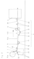
Figur 2 einen vorderen Abschnitt des Schemas derFigur 1 als Detail, -
Figur 3 einen Teil einer Transportvorrichtung für einen Anfang einer Bahn, -
Figur 4 eine Alternative der Transportvorrichtung und -
Figur 5 ein als Trennvorrichtung für die Bahn ausgebildetes Blech. - Nach den
Figuren 1 und2 ist eine Bahn 1 aus Papier in einer Bahnlaufrichtung gemäß Pfeil 100 durch eine Vorrichtung zum Imprägnieren/Beschichten geführt und durchläuft hierbei von einer Rolle 2 kommend nacheinander ein Imprägnierwerk 4, einen Trockner 5, eine Kühlvorrichtung 6 und einen Querschneider 7. Die Vorrichtung zum Imprägnieren/ Beschichten umfasst weiterhin eine Breitstreckwalze 8, Bahnlaufregelwalzen 9 und eine Transportvorrichtung 10. - Richtungsangaben wie vor oder hinter beziehen sich in dieser Anmeldung auf die Bahnlaufrichtung.
- Die Rolle 2, die einen Vorrat der Bahn 1 umfasst, ist in einem nicht dargestellten Abwickler drehbar so gelagert, dass die Bahn 1 von ihr abgezogen werden kann. Die Rolle 2 ist entweder antreibbar, und die Bahn 1 ist dann über eine Walze 3 umgelenkt. Oder zwischen der Rolle 2 und dem Imprägnierwerk 4 ist ein Einzugswerk angeordnet, das mehrere Walzen umfasst, von denen mindestens eine antreibbar ist.
- Das Imprägnierwerk 4 umfasst eine Antragswalze 11 mit einer ersten Umlenkwalze 14, eine Tauchwalze 12, zwei Dosierwalzen 13 und zwei Verreibewalzen 15. Die Antragswalze 11, die Tauchwalze 12, die Dosierwalzen 13, die erste Umlenkwalze 14 und die Verreibewalzen 15 sind parallel zueinander gelagert.
- Die Antragswalze 11 ist antreibbar und so innerhalb einer ersten Wanne 16 gelagert, dass sie in etwa mit ihrem halben Umfang nach oben aus der ersten Wanne 16 herausragt. Die erste Wanne 16 ist im Betrieb bis zu einem vorbestimmten Füllstand mit Imprägniermittel gefüllt, so dass ein Teilumfang der Antragswalze 11 in das Imprägniermittel taucht. In geringem Abstand vor der Antragswalze 11 ist die erste Umlenkwalze 14 vertikal verschiebbar gelagert.
- Die Tauchwalze 12 ist in vorbestimmtem Abstand hinter der Antragswalze 11 vertikal oder annähernd vertikal in eine obere Einziehposition oder in eine untere Tauchposition - innerhalb einer zweiten Wanne 17 - verschiebbar gelagert. Vor und oberhalb der zweiten Wanne 17 ist die Breitstreckwalze 8 so gelagert, dass sie im Betrieb von der Bahn 1 in ihrem oberen Scheitelbereich berührt wird. Die zweite Wanne 17 ist im Betrieb mit Imprägniermittel, das von dem in der ersten Wanne 16 unterschiedlich sein kann, so gefüllt, dass die Tauchwalze 12 zumindest teilweise in das Imprägniermittel taucht. Hierbei ist die Tauchwalze 12 von der Bahn 1 teilweise in einem unteren Bereich umschlungen.
- Hinter und oberhalb der Tauchwalze 12 sind zwei Dosierwalzen 13 so gelagert, dass sie einen engen, in der Weite einstellbaren Spalt bilden. Hierfür ist eine obere der Dosierwalzen 13 vertikal verschiebbar.
- Hinter den Dosierwalzen 13 sind die Verreibewalzen 15 gelagert, von denen eine in Bahnlaufrichtung vordere vertikal verschiebbar ist.
- Nach einer vorbestimmten Transportstrecke von z.B. 1 m hinter dem Imprägnierwerk 4 ist die Bahn 1 in den Trockner 5 geführt, wo sie in bekannter Weise mit Energie vorzugsweise in Form von Wärme beaufschlagbar ist.
- Hinter dem Trockner 5 sind die Kühlvorrichtung 6 und dann die Bahnlaufregelwalzen 9 zum Regeln des Geradeauslaufs der Bahn 1 angeordnet. Eine hintere der Bahnlaufregelwalzen 9 ist verschwenkbar, wie durch Doppelpfeil angedeutet ist.
- Schließlich sind der Querschneider 7 mit vorgeschalteter zweiter Umlenkwalze 18 und eine Bogenablage 20 für aus der Bahn 1 geschnittene Bogen angeordnet. Die zweite Umlenkwalze 18 ist höhenverstellbar gelagert.
- Gemäß diesem Ausführungsbeispiel sind die erste Umlenkwalze 14, die vordere Verreibewalze 15, die Tauchwalze 12, die hintere Bahnlaufregelwalze 9 und die zweite Umlenkwalze 18 insgesamt als verfahrbare Elemente bezeichnet.
- Es ist selbstverständlich, dass alle Walzen mit Ausnahme der Bahnlaufregelwalzen 9 parallel zueinander und zu der Ebene der Bahn 1 sind.
- Die Transportvorrichtung 10 ist durch die gesamte Vorrichtung zum Imprägnieren geführt. Sie umfasst zwei endlose Führungsorgane 10a wie z.B. Ketten oder gelochte Stahlbänder sowie einen Magneten 22 und eine magnetisierbare Blechplatte 23, die zusammen einen Mitnehmer 27 bilden. Die Führungsorgane sind parallel und geradlinig von einem Bereich unterhalb der Rolle 2 bis hinter den Querschneider 7 geführt, hier umgelenkt und wieder zurückgeführt. Zum Führen der Führungsorgane sind z.B. Schienen und Umlenkrollen 21 so angeordnet, dass ein Obertrum 10a der Transportvorrichtung 10 in einer weitgehend horizontalen Ebene verläuft. Mindestens eine der Umlenkrollen 21 pro Führungsorgan ist antreibbar. Eine Transportrichtung der Transportvorrichtung 10 entspricht derjenigen der Bahn 1.
- Den Führungsorganen ist ein plattenförmiger Magnet 22 zugeordnet, der aus den
Figuren 3 und 4 deutlicher zu erkennen ist. Der Magnet 22 ist mittels eines ihn umgebenden Gehäuses 22a in die Führungsorgane leicht klemmend einhängbar. Hierfür weist das Gehäuse 22a an seinen Breitseiten mit den Führungsorganen korrespondierende (an sich bekannte) Klemmstücke auf. Im eingehängten Zustand erstreckt sich der quaderförmige Magnet 22 zwischen den Führungsorganen über etwas mehr als die maximal verarbeitbare Breite der Bahn 1, also parallel zu der Ebene der Bahn 1 und quer zu der Transportrichtung. Das Gehäuse 22a ist so bemessen, dass es den Magneten 22 mit geringem Spiel umschließt. Das Gehäuse 22a ist aus einer trogartigen Aufnahme gebildet, die mit einer Abdeckung 22b verschließbar ist. Das Gehäuse 22a und die Abdeckung 22b sind aus nicht magnetisierbarem Material wie z.B. austenitischem Stahl oder Kunststoff gefertigt. An einem in der Transportrichtung hinteren Ende des Gehäuses 22a und damit indirekt an der hinteren Längsseite des Magneten 22 ist ein erstes Paar Abnehmer 24 so außerhalb der Breite der Bahn 1 befestigt, dass obere Enden der Abnehmer deutlich über die Abdeckung 22b herausragen. - In einer alternativen Ausbildung ist das erste Paar der Abnehmer 24 an Enden einer vorderen Längsseite der Blechplatte 23 befestigt. Die Abnehmer 24 weisen nach unten, wenn die Blechplatte in eine der Halterungen 25, 26 eingelegt ist.
- Eine erste Ruheposition des Magneten 22 befindet sich unterhalb der Rolle 2 und eine zweite Ruheposition zwischen der hinteren Verreibewalze 15 und dem Trockner 5.
- In einer Alternative ist der Magnet 22 aus einer Vielzahl von Magnetplatten zusammengesetzt, die insgesamt die Größe des Magneten 22 ergibt.
- Die Blechplatte 23 ist aus magnetisierbarem Material wie z.B. entsprechendem Stahl gefertigt. Seine Länge und Breite entsprechen im Wesentlichen den Abmessungen des Magneten 22.
- In einer ersten Ausführung, die in der
Figur 3 dargestellt ist, sind Längskanten der Blechplatte 23 gerundet, z.B. durch Schleifen oder durch Umbiegen eines Streifens um 180°. Hierdurch wird die Gefahr vermieden, dass die Bahn 1 durch die Längskanten geschädigt oder sogar durchtrennt wird. Eine Länge der Blechplatte 23 ist größer als eine Breite der Bahn 1, so dass beidseitig ein vorbestimmter Überstand der Blechplatte 23 über die Breite der Bahn 1 gewährleistet ist. - In einer zweiten Ausführung, die in den
Figuren 4 und5 dargestellt ist, ist die Blechplatte 23 als Trennvorrichtung für die Bahn 1 ausgebildet. Hierfür ist ein Längsstreifen 23a der Blechplatte 23 um 90° umgebogen, ähnlich einem Winkelprofil. Eine freie Kante des Längsstreifens 23a ist entweder als Schneide oder vorzugsweise sägezahnartig gezackt ausgebildet. Im Bereich der Längsseite der Blechplatte 23, die dem Längsstreifen 23a gegenüber liegt, ist entsprechend der oben beschriebenen Alternative des ersten Paares an jeder Breitseite der Blechplatte 23 ein Abnehmer 24 ausgebildet oder befestigt. Die beiden Abnehmer 24 bilden hier ein zweites Paar. - Für die Blechplatte 23 sind zwei Halterungen 25, 26 in der Vorrichtung zum Imprägnieren angeordnet, die Ruhepositionen der Blechplatte bilden. Die Halterungen 25, 26 sind mit kurzem Abstand oberhalb der Ebene befestigt, in der die Bahn 1 geführt ist. Ein Abstand zwischen der Ebene und einer unteren Begrenzung der Halterungen 25, 26 beträgt z.B. 2 cm bis 10 cm. Jede der Halterungen 25, 26 ist z.B. aus einem Winkelprofil gefertigt, dessen kurzer Schenkel an einem hinteren Ende des Winkelprofils senkrecht oder schwach nach vorne geneigt nach oben weist; der lange Schenkel ist also entweder waagerrecht oder leicht mit einem Winkel von bis zu 3° in Transportrichtung abfallend.
- Eine erste der Halterungen 25 ist zwischen der Rolle 2 und dem Imprägnierwerk 4 angeordnet.
- Eine zweite der Halterungen 26 ist zwischen dem Imprägnierwerk 4 und dem Trockner 5 befestigt. Die zweite Ruheposition des Magneten 22 befindet sich zwischen dem Imprägnierwerk 4 und der zweiten Halterung 26.
- Zwischen der zweiten Halterung 26 und dem Trockner 5 können Andrückmittel 28 angeordnet sein. Diese sind z.B. aus einer Walze oder aus mindestens zwei beabstandeten Rollen gebildet. Vorzugsweise ist ein Umfang der Walze beziehungsweise der Rollen zumindest über eine vorbestimmte Breite mit einem elastischen Belag beschichtet. Ein unterer Scheitelpunkt der Walze beziehungsweise der Rollen weist einen Abstand von 2 mm bis 8 mm zu der Ebene der Bahn 1 auf.
- Zur Inbetriebnahme der Vorrichtung zum Imprägnieren werden die Wannen 16 und 17 mit flüssigem Harz gefüllt. Ein Anfang der Bahn 1 wird so weit von der Rolle 2 abgezogen, dass er mindestens bis zu einem hinteren Ende der ersten Halterung 25 geführt werden kann. Der Anfang hängt frei von der Rolle 2 herab. Die erste Ausführung der Blechplatte 23 ist in die erste Halterung 25 eingelegt, wobei die umgebogenen Streifen nach oben weisen.
- Die verfahrbaren Walzen sind in einer Einzugsposition. Hierfür sind die hintere Bahnlaufregelwalze 9 in die untere Position sowie die erste Umlenkwalze 14, die vordere Verreibewalze 15, die Tauchwalze 12, die obere Dosierwalze 13 und die zweite Umlenkwalze 18 jeweils in die obere Position verfahren. Die Einzugspositionen der Walzen und ein vom Normalbetrieb abweichender Weg der Bahn 1 sind gestrichelt gezeichnet.
- Alle antreibbaren Walzen werden mit einer der Produktionsgeschwindigkeit entsprechenden Drehzahl angefahren, wobei die Antragswalze 11 hier gegenläufig angetrieben ist. Der Trockner 5 und die Kühlvorrichtung 6 werden in Betrieb gesetzt und auf die erforderlichen Temperaturen eingestellt. Sobald diese erreicht sind, wird ein Antrieb der Transportvorrichtung 10 sowie der Antrieb der Rolle 2 beziehungsweise des Einzugswerks mit der Produktionsgeschwindigkeit eingeschaltet und so der in die Führungsorgane eingeklemmte Magnet 22 in der Transportrichtung bewegt. Hierbei schleppt der Magnet 22 den herunterhängenden Anfang der Bahn 1 mit. Sobald der Magnet 22 unter die erste Halterung 25 gerät, erfassen die Abnehmer 24 die Blechplatte 23, so dass diese auf die Abdeckung 22b des Magneten 22 gleitet und durch die Magnetkraft gehalten wird. Hierbei ist der Anfang der Bahn 1 zwischen der Blechplatte 23 und der Abdeckung 22b unverrückbar eingeklemmt, so dass er durch die Vorrichtung zum Imprägnieren gezogen wird. Hierbei wird die Bahn 1 von der Rolle 2 abgewickelt und um die Walze 3 geführt, wobei eine vorbestimmte Spannung der Bahn 1 vorhanden ist.
- Nachdem der Magnet 22 die Antragswalze 11 passiert hat, wird die erste Umlenkwalze 14 in die untere Position verfahren, so dass die Bahn 1 einen Teilumfang der Antragswalze 11 berührt und auf diese Weise mit dem flüssigen Imprägniermittel aus der Wanne 16 benetzt wird.
- Der Magnet 22 mit dem Anfang der Bahn 1 wird weiter oberhalb der Breitstreckwalze 8 und zwischen den Verreibewalzen 15 geführt. Sobald er die letzteren passiert hat, werden die Tauchwalze 12, die obere Dosierwalze 13 und die vordere Verreibewalze 15 jeweils in die untere Position verfahren.
- Der Magnet 22 und somit die Bahn 1 durchläuft weiter den Trockner 5, wo die Bahn 1 auf eine vorbestimmte Restfeuchte getrocknet wird. Als Trocknungsenergie wird bevorzugt Wärme in Form von z.B. Heißluft oder Infrarotstrahlung verwendet, es sind aber auch andere Energiequellen wie z.B. Mikrowellen einsetzbar. Anschließend wird die Bahn 1 in der Kühlvorrichtung 6 gekühlt. Weiterhin wird nach dem Passieren des Magneten 22 die hintere Bahnlaufregelwalze 9 nach oben verfahren und die Bahnlaufregelung eingeschaltet.
- Die Bahn 1 wird dann unter die zweite Umlenkwalze 18, die nach dem Passieren des Magneten 22 in ihre untere Position verfahren wird, zu dem Querschneider 7 geführt, wo sie zu Bogen vorbestimmter Länge geschnitten wird und die Bogen auf der Bogenablage 20 abgelegt werden. Sobald der Magnet 22 den Anfang der Bogenablage 20 erreicht hat, wird der Antrieb der Transportvorrichtung 10 ausgeschaltet, und der normale Betrieb läuft weiter. Hierbei sind die Einziehgeschwindigkeit und die Produktionsgeschwindigkeit im Wesentlichen gleich und betragen 0,5 bis 20 m/min.
- Zum Abfahren der Vorrichtung zum Imprägnieren wird zunächst der Magnet 22 an einer Stelle zwischen den Verreibewalzen 15 und dem Trockner 5 so eingehängt, dass er sich vor der zweiten Halterung 26 mit der Blechplatte 23 befindet. Die Transportvorrichtung 10 wird mit der Produktionsgeschwindigkeit eingeschaltet, so dass der Magnet 22 in Richtung des Trockners 5 transportiert wird. Hierbei entnimmt der Magnet 22 die Blechplatte 23 mittels des zweiten Paars Abnehmer 24. Die Blechplatte 23 wird durch den Magneten 22 gehalten, so dass die Bahn 1 an dieser Stelle zwischen dem Magneten 22 und der Blechplatte 23 eingeklemmt ist. Gleichzeitig wird die Bahn 1 am hinteren Ende des Magneten 22 durch den Längsstreifen 23a, gegebenenfalls mit Hilfe des Andrückmittels 28 getrennt, so dass hier einerseits ein neuer Anfang der Bahn 1 entsteht und andererseits ein Bahnende, das weiter transportiert wird. Der Abwickler beziehungsweise das Einzugswerk und das Imprägnierwerk 4 werden gestoppt und die zugehörigen verfahrbaren Elemente in ihre Einzugspositionen verfahren.
- Das Bahnende wird durch den Trockner 5 und weiter bis kurz vor die Bogenablage 20 geführt, so dass die Bahn 1 bis zu dem Bahnende vollständig behandelt wird. Die Bahn 1 kann entsprechend ohne wesentlichen Anfall von Ausschuss verwertet werden. Die Transportvorrichtung 10, der Trockner 5, die Bahnzugregelung 9, die Kühlvorrichtung 6, und der Querschneider 7 werden gestoppt. Jeweils kurz bevor das Bahnende ein verfahrbares Element erreicht, wird dieses in seine Einzugsposition verfahren.
- Nicht verwertbare Reste der Bahn 1 werden entfernt, und falls erforderlich wird die Vorrichtung zum Imprägnieren/Beschichten entleert und gereinigt. Sie steht dann zum Imprägnieren einer neuen Bahn 1 zur Verfügung.
-
1 Bahn 2 Rolle 3 Walze 4 Imprägnierwerk 5 Trockner 6 Kühlvorrichtung 7 Querschneider 8 Breitstreckwalze 9 Bahnlaufregelwalze 10 Transportvorrichtung 10a Führungsorgan 11 Antragswalze 12 Tauchwalze 13 Dosierwalze 14 erste Umlenkwalze 15 Verreibewalze 16 erste Wanne 17 zweite Wanne 18 zweite Umlenkwalze 20 Stapel 21 Umlenkrolle 22 Magnet 22a Gehäuse 22b Abdeckung 23 Blechplatte 23a Längsstreifen 24 Abnehmer 25 erste Halterung 26 zweite Halterung 27 Mitnehmer 28 Andrückmittel
Claims (7)
- Anlage zum Imprägnieren einer Bahn (1) miteinem Abwickler für eine Rolle (2) der Bahn (1),mindestens einem Imprägnierwerk (4),mindestens einem Trockner (5),mindestens einer Kühlvorrichtung (6) undeiner Transportvorrichtung (10) mit mindestens einem Mitnehmer (27) für einen Anfang einer Bahnund ein Ende einer Bahn (1), wobei die Transportvorrichtung (10) in einer horizontalen Ebene von einem vorderen Bereich bis zu einem hinteren Bereich einer Anlage geführt ist,wobeider Mitnehmer (27) einen plattenförmigen Magneten (22) umfasst, der beim Betrieb der Transportvorrichtung (10) unterhalb der Bahn (1) geführt ist, sich über mindestens die Breite der Bahn (1) erstreckt und im Betrieb der Transportvorrichtung (10) mit einer magnetisierbaren Blechplatte (23) zusammenwirkt, die oberhalb der Bahn (1) aus einer Ruheposition in eine Halteposition bewegbar ist, wobei eine erste Ruheposition der Blechplatte (23) in einem Bereich zwischen dem Abwickler und dem Imprägnierwerk (4) sowie eine zweite Ruheposition zwischen dem Imprägnierwerk (4) und dem Trockner (5) angeordnet sind.
- Anlage nach Anspruch 1, wobei der Magnet (22) aus einer Vielzahl von Einzelplatten zusammengesetzt ist.
- Anlage nach Anspruch 1 oder 2, wobei der Magnet (22) in einem Gehäuse (22a) gelagert ist, das ein erstes Paar Abnehmer (24) für die Blechplatte (23) aufweist.
- Anlage nach Anspruch 3, wobei ein zweites Paar Abnehmer (24) an der Blechplatte (23) angeordnet ist.
- Anlage nach einem der Ansprüche 1 bis 4, wobei der Magnet (22) mit einer Abdeckung (22b) aus nicht magnetisierbarem Material versehen ist.
- Anlage nach einem der Anspruche 1 bis 5, wobei eine für die zweite Ruheposition vorgesehene zweite Blechplatte (23) eine Trennvorrichtung (23a) für die Bahn (1) aufweist.
- Anlage nach Anspruch 6, wobei der zweiten Ruheposition Andrückmittel zum Anpressen der Blechplatte (23) auf den Magneten (22) zugeordnet sind.
Applications Claiming Priority (2)
| Application Number | Priority Date | Filing Date | Title |
|---|---|---|---|
| DE102015106747.1A DE102015106747B3 (de) | 2015-04-30 | 2015-04-30 | Transportvorrichtung für eine Warenbahn |
| PCT/EP2016/058172 WO2016173850A1 (de) | 2015-04-30 | 2016-04-14 | Transportvorrichtung für eine warenbahn |
Publications (2)
| Publication Number | Publication Date |
|---|---|
| EP3288877A1 EP3288877A1 (de) | 2018-03-07 |
| EP3288877B1 true EP3288877B1 (de) | 2023-07-05 |
Family
ID=55754277
Family Applications (1)
| Application Number | Title | Priority Date | Filing Date |
|---|---|---|---|
| EP16716552.1A Active EP3288877B1 (de) | 2015-04-30 | 2016-04-14 | Anlage zum imprägnieren |
Country Status (5)
| Country | Link |
|---|---|
| US (1) | US10246286B2 (de) |
| EP (1) | EP3288877B1 (de) |
| CA (1) | CA2983054A1 (de) |
| DE (1) | DE102015106747B3 (de) |
| WO (1) | WO2016173850A1 (de) |
Families Citing this family (5)
| Publication number | Priority date | Publication date | Assignee | Title |
|---|---|---|---|---|
| PL3392029T3 (pl) | 2017-04-21 | 2022-04-25 | Held Technologie Gmbh | Podajnik do dwutaśmowej prasy, układ dwutaśmowej prasy i sposób użytkowania |
| US11400479B1 (en) * | 2020-04-03 | 2022-08-02 | Michael A. Ellis | Adhesive applicator control system |
| DE102021123733A1 (de) * | 2021-09-14 | 2023-03-16 | Vits Technology Gmbh | Verfahren zum Beschichten einer bedruckten Warenbahn |
| CN217774594U (zh) * | 2022-05-05 | 2022-11-11 | 宁德时代新能源科技股份有限公司 | 涂布系统 |
| US12427711B1 (en) * | 2023-05-02 | 2025-09-30 | Red Bud Industries, Inc. | Sheet metal processing cell for applying web material to a surface of sheet metal and method thereof |
Family Cites Families (8)
| Publication number | Priority date | Publication date | Assignee | Title |
|---|---|---|---|---|
| US2936171A (en) * | 1960-05-10 | Sheet feeding apparatus | ||
| DE19710549C2 (de) * | 1997-03-14 | 1999-01-28 | Vits Maschinenbau Gmbh | Verfahren und Anlage zum Imprägnieren und Trocknen einer durchlaufenden Bahn |
| EP1101720B1 (de) * | 1999-10-21 | 2004-09-22 | Vits Verwaltungs GmbH | Anlage zum Trocknen und Kühlen und zum anschliessenden Aufwickeln oder Querschneiden einer Papierbahn |
| US20040122391A1 (en) * | 2002-12-23 | 2004-06-24 | Kimberly-Clark Worldwide, Inc. | Apparatus and method for magnetically controlling a moving web of material |
| DE102005038671A1 (de) * | 2005-08-16 | 2007-02-22 | Voith Patent Gmbh | Vorrichtung zum Führen einer Bahn |
| DE202007011437U1 (de) * | 2007-07-25 | 2007-10-25 | Vits Systems Gmbh | Vorrichtung zum Imprägnieren einer durchlaufenden Bahn |
| DE102009021164B4 (de) * | 2009-05-13 | 2013-01-03 | Vits Technology Gmbh | Verfahren und Vorrichtung zum Imprägnieren einer Bahn |
| WO2012126816A1 (de) * | 2011-03-23 | 2012-09-27 | Vits Technology Gmbh | Vorrichtung und verfahren zum imprägnieren einer papierbahn |
-
2015
- 2015-04-30 DE DE102015106747.1A patent/DE102015106747B3/de active Active
-
2016
- 2016-04-14 CA CA2983054A patent/CA2983054A1/en not_active Abandoned
- 2016-04-14 US US15/557,079 patent/US10246286B2/en active Active
- 2016-04-14 EP EP16716552.1A patent/EP3288877B1/de active Active
- 2016-04-14 WO PCT/EP2016/058172 patent/WO2016173850A1/de not_active Ceased
Also Published As
| Publication number | Publication date |
|---|---|
| EP3288877A1 (de) | 2018-03-07 |
| CA2983054A1 (en) | 2016-11-03 |
| US20180065824A1 (en) | 2018-03-08 |
| US10246286B2 (en) | 2019-04-02 |
| WO2016173850A1 (de) | 2016-11-03 |
| DE102015106747B3 (de) | 2016-06-23 |
Similar Documents
| Publication | Publication Date | Title |
|---|---|---|
| DE3314289C2 (de) | Verfahren zum Umwickeln eines sich drehenden Ballens aus Wickelmaterial, insbesondere aus einer kaschierten Mineralfaserbahn, mit einer Schutzbahn zur Verpackung, sowie Vorrichtung zur Durchführung des Verfahrens | |
| DE102015106747B3 (de) | Transportvorrichtung für eine Warenbahn | |
| WO2012126816A1 (de) | Vorrichtung und verfahren zum imprägnieren einer papierbahn | |
| EP2512690B1 (de) | Verfahren und vorrichtung zum elektrostatischen abscheiden von overspray | |
| EP0360108B1 (de) | Verfahren und Vorrichtung zum Spenden von Etiketten | |
| EP2425056A1 (de) | Anlage und verfahren zum bearbeiten einer papierbahn, insbesondere einer zigarettenpapierbahn | |
| DE19901525A1 (de) | Verfahren und Anlage zum Imprägnieren und Beschichten von Papier | |
| DE1288056B (de) | Vorrichtung zum Herstellen einer flexiblen, textlien, ungewebten Faserstoffbahn | |
| DE3301816A1 (de) | Vorrichtung zum zufuehren folienartigen materials in einen walzenspalt | |
| DE102013007602A1 (de) | Verfahren zur Herstellung einer bedruckbaren ein- oder mehrschichtigen Materialbahn sowie eine danach hergestellte Materialbahn und eine zugehörige Anlage zur Herstellung einer derartigen Materialbahn | |
| DE10057597A1 (de) | Vorrichtung zum Speichern und Abwickeln von Materialrollen in Buchbindereimaschinen | |
| DE102009021164B4 (de) | Verfahren und Vorrichtung zum Imprägnieren einer Bahn | |
| EP2277630B1 (de) | Vorrichtung zum Beschichten einer durchlaufenden Bahn | |
| EP2844797B1 (de) | Verfahren zum beschichten einer papierbahn | |
| DE19652449A1 (de) | Vorrichtung zum Verpacken einer Materialbahnrolle mit einer Verpackungsbahn | |
| DE102013105709A1 (de) | Vorrichtung zum Beschichten und/oder Imprägnieren einer textilen Warenbahn | |
| DE102008029861A1 (de) | Vorrichtung und Verfahren zum Bedrucken und Imprägnieren/Beschichten einer Bahn | |
| DE202007011437U1 (de) | Vorrichtung zum Imprägnieren einer durchlaufenden Bahn | |
| EP0270109A2 (de) | Verfahren und Vorrichtung zum Recken von Materialbahnen, insbesondere Deckelfolienbahnen für Verpackungsbehältnisse | |
| EP2950937B1 (de) | Vorrichtung zum auftragen einer beschichtung, insbesondere klebstoff, vorzugsweise leim, auf eine materialbahn | |
| DE19882815B4 (de) | Bahnzuführvorrichtung und Verfahren zum Zuführen eines Bahnendes | |
| DE202012104934U1 (de) | Vorrichtung zur Aufnahme von Beschichtungsmaterial | |
| DE102007035140B4 (de) | Vorrichtung zum Imprägnieren einer durchlaufenden Bahn | |
| DE69101808T2 (de) | Klebstoffauftrageinrichtung für durchlaufende Warenbahnen in einem Apparat zur Herstellung von Papiererzeugnissen. | |
| EP0369348B1 (de) | Vorrichtung zum Aufbringen eines Leimstreifens |
Legal Events
| Date | Code | Title | Description |
|---|---|---|---|
| STAA | Information on the status of an ep patent application or granted ep patent |
Free format text: STATUS: THE INTERNATIONAL PUBLICATION HAS BEEN MADE |
|
| PUAI | Public reference made under article 153(3) epc to a published international application that has entered the european phase |
Free format text: ORIGINAL CODE: 0009012 |
|
| STAA | Information on the status of an ep patent application or granted ep patent |
Free format text: STATUS: REQUEST FOR EXAMINATION WAS MADE |
|
| 17P | Request for examination filed |
Effective date: 20171130 |
|
| AK | Designated contracting states |
Kind code of ref document: A1 Designated state(s): AL AT BE BG CH CY CZ DE DK EE ES FI FR GB GR HR HU IE IS IT LI LT LU LV MC MK MT NL NO PL PT RO RS SE SI SK SM TR |
|
| AX | Request for extension of the european patent |
Extension state: BA ME |
|
| DAV | Request for validation of the european patent (deleted) | ||
| DAX | Request for extension of the european patent (deleted) | ||
| STAA | Information on the status of an ep patent application or granted ep patent |
Free format text: STATUS: EXAMINATION IS IN PROGRESS |
|
| 17Q | First examination report despatched |
Effective date: 20210610 |
|
| GRAP | Despatch of communication of intention to grant a patent |
Free format text: ORIGINAL CODE: EPIDOSNIGR1 |
|
| STAA | Information on the status of an ep patent application or granted ep patent |
Free format text: STATUS: GRANT OF PATENT IS INTENDED |
|
| INTG | Intention to grant announced |
Effective date: 20230302 |
|
| GRAS | Grant fee paid |
Free format text: ORIGINAL CODE: EPIDOSNIGR3 |
|
| GRAA | (expected) grant |
Free format text: ORIGINAL CODE: 0009210 |
|
| STAA | Information on the status of an ep patent application or granted ep patent |
Free format text: STATUS: THE PATENT HAS BEEN GRANTED |
|
| AK | Designated contracting states |
Kind code of ref document: B1 Designated state(s): AL AT BE BG CH CY CZ DE DK EE ES FI FR GB GR HR HU IE IS IT LI LT LU LV MC MK MT NL NO PL PT RO RS SE SI SK SM TR |
|
| REG | Reference to a national code |
Ref country code: CH Ref legal event code: EP |
|
| REG | Reference to a national code |
Ref country code: AT Ref legal event code: REF Ref document number: 1584684 Country of ref document: AT Kind code of ref document: T Effective date: 20230715 |
|
| REG | Reference to a national code |
Ref country code: DE Ref legal event code: R096 Ref document number: 502016015916 Country of ref document: DE |
|
| REG | Reference to a national code |
Ref country code: IE Ref legal event code: FG4D Free format text: LANGUAGE OF EP DOCUMENT: GERMAN |
|
| REG | Reference to a national code |
Ref country code: LT Ref legal event code: MG9D |
|
| REG | Reference to a national code |
Ref country code: NL Ref legal event code: MP Effective date: 20230705 |
|
| PG25 | Lapsed in a contracting state [announced via postgrant information from national office to epo] |
Ref country code: NL Free format text: LAPSE BECAUSE OF FAILURE TO SUBMIT A TRANSLATION OF THE DESCRIPTION OR TO PAY THE FEE WITHIN THE PRESCRIBED TIME-LIMIT Effective date: 20230705 |
|
| REG | Reference to a national code |
Ref country code: DE Ref legal event code: R082 Ref document number: 502016015916 Country of ref document: DE Representative=s name: PAUL & ALBRECHT PATENTANWAELTE PARTG MBB, DE |
|
| PG25 | Lapsed in a contracting state [announced via postgrant information from national office to epo] |
Ref country code: GR Free format text: LAPSE BECAUSE OF FAILURE TO SUBMIT A TRANSLATION OF THE DESCRIPTION OR TO PAY THE FEE WITHIN THE PRESCRIBED TIME-LIMIT Effective date: 20231006 |
|
| PG25 | Lapsed in a contracting state [announced via postgrant information from national office to epo] |
Ref country code: ES Free format text: LAPSE BECAUSE OF FAILURE TO SUBMIT A TRANSLATION OF THE DESCRIPTION OR TO PAY THE FEE WITHIN THE PRESCRIBED TIME-LIMIT Effective date: 20230705 |
|
| PG25 | Lapsed in a contracting state [announced via postgrant information from national office to epo] |
Ref country code: IS Free format text: LAPSE BECAUSE OF FAILURE TO SUBMIT A TRANSLATION OF THE DESCRIPTION OR TO PAY THE FEE WITHIN THE PRESCRIBED TIME-LIMIT Effective date: 20231105 |
|
| PG25 | Lapsed in a contracting state [announced via postgrant information from national office to epo] |
Ref country code: SE Free format text: LAPSE BECAUSE OF FAILURE TO SUBMIT A TRANSLATION OF THE DESCRIPTION OR TO PAY THE FEE WITHIN THE PRESCRIBED TIME-LIMIT Effective date: 20230705 Ref country code: RS Free format text: LAPSE BECAUSE OF FAILURE TO SUBMIT A TRANSLATION OF THE DESCRIPTION OR TO PAY THE FEE WITHIN THE PRESCRIBED TIME-LIMIT Effective date: 20230705 Ref country code: PT Free format text: LAPSE BECAUSE OF FAILURE TO SUBMIT A TRANSLATION OF THE DESCRIPTION OR TO PAY THE FEE WITHIN THE PRESCRIBED TIME-LIMIT Effective date: 20231106 Ref country code: NO Free format text: LAPSE BECAUSE OF FAILURE TO SUBMIT A TRANSLATION OF THE DESCRIPTION OR TO PAY THE FEE WITHIN THE PRESCRIBED TIME-LIMIT Effective date: 20231005 Ref country code: LV Free format text: LAPSE BECAUSE OF FAILURE TO SUBMIT A TRANSLATION OF THE DESCRIPTION OR TO PAY THE FEE WITHIN THE PRESCRIBED TIME-LIMIT Effective date: 20230705 Ref country code: LT Free format text: LAPSE BECAUSE OF FAILURE TO SUBMIT A TRANSLATION OF THE DESCRIPTION OR TO PAY THE FEE WITHIN THE PRESCRIBED TIME-LIMIT Effective date: 20230705 Ref country code: IS Free format text: LAPSE BECAUSE OF FAILURE TO SUBMIT A TRANSLATION OF THE DESCRIPTION OR TO PAY THE FEE WITHIN THE PRESCRIBED TIME-LIMIT Effective date: 20231105 Ref country code: HR Free format text: LAPSE BECAUSE OF FAILURE TO SUBMIT A TRANSLATION OF THE DESCRIPTION OR TO PAY THE FEE WITHIN THE PRESCRIBED TIME-LIMIT Effective date: 20230705 Ref country code: GR Free format text: LAPSE BECAUSE OF FAILURE TO SUBMIT A TRANSLATION OF THE DESCRIPTION OR TO PAY THE FEE WITHIN THE PRESCRIBED TIME-LIMIT Effective date: 20231006 Ref country code: FI Free format text: LAPSE BECAUSE OF FAILURE TO SUBMIT A TRANSLATION OF THE DESCRIPTION OR TO PAY THE FEE WITHIN THE PRESCRIBED TIME-LIMIT Effective date: 20230705 Ref country code: ES Free format text: LAPSE BECAUSE OF FAILURE TO SUBMIT A TRANSLATION OF THE DESCRIPTION OR TO PAY THE FEE WITHIN THE PRESCRIBED TIME-LIMIT Effective date: 20230705 |
|
| PG25 | Lapsed in a contracting state [announced via postgrant information from national office to epo] |
Ref country code: PL Free format text: LAPSE BECAUSE OF FAILURE TO SUBMIT A TRANSLATION OF THE DESCRIPTION OR TO PAY THE FEE WITHIN THE PRESCRIBED TIME-LIMIT Effective date: 20230705 |
|
| P01 | Opt-out of the competence of the unified patent court (upc) registered |
Effective date: 20240220 |
|
| REG | Reference to a national code |
Ref country code: DE Ref legal event code: R097 Ref document number: 502016015916 Country of ref document: DE |
|
| PG25 | Lapsed in a contracting state [announced via postgrant information from national office to epo] |
Ref country code: SM Free format text: LAPSE BECAUSE OF FAILURE TO SUBMIT A TRANSLATION OF THE DESCRIPTION OR TO PAY THE FEE WITHIN THE PRESCRIBED TIME-LIMIT Effective date: 20230705 Ref country code: RO Free format text: LAPSE BECAUSE OF FAILURE TO SUBMIT A TRANSLATION OF THE DESCRIPTION OR TO PAY THE FEE WITHIN THE PRESCRIBED TIME-LIMIT Effective date: 20230705 Ref country code: EE Free format text: LAPSE BECAUSE OF FAILURE TO SUBMIT A TRANSLATION OF THE DESCRIPTION OR TO PAY THE FEE WITHIN THE PRESCRIBED TIME-LIMIT Effective date: 20230705 Ref country code: DK Free format text: LAPSE BECAUSE OF FAILURE TO SUBMIT A TRANSLATION OF THE DESCRIPTION OR TO PAY THE FEE WITHIN THE PRESCRIBED TIME-LIMIT Effective date: 20230705 Ref country code: CZ Free format text: LAPSE BECAUSE OF FAILURE TO SUBMIT A TRANSLATION OF THE DESCRIPTION OR TO PAY THE FEE WITHIN THE PRESCRIBED TIME-LIMIT Effective date: 20230705 Ref country code: SK Free format text: LAPSE BECAUSE OF FAILURE TO SUBMIT A TRANSLATION OF THE DESCRIPTION OR TO PAY THE FEE WITHIN THE PRESCRIBED TIME-LIMIT Effective date: 20230705 |
|
| PLBE | No opposition filed within time limit |
Free format text: ORIGINAL CODE: 0009261 |
|
| STAA | Information on the status of an ep patent application or granted ep patent |
Free format text: STATUS: NO OPPOSITION FILED WITHIN TIME LIMIT |
|
| 26N | No opposition filed |
Effective date: 20240408 |
|
| PG25 | Lapsed in a contracting state [announced via postgrant information from national office to epo] |
Ref country code: SI Free format text: LAPSE BECAUSE OF FAILURE TO SUBMIT A TRANSLATION OF THE DESCRIPTION OR TO PAY THE FEE WITHIN THE PRESCRIBED TIME-LIMIT Effective date: 20230705 |
|
| PG25 | Lapsed in a contracting state [announced via postgrant information from national office to epo] |
Ref country code: BG Free format text: LAPSE BECAUSE OF FAILURE TO SUBMIT A TRANSLATION OF THE DESCRIPTION OR TO PAY THE FEE WITHIN THE PRESCRIBED TIME-LIMIT Effective date: 20230705 |
|
| PG25 | Lapsed in a contracting state [announced via postgrant information from national office to epo] |
Ref country code: MC Free format text: LAPSE BECAUSE OF FAILURE TO SUBMIT A TRANSLATION OF THE DESCRIPTION OR TO PAY THE FEE WITHIN THE PRESCRIBED TIME-LIMIT Effective date: 20230705 |
|
| PG25 | Lapsed in a contracting state [announced via postgrant information from national office to epo] |
Ref country code: MC Free format text: LAPSE BECAUSE OF FAILURE TO SUBMIT A TRANSLATION OF THE DESCRIPTION OR TO PAY THE FEE WITHIN THE PRESCRIBED TIME-LIMIT Effective date: 20230705 Ref country code: BG Free format text: LAPSE BECAUSE OF FAILURE TO SUBMIT A TRANSLATION OF THE DESCRIPTION OR TO PAY THE FEE WITHIN THE PRESCRIBED TIME-LIMIT Effective date: 20230705 |
|
| REG | Reference to a national code |
Ref country code: CH Ref legal event code: PL |
|
| PG25 | Lapsed in a contracting state [announced via postgrant information from national office to epo] |
Ref country code: LU Free format text: LAPSE BECAUSE OF NON-PAYMENT OF DUE FEES Effective date: 20240414 |
|
| GBPC | Gb: european patent ceased through non-payment of renewal fee |
Effective date: 20240414 |
|
| REG | Reference to a national code |
Ref country code: BE Ref legal event code: MM Effective date: 20240430 |
|
| PG25 | Lapsed in a contracting state [announced via postgrant information from national office to epo] |
Ref country code: LU Free format text: LAPSE BECAUSE OF NON-PAYMENT OF DUE FEES Effective date: 20240414 |
|
| PG25 | Lapsed in a contracting state [announced via postgrant information from national office to epo] |
Ref country code: BE Free format text: LAPSE BECAUSE OF NON-PAYMENT OF DUE FEES Effective date: 20240430 |
|
| PG25 | Lapsed in a contracting state [announced via postgrant information from national office to epo] |
Ref country code: GB Free format text: LAPSE BECAUSE OF NON-PAYMENT OF DUE FEES Effective date: 20240414 |
|
| PG25 | Lapsed in a contracting state [announced via postgrant information from national office to epo] |
Ref country code: FR Free format text: LAPSE BECAUSE OF NON-PAYMENT OF DUE FEES Effective date: 20240430 |
|
| PG25 | Lapsed in a contracting state [announced via postgrant information from national office to epo] |
Ref country code: GB Free format text: LAPSE BECAUSE OF NON-PAYMENT OF DUE FEES Effective date: 20240414 Ref country code: FR Free format text: LAPSE BECAUSE OF NON-PAYMENT OF DUE FEES Effective date: 20240430 Ref country code: BE Free format text: LAPSE BECAUSE OF NON-PAYMENT OF DUE FEES Effective date: 20240430 Ref country code: CH Free format text: LAPSE BECAUSE OF NON-PAYMENT OF DUE FEES Effective date: 20240430 |
|
| PG25 | Lapsed in a contracting state [announced via postgrant information from national office to epo] |
Ref country code: IE Free format text: LAPSE BECAUSE OF NON-PAYMENT OF DUE FEES Effective date: 20240414 |
|
| REG | Reference to a national code |
Ref country code: AT Ref legal event code: MM01 Ref document number: 1584684 Country of ref document: AT Kind code of ref document: T Effective date: 20240414 |
|
| PGFP | Annual fee paid to national office [announced via postgrant information from national office to epo] |
Ref country code: DE Payment date: 20250312 Year of fee payment: 10 |
|
| PGFP | Annual fee paid to national office [announced via postgrant information from national office to epo] |
Ref country code: IT Payment date: 20250430 Year of fee payment: 10 |
|
| PG25 | Lapsed in a contracting state [announced via postgrant information from national office to epo] |
Ref country code: AT Free format text: LAPSE BECAUSE OF NON-PAYMENT OF DUE FEES Effective date: 20240414 |
|
| PG25 | Lapsed in a contracting state [announced via postgrant information from national office to epo] |
Ref country code: CY Free format text: LAPSE BECAUSE OF FAILURE TO SUBMIT A TRANSLATION OF THE DESCRIPTION OR TO PAY THE FEE WITHIN THE PRESCRIBED TIME-LIMIT; INVALID AB INITIO Effective date: 20160414 |
|
| PG25 | Lapsed in a contracting state [announced via postgrant information from national office to epo] |
Ref country code: HU Free format text: LAPSE BECAUSE OF FAILURE TO SUBMIT A TRANSLATION OF THE DESCRIPTION OR TO PAY THE FEE WITHIN THE PRESCRIBED TIME-LIMIT; INVALID AB INITIO Effective date: 20160414 |