EP3287679A1 - Membranventil - Google Patents
Membranventil Download PDFInfo
- Publication number
- EP3287679A1 EP3287679A1 EP17184254.5A EP17184254A EP3287679A1 EP 3287679 A1 EP3287679 A1 EP 3287679A1 EP 17184254 A EP17184254 A EP 17184254A EP 3287679 A1 EP3287679 A1 EP 3287679A1
- Authority
- EP
- European Patent Office
- Prior art keywords
- valve
- assembly
- drive
- drive housing
- diaphragm valve
- Prior art date
- Legal status (The legal status is an assumption and is not a legal conclusion. Google has not performed a legal analysis and makes no representation as to the accuracy of the status listed.)
- Granted
Links
- 239000012528 membrane Substances 0.000 title claims abstract description 22
- 239000012530 fluid Substances 0.000 claims abstract description 15
- 238000003780 insertion Methods 0.000 claims abstract description 9
- 230000037431 insertion Effects 0.000 claims abstract description 9
- 238000000034 method Methods 0.000 claims abstract description 8
- 230000008569 process Effects 0.000 claims abstract description 8
- 238000005192 partition Methods 0.000 description 8
- 238000007789 sealing Methods 0.000 description 5
- 230000008859 change Effects 0.000 description 4
- 230000000712 assembly Effects 0.000 description 2
- 238000000429 assembly Methods 0.000 description 2
- 230000008901 benefit Effects 0.000 description 2
- 238000013461 design Methods 0.000 description 2
- 239000004810 polytetrafluoroethylene Substances 0.000 description 2
- 229920001343 polytetrafluoroethylene Polymers 0.000 description 2
- 230000036316 preload Effects 0.000 description 2
- 235000013361 beverage Nutrition 0.000 description 1
- 238000011161 development Methods 0.000 description 1
- 238000012423 maintenance Methods 0.000 description 1
- 230000007704 transition Effects 0.000 description 1
Images


Classifications
-
- F—MECHANICAL ENGINEERING; LIGHTING; HEATING; WEAPONS; BLASTING
- F16—ENGINEERING ELEMENTS AND UNITS; GENERAL MEASURES FOR PRODUCING AND MAINTAINING EFFECTIVE FUNCTIONING OF MACHINES OR INSTALLATIONS; THERMAL INSULATION IN GENERAL
- F16K—VALVES; TAPS; COCKS; ACTUATING-FLOATS; DEVICES FOR VENTING OR AERATING
- F16K7/00—Diaphragm valves or cut-off apparatus, e.g. with a member deformed, but not moved bodily, to close the passage ; Pinch valves
-
- F—MECHANICAL ENGINEERING; LIGHTING; HEATING; WEAPONS; BLASTING
- F16—ENGINEERING ELEMENTS AND UNITS; GENERAL MEASURES FOR PRODUCING AND MAINTAINING EFFECTIVE FUNCTIONING OF MACHINES OR INSTALLATIONS; THERMAL INSULATION IN GENERAL
- F16K—VALVES; TAPS; COCKS; ACTUATING-FLOATS; DEVICES FOR VENTING OR AERATING
- F16K27/00—Construction of housing; Use of materials therefor
- F16K27/02—Construction of housing; Use of materials therefor of lift valves
- F16K27/0236—Diaphragm cut-off apparatus
-
- F—MECHANICAL ENGINEERING; LIGHTING; HEATING; WEAPONS; BLASTING
- F16—ENGINEERING ELEMENTS AND UNITS; GENERAL MEASURES FOR PRODUCING AND MAINTAINING EFFECTIVE FUNCTIONING OF MACHINES OR INSTALLATIONS; THERMAL INSULATION IN GENERAL
- F16K—VALVES; TAPS; COCKS; ACTUATING-FLOATS; DEVICES FOR VENTING OR AERATING
- F16K31/00—Actuating devices; Operating means; Releasing devices
- F16K31/12—Actuating devices; Operating means; Releasing devices actuated by fluid
- F16K31/122—Actuating devices; Operating means; Releasing devices actuated by fluid the fluid acting on a piston
- F16K31/1221—Actuating devices; Operating means; Releasing devices actuated by fluid the fluid acting on a piston one side of the piston being spring-loaded
-
- F—MECHANICAL ENGINEERING; LIGHTING; HEATING; WEAPONS; BLASTING
- F16—ENGINEERING ELEMENTS AND UNITS; GENERAL MEASURES FOR PRODUCING AND MAINTAINING EFFECTIVE FUNCTIONING OF MACHINES OR INSTALLATIONS; THERMAL INSULATION IN GENERAL
- F16K—VALVES; TAPS; COCKS; ACTUATING-FLOATS; DEVICES FOR VENTING OR AERATING
- F16K7/00—Diaphragm valves or cut-off apparatus, e.g. with a member deformed, but not moved bodily, to close the passage ; Pinch valves
- F16K7/12—Diaphragm valves or cut-off apparatus, e.g. with a member deformed, but not moved bodily, to close the passage ; Pinch valves with flat, dished, or bowl-shaped diaphragm
- F16K7/14—Diaphragm valves or cut-off apparatus, e.g. with a member deformed, but not moved bodily, to close the passage ; Pinch valves with flat, dished, or bowl-shaped diaphragm arranged to be deformed against a flat seat
-
- F—MECHANICAL ENGINEERING; LIGHTING; HEATING; WEAPONS; BLASTING
- F16—ENGINEERING ELEMENTS AND UNITS; GENERAL MEASURES FOR PRODUCING AND MAINTAINING EFFECTIVE FUNCTIONING OF MACHINES OR INSTALLATIONS; THERMAL INSULATION IN GENERAL
- F16K—VALVES; TAPS; COCKS; ACTUATING-FLOATS; DEVICES FOR VENTING OR AERATING
- F16K7/00—Diaphragm valves or cut-off apparatus, e.g. with a member deformed, but not moved bodily, to close the passage ; Pinch valves
- F16K7/20—Diaphragm valves or cut-off apparatus, e.g. with a member deformed, but not moved bodily, to close the passage ; Pinch valves with a compressible solid closure member
Definitions
- the invention relates to a diaphragm valve according to the preamble of claim 1.
- Diaphragm valves having a drive housing and a drive assembly arranged in the drive housing for establishing a process fluid by means of a membrane are well known.
- the DE 10 2014 004 670 A1 discloses a valve with a valve housing in which a valve seat surrounding a flow-through opening is arranged. On a housing bottom of a drive housing, a drive housing interface is provided. This makes it possible that the valve has a valve drive module and a valve housing module, which can each be configured as a preassembled modules and in a simple and faster Assembled or separated.
- the EP 1 953 436 A2 discloses a diaphragm valve whose diaphragm is pressed in an outer area on a valve body.
- the object underlying the invention is achieved by a diaphragm valve according to claim 1.
- the diaphragm valve comprises a biasing assembly for placement between the drive assembly and the diaphragm, a first spring member holding the drive assembly in a biased condition prior to insertion into the drive housing, and a second spring member securing the biasing assembly prior to insertion into the drive housing holding a prestressed state.
- this diaphragm valve allows easy and quick change of the drive assembly and the biasing assembly. This results in a time savings in the maintenance of the diaphragm valve, of which applications with a high number of switching cycles and short machine idle times benefit. For example, reference is made to the bottling of beverages.
- An advantageous embodiment of the diaphragm valve is characterized in that the first spring element acts after insertion of the drive assembly in the drive housing as a return spring for a control piston.
- the first spring element thus fulfills several functions.
- the first spring element establishes the pre-stressed state and can take over the function as a return spring for the drive after assembly.
- An advantageous embodiment of the diaphragm valve is characterized in that the second spring element causes a jamming of the membrane between the biasing assembly and a valve body after the introduction of the biasing assembly in the drive housing.
- the second spring element fulfills two functions, which means that, on the one hand, the pretensioned state of the preload assembly is effected before assembly by the second spring element.
- the jamming of the membrane which is effected by means of the spring force of the second spring element, a sealing of the process fluid-carrying region relative to the drive region causes.
- An advantageous embodiment of the diaphragm valve is characterized in that the drive assembly and the biasing assembly in their respective mounted state within the drive housing have a smaller longitudinal extent than in the prestressed state. As a result, a decoupling of the bias state is achieved by the mounting state.
- the drive housing comprises a mounting opening, which provides access to a mounting space of the drive housing, wherein the drive assembly in the prestressed state and the biasing assembly in the biased state via the mounting opening in the mounting space can be introduced.
- the assemblies are introduced via a single opening, the mounting hole, in the drive housing to then connect the drive housing with the valve body.
- An advantageous embodiment of the diaphragm valve is characterized in that an inner cross-section of the mounting space tapers away from the mounting opening, wherein the biasing assembly is supported in a mounted state within the drive housing on the taper of the inner cross-section.
- this results in lower costs for the preparation of the housing and the support of the biasing assembly is implemented in a simple manner.
- An advantageous embodiment of the diaphragm valve is characterized in that the drive assembly and the biasing assembly are captively connected to one another for introduction into the drive housing. As a result, a change of the drive assembly and the biasing assembly is further simplified, which further reduces the number of handles required for a change of the modules.
- the Drive housing comprises a first mounting opening oriented away from the valve body, which provides access to a first mounting space portion of the drive housing, wherein the drive housing comprises a second mounting opening oriented towards the valve body, which opens access to a second mounting space portion of the drive housing, wherein the drive assembly in the biased state is introduced into the first mounting space portion via the first mounting opening, wherein the biasing assembly in the prestressed state via the second mounting hole in the second mounting space portion can be introduced, and wherein the first and second mounting space portion are connected by a through hole through which a valve spindle passed is.
- the assemblies can be changed separately from each other in this way.
- a drive can be designed more strongly, since, for example, a drive cylinder cross-section can be made larger than the cross section of the second mounting space section.
- An advantageous embodiment of the diaphragm valve is characterized in that the valve spindle connected to a control piston of the drive assembly is guided by the biasing assembly connected to the membrane, wherein the biasing assembly comprises a sliding bearing in which the valve stem is guided.
- the biasing assembly comprises a sliding bearing in which the valve stem is guided.
- An advantageous embodiment of the diaphragm valve is characterized in that the biasing assembly and the valve body engage in such a way that a rotation of the biasing assembly relative to the valve body is prevented by a Zustellachse.
- the rotational forces acting on the membrane reduced, which increases the life of the membrane.
- An advantageous embodiment of the diaphragm valve is characterized in that the drive housing comprises a first thread facing the valve body, wherein the valve body comprises a second thread corresponding to the first thread.
- first thread and / or the second thread are formed two or four continuous.
- the multi-start design of the thread in particular a position of laterally arranged control fluid connections can be defined.
- a positioning of the control air connections in 90 ° increments is achieved.
- a two-start thread results in 180 ° steps.
- the drive assembly comprises the control piston and the valve spindle fixedly connected to the control piston, wherein the control piston is supported by means of the pressurized first spring element on a spring plate, wherein the valve stem by a Passage opening of the spring plate is passed, wherein the valve spindle on a side facing away from the control piston of the passage opening comprises a first stop area, and wherein in the prestressed state of the drive assembly, a second stop portion of the spring plate in cooperation with the first stop portion of the valve stem movement of the control piston away from the Valve plate limited.
- a loss-proof arrangement of the elements of the drive assembly is provided by the stop areas.
- the prestressed preload assembly comprises an abutment portion and a clamping portion with a clamping portion for clamping the membrane, wherein the clamping portion is supported by means of the pressurized second spring element on the abutment portion, wherein the clamping portion in sections by a Passage opening of the abutment portion is passed, wherein the clamping portion on a side facing away from the clamping region comprises a third stop region, and wherein in the prestressed state of the biasing assembly, a fourth stop portion of the abutment portion in cooperation with the third stop portion of the clamping portion limits movement of the clamping portion away from the abutment portion ,
- a loss-proof arrangement of the elements of the biasing assembly is provided by the stopper areas.
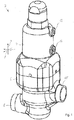
- FIG. 1 shows a schematic perspective view of a diaphragm valve 2, in which a drive housing 4 is arranged on a valve body 6.
- the valve body 6 comprises two process fluid ports 8 and 10, through which the process to be adjusted fluid can be added or removed. Furthermore, the valve body 6 comprises a not shown actuating opening for the arrangement of a membrane, with which the process fluid is provided.
- the drive housing 4 has two working fluid ports 12 and 14, by means of which a in FIG. 1 not shown drive is supplied with working fluid to put the membrane.
- FIG. 2 shows in a central schematic section along an xz plane, the drive housing 4 and the valve body 6 of the diaphragm valve 2.
- the drive housing 4 includes a mounting opening 16, which releases access to a mounting space 18, as far as the drive housing 4 is removed from the valve body 6.
- the mounting space 18 includes a biasing portion 20, wherein the biasing portion 20 merges into a drive portion 24 after a taper 22 of the inner cross section of the mounting space 18.
- the drive section 24 is connected to the working fluid ports 12 and 14.
- the valve body 6 has a valve seat 26, which to a concern of the membrane and to close the Valve seat opening 28 is used. Furthermore, a bypass channel 30 is shown, through which the process fluid can flow even when the valve seat opening 28 is closed. Of course, the valve body 6 may be formed without a bypass channel 30. Furthermore, the valve body 6 comprises the adjusting opening 32, through which the membrane is introduced into the valve body 6 during assembly of the diaphragm valve 2.
- the drive housing 4 has an external thread 36 in a feed direction 34, which can be screwed into an internal thread 38 of the valve body 6.
- the feed direction 34 points in the direction of the valve seat 26 and extends along an infeed axis which extends along the feed direction through the diaphragm valve 2.
- the external thread 36 and the internal thread 38 are preferably multi-thread, which together with stops 40 and 42 define a position of the drive housing 4 relative to the valve body 6 in a screwed state.
- the drive housing 4, an internal thread and the valve body 6 comprise a corresponding to the internal thread external thread.
- a four-start self-locking metric internal thread 38 and a four-course self-locking metric external thread 36 is used, for example with the properties M42 x Ph6 x P 1.5 (pitch 6, pitch 1.5).
- a friction angle is greater than the pitch angle.
- a trapezoidal thread can be used which has improved mobility.
- the respective threads can also be designed to be double-threaded.
- valve body 6 threaded bores and the drive housing 4 through holes.
- respective screws can be screwed through the through holes into the threaded bores of the valve body 6 to fix the drive housing 4 to the valve body 6.
- grooves 44 and 46 Parallel to the feed direction 34, grooves 44 and 46, which, as follows, extend to the internal thread 38 FIG. 5 , explained, form an anti-rotation.
- a mounting space 48 of the valve body 6 has in the feed direction 34 a clamping area 50 to a jamming of the membrane.
- FIG. 3 shows in a schematic plan view against a z-direction an embodiment of the diaphragm valve 2.
- the drive housing 4 comprises a parallel to the feed direction 34 extending through holes 52.
- the valve body 6 comprises a blind hole 54. From the in FIG. 3 shown position, the drive housing 4 is rotated by 45 ° relative to the valve body 6 according to an arrow 56, so that the mutually corresponding threads of the drive housing 4 and the valve body 6 are rotated into each other and the through holes 52 so over the blind hole 54 is to by means of a through the Through holes 52 guided and engaging in the blind hole 54 pin to set a position of the drive housing 4 to the valve body 6. In an end position, the working fluid port 12 points in the y-direction.
- FIG. 4 shows in a schematic plan view against a z-direction, an embodiment of the diaphragm valve 2.
- screws 58A to 58D guided through through holes of the valve body 4 engage in corresponding internal thread of the valve body 6 and thus define the drive body 4 to the valve body 6.
- the working fluid port 12 faces in the x direction.
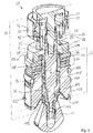
- FIG. 5 shows in a schematic perspective sectional view of an assembly 60 in a prestressed state.
- the assembly 60 includes a biasing assembly 62, a drive assembly 64, and the diaphragm 66.
- the drive assembly 64 includes a control piston 68, a spring plate 70, a first spring member 72 disposed between spring plate 70 and control piston 68, and a valve stem 74 Spiral pressure spring executed.
- the control piston 68 comprises a sealing element 76 on the circumference.
- the control piston 68 comprises an inner spring chamber 78, in which the first spring element 72 is arranged.
- the control piston 68 provides an abutment portion 80 for abutment of the first spring element 72.
- the spring plate 70 provides a contact region 82 for the first spring element 72.
- the first spring element 72 is under pressure and causes the control piston 68 and the spring plate 70 are pressed away from each other.
- the valve spindle 74 is firmly connected to the control piston 68 by means of a spindle section 84 projecting from the control piston 68.
- the spring plate 70 has a protruding and immersed in the spring chamber 78, cylindrical portion 86. Through a central passage opening 88 of the spring plate 70 is the Valve stem 74 with the spindle portion 84 passed.
- the valve spindle 74 comprises a first stop region 90 which is arranged on a side of the passage opening 88 facing away from the spring chamber 78.
- a second stop region 92 is provided by an internal cross-sectional enlargement of the portion 86 from the passage opening 88.
- the two stop portions 90 and 92 cause a limitation of movement of the spring plate 70 and the control piston 68 away from each other.
- the spring plate 70 and the control piston 68 and the spindle section 84 abut each other via the stop regions 90 and 92.
- the biasing assembly 62 is also shown in a preloaded condition and includes a pressurized second spring member 94 which is configured as a spring plate package comprising three disc springs.
- the second spring element 94 is arranged between an abutment portion 96 and a clamping portion 100.
- a cylindrical portion 102 of the clamping portion 100 protrudes through the second spring member 94 and the abutment portion 96 therethrough.
- the section 102 comprises at its distal end an annular groove arranged at its circumference into which a ring 104 is inserted.
- the ring 104 causes the abutment portion 96, which is pressed with the pressurized second spring element 94 against a feed direction 34, can be supported by means of the ring 104 on the clamping portion 100.
- the clamping portion 100 has by means of the ring 104 on a third stop area.
- the abutment portion 96 forms radially inwardly from a fourth stop area.
- By means of the third and fourth stop area is limited movement of the clamping portion 100 away from the abutment portion 96.
- the prestressed state of the biasing portion 62 is shown, in which the abutment portion 96 rests against the ring 104.
- the section 102 projects with its distal end into a receiving space 105 of the spring plate 70.
- an O-ring 106 is arranged, which consists for example of PTFE and provides a seal with a housing inner wall.
- a sliding bearing 108 is arranged, in which the valve stem 74 is guided.
- a sealing ring 110 connects to the sliding bearing 108, which is arranged in an inner groove of the clamping portion 100.
- the membrane 66 On the side facing away from the control piston 68 side of the assembly 60, the membrane 66 is arranged. In the membrane 66, a contact element 112 is screwed. In turn, the valve spindle 74 is screwed into the contact element 112. Thus, a force emanating from the control piston 68 can be transmitted to the membrane 66 by means of the contact element 112. Between the contact element 112 and the valve spindle 74, a rotation 114 is arranged, which engages by means not shown projections in longitudinal grooves of the clamping portion 100, which extend parallel to the feed direction 34 engages.
- the diaphragm 66 is made of PTFE, for example, and transitions from a central portion to a thinner, operationally movable sealing portion 116, which merges radially outwardly into a mounting portion 118.
- the fixing portion 118 is sandwiched between a clamping portion 120 of the clamping portion 100 and the clamping portion 50 of FIG Valve body 6 jammed.
- the central portion is pressed by means of the valve stem 74 for closing the valve seat opening 28 on the valve seat 26.
- a projection 122 which protrudes peripherally from the clamping portion 100, is provided for engagement in one of the grooves 44 and 46 in order to prevent or limit a rotation of the clamping portion 100 relative to the valve body 6.
- the anti-rotation 114 prevents or limits a rotation of the valve stem 74 relative to the clamping portion 100 about a Zustellachse.
- the assembly 60 ensures that all components of the assembly 60 remain substantially non-rotatable with respect to the diaphragm 66. In particular, when screwing a drive housing 4 in the valve body 6 with the introduced into the mounting space 18 assembly 60 so the friction between the mounting portion 118 and the clamping portion 50 is minimized. This helps to ensure that the membrane 66 is not damaged during assembly of the assembly 60.
- the assembly 60 can be introduced into the mounting space 18 in the prestressed state through the mounting opening 16 of the drive housing 4.
- the abutment portion 96 abuts with its surface 122 after insertion into the mounting space 18 at the taper 22.
- the drive housing 4 can be connected to the valve body 6.
- the first spring element 72 presses the spring plate 70 on the Counter bearing portion 96.
- the first spring element 72 pushes the control piston 68 against the feed direction 34 and thus also presses the valve stem 74 against the feed direction 34.
- the contact element 112 and the rotation 114 the spring force of the first spring element 72 is transmitted to the clamping portion 100.
- the clamping portion 100 in turn presses on the second spring element 94.
- the forces of the spring elements 72 and 94 and the geometric dimensions of the drive assembly 64 and the biasing assembly 62 are coordinated so that in the prestressed state of the assembly 60, the first abuts the second stop region and the third bears against the fourth stop area. In the prestressed state, all parts of the assembly 60 are captively secured together.
- FIG. 6 shows a schematic sectional view of the diaphragm valve 2, wherein the assembly 60 is disposed within the drive housing 4 and within the valve body 6.
- the control piston 68 divides the drive section 24 of the drive housing 4 into two variable volumes 124 and 126. The volumes 124 and 126 are acted upon by the working fluid ports 14 and 12 with working fluid.
- a screw 128 is rotated at the distal end of the drive housing 4 in a central internal thread of the drive housing 4 a.
- the screw 128 provides a stroke limit for the control piston 68, wherein a total stroke is adjusted by the rotation of the screw 128 in the internal thread of the drive housing 4.
- the first and second abutment areas of the drive assembly 64 are not adjacent to each other at.
- the third and fourth abutment portions of the biasing assembly 62 are not abutted.
- FIG. 7 shows the diaphragm valve 2 in a perspective schematic sectional view.
- screwing of drive housing 4 and valve body 6 is the mounting variant according to the FIG. 4 shown in which screws 58 are used to connect the drive housing 4 with the valve body 6.
- FIG. 8 shows a schematic sectional view of a section according to the embodiment of the diaphragm valve 2 after the FIG. 3 ,
- the through hole 52 of the drive housing 4 has an internal thread into which the screw 130 is turned.
- the screw 130 engages in the blind hole 54 of the valve body 6 and thus provides a safeguard against unintentional twisting off of the drive body 4.
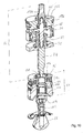
- FIG. 9 shows a further embodiment of the diaphragm valve 2 in a perspective view.
- FIG. 10 shows in a schematic exploded sectional view of the drive assembly 64, the biasing assembly 62, the anti-rotation 114, the contact member 112 and the diaphragm 66 for arrangement in the diaphragm valve 2 after the FIG. 9 , Also separated from each other, the drive assembly 64 and the biasing assembly 62 are in their respective biased states.
- the drive assembly 64 and the biasing assembly 62 are in their respective biased states.
- the drive assembly 64 of the FIG. 10 differs from the drive assembly 64 of the FIG. 5 , as opposed to the feed direction 34, a cover 132 is arranged, through which a valve spindle 74 remote from the spindle portion 134 is guided, which is fixedly connected to the control piston 68.
- a cover 132 is arranged, through which a valve spindle 74 remote from the spindle portion 134 is guided, which is fixedly connected to the control piston 68.
- another O-ring 136 seals the cover 132 against a housing inner wall of the drive housing 4.
- a sealing ring 110 seals the spindle portion 134 from the lid 132.
- FIG. 11 shows the diaphragm valve 2 in a schematic sectional view according to the embodiment of Figures 9 and 10 ,
- the drive housing 4 is closed with a cover cover 138, which is screwed into an internal thread of the drive housing 4.
- the drive housing 4 releases a first mounting opening 140 oriented away from the valve body 6.
- the drive assembly 64 can be introduced into a first mounting space section 142 via the first mounting opening 140. After the introduction of the drive assembly 64 into the first mounting space portion 142, the first mounting space portion 142 can be closed with the end cover 138.
- the mounting lid 138 sets the lid 132 relative to the drive housing 4.
- the second mounting aperture 16 exposes access to a second mounting space portion 144 in which the biasing assembly 62 is disposed.
- a passage opening 146 connects the mounting space sections 142 and 144.
- the passage opening 146 has a smaller diameter than the two mounting space sections 142 and 144. Through the passage opening 146, the valve spindle 74 is guided.
- the Through opening 146 passes through a partition wall 148, which separates the two mounting space sections 142 and 144 from each other.
- the drive assembly 64 When mounting the diaphragm valve 2 after the FIG. 11 Preferably, first, the drive assembly 64 is disposed in its preloaded state in the first mounting space portion 142. After attaching the end cover 138, the drive assembly 64 is transferred to the assembled state. In this case, the valve stem 174 already protrudes into and through the second mounting space portion 144. Subsequently, the biasing assembly 64 is guided into the second mounting space portion 144 and the valve stem 74. The anti-rotation device 114 is then inserted into the clamping section 100. Subsequently, the contact element 112 is connected to the valve spindle 74. Subsequently, the membrane 66 is connected to the contact element 112. Thus, both the drive assembly 64 and the biasing assembly 62 are disposed in the drive housing 4. The biasing assembly 62 is still in the biased state.
- the drive housing 4 is connected to the valve body 6. Characterized in that the fixing portion 118 of the diaphragm 66 between the clamping portion 100 and the clamping portion 120 and the clamping portion 50 is arranged, the biasing assembly 62 is in the arrangement of the drive housing 4 to the valve body 6 from the prestressed state in the assembled state, what means that the third and the fourth stop area do not touch in the assembled state.
- the first spring element 72 causes a return of the control piston 68 in the position shown. Therefore, the first spring element 72 can also be designated as a return spring.
- the movement of the control piston 68 is limited by the cover 132 against the feed direction 34. In the feed direction 34, the movement of the control piston 68 is limited by the spring plate 70.
- the drive assembly 64 is clamped between the partition 148 and the end cover 138.
- the abutment portion 96 is supported on the partition wall 148.
- the abutment portion 96 is thus set against the feed direction 34 relative to the drive housing 4.
- the abutment portion 96 is also fixed relative to the valve body 6 and in particular with respect to the clamping area 50.
- the second spring element 94 is thus supported on the opposite to the valve body 6 fixed abutment portion 96 and presses the clamping portion 100 in a clamping region 120 on the mounting portion 118 so as to clamp the attachment portion 118 of the diaphragm 66 fluid-tight.
- the biasing assembly 62 is clamped between the partition wall 148 and the clamping portion 50 of the valve body 6.
- the spring plate 70 is in the assembled state on the side oriented to the mounting space 142 side of the partition 148 at.
- the abutment portion 96 is located in the mounted state on the second mounting space portion 144 facing side of the partition 148 at.
- FIG. 11 is in contrast to the embodiment of the diaphragm valve 2 in the FIG. 6 the partition 148 is disposed between the drive assembly 64 and the biasing assembly 62.
- the partition wall 148 makes it possible to decouple the mounting space sections 142 and 144 in such a way that a respectively different cross section can be provided. This allows a larger version of the drive by a cross-sectional enlargement of the piston chamber in the first mounting space portion 142 compared to the cross section of the second mounting space portion 144.
Landscapes
- Engineering & Computer Science (AREA)
- General Engineering & Computer Science (AREA)
- Mechanical Engineering (AREA)
- Fluid-Driven Valves (AREA)
Abstract
Description
- Die Erfindung betrifft ein Membranventil nach dem Oberbegriff des Anspruchs 1.
- Membranventile mit einem Antriebsgehäuse und einer in dem Antriebsgehäuse angeordneten Antriebsbaugruppe zum Stellen eines Prozessfluids mittels einer Membran sind allgemein bekannt.
- Die
DE 10 2014 004 670 A1 offenbart ein Ventil mit einem Ventilgehäuse, in dem ein eine Durchströmöffnung umgebender Ventilsitz angeordnet ist. An einem Gehäuseboden eines Antriebsgehäuses ist eine Antriebsgehäuse-Schnittstelle vorgesehen. Dadurch ist es möglich, dass das Ventil einen Ventilantriebs-Baustein und einen Ventilgehäuse-Baustein besitzt, die jeweils als vormontierbare Baugruppen ausgestaltet sein können und in einfacher und schneller Weise zusammengebaut oder voneinander getrennt werden können. - Die
EP 1 953 436 A2 offenbart ein Membranventil, dessen Membran in einem Außenbereich auf einen Ventilkörper gedrückt wird. - Es ist somit Aufgabe der Erfindung, ein Membranventil nach dem Oberbegriff derart weiterzubilden, dass ein Austausch der bewegten Teile des Membranventils verbessert wird.
- Die der Erfindung zugrunde liegende Aufgabe wird durch ein Membranventil nach dem Anspruch 1 gelöst.
- Es wird vorgeschlagen, dass das Membranventil eine Vorspannbaugruppe zur Anordnung zwischen der Antriebsbaugruppe und der Membran umfasst, dass ein erstes Federelement die Antriebsbaugruppe vor Einbringung in das Antriebsgehäuse in einem vorgespannten Zustand hält, und dass ein zweites Federelement die Vorspannbaugruppe vor Einbringung in das Antriebsgehäuse in einem vorgespannten Zustand hält.
- Es wird somit auf einfache Art und Weise ein Schnellwechselsystem für ein Membranventil geschaffen, bei dem sowohl die Antriebsbaugruppe als auch die Vorspannbaugruppe in einem jeweiligen vorgespannten Zustand in das Antriebsgehäuse einbringbar sind. Vorteilhaft ermöglicht dieses Membranventil ein einfaches und schnelles Wechseln der Antriebsbaugruppe und der Vorspannbaugruppe. Es ergibt sich somit eine Zeitersparnis bei der Wartung des Membranventils, wovon Anwendungen mit einer hohen Anzahl von Schaltzyklen und kurzen Maschinenstehzeiten profitieren. Beispielhaft sei auf die Abfüllung von Getränken verwiesen.
- Eine vorteilhafte Ausführungsform des Membranventils zeichnet sich dadurch aus, dass das erste Federelement nach einem Einbringen der Antriebsbaugruppe in das Antriebsgehäuse als Rückstellfeder für einen Steuerkolben wirkt. Vorteilhaft erfüllt damit das erste Federelement mehrere Funktionen. Zum einen stellt das erste Federelement den vorgespannten Zustand her und kann nach der Montage die Funktion als Rückstellfeder für den Antrieb übernehmen.
- Eine vorteilhafte Ausführungsform des Membranventils zeichnet sich dadurch aus, dass das zweite Federelement nach dem Einbringen der Vorspannbaugruppe in das Antriebsgehäuse eine Verklemmung der Membran zwischen der Vorspannbaugruppe und einem Ventilkörper bewirkt. Somit erfüllt das zweite Federelement zwei Funktionen, was bedeutet, dass zum einen der vorgespannte Zustand der Vorspannbaugruppe vor einer Montage durch das zweite Federelement bewirkt wird. Zum anderen wird durch die Verklemmung der Membran, welche mittels der Federkraft des zweiten Federelements bewirkt wird, eine Abdichtung des Prozessfluid-führenden Bereichs gegenüber dem Antriebsbereich bewirkt.
- Eine vorteilhafte Ausführungsform des Membranventils zeichnet sich dadurch aus, dass die Antriebsbaugruppe und die Vorspannbaugruppe in ihrem jeweiligen montierten Zustand innerhalb des Antriebsgehäuses eine kleinere Längserstreckung aufweisen als in dem vorgespannten Zustand. Hierdurch wird eine Entkopplung des Vorspannzustandes von dem Montagezustand erreicht.
- Eine vorteilhafte Ausführungsform des Membranventils zeichnet sich dadurch aus, dass das Antriebsgehäuse eine Montageöffnung umfasst, welche den Zugang zu einem Montageraum des Antriebsgehäuses freigibt, wobei die Antriebsbaugruppe in dem vorgespannten Zustand und die Vorspannbaugruppe in dem vorgespannten Zustand über die Montageöffnung in den Montageraum einbringbar sind. Vorteilhaft werden die Baugruppen so über eine einzige Öffnung, die Montageöffnung, in das Antriebsgehäuse eingebracht, um anschließend das Antriebsgehäuse mit dem Ventilkörper zu verbinden. Damit wird die Anzahl der Handgriffe für einen Wechsel der Baugruppen reduziert.
- Eine vorteilhafte Ausführungsform des Membranventils zeichnet sich dadurch aus, dass ein Innenquerschnitt des Montageraums sich von der Montageöffnung weg weisend verjüngt, wobei sich die Vorspannbaugruppe in einem montierten Zustand innerhalb des Antriebsgehäuses an der Verjüngung des Innenquerschnitts abstützt. Vorteilhaft ergeben sich hierdurch geringere Kosten für die Anfertigung des Gehäuses und die Abstützung der Vorspannbaugruppe ist auf einfache Art und Weise umgesetzt.
- Eine vorteilhafte Ausführungsform des Membranventils zeichnet sich dadurch aus, dass die Antriebsbaugruppe und die Vorspannbaugruppe zu einer Einbringung in das Antriebsgehäuse verliersicher miteinander verbunden sind. Hierdurch wird ein Wechsel der Antriebsbaugruppe und der Vorspannbaugruppe weiter vereinfacht, was die Anzahl der für einen Wechsel der Baugruppen benötigten Handgriffe weiter reduziert.
- Eine vorteilhafte alternative Ausführungsform des Membranventils zeichnet sich dadurch aus, dass das Antriebsgehäuse eine von dem Ventilkörper weg orientierte erste Montageöffnung umfasst, welche den Zugang zu einem ersten Montageraumabschnitt des Antriebsgehäuses freigibt, wobei das Antriebsgehäuse eine zu dem Ventilkörper hin orientierte zweite Montageöffnung umfasst, welche den Zugang zu einem zweiten Montageraumabschnitt des Antriebsgehäuses freigibt, wobei die Antriebsbaugruppe in dem vorgespannten Zustand über die erste Montageöffnung in den ersten Montageraumabschnitt einbringbar ist, wobei die Vorspannbaugruppe in dem vorgespannten Zustand über die zweite Montageöffnung in den zweiten Montageraumabschnitt einbringbar ist, und wobei der erste und zweite Montageraumabschnitt mittels einer Durchgangsöffnung verbunden sind, durch welche eine Ventilspindel hindurchgeführt ist. Vorteilhaft können auf diese Art und Weise die Baugruppen separat voneinander gewechselt werden. Des Weiteren ergibt sich eine Entkopplung des Antriebs von der Vorspannbaugruppe. Insbesondere kann ein Antrieb stärker ausgelegt werden, da beispielsweise ein Antriebszylinderquerschnitt gegenüber dem Querschnitt des zweiten Montageraumabschnitts vergrößert ausgebildet sein kann.
- Eine vorteilhafte Ausführungsform des Membranventils zeichnet sich dadurch aus, dass die mit einem Steuerkolben der Antriebsbaugruppe verbundene Ventilspindel durch die Vorspannbaugruppe geführt mit der Membran verbunden ist, wobei die Vorspannbaugruppe ein Gleitlager umfasst, in dem die Ventilspindel geführt ist. Durch das Gleitlager wird eine zentral angeordnete Führung der Ventilspindel geschaffen, welche die Führung der Ventilspindel bei einem Schaltspiel verbessert.
- Eine vorteilhafte Ausführungsform des Membranventils zeichnet sich dadurch aus, dass die Vorspannbaugruppe und der Ventilkörper derart ineinandergreifen, dass eine Verdrehung der Vorspannbaugruppe gegenüber dem Ventilkörper um eine Zustellachse verhindert wird. Damit werden die Drehkräfte, welche auf die Membran wirken, reduziert, was die Lebensdauer der Membran erhöht.
- Eine vorteilhafte Ausführungsform des Membranventils zeichnet sich dadurch aus, dass das Antriebgehäuse ein dem Ventilkörper zugewandtes erstes Gewinde umfasst, wobei der Ventilkörper ein zu dem ersten Gewinde korrespondierendes zweites Gewinde umfasst. Durch so ineinandergreifende Gewinde kann die Verbindung zwischen Antriebsgehäuse und Ventilkörper auf einfache Art und Weise durch ein Eindrehen erfolgen. Die Anzahl der Handgriffe zur Montage des Membranventils werden reduziert.
- Eine vorteilhafte Weiterbildung zeichnet sich dadurch aus, dass das erste Gewinde und/oder das zweite Gewinde zwei- oder viergängig ausgebildet sind. Durch die mehrgängige Ausführung der Gewinde kann insbesondere eine Position von seitlich angeordneten Steuerfluid-Anschlüssen festgelegt werden. Im Falle eines viergängigen Gewindes wird so eine Positionierung der Steuerluft-Anschlüsse in 90°-Schritten erreicht. Bei einem zweigängigen Gewinde hingegen ergeben sich 180°-Schritte.
- Eine vorteilhafte Ausführungsform des Membranventils zeichnet sich dadurch aus, dass die Antriebsbaugruppe den Steuerkolben und die mit dem Steuerkolben fest verbundene Ventilspindel umfasst, wobei sich der Steuerkolben mittels des unter Druck stehenden ersten Federelements an einem Federteller abstützt, wobei die Ventilspindel durch eine Durchgangsöffnung des Federtellers hindurchgeführt ist, wobei die Ventilspindel auf einer dem Steuerkolben abgewandten Seite der Durchgangsöffnung einen ersten Anschlagbereich umfasst, und wobei in dem vorgespannten Zustand der Antriebsbaugruppe ein zweiter Anschlagbereich des Federtellers in Zusammenwirken mit dem ersten Anschlagbereich der Ventilspindel eine Bewegung des Steuerkolbens weg von dem Ventilteller begrenzt. Vorteilhaft wird durch die Anschlagbereiche eine verlierersichere Anordnung der Elemente der Antriebsbaugruppe bereitgestellt.
- Eine vorteilhafte Ausführungsform des Membranventils zeichnet sich dadurch aus, dass die vorgespannte Vorspannbaugruppe einen Gegenlagerabschnitt und einen Klemmabschnitt mit einem Klemmbereich zur Verklemmung der Membran umfasst, wobei sich der Klemmabschnitt mittels des unter Druck stehenden zweiten Federelements an dem Gegenlagerabschnitt abstützt, wobei der Klemmabschnitt abschnittsweise durch eine Durchgangsöffnung des Gegenlagerabschnitts hindurchgeführt ist, wobei der Klemmabschnitt auf einer dem Klemmbereich abgewandten Seite einen dritten Anschlagbereich umfasst, und wobei in dem vorgespannten Zustand der Vorspannbaugruppe ein vierter Anschlagbereich des Gegenlagerabschnitts in Zusammenwirken mit dem dritten Anschlagbereich des Klemmabschnitts eine Bewegung des Klemmabschnitts weg von dem Gegenlagerabschnitt begrenzt. Vorteilhaft wird durch die Anschlagbereiche eine verlierersichere Anordnung der Elemente der Vorspannbaugruppe bereitgestellt.
- Weitere Merkmale, Anwendungsmöglichkeiten und Vorteile der Erfindung ergeben sich aus der nachfolgenden Beschreibung von Ausführungsbeispielen der Erfindung, die in den Figuren der Zeichnung dargestellt sind. Für funktionsäquivalente Größen und Merkmale werden in allen Figuren auch bei unterschiedlichen Ausführungsformen die gleichen Bezugszeichen verwendet. In der Zeichnung zeigen:
-
Figur 1 in schematischer perspektivischer Ansicht ein Membranventil; -
Figur 2 in einem zentralen schematischen Schnitt ein Antriebsgehäuse und einen Ventilkörper des Membranventils; -
Figur 3 in einer schematischen Draufsicht eine Ausführungsform des Membranventils; -
Figur 4 in einer schematischen Draufsicht eine Ausführungsform des Membranventils; -
Figur 5 in einer schematischen perspektivischen Schnittansicht eine Baugruppe; -
Figur 6 eine schematische Schnittansicht des Membranventils; -
Figur 7 das Membranventil in einer perspektivischen schematischen Schnittansicht; -
Figur 8 eine schematische Schnittansicht eines Ausschnitts gemäß der Ausführungsform des Membranventils nach derFigur 3 ; -
Figur 9 eine weitere Ausführungsform des Membranventils in einer perspektivischen Ansicht; -
Figur 10 in einer schematischen Explosions-Schnittansicht die Antriebsbaugruppe und die Vorspannbaugruppe; und -
Figur 11 das Membranventil in einer schematischen Schnittansicht gemäß der Ausführungsform derFiguren 9 und10 . -
Figur 1 zeigt in schematischer perspektivischer Ansicht ein Membranventil 2, bei welchem ein Antriebsgehäuse 4 an einem Ventilkörper 6 angeordnet ist. Der Ventilkörper 6 umfasst zwei Prozessfluid-Anschlüsse 8 und 10, durch welche das zu stellende Prozess Fluid zu- bzw. abgeführt werden kann. Des Weiteren umfasst der Ventilkörper 6 eine nicht gezeigte Stellöffnung zur Anordnung einer Membran, mit welcher das Prozessfluid gestellt wird. Das Antriebsgehäuse 4 weist zwei Arbeitsfluid-Anschlüsse 12 und 14 auf, mittels denen ein inFigur 1 nicht gezeigter Antrieb mit Arbeitsfluid versorgt wird, um die Membran zu stellen. -
Figur 2 zeigt in einem zentralen schematischen Schnitt entlang einer xz-Ebene das Antriebsgehäuse 4 und den Ventilkörper 6 des Membranventils 2. Das Antriebsgehäuse 4 umfasst eine Montageöffnung 16, welche den Zugang zu einem Montageraum 18 freigibt, soweit das Antriebsgehäuse 4 von dem Ventilkörper 6 entfernt ist. Der Montageraum 18 umfasst einen Vorspannabschnitt 20, wobei der Vorspannabschnitt 20 nach einer Verjüngung 22 des Innenquerschnitts des Montageraums 18 in einen Antriebsabschnitt 24 übergeht. Der Antriebsabschnitt 24 ist mit den Arbeitsfluid-Anschlüssen 12 und 14 verbunden. - Der Ventilkörper 6 weist einen Ventilsitz 26 auf, welcher zu einem Anliegen der Membran und zum Verschließen der Ventilsitzöffnung 28 dient. Des Weiteren ist ein Bypass-Kanal 30 gezeigt, durch welchen das Prozessfluid auch bei geschlossener Ventilsitzöffnung 28 fließen kann. Selbstverständlich kann der Ventilkörper 6 auch ohne Bypass-Kanal 30 ausgebildet sein. Des Weiteren umfasst der Ventilkörper 6 die Stellöffnung 32, durch welche die Membran bei einer Montage des Membranventils 2 in den Ventilkörper 6 eingebracht wird.
- Das Antriebsgehäuse 4 weist in eine Zustellrichtung 34 ein Außengewinde 36 auf, welches in ein Innengewinde 38 des Ventilkörpers 6 eindrehbar ist. Die Zustellrichtung 34 zeigt in Richtung des Ventilsitzes 26 und verläuft entlang einer Zustellachse, welche sich längs der Zustellrichtung durch das Membranventil 2 erstreckt. Das Außengewinde 36 und das Innengewinde 38 sind bevorzugt mehrgängige Gewinde, welche gemeinsam mit Anschlägen 40 und 42 eine Position des Antriebsgehäuses 4 gegenüber dem Ventilkörper 6 in einem verschraubten Zustand festlegen. Selbstverständlich können auch das Antriebsgehäuse 4 ein Innengewinde und der Ventilkörper 6 ein zu dem Innengewinde korrespondierendes Außengewinde umfassen.
- Bevorzugt kommt, wie in
Figur 2 gezeigt, ein viergängiges selbsthemmendes metrisches Innengewinde 38 und ein viergängiges selbsthemmendes metrisches Außengewinde 36 zur Anwendung, beispielsweise mit den Eigenschaften M42 x Ph6 x P 1,5 (Steigung 6, Teilung 1,5). Bei einem selbsthemmenden Gewinde ist ein Reibwinkel größer als der Steigungswinkel. Selbstverständlich kann auch ein Trapezgewinde verwendet werden, welches eine verbesserte Beweglichkeit aufweist. Alternativ zu den viergängigen Ausführungsformen des Außengewinde 36 und des Innengewinde 38 können die jeweiligen Gewinde auch zweigängig ausgestaltet sein. - Alternativ ist auch möglich, eine eingängige Ausführung für das Außengewinde 36 und das Innengewinde 38 vorzusehen.
- Alternativ oder zusätzlich zu dem Innengewinde 38 und dem Außengewinde 36 kann der Ventilkörper 6 Gewindebohrungen und das Antriebsgehäuse 4 Durchgangsbohrungen aufweisen. Mittels der Gewindebohrungen und der Durchgangsbohrungen können jeweilige Schrauben durch die Durchgangsbohrungen geführt in die Gewindebohrungen des Ventilkörpers 6 eingedreht werden, um das Antriebsgehäuse 4 zu dem Ventilkörper 6 festzulegen.
- Parallel zur Zustellrichtung 34 erstrecken sich anschließend an das Innengewinde 38 Nuten 44 und 46, die, wie nachfolgend zu
Figur 5 , erläutert, eine Verdrehsicherung bilden. Ein Montageraum 48 des Ventilkörpers 6 weist in Zustellrichtung 34 einen Klemmbereich 50 zu einer Verklemmung der Membran auf. -
Figur 3 zeigt in einer schematischen Draufsicht entgegen einer z-Richtung eine Ausführungsform des Membranventils 2. Das Antriebsgehäuse 4 umfasst eine parallel zur Zustellrichtung 34 verlaufende Durchgangsbohrungen 52. Der Ventilkörper 6 umfasst eine Sacklochbohrung 54. Aus der inFigur 3 gezeigten Position wird das Antriebsgehäuse 4 gemäß einem Pfeil 56 um 45° gegenüber dem Ventilkörper 6 verdreht, sodass die zueinander korrespondierenden Gewinde des Antriebsgehäuses 4 und des Ventilkörper 6 ineinander gedreht werden und die Durchgangsbohrungen 52 so über der Sacklochbohrung 54 liegt, um mittels eines durch die Durchgangsbohrungen 52 geführten und in die Sacklochbohrung 54 eingreifenden Bolzen eine Position des Antriebsgehäuses 4 zu dem Ventilkörper 6 festzulegen. In einer Endposition zeigt der Arbeitsfluid-Anschluss 12 in die y-Richtung. -
Figur 4 zeigt in einer schematischen Draufsicht entgegen einer z-Richtung eine Ausführungsform des Membranventils 2. Im Gegensatz zuFigur 3 ist inFigur 4 gezeigt, dass Schrauben 58A bis 58D durch Durchgangsbohrungen des Ventilkörpers 4 geführt in entsprechende Innengewinde des Ventilkörpers 6 eingreifen und damit den Antriebskörper 4 zu dem Ventilkörper 6 festlegen. Der Arbeitsfluid-Anschluss 12 zeigt in die x-Richtung. -
Figur 5 zeigt in einer schematischen perspektivischen Schnittansicht eine Baugruppe 60 in einem vorgespannten Zustand. Die Baugruppe 60 umfasst eine Vorspannbaugruppe 62, eine Antriebsbaugruppe 64 und die Membran 66. Die Antriebsbaugruppe 64 umfasst einen Steuerkolben 68, einen Federteller 70, ein zwischen Federteller 70 und Steuerkolben 68 angeordnetes erstes Federelement 72 und eine Ventilspindel 74. Das erste Federelement 72 ist als Spiraldruckfeder ausgeführt. Der Steuerkolben 68 umfasst umfangsseitig ein Dichtelement 76. Der Steuerkolben 68 umfasst einen inneren Federraum 78, in dem das erste Federelement 72 angeordnet ist. Des Weiteren stellt der Steuerkolben 68 einen Anlageabschnitt 80 zur Anlage des ersten Federelements 72 bereit. Ebenso stellt der Federteller 70 einen Anlagebereich 82 für das erste Federelement 72 bereit. Das erste Federelement 72 steht unter Druck und bewirkt, dass der Steuerkolben 68 und der Federteller 70 voneinander weg gedrückt werden. - Die Ventilspindel 74 ist mittels eines von dem Steuerkolben 68 abragenden Spindelabschnitts 84 fest mit dem Steuerkolben 68 verbunden. Der Federteller 70 weist einen abragenden und in den Federraum 78 eintauchenden, zylindrischen Abschnitt 86 auf. Durch eine zentrale Durchgangsöffnung 88 des Federtellers 70 ist die Ventilspindel 74 mit dem Spindelabschnitt 84 hindurchgeführt. Die Ventilspindel 74 umfasst einen ersten Anschlagbereich 90, welcher auf einer dem Federraum 78 abgewandten Seite der Durchgangsöffnung 88 angeordnet ist. Ein zweiter Anschlagbereich 92 wird durch eine Innenquerschnittvergrößerung des Abschnitts 86 ausgehend von der Durchgangsöffnung 88 bereitgestellt. In dem gezeigten vorgespannten Zustand der Antriebsbaugruppe 64 bewirken die beiden Anschlagbereiche 90 und 92 eine Begrenzung einer Bewegung des Federtellers 70 und des Steuerkolbens 68 voneinander weg. In dem vorgespannten Zustand liegen der Federteller 70 und der Steuerkolben 68 bzw. der Spindelabschnitt 84 über die Anschlagbereiche 90 und 92 aneinander an.
- Die Vorspannbaugruppe 62 ist ebenfalls in einem vorgespannten Zustand gezeigt und umfasst ein unter druckstehendes zweites Federelement 94, welches als Federtellerpaket umfassend drei Tellerfedern ausgeführt ist. Das zweite Federelement 94 ist zwischen einem Gegenlagerabschnitt 96 und einem Klemmabschnitt 100 angeordnet. Ein zylindrischer Abschnitt 102 des Klemmabschnitts 100 ragt durch das zweite Federelement 94 und den Gegenlagerabschnitt 96 hindurch. Der Abschnitt 102 umfasst an seinem distalen Ende eine an seinem Umfang angeordnete Ringnut, in welche ein Ring 104 eingebracht ist. Der Ring 104 bewirkt, dass der Gegenlagerabschnitt 96, welcher mit dem unter Druck stehenden zweiten Federelement 94 entgegen einer Zustellrichtung 34 gedrückt wird, sich mittels des Ringes 104 an dem Klemmabschnitt 100 abstützen kann. Der Klemmabschnitt 100 weist mittels des Ringes 104 einen dritten Anschlagbereich auf. Der Gegenlagerabschnitt 96 bildet radial nach innen einen vierten Anschlagbereich aus. Mittels des dritten und vierten Anschlagbereichs wird eine Bewegung des Klemmabschnitts 100 weg von dem Gegenlagerabschnitt 96 begrenzt. Vorliegend ist der vorgespannte Zustand des Vorspannabschnitts 62 gezeigt, bei dem der Gegenlagerabschnitt 96 an dem Ring 104 anliegt. Der Abschnitt 102 ragt mit seinem distalen Ende in einen Aufnahmeraum 105 des Federtellers 70 hinein.
- In einer umfänglichen Nut des Klemmabschnitts 100 ist ein O-Ring 106 angeordnet, welcher beispielsweise aus PTFE besteht und eine Abdichtung mit einer Gehäuseinnenwand bereitstellt. Innerhalb des Abschnitts 102 ist ein Gleitlager 108 angeordnet, in welchem die Ventilspindel 74 geführt ist. In Zustellrichtung 34 schließt sich an das Gleitlager 108 ein Dichtring 110 an, welcher in einer Innennut des Klemmabschnitts 100 angeordnet ist.
- Auf der dem Steuerkolben 68 abgewandten Seite der Baugruppe 60 ist die Membran 66 angeordnet. In die Membran 66 ist ein Kontaktelement 112 eingedreht. In das Kontaktelement 112 ist wiederum die Ventilspindel 74 eingedreht. Somit kann eine von dem Steuerkolben 68 ausgehende Kraft mittels des Kontaktelements 112 auf die Membran 66 übertragen werden. Zwischen dem Kontaktelement 112 und der Ventilspindel 74 ist eine Verdrehsicherung 114 angeordnet, welche mittels nicht gezeigter Vorsprünge in Längsnuten des Klemmabschnitts 100, welche sich parallel zur Zustellrichtung 34 erstrecken, eingreift.
- Die Membran 66 besteht beispielsweise aus PTFE und geht von einem zentralen Abschnitt in einen dünner ausgestalteten im Betrieb beweglichen Dichtabschnitt 116 über, welcher radial nach außen in einen Befestigungsabschnitt 118 übergeht. Der Befestigungsabschnitt 118 wird zwischen einem Klemmbereich 120 des Klemmabschnitts 100 und dem Klemmbereich 50 des Ventilkörpers 6 verklemmt. Der zentrale Abschnitt wird mittels der Ventilspindel 74 zum Verschließen der Ventilsitzöffnung 28 auf den Ventilsitz 26 gedrückt.
- Ein Vorsprung 122, welcher umfangsseitig von dem Klemmabschnitt 100 abragt, ist zu einem Eingriff in eine der Nuten 44 und 46 vorgesehen, um eine Verdrehung des Klemmabschnitts 100 gegenüber dem Ventilkörper 6 zu verhindern bzw. zu begrenzen. Somit besteht eine Verdrehsicherung zwischen dem Ventilkörper 6 und dem Klemmabschnitt 100. Die Verdrehsicherung 114 verhindert bzw. begrenzt eine Verdrehung der Ventilspindel 74 gegenüber dem Klemmabschnitt 100 um eine Zustellachse. Somit stellt die Baugruppe 60 sicher, dass alle Bauteile der Baugruppe 60 gegenüber der Membran 66 im Wesentlichen verdrehsicher angeordnet bleiben. Insbesondere bei einem Eindrehen eines Antriebsgehäuses 4 in den Ventilkörper 6 mit der in dem Montageraum 18 eingebrachten Baugruppe 60 wird so die Reibung zwischen dem Befestigungsabschnitt 118 und dem Klemmbereich 50 minimiert. Dies trägt dazu bei, dass die Membran 66 bei der Montage der Baugruppe 60 nicht beschädigt wird.
- Die Baugruppe 60 kann in dem vorgespannten Zustand durch die Montageöffnung 16 des Antriebsgehäuses 4 in den Montageraum 18 eingebracht werden. Der Gegenlagerabschnitt 96 liegt mit seiner Oberfläche 122 nach dem Einbringen in den Montageraum 18 an der Verjüngung 22 an. Nachdem die Baugruppe 60 in den Montageraum 18 eingebracht ist, kann das Antriebsgehäuse 4 mit dem Ventilkörper 6 verbunden werden.
- In dem gezeigten vorgespannten Zustand der Baugruppe 60 drückt das erste Federelement 72 den Federteller 70 auf den Gegenlagerabschnitt 96. Das erste Federelement 72 drückt den Steuerkolben 68 entgegen der Zustellrichtung 34 und drückt damit ebenso die Ventilspindel 74 entgegen der Zustellrichtung 34. Mittels des Kontaktelements 112 und der Verdrehsicherung 114 wird die Federkraft des ersten Federelements 72 auf den Klemmabschnitt 100 übertragen. Der Klemmabschnitt 100 wiederum drückt auf das zweite Federelement 94. Die Kräfte der Federelemente 72 und 94 sowie die geometrischen Abmessungen der Antriebsbaugruppe 64 und der Vorspannbaugruppe 62 sind derart aufeinander abgestimmt, dass in dem vorgespannten Zustand der Baugruppe 60 der erste an dem zweiten Anschlagbereich anliegt und der dritte an dem vierten Anschlagbereich anliegt. In dem vorgespannten Zustand sind alle Teile der Baugruppe 60 verliersicher miteinander befestigt.
-
Figur 6 zeigt eine schematische Schnittansicht des Membranventils 2, wobei die Baugruppe 60 innerhalb des Antriebsgehäuses 4 und innerhalb des Ventilkörpers 6 angeordnet ist. Der Steuerkolben 68 unterteilt den Antriebsabschnitt 24 des Antriebsgehäuses 4 in zwei veränderliche Volumina 124 und 126. Die Volumina 124 und 126 sind über die Arbeitsfluid-Anschlüsse 14 und 12 mit Arbeitsfluid beaufschlagbar. - Eine Schraube 128 ist am distalen Ende des Antriebsgehäuses 4 in ein zentrales Innengewinde des Antriebsgehäuses 4 ein gedreht. Die Schraube 128 stellt eine Hubbegrenzung für den Steuerkolben 68 bereit, wobei ein Gesamthub durch die Eindrehung der Schraube 128 in das Innengewinde des Antriebsgehäuses 4 eingestellt wird.
- In dem montierten Zustand liegen der erste und der zweite Anschlagbereich der Antriebsbaugruppe 64 nicht aneinander an. In dem montierten Zustand liegen der dritte und der vierte Anschlagbereich der Vorspannbaugruppe 62 nicht aneinander an.
-
Figur 7 zeigt das Membranventil 2 in einer perspektivischen schematischen Schnittansicht. Alternativ zu der inFigur 6 gezeigten Verschraubung von Antriebsgehäuse 4 und Ventilkörper 6 ist die Befestigungsvariante gemäß derFigur 4 gezeigt, bei welcher Schrauben 58 zur Verbindung des Antriebsgehäuses 4 mit dem Ventilkörper 6 dienen. -
Figur 8 zeigt eine schematische Schnittansicht eines Ausschnitts gemäß der Ausführungsform des Membranventils 2 nach derFigur 3 . Die Durchgangsbohrung 52 des Antriebsgehäuses 4 weist ein Innengewinde auf, in welche die Schraube 130 ein gedreht ist. Die Schraube 130 greift in das Sackloch 54 des Ventilkörpers 6 ein und bietet damit eine Sicherung gegen unbeabsichtigtes Abdrehen des Antriebskörpers 4. -
Figur 9 zeigt eine weitere Ausführungsform des Membranventils 2 in einer perspektivischen Ansicht. -
Figur 10 zeigt in einer schematischen Explosions-Schnittansicht die Antriebsbaugruppe 64, die Vorspannbaugruppe 62, die Verdrehsicherung 114, das Kontaktelement 112 und die Membran 66 zu Anordnung in dem Membranventil 2 nach derFigur 9 . Auch separiert voneinander befinden sich die Antriebsbaugruppe 64 und die Vorspannbaugruppe 62 in ihrem jeweiligen vorgespannten Zustand. Zum grundsätzlichen Aufbau der Antriebsbaugruppe 64 und der Vorspannbaugruppe 62 wird auf die Beschreibung zuFigur 5 verwiesen. - Die Antriebsbaugruppe 64 der
Figur 10 unterscheidet sich dahingehend von der Antriebsbaugruppe 64 derFigur 5 , als das entgegen der Zustellrichtung 34 ein Deckel 132 angeordnet ist, durch welcher ein der Ventilspindel 74 abgewandter Spindelabschnitt 134 geführt ist, welcher fest mit dem Steuerkolben 68 verbunden ist. Nach außen dichtet ein weiterer O-Ring 136 den Deckel 132 gegenüber einer Gehäuseinnenwand des Antriebsgehäuses 4 ab. Nach innen dichtet ein Dichtring 110 den Spindelabschnitt 134 gegenüber dem Deckel 132 ab. -
Figur 11 zeigt das Membranventil 2 in einer schematischen Schnittansicht gemäß der Ausführungsform derFiguren 9 und10 . Das Antriebsgehäuse 4 ist mit einem Abschlussdeckel 138, welcher in ein Innengewinde des Antriebsgehäuses 4 eingedreht ist, verschlossen. Bei abgenommenem Abschlussdeckel 138 gibt das Antriebsgehäuse 4 eine von dem Ventilkörper 6 weg orientierte erste Montageöffnung 140 frei. Über die erste Montageöffnung 140 ist die Antriebsbaugruppe 64 in einen ersten Montageraumabschnitt 142 einbringbar. Nach dem Einbringen der Antriebsbaugruppe 64 in den ersten Montageraumabschnitt 142 kann der erste Montageraumabschnitt 142 mit dem Abschlussdeckel 138 verschlossen werden. Der Montagedeckel 138 legt den Deckel 132 gegenüber dem Antriebsgehäuse 4 fest. - Die zweite Montageöffnung 16 gibt den Zugang auf einen zweiten Montageraumabschnitt 144 frei, in welchem die Vorspannbaugruppe 62 angeordnet wird. Eine Durchgangsöffnung 146 verbindet die Montageraumabschnitte 142 und 144. Die Durchgangsöffnung 146 weist einen geringeren Durchmesser auf als die beiden Montageraumabschnitte 142 und 144. Durch die Durchgangsöffnung 146 ist die Ventilspindel 74 geführt. Die Durchgangsöffnung 146 führt durch eine Trennwand 148, welche die beiden Montageraumabschnitte 142 und 144 voneinander trennt.
- Bei einer Montage des Membranventils 2 nach der
Figur 11 wird bevorzugt zunächst die Antriebsbaugruppe 64 in ihrem vorgespannten Zustand in dem ersten Montageraumabschnitt 142 angeordnet. Nach der Anbringung des Abschlussdeckels 138 ist die Antriebsbaugruppe 64 in den montierten Zustand überführt. Hierbei ragt die Ventilspindel 174 bereits in den und durch den zweiten Montageraumabschnitt 144. Anschließend wird die Vorspannbaugruppe 64 in den zweiten Montageraumabschnitt 144 und über die Ventilspindel 74 geführt. Die Verdrehsicherung 114 wird anschließend in den Klemmabschnitt 100 eingeführt. Anschließend wird das Kontaktelement 112 mit der Ventilspindel 74 verbunden. Anschließend wird die Membran 66 mit dem Kontaktelement 112 verbunden. Damit sind sowohl die Antriebsbaugruppe 64 als auch die Vorspannbaugruppe 62 in dem Antriebsgehäuse 4 angeordnet. Die Vorspannbaugruppe 62 befindet sich noch in dem vorgespannten Zustand. - Nach der Anordnung der Antriebsbaugruppe 64 und der Vorspannbaugruppe 62 in dem Antriebsgehäuse 4 wird das Antriebsgehäuse 4 mit dem Ventilkörper 6 verbunden. Dadurch, dass der Befestigungsabschnitt 118 der Membran 66 zwischen dem Klemmabschnitt 100 bzw. dem Klemmbereich 120 und dem Klemmbereich 50 angeordnet ist, geht die Vorspannbaugruppe 62 bei der Anordnung des Antriebsgehäuses 4 an den Ventilkörper 6 von dem vorgespannten Zustand in den montierten Zustand über, was bedeutet, dass sich der dritte und der vierte Anschlagbereich im montierten Zustand nicht berühren.
- In dem montierten Zustand des Membranventils 2 in
Figur 11 bildet ein Teil des ersten Montageraums 142 einen Hubzylinder für den Steuerkolben 68. In dem montierten Zustand des Membranventils 2 bewirkt das erste Federelement 72 eine Rückstellung des Steuerkolbens 68 in die gezeigte Position. Deshalb ist das erste Federelement 72 auch als Rückstellfeder bezeichenbar. Die Bewegung des Steuerkolbens 68 wird entgegen der Zustellrichtung 34 von den Deckel 132 begrenzt. In Zustellrichtung 34 wird die Bewegung des Steuerkolbens 68 von dem Federteller 70 begrenzt. Die Antriebsbaugruppe 64 wird zwischen der Trennwand 148 und dem Abschlussdeckel 138 verklemmt. - In dem montierten Zustand stützt sich der Gegenlagerabschnitt 96 an der Trennwand 148 ab. Der Gegenlagerabschnitt 96 ist damit entgegen der Zustellrichtung 34 gegenüber dem Antriebsgehäuse 4 festgelegt. Durch die Festlegung des Antriebsgehäuses 4 zu dem Ventilkörper 6 wird der Gegenlagerabschnitt 96 auch gegenüber dem Ventilkörper 6 und insbesondere gegenüber dem Klemmbereich 50 festgelegt. Das zweite Federelement 94 stützt sich damit an dem gegenüber dem Ventilkörper 6 festgelegten Gegenlagerabschnitt 96 ab und drückt den Klemmabschnitt 100 in einem Klemmbereich 120 auf den Befestigungsabschnitt 118, um damit den Befestigungsabschnitt 118 der Membran 66 fluiddicht zu verklemmen. In dem montierten Zustand ist die Vorspannbaugruppe 62 zwischen der Trennwand 148 und dem Klemmbereich 50 des Ventilkörpers 6 verklemmt.
- Der Federteller 70 liegt im montierten Zustand an der zu dem Montageraumabschnitt 142 orientierten Seite der Trennwand 148 an. Der Gegenlagerabschnitt 96 liegt in dem montierten Zustand an der dem zweiten Montageraumabschnitt 144 zugewandten Seite der Trennwand 148 an.
- In
Figur 11 ist im Unterschied zu der Ausführungsform des Membranventils 2 in derFigur 6 die Trennwand 148 zwischen der Antriebsbaugruppe 64 und der Vorspannbaugruppe 62 angeordnet. Die Trennwand 148 ermöglicht eine Entkopplung der Montageraumabschnitte 142 und 144 dahingehend, dass ein jeweils unterschiedlicher Querschnitt vorgesehen sein kann. Dies ermöglicht durch eine Querschnittsvergrößerung des Kolbenraums in dem ersten Montageraumabschnitt 142 im Vergleich zu dem Querschnitt des zweiten Montageraumabschnitts 144 eine stärkere Ausführung des Antriebs.
Claims (14)
- Ein Membranventil (2) mit einem Antriebsgehäuse (4) und einer in dem Antriebsgehäuse (4) angeordneten Antriebsbaugruppe (64) zum Stellen eines Prozessfluids mittels einer Membran (66),
dadurch gekennzeichnet,- dass das Membranventil (2) eine Vorspannbaugruppe (62) zur Anordnung zwischen der Antriebsbaugruppe (64) und der Membran (66) umfasst,- dass ein erstes Federelement (72) die Antriebsbaugruppe (64) vor Einbringung in das Antriebsgehäuse (4) in einem vorgespannten Zustand hält, und- dass ein zweites Federelement (94) die Vorspannbaugruppe (62) vor Einbringung in das Antriebsgehäuse (4) in einem vorgespannten Zustand hält. - Das Membranventil (2) nach Anspruch 1,- wobei das erste Federelement (72) nach einem Einbringen der Antriebsbaugruppe (64) in das Antriebsgehäuse (4) als Rückstellfeder für einen Antrieb, insbesondere einen Steuerkolben (68), wirkt.
- Das Membranventil (2) nach Anspruch 1 oder 2,- wobei das zweite Federelement (94) nach dem Einbringen der Vorspannbaugruppe (62) in das Antriebsgehäuse (4) eine Verklemmung der Membran (66) zwischen der Vorspannbaugruppe (64) und einem Ventilkörper (6) bewirkt.
- Das Membranventil (2) nach einem der vorstehenden Ansprüche,- wobei die Antriebsbaugruppe (64) und die Vorspannbaugruppe (62) in ihrem jeweiligen montierten Zustand innerhalb des Antriebsgehäuses (4) eine kleinere Längserstreckung aufweisen als in dem vorgespannten Zustand.
- Das Membranventil (2) nach einem der vorstehenden Ansprüche,- wobei das Antriebsgehäuse (4) eine Montageöffnung (16) umfasst, welche den Zugang zu einem Montageraum (18) des Antriebsgehäuses (4) freigibt,- wobei die Antriebsbaugruppe (64) in dem vorgespannten Zustand und die Vorspannbaugruppe (62) in dem vorgespannten Zustand über die Montageöffnung (16) in den Montageraum (18) einbringbar sind.
- Das Membranventil (2) nach dem Anspruch 5,- wobei ein Innenquerschnitt des Montageraums (16) sich von der Montageöffnung (16) weg weisend verjüngt, und- wobei sich die Vorspannbaugruppe (62) in einem montierten Zustand innerhalb des Antriebsgehäuses (4) an der Verjüngung (22) des Innenquerschnitts abstützt.
- Das Membranventil (2) nach Anspruch 5 oder 6,- wobei die Antriebsbaugruppe (64) und die Vorspannbaugruppe (62) zu einer Einbringung in das Antriebsgehäuse (4) verliersicher miteinander verbunden sind.
- Das Membranventil (2) nach einem der Ansprüche 1 bis 4,- wobei das Antriebsgehäuse (4) eine von dem Ventilkörper (6) weg orientierte erste Montageöffnung (140) umfasst, welche den Zugang zu einem ersten Montageraumabschnitt (142) des Antriebsgehäuses (4) freigibt,- wobei das Antriebsgehäuse (4) eine zu dem Ventilkörper (6) hin orientierte zweite Montageöffnung (16) umfasst, welche den Zugang zu einem zweiten Montageraumabschnitt (144) des Antriebsgehäuses (6) freigibt,- wobei die Antriebsbaugruppe (64) in dem vorgespannten Zustand über die erste Montageöffnung (140) in den ersten Montageraumabschnitt (142) einbringbar ist,- wobei die Vorspannbaugruppe (62) in dem vorgespannten Zustand über die zweite Montageöffnung (16) in den zweiten Montageraumabschnitt (142) einbringbar ist, und- wobei der erste und zweite Montageraumabschnitt (142, 144) mittels einer Durchgangsöffnung (104) verbunden sind, durch welche eine Ventilspindel (74) hindurchgeführt ist.
- Das Membranventil (2) nach einem der vorstehenden Ansprüche,- wobei die mit dem Steuerkolben (68) der Antriebsbaugruppe (64) verbundene Ventilspindel (74) durch die Vorspannbaugruppe (62) geführt mit der Membran (66) verbunden ist, und- wobei die Vorspannbaugruppe (62) ein Gleitlager (108) umfasst, in dem die Ventilspindel (74) geführt ist.
- Das Membranventil (2) nach einem der vorstehenden Ansprüche,- wobei die Vorspannbaugruppe (62) und der Ventilkörper (6) derart ineinandergreifen, dass eine Verdrehung der Vorspannbaugruppe (62) gegenüber dem Ventilkörper (6) um eine Zustellachse verhindert wird.
- Das Membranventil (2) nach einem der vorstehenden Ansprüche,- wobei das Antriebgehäuse (4) ein dem Ventilkörper (6) zugewandtes erstes Gewinde (36) umfasst, und- wobei der Ventilkörper (6) ein zu dem ersten Gewinde (36) korrespondierendes zweites Gewinde (38) umfasst.
- Das Membranventil (2) nach dem vorstehenden Anspruch,- wobei das erste Gewinde (36) und/oder das zweite Gewinde (38) zwei- oder viergängig ausgebildet ist.
- Das Membranventil (2) nach einem der vorstehenden Ansprüche,- wobei die Antriebsbaugruppe (64) den Steuerkolben (68) und die mit dem Steuerkolben (68) fest verbundene Ventilspindel (74) umfasst,- wobei sich der Steuerkolben (68) mittels des unter Druck stehenden ersten Federelements (72) an einem Federteller (70) abstützt,- wobei die Ventilspindel (74) durch eine Durchgangsöffnung (88) des Federtellers (70) hindurchgeführt ist,- wobei die Ventilspindel (74) auf einer dem Steuerkolben (68) abgewandten Seite der Durchgangsöffnung (88) einen ersten Anschlagbereich (90) umfasst, und- wobei in dem vorgespannten Zustand der Antriebsbaugruppe (64) ein zweiter Anschlagbereich (92) des Federtellers (70) in Zusammenwirken mit dem ersten Anschlagbereich (90) der Ventilspindel (74) eine Bewegung des Steuerkolbens (68) weg von dem Ventilteller (70) begrenzt.
- Ein Membranventil (2) nach einem der vorstehenden Ansprüche,- wobei die Vorspannbaugruppe (62) einen Gegenlagerabschnitt (96) und einen Klemmabschnitt (100) mit einem Klemmbereich (120) zur Verklemmung der Membran (66) umfasst,- wobei sich der Klemmabschnitt (100) mittels des unter Druck stehenden zweiten Federelements (94) an dem Gegenlagerabschnitt (96) abstützt,- wobei der Klemmabschnitt (100) abschnittsweise durch eine Durchgangsöffnung des Gegenlagerabschnitts (96) hindurchgeführt ist,- wobei der Klemmabschnitt (100) auf einer dem Klemmbereich (120) abgewandten Seite einen dritten Anschlagbereich umfasst, und- wobei in dem vorgespannten Zustand der Vorspannbaugruppe (62) ein vierter Anschlagbereich des Gegenlagerabschnitts (96) in Zusammenwirken mit dem dritten Anschlagbereich des Klemmabschnitts (100) eine Bewegung des Klemmabschnitts (100) weg von dem Gegenlagerabschnitt (96) begrenzt.
Applications Claiming Priority (1)
| Application Number | Priority Date | Filing Date | Title |
|---|---|---|---|
| DE102016115638.8A DE102016115638A1 (de) | 2016-08-23 | 2016-08-23 | Membranventil |
Publications (2)
| Publication Number | Publication Date |
|---|---|
| EP3287679A1 true EP3287679A1 (de) | 2018-02-28 |
| EP3287679B1 EP3287679B1 (de) | 2020-05-06 |
Family
ID=59506170
Family Applications (1)
| Application Number | Title | Priority Date | Filing Date |
|---|---|---|---|
| EP17184254.5A Active EP3287679B1 (de) | 2016-08-23 | 2017-08-01 | Membranventil |
Country Status (4)
| Country | Link |
|---|---|
| US (1) | US10337632B2 (de) |
| EP (1) | EP3287679B1 (de) |
| CN (1) | CN107763244B (de) |
| DE (1) | DE102016115638A1 (de) |
Cited By (3)
| Publication number | Priority date | Publication date | Assignee | Title |
|---|---|---|---|---|
| WO2019215744A1 (en) * | 2018-05-09 | 2019-11-14 | Ham-Let (Israel - Canada ) Ltd | Flow control valve assembly and complementary adjustment tool set |
| WO2020120070A1 (de) * | 2018-12-11 | 2020-06-18 | Gemü Gebr. Müller Apparatebau Gmbh & Co. Kommanditgesellschaft | Ventilantrieb |
| WO2020156901A1 (de) * | 2019-01-31 | 2020-08-06 | Gemü Gebr. Müller Apparatebau Gmbh & Co. Kommanditgesellschaft | Absperrmittel |
Families Citing this family (5)
| Publication number | Priority date | Publication date | Assignee | Title |
|---|---|---|---|---|
| WO2019164700A1 (en) * | 2018-02-22 | 2019-08-29 | Swagelok Company | Flow control device with flow adjustment mechanism |
| DE102020134305B4 (de) | 2020-12-18 | 2023-09-14 | Sed Flow Control Gmbh | Membranventil |
| DE102020134304A1 (de) * | 2020-12-18 | 2022-06-23 | Sed Flow Control Gmbh | Membranventil |
| DE102021108093A1 (de) | 2021-03-30 | 2022-10-06 | Gemü Gebr. Müller Apparatebau Gmbh & Co. Kommanditgesellschaft | Membranventil |
| DE102021120895A1 (de) * | 2021-08-11 | 2023-02-16 | Gemü Gebr. Müller Apparatebau Gmbh & Co. Kommanditgesellschaft | Ventilantrieb, Ventilanordnung und Verfahren |
Citations (4)
| Publication number | Priority date | Publication date | Assignee | Title |
|---|---|---|---|---|
| US4840347A (en) * | 1988-03-14 | 1989-06-20 | Fujikura Rubber, Ltd. | Pneumatically-operated valve |
| US6685164B1 (en) * | 2000-09-11 | 2004-02-03 | Hamai Industries Limited | Control valve and diaphragm for use in the control valve |
| US20090050832A1 (en) * | 2005-03-01 | 2009-02-26 | Fujikura Rubber Ltd. | Normally-closed valve having a microflow rate adjusting device |
| DE102014004670A1 (de) * | 2014-03-31 | 2015-10-01 | Festo Ag & Co. Kg | Ventil |
Family Cites Families (10)
| Publication number | Priority date | Publication date | Assignee | Title |
|---|---|---|---|---|
| US3978880A (en) * | 1975-06-23 | 1976-09-07 | Olin Corporation | Regulator valve diaphragm and valve assembly including the same |
| JPS61223386A (ja) * | 1985-03-29 | 1986-10-03 | Fujikura Rubber Ltd | 空気作動弁 |
| CA1276133C (en) | 1985-03-29 | 1990-11-13 | Ryozo Ariizumi | Pneumatically operated valve |
| US4712575A (en) | 1987-03-02 | 1987-12-15 | A. W. Cash Valve Manufacturing Corporation | Self-draining hose connection vacuum breaker and backflow preventer |
| US4903939A (en) * | 1988-03-14 | 1990-02-27 | Fujikura Rubber, Ltd. | Pneumatically-operated valve |
| AU2003211853A1 (en) * | 2003-03-07 | 2004-09-28 | Ckd Corporation | Flow control valve |
| SE532056C2 (sv) | 2007-02-02 | 2009-10-13 | Millipore Ab | Ventiltätning |
| JP4640551B2 (ja) * | 2007-12-04 | 2011-03-02 | Smc株式会社 | 流体圧機器の製造方法 |
| JP5986450B2 (ja) | 2012-08-06 | 2016-09-06 | サーパス工業株式会社 | 空気圧操作弁及びその組立方法 |
| DE102014013512A1 (de) | 2014-09-11 | 2016-03-17 | Festo Ag & Co. Kg | Membranventil |
-
2016
- 2016-08-23 DE DE102016115638.8A patent/DE102016115638A1/de not_active Withdrawn
-
2017
- 2017-08-01 EP EP17184254.5A patent/EP3287679B1/de active Active
- 2017-08-22 CN CN201710726522.3A patent/CN107763244B/zh active Active
- 2017-08-23 US US15/683,978 patent/US10337632B2/en active Active
Patent Citations (4)
| Publication number | Priority date | Publication date | Assignee | Title |
|---|---|---|---|---|
| US4840347A (en) * | 1988-03-14 | 1989-06-20 | Fujikura Rubber, Ltd. | Pneumatically-operated valve |
| US6685164B1 (en) * | 2000-09-11 | 2004-02-03 | Hamai Industries Limited | Control valve and diaphragm for use in the control valve |
| US20090050832A1 (en) * | 2005-03-01 | 2009-02-26 | Fujikura Rubber Ltd. | Normally-closed valve having a microflow rate adjusting device |
| DE102014004670A1 (de) * | 2014-03-31 | 2015-10-01 | Festo Ag & Co. Kg | Ventil |
Cited By (4)
| Publication number | Priority date | Publication date | Assignee | Title |
|---|---|---|---|---|
| WO2019215744A1 (en) * | 2018-05-09 | 2019-11-14 | Ham-Let (Israel - Canada ) Ltd | Flow control valve assembly and complementary adjustment tool set |
| US11331778B2 (en) | 2018-05-09 | 2022-05-17 | Ham-Let (Israel—Canada) Ltd | Flow control valve assembly and complementary adjustment tool set |
| WO2020120070A1 (de) * | 2018-12-11 | 2020-06-18 | Gemü Gebr. Müller Apparatebau Gmbh & Co. Kommanditgesellschaft | Ventilantrieb |
| WO2020156901A1 (de) * | 2019-01-31 | 2020-08-06 | Gemü Gebr. Müller Apparatebau Gmbh & Co. Kommanditgesellschaft | Absperrmittel |
Also Published As
| Publication number | Publication date |
|---|---|
| CN107763244A (zh) | 2018-03-06 |
| US20180195636A1 (en) | 2018-07-12 |
| US10337632B2 (en) | 2019-07-02 |
| EP3287679B1 (de) | 2020-05-06 |
| DE102016115638A1 (de) | 2018-03-01 |
| CN107763244B (zh) | 2020-10-27 |
Similar Documents
| Publication | Publication Date | Title |
|---|---|---|
| EP3287679B1 (de) | Membranventil | |
| EP1963627B1 (de) | Nockenwellenverstellerzuleitung | |
| DE102005030820B3 (de) | Spannvorrichtung | |
| EP3090196B1 (de) | Ventil | |
| EP1970610A1 (de) | Vorrichtung zur Regelung eines fluiden oder gasförmigen Mediums | |
| DE102004002995A1 (de) | Thermostatventilanordnung | |
| EP2354588A2 (de) | Kolben-Zylinderaggregat | |
| WO2003014570A1 (de) | Ventilblock für eine regelvorrichtung, insbesondere für eine hydrostatische maschine | |
| DE19602796B4 (de) | Steuerventil für kleinen Durchfluß | |
| DE3015830C2 (de) | ||
| DE102016105840A1 (de) | Membranventil | |
| DE102016219720A1 (de) | Druckventil | |
| EP3246605B1 (de) | Membranventil | |
| EP2690327B1 (de) | Hydraulisches Wegeventil | |
| EP3610160A1 (de) | Doppelt wirkendes überströmventil eines arbeitszylindes und master-arbeitszylinder | |
| DE4025488A1 (de) | Rueckschlagventil | |
| WO1996003586A1 (de) | Positionierantrieb, insbesondere für eine werkzeugmaschine | |
| EP1001196B1 (de) | Druckbegrenzungsventil, insbesondere für Fahrzeuge | |
| DE102009055118B4 (de) | Magnetventil sowie Fahrerassistenzeinrichtung | |
| EP2267343A1 (de) | Einschraub-Wege-Sitzventil | |
| DE102006030973B3 (de) | Systemtrenner | |
| EP3686465A1 (de) | Schnellschaltventil | |
| EP0221231A1 (de) | Schaltventil mit keramischen Ventilelementen | |
| DE19934383A1 (de) | Dämpfungseinrichtung und Ventileinsatz für eine solche Dämpfungseinrichtung | |
| EP0093783B1 (de) | Durchströmventil |
Legal Events
| Date | Code | Title | Description |
|---|---|---|---|
| PUAI | Public reference made under article 153(3) epc to a published international application that has entered the european phase |
Free format text: ORIGINAL CODE: 0009012 |
|
| STAA | Information on the status of an ep patent application or granted ep patent |
Free format text: STATUS: THE APPLICATION HAS BEEN PUBLISHED |
|
| AK | Designated contracting states |
Kind code of ref document: A1 Designated state(s): AL AT BE BG CH CY CZ DE DK EE ES FI FR GB GR HR HU IE IS IT LI LT LU LV MC MK MT NL NO PL PT RO RS SE SI SK SM TR |
|
| AX | Request for extension of the european patent |
Extension state: BA ME |
|
| STAA | Information on the status of an ep patent application or granted ep patent |
Free format text: STATUS: REQUEST FOR EXAMINATION WAS MADE |
|
| 17P | Request for examination filed |
Effective date: 20180731 |
|
| RBV | Designated contracting states (corrected) |
Designated state(s): AL AT BE BG CH CY CZ DE DK EE ES FI FR GB GR HR HU IE IS IT LI LT LU LV MC MK MT NL NO PL PT RO RS SE SI SK SM TR |
|
| STAA | Information on the status of an ep patent application or granted ep patent |
Free format text: STATUS: EXAMINATION IS IN PROGRESS |
|
| 17Q | First examination report despatched |
Effective date: 20190116 |
|
| GRAP | Despatch of communication of intention to grant a patent |
Free format text: ORIGINAL CODE: EPIDOSNIGR1 |
|
| STAA | Information on the status of an ep patent application or granted ep patent |
Free format text: STATUS: GRANT OF PATENT IS INTENDED |
|
| INTG | Intention to grant announced |
Effective date: 20191217 |
|
| GRAS | Grant fee paid |
Free format text: ORIGINAL CODE: EPIDOSNIGR3 |
|
| GRAA | (expected) grant |
Free format text: ORIGINAL CODE: 0009210 |
|
| STAA | Information on the status of an ep patent application or granted ep patent |
Free format text: STATUS: THE PATENT HAS BEEN GRANTED |
|
| AK | Designated contracting states |
Kind code of ref document: B1 Designated state(s): AL AT BE BG CH CY CZ DE DK EE ES FI FR GB GR HR HU IE IS IT LI LT LU LV MC MK MT NL NO PL PT RO RS SE SI SK SM TR |
|
| RAP1 | Party data changed (applicant data changed or rights of an application transferred) |
Owner name: GEMUE GEBR. MUELLER APPARATEBAU GMBH & CO. KOMMANDITGESELLSCHAFT |
|
| REG | Reference to a national code |
Ref country code: GB Ref legal event code: FG4D Free format text: NOT ENGLISH |
|
| REG | Reference to a national code |
Ref country code: AT Ref legal event code: REF Ref document number: 1267291 Country of ref document: AT Kind code of ref document: T Effective date: 20200515 Ref country code: CH Ref legal event code: EP |
|
| REG | Reference to a national code |
Ref country code: IE Ref legal event code: FG4D Free format text: LANGUAGE OF EP DOCUMENT: GERMAN |
|
| REG | Reference to a national code |
Ref country code: DE Ref legal event code: R096 Ref document number: 502017005119 Country of ref document: DE |
|
| REG | Reference to a national code |
Ref country code: SE Ref legal event code: TRGR |
|
| REG | Reference to a national code |
Ref country code: LT Ref legal event code: MG4D |
|
| REG | Reference to a national code |
Ref country code: NL Ref legal event code: MP Effective date: 20200506 |
|
| PG25 | Lapsed in a contracting state [announced via postgrant information from national office to epo] |
Ref country code: PT Free format text: LAPSE BECAUSE OF FAILURE TO SUBMIT A TRANSLATION OF THE DESCRIPTION OR TO PAY THE FEE WITHIN THE PRESCRIBED TIME-LIMIT Effective date: 20200907 Ref country code: GR Free format text: LAPSE BECAUSE OF FAILURE TO SUBMIT A TRANSLATION OF THE DESCRIPTION OR TO PAY THE FEE WITHIN THE PRESCRIBED TIME-LIMIT Effective date: 20200807 Ref country code: IS Free format text: LAPSE BECAUSE OF FAILURE TO SUBMIT A TRANSLATION OF THE DESCRIPTION OR TO PAY THE FEE WITHIN THE PRESCRIBED TIME-LIMIT Effective date: 20200906 Ref country code: FI Free format text: LAPSE BECAUSE OF FAILURE TO SUBMIT A TRANSLATION OF THE DESCRIPTION OR TO PAY THE FEE WITHIN THE PRESCRIBED TIME-LIMIT Effective date: 20200506 Ref country code: NO Free format text: LAPSE BECAUSE OF FAILURE TO SUBMIT A TRANSLATION OF THE DESCRIPTION OR TO PAY THE FEE WITHIN THE PRESCRIBED TIME-LIMIT Effective date: 20200806 Ref country code: LT Free format text: LAPSE BECAUSE OF FAILURE TO SUBMIT A TRANSLATION OF THE DESCRIPTION OR TO PAY THE FEE WITHIN THE PRESCRIBED TIME-LIMIT Effective date: 20200506 |
|
| PG25 | Lapsed in a contracting state [announced via postgrant information from national office to epo] |
Ref country code: BG Free format text: LAPSE BECAUSE OF FAILURE TO SUBMIT A TRANSLATION OF THE DESCRIPTION OR TO PAY THE FEE WITHIN THE PRESCRIBED TIME-LIMIT Effective date: 20200806 Ref country code: LV Free format text: LAPSE BECAUSE OF FAILURE TO SUBMIT A TRANSLATION OF THE DESCRIPTION OR TO PAY THE FEE WITHIN THE PRESCRIBED TIME-LIMIT Effective date: 20200506 Ref country code: RS Free format text: LAPSE BECAUSE OF FAILURE TO SUBMIT A TRANSLATION OF THE DESCRIPTION OR TO PAY THE FEE WITHIN THE PRESCRIBED TIME-LIMIT Effective date: 20200506 Ref country code: HR Free format text: LAPSE BECAUSE OF FAILURE TO SUBMIT A TRANSLATION OF THE DESCRIPTION OR TO PAY THE FEE WITHIN THE PRESCRIBED TIME-LIMIT Effective date: 20200506 |
|
| PG25 | Lapsed in a contracting state [announced via postgrant information from national office to epo] |
Ref country code: NL Free format text: LAPSE BECAUSE OF FAILURE TO SUBMIT A TRANSLATION OF THE DESCRIPTION OR TO PAY THE FEE WITHIN THE PRESCRIBED TIME-LIMIT Effective date: 20200506 Ref country code: AL Free format text: LAPSE BECAUSE OF FAILURE TO SUBMIT A TRANSLATION OF THE DESCRIPTION OR TO PAY THE FEE WITHIN THE PRESCRIBED TIME-LIMIT Effective date: 20200506 |
|
| PG25 | Lapsed in a contracting state [announced via postgrant information from national office to epo] |
Ref country code: EE Free format text: LAPSE BECAUSE OF FAILURE TO SUBMIT A TRANSLATION OF THE DESCRIPTION OR TO PAY THE FEE WITHIN THE PRESCRIBED TIME-LIMIT Effective date: 20200506 Ref country code: DK Free format text: LAPSE BECAUSE OF FAILURE TO SUBMIT A TRANSLATION OF THE DESCRIPTION OR TO PAY THE FEE WITHIN THE PRESCRIBED TIME-LIMIT Effective date: 20200506 Ref country code: RO Free format text: LAPSE BECAUSE OF FAILURE TO SUBMIT A TRANSLATION OF THE DESCRIPTION OR TO PAY THE FEE WITHIN THE PRESCRIBED TIME-LIMIT Effective date: 20200506 Ref country code: SM Free format text: LAPSE BECAUSE OF FAILURE TO SUBMIT A TRANSLATION OF THE DESCRIPTION OR TO PAY THE FEE WITHIN THE PRESCRIBED TIME-LIMIT Effective date: 20200506 Ref country code: CZ Free format text: LAPSE BECAUSE OF FAILURE TO SUBMIT A TRANSLATION OF THE DESCRIPTION OR TO PAY THE FEE WITHIN THE PRESCRIBED TIME-LIMIT Effective date: 20200506 Ref country code: ES Free format text: LAPSE BECAUSE OF FAILURE TO SUBMIT A TRANSLATION OF THE DESCRIPTION OR TO PAY THE FEE WITHIN THE PRESCRIBED TIME-LIMIT Effective date: 20200506 |
|
| REG | Reference to a national code |
Ref country code: DE Ref legal event code: R097 Ref document number: 502017005119 Country of ref document: DE |
|
| PG25 | Lapsed in a contracting state [announced via postgrant information from national office to epo] |
Ref country code: SK Free format text: LAPSE BECAUSE OF FAILURE TO SUBMIT A TRANSLATION OF THE DESCRIPTION OR TO PAY THE FEE WITHIN THE PRESCRIBED TIME-LIMIT Effective date: 20200506 Ref country code: PL Free format text: LAPSE BECAUSE OF FAILURE TO SUBMIT A TRANSLATION OF THE DESCRIPTION OR TO PAY THE FEE WITHIN THE PRESCRIBED TIME-LIMIT Effective date: 20200506 |
|
| PLBE | No opposition filed within time limit |
Free format text: ORIGINAL CODE: 0009261 |
|
| STAA | Information on the status of an ep patent application or granted ep patent |
Free format text: STATUS: NO OPPOSITION FILED WITHIN TIME LIMIT |
|
| PG25 | Lapsed in a contracting state [announced via postgrant information from national office to epo] |
Ref country code: MC Free format text: LAPSE BECAUSE OF FAILURE TO SUBMIT A TRANSLATION OF THE DESCRIPTION OR TO PAY THE FEE WITHIN THE PRESCRIBED TIME-LIMIT Effective date: 20200506 |
|
| REG | Reference to a national code |
Ref country code: CH Ref legal event code: PL |
|
| 26N | No opposition filed |
Effective date: 20210209 |
|
| PG25 | Lapsed in a contracting state [announced via postgrant information from national office to epo] |
Ref country code: LI Free format text: LAPSE BECAUSE OF NON-PAYMENT OF DUE FEES Effective date: 20200831 Ref country code: CH Free format text: LAPSE BECAUSE OF NON-PAYMENT OF DUE FEES Effective date: 20200831 |
|
| REG | Reference to a national code |
Ref country code: BE Ref legal event code: MM Effective date: 20200831 |
|
| PG25 | Lapsed in a contracting state [announced via postgrant information from national office to epo] |
Ref country code: SI Free format text: LAPSE BECAUSE OF FAILURE TO SUBMIT A TRANSLATION OF THE DESCRIPTION OR TO PAY THE FEE WITHIN THE PRESCRIBED TIME-LIMIT Effective date: 20200506 |
|
| PG25 | Lapsed in a contracting state [announced via postgrant information from national office to epo] |
Ref country code: BE Free format text: LAPSE BECAUSE OF NON-PAYMENT OF DUE FEES Effective date: 20200831 Ref country code: IE Free format text: LAPSE BECAUSE OF NON-PAYMENT OF DUE FEES Effective date: 20200801 |
|
| GBPC | Gb: european patent ceased through non-payment of renewal fee |
Effective date: 20210801 |
|
| PG25 | Lapsed in a contracting state [announced via postgrant information from national office to epo] |
Ref country code: TR Free format text: LAPSE BECAUSE OF FAILURE TO SUBMIT A TRANSLATION OF THE DESCRIPTION OR TO PAY THE FEE WITHIN THE PRESCRIBED TIME-LIMIT Effective date: 20200506 Ref country code: MT Free format text: LAPSE BECAUSE OF FAILURE TO SUBMIT A TRANSLATION OF THE DESCRIPTION OR TO PAY THE FEE WITHIN THE PRESCRIBED TIME-LIMIT Effective date: 20200506 Ref country code: CY Free format text: LAPSE BECAUSE OF FAILURE TO SUBMIT A TRANSLATION OF THE DESCRIPTION OR TO PAY THE FEE WITHIN THE PRESCRIBED TIME-LIMIT Effective date: 20200506 |
|
| PG25 | Lapsed in a contracting state [announced via postgrant information from national office to epo] |
Ref country code: MK Free format text: LAPSE BECAUSE OF FAILURE TO SUBMIT A TRANSLATION OF THE DESCRIPTION OR TO PAY THE FEE WITHIN THE PRESCRIBED TIME-LIMIT Effective date: 20200506 |
|
| PG25 | Lapsed in a contracting state [announced via postgrant information from national office to epo] |
Ref country code: GB Free format text: LAPSE BECAUSE OF NON-PAYMENT OF DUE FEES Effective date: 20210801 |
|
| P01 | Opt-out of the competence of the unified patent court (upc) registered |
Effective date: 20230524 |
|
| PGFP | Annual fee paid to national office [announced via postgrant information from national office to epo] |
Ref country code: LU Payment date: 20230821 Year of fee payment: 7 |
|
| REG | Reference to a national code |
Ref country code: AT Ref legal event code: MM01 Ref document number: 1267291 Country of ref document: AT Kind code of ref document: T Effective date: 20220801 |
|
| PG25 | Lapsed in a contracting state [announced via postgrant information from national office to epo] |
Ref country code: AT Free format text: LAPSE BECAUSE OF NON-PAYMENT OF DUE FEES Effective date: 20220801 |
|
| PGFP | Annual fee paid to national office [announced via postgrant information from national office to epo] |
Ref country code: IT Payment date: 20230831 Year of fee payment: 7 |
|
| PGFP | Annual fee paid to national office [announced via postgrant information from national office to epo] |
Ref country code: SE Payment date: 20230823 Year of fee payment: 7 Ref country code: FR Payment date: 20230821 Year of fee payment: 7 |
|
| PGFP | Annual fee paid to national office [announced via postgrant information from national office to epo] |
Ref country code: DE Payment date: 20231019 Year of fee payment: 7 |