EP3286806B1 - Châssis de maintien permettant de maintenir des modules de connecteur à fiche - Google Patents
Châssis de maintien permettant de maintenir des modules de connecteur à fiche Download PDFInfo
- Publication number
- EP3286806B1 EP3286806B1 EP16754222.4A EP16754222A EP3286806B1 EP 3286806 B1 EP3286806 B1 EP 3286806B1 EP 16754222 A EP16754222 A EP 16754222A EP 3286806 B1 EP3286806 B1 EP 3286806B1
- Authority
- EP
- European Patent Office
- Prior art keywords
- holding frame
- state
- holding
- plug
- halves
- Prior art date
- Legal status (The legal status is an assumption and is not a legal conclusion. Google has not performed a legal analysis and makes no representation as to the accuracy of the status listed.)
- Active
Links
- 238000000034 method Methods 0.000 claims description 11
- 230000007704 transition Effects 0.000 claims description 10
- 238000004519 manufacturing process Methods 0.000 claims description 8
- 238000000926 separation method Methods 0.000 claims description 5
- 238000003780 insertion Methods 0.000 description 32
- 230000037431 insertion Effects 0.000 description 32
- 230000009471 action Effects 0.000 description 10
- 230000004048 modification Effects 0.000 description 8
- 238000012986 modification Methods 0.000 description 8
- 238000013461 design Methods 0.000 description 6
- 230000008859 change Effects 0.000 description 5
- 238000010276 construction Methods 0.000 description 5
- 238000006073 displacement reaction Methods 0.000 description 5
- 230000014759 maintenance of location Effects 0.000 description 5
- 230000008901 benefit Effects 0.000 description 4
- 238000005452 bending Methods 0.000 description 3
- 238000009434 installation Methods 0.000 description 3
- 239000000463 material Substances 0.000 description 3
- 230000007480 spreading Effects 0.000 description 3
- 230000001419 dependent effect Effects 0.000 description 2
- 230000000694 effects Effects 0.000 description 2
- 235000001674 Agaricus brunnescens Nutrition 0.000 description 1
- HCHKCACWOHOZIP-UHFFFAOYSA-N Zinc Chemical compound [Zn] HCHKCACWOHOZIP-UHFFFAOYSA-N 0.000 description 1
- 230000015572 biosynthetic process Effects 0.000 description 1
- 238000010586 diagram Methods 0.000 description 1
- 230000005489 elastic deformation Effects 0.000 description 1
- 238000005755 formation reaction Methods 0.000 description 1
- 230000006872 improvement Effects 0.000 description 1
- 230000003993 interaction Effects 0.000 description 1
- 239000000203 mixture Substances 0.000 description 1
- 230000002265 prevention Effects 0.000 description 1
- 238000012549 training Methods 0.000 description 1
- 238000012546 transfer Methods 0.000 description 1
- 239000011701 zinc Substances 0.000 description 1
- 229910052725 zinc Inorganic materials 0.000 description 1
Images


Classifications
-
- H—ELECTRICITY
- H01—ELECTRIC ELEMENTS
- H01R—ELECTRICALLY-CONDUCTIVE CONNECTIONS; STRUCTURAL ASSOCIATIONS OF A PLURALITY OF MUTUALLY-INSULATED ELECTRICAL CONNECTING ELEMENTS; COUPLING DEVICES; CURRENT COLLECTORS
- H01R13/00—Details of coupling devices of the kinds covered by groups H01R12/70 or H01R24/00 - H01R33/00
- H01R13/46—Bases; Cases
- H01R13/516—Means for holding or embracing insulating body, e.g. casing, hoods
- H01R13/518—Means for holding or embracing insulating body, e.g. casing, hoods for holding or embracing several coupling parts, e.g. frames
-
- H—ELECTRICITY
- H01—ELECTRIC ELEMENTS
- H01R—ELECTRICALLY-CONDUCTIVE CONNECTIONS; STRUCTURAL ASSOCIATIONS OF A PLURALITY OF MUTUALLY-INSULATED ELECTRICAL CONNECTING ELEMENTS; COUPLING DEVICES; CURRENT COLLECTORS
- H01R13/00—Details of coupling devices of the kinds covered by groups H01R12/70 or H01R24/00 - H01R33/00
- H01R13/46—Bases; Cases
- H01R13/514—Bases; Cases composed as a modular blocks or assembly, i.e. composed of co-operating parts provided with contact members or holding contact members between them
-
- H—ELECTRICITY
- H01—ELECTRIC ELEMENTS
- H01R—ELECTRICALLY-CONDUCTIVE CONNECTIONS; STRUCTURAL ASSOCIATIONS OF A PLURALITY OF MUTUALLY-INSULATED ELECTRICAL CONNECTING ELEMENTS; COUPLING DEVICES; CURRENT COLLECTORS
- H01R9/00—Structural associations of a plurality of mutually-insulated electrical connecting elements, e.g. terminal strips or terminal blocks; Terminals or binding posts mounted upon a base or in a case; Bases therefor
- H01R9/22—Bases, e.g. strip, block, panel
- H01R9/24—Terminal blocks
- H01R9/26—Clip-on terminal blocks for side-by-side rail- or strip-mounting
- H01R9/2608—Fastening means for mounting on support rail or strip
Definitions
- the invention relates to a support frame for mounting connector modules, in particular for installation in connector housing or for screwing to wall surfaces, wherein the connector modules are inserted into the support frame and, for example, support means cooperate with the connector modules provided on opposite wall parts (side parts) of the support frame recesses.
- the invention further relates to a corresponding manufacturing method and a method for equipping such a holding frame.
- Such support frames are used to hold connector modules, the support frame equipped with various connector modules and then inserted into a connector housing and bolted to it.
- the support frame must be mechanically stable in order to withstand the insertion and pulling forces occurring when assembling or disconnecting the connector can.
- the support frame described therein consists of two connected via joints frame halves with attachment ends, which are provided with fastening screws.
- the joints are provided at the attachment ends of the support frame, wherein the possibility of pivoting the frame halves is provided transversely to the side parts of the support frame.
- respective projections are provided on the attachment ends of the holding frame or the side parts, which engage in corresponding recesses.
- the invention has the object of developing the known support frame to the effect that the known difficulties overcome or at least reduced, which in particular improved handling and a safer assembly and assembly of the support frame is desired.
- a support frame for supporting connector modules, the connector modules being insertable into the support frame and plug-in module retention means on the connector modules having support frame support means provided on opposite side portions of the support frame cooperate
- the holding frame comprises two holding frame halves hingedly connected to attachment ends of the holding frame, wherein the separation of the holding frame is provided parallel to the side parts of the holding frame, wherein the articulated connection allows a plug-in state and a holding state of the holding frame, wherein the holding frame halves in such a state are pivoted about a longitudinal axis to each other, that one or more connector modules between the side parts can be introduced, and wherein in the holding state, the holding frame halves are pivoted relative to the inserted state that one or more inserted connector modules have a positive connection with the holding frame via the support means.
- the holding frame is characterized in that the holding frame has an elastic fixing element, which is designed for releasable fixing of the holding frame halves in the inserted state and the holding state, wherein at least to solve the fixation and / or to a change between the insertion and holding state, a restoring force of the elastic fixing element is overcome.
- the method includes the steps of providing two support frame halves each having a side portion of the support frame, pivotally connecting the support frame halves to attachment ends with each other along the side portions of the support frame, the hinge connection permitting an inserting state and a retaining state of the support frame, and in the inserting state, the support frame halves are pivoted about a longitudinal axis to each other, that one or more connector modules between the side parts can be introduced, wherein in the holding state, the holding frame halves are pivoted relative to the inserted state that one or more inserted connector modules have a positive connection with the holding frame via the support means.
- the method is characterized by an attachment of an elastic fixing element, which is designed for releasable fixing of the holding frame halves in the inserted state and the holding state, wherein at least to solve the fixation and / or to a change between the insertion and holding state, a restoring force of the elastic fixing overcome, wherein the attachment of the elastic fixing element is effected by a positive, non-positive and / or material connection.
- a method for assembling a holding frame with connector modules in particular a holding frame according to one of claims 1 to 13, proposed, wherein the holding frame comprises two holding frame halves, wherein the separation of the holding frame is provided parallel to the side parts of the holding frame.
- the method includes the steps of providing a plug-in state of the support frame, wherein in the plug-in state, the two support frame halves hingedly connected to each other at attachment ends of the support frame are pivoted about a longitudinal axis relative to each other such that one or more connector modules can be inserted between the side members, wherein the provision of the plug-in state a detachable fixing of the holding frame halves to each other by an elastic fixing element, the loading of the holding frame in the inserted state with one or more connector modules and the provision of a holding state of the holding frame by pivoting the holding frame halves with respect to the insertion state, so that the one or more inserted connector modules via plug module Holding means on the connector modules and provided on opposite side parts of the holding frame holding frame holding means a positive connection with de m holding frame, wherein the provision of the holding state comprises a releasable fixing the holding frame halves to each other by the elastic spring element, wherein the provision of the holding state at least to solve the fixation in the inserted state and /
- the inventors have set themselves the goal of realizing two exactly defined positions for the holding frame. In the open position, the modules should be optimally mounted and the frame should be fixed in this position. In the closed position to prevent the mounting frame unintentionally reopens after inserting the modules.
- the plug-in state and the holding state are preferably each structurally defined by the design of the holding frame halves, so that parts of the holding frame halves collide in a respective state and thus prevents further pivoting on the holding state or the plug-in state.
- a limitation can also be achieved by the design of the elastic fixing element.
- a determination of the holding state and / or the insertion state can also be given by a suitable choice of locking positions or the like, without necessarily pivoting beyond the respective state as such would be impossible.
- the elastic fixing element comprises a spring leaf attached to a holding frame half with a latching element for engagement with an engagement element of the other holding frame half.
- the spring leaf can act in at least two ways.
- One possibility of action is that by the spring force itself acts on the other half of the holding frame to hold the holding frame halves in at least one of the states of holding state and inserted state via the force.
- Another possibility of action is that the spring leaf holds the locking element via its spring force in engagement.
- the possibilities of action can also be combined.
- the spring leaf is substantially relaxed by holding in the holding state (or has a tension that holds the holding state in a stop between the holding frame halves), wherein the spring leaf deformed by pivoting the holding frame halves against each other to the insertion state and thus (continue ) is stretched.
- this state can then be fixed by engagement of latching element and engagement element.
- a restoring force of the spring leaf is counteracted in order to release the engagement of detent element and engagement element.
- the engagement would preferably be ensured by the restoring force of the spring leaf.
- the spring leaf locking element and engagement element in a positive connection (eg as a pin and hole) hold, with a solution of this positive connection is achieved by a deformation of the spring leaf itself as such not with a transition between the insertion and holding state in Relationship stands.
- a spring blade attached to one (or both) mounting end (s) of a support frame half and having two holes in a portion extending to the other support frame half into which a pin or other comparable projection of the other Holding frame half extends in a positive manner to secure the respective state.
- the spring leaf can be lifted in the region of the pin from the other half of the holding frame, so that hole and pin are no longer engaged. Then, the holding frame is brought from the insertion state into the holding state, the spring can be relaxed again, so that the pin comes into engagement with the other hole.
- the pin and holes are each designed so that when a certain force the lifting of the spring leaf by a geometric design (eg, a kind of ramp) is possible, even if this is not a form fit in the strict sense but only a frictional connection represents.
- a geometric design eg, a kind of ramp
- a restoring force of the spring leaf can be counteracted to release the engagement in two ways.
- a first way is already explained above lifting the spring leaf, so that latching element and engagement element are spatially separated from each other in different levels.
- Another way is that the spring leaf also not transverse to its surface (ie, approximately parallel to the longitudinal axis of the support frame in an arrangement on the side of the attachment end or when mounted on the top or bottom parallel to the insertion of the plug-in modules) but also can be deformed in the plane of the surface.
- the other holding frame half has a first and a second engagement element and the detent element is configured for engagement with the first and the second engagement element or the spring leaf has a second detent element.
- the articulated connection is designed such that a distance between a first portion of the one holding frame half and a second portion of the other holding frame half at a transition between male and Holding state assumes an extreme value, wherein the first and the second portion are coupled together via the elastic fixing element.
- the elastic fixing element In the transition from one state to another, the elastic fixing element is upset or stretched to the relative position of the holding frame corresponding to the extreme value, so that in each case a restoring force acts to the initial state. Only when the position to the extreme value is overcome, the then acting in the reverse direction restoring force of the elastic fixing in the direction of the new state.
- a first portion of the one holding frame half and a second portion of the other holding frame half are coupled together via the elastic spring element, wherein a pivot axis of the articulated connection between a Connecting line between the first and the second section in the inserted state and a connecting line between the first and the second section is in the holding state.
- the elastic fixing element acts so that its restoring force supports the further transition to the insertion state (since the pivot axis is now below the action line).
- the elastic spring element is a clip spring, which is arranged in particular in a plane defined by a fastening element.
- the embodiments can be realized in an advantageous manner, wherein the end portions of the clamp spring engage at suitable positions of the holding frame halves. From a handling point of view, it is particularly advantageous in this case if a substantially flat clamping spring is arranged parallel to the end of the sides of the end regions of the holding frame halves, since in this case the clip spring does not protrude from the holding frame body or only insignificantly.
- the elastic fixing element comprises a hinge portion and a latching portion, wherein the hinge portion hingedly connects the holding frame halves, so that in the inserted state a first hinge restoring force in the direction of the holding state and / or in the holding state, a second joint restoring force acts in the direction of insertion, wherein the locking portion holds the holding frame halves in a latching position counter to the first joint restoring force or in the holding state against the second joint restoring force and wherein the latching portion against a latching restoring force of the latching position in a release position can be brought is, in which the latching portion allows a transition between holding state and inserted state.
- the formed as (not necessarily integral or integrally executed) part of the elastic fixing member hinge portion allows to provide a relative to the relative pivoting of the holding frame halves directly related force, this force, for example in conjunction with a structurally related stop, are used can provide a defined holding state and / or insertion state.
- the male state or the holder state may also be caused to be relaxed in this state, the joint portion. It is, however it is also possible to use a force acting in each case in the holding state and in the inserted state in the joint section in conjunction with a respective locking over the latching section for fixing.
- the hinge portion and the latching portion are formed integrally as elements of the elastic fixing member.
- a design of an elastic fixing element which provides both the joint portion and the latching portion in a component, in particular of a material, reduces the total number of components used and thus reduces the structure associated with a separate installation in the production of the holding frame.
- the hinge portion is configured for holding the male state or the hold state by the first or second hinge restoring force.
- the holding frame in such a way that the articulated section has a tension in the inserted state or in the holding state, so that a force acts which is actually a further swiveling apart (in the inserted state) or pivoting in the opposite direction (Hold state) would cause if the holding frame halves would not already abut each other.
- a transition from the corresponding state to the other state would be associated with a force against the force of the joint portion, this other state can be fixed by the latching portion.
- the elastic spring element connects the holding frame halves electrically at least in the holding state.
- an embodiment of the spring element for the electrical connection of the holding frame halves allows a defined and secure electrical contact between the frame halves.
- Known solutions for electrical contacting were achieved by additional components, which then addressed only the electrical contact and no further structural or functional advantages.
- the invention allows an increase in security (especially with respect to a PE transfer) in combination with an improvement of the handling for the user in only one multifunctional component or component complex.
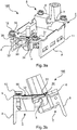
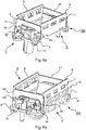
- FIGS. 1a, 1b . 2a and 2b is schematically shown a support frame 1 for connector modules 2, wherein in Fig. 2a and 2b the holding frame is open and in Fig. 1a and 1b closed is.
- the holding frame 1 is after the insertion of connector modules 2 for installation in connector housing (see DE 197 07 120 C1 and EP 0 860 906 A2 ) or for fixing over a breakthrough of a mounting surface / mounting wall provided.
- the support frame 1 consists of two connected via joints 3 holding frame halves 4, 5 with attachment ends 6, which can be provided with mounting screws (not shown), and side panels 8.
- the joints 3 are provided on the attachment ends 6 of the support frame 1, wherein the possibility of pivoting the frame halves 4, 5 is provided transversely to the side parts 8 of the holding frame 1 (as from the comparison of Fig. 1a, 1b and 2a, 2b can be seen).
- each formations are provided on the attachment ends 6 of the support frame 1, which engage in corresponding recesses. After introduction of the projections in the recesses, the side parts are pivotable about the longitudinal axis (rotatable).
- the connector modules 2 are provided with projecting, approximately rectangular holding means 9 and may have additional resilient latching hooks (not shown).
- additional resilient latching hooks (not shown).
- recesses 11 are provided, in which the support means 9 dive when inserting the connector modules 2 in the support frame 1.
- the possibly provided latching hooks can initially engage under the lower edges of the side parts 8 of the frame halves 4, 5 during insertion.
- the frame halves 4, 5 are capped together, d. H. the holding frame 1 is closed, wherein the holding means 9 reach into the recesses 11 and a secure, positive retention of the connector modules 2 in the holding frame 1 is effected.
- the attachment ends 6 each have a mounting portion which in the screwed-on state (see Fig. 1a and 1b ) extends parallel to the mounting surface (not shown).
- the extension plane of this attachment portion extends in the case of Fig. 1b horizontally and at right angles to the plane of the drawing.
- the projections 7 of the frame half 5 extend in the plane of extension in the direction of the frame half 4, more precisely in the recesses 10 of the frame half 4.
- the projections 7 and recesses 10 are respectively disposed at the outermost end of the fixing portions (in the longitudinal direction). Since the projections 7 thus to a certain extent enclose the opposite holding frame half 4 in the plane of extent, thus a relative displacement along the longitudinal axis for the frame half 4, 5 and thus also for the side parts 8 is prevented. In other words, it blocks in the presentation of Fig. 1a upper projection 7 in engagement with the corresponding recess 10 a movement obliquely right above (in the illustration), while the lower projection 7 in engagement with the corresponding recess 10 prevents a movement obliquely bottom left (in the illustration).
- the recess may also be slit-shaped, so that a lateral displacement of the side parts 8 in both directions is prevented by the engagement of a single projection.
- slot type is to be understood in this context that the recess has at least two opposite flanks, which abuts the projection, whereby the lateral displacement is prevented.
- This variant is therefore not limited to a slot as a return, as well as, for example, a return with the shape of a mushroom, a semicircle, a triangle, etc. are to be regarded as slit-shaped.
- each holding frame half each having a projection and a recess (at opposite ends).
- the projection 7 is designed as long as in this embodiment, that the engagement is not terminated even in the unfolded state of the support frame 1 (see Fig. 2b ), so that the prevention of lateral movement is maintained even in the unfolded state. This prevents the support frame from being unintentionally disassembled into its halves.
- FIGS. 1a, 1b . 2a and 2b holding frame are still shown without elastic fixing elements, this illustration is used to better understand the basic structure of a holding frame according to the invention.
- holding frame can have a security function against falling apart of the holding frame due to a displacement of the holding frame halves against each other in the longitudinal direction, as they FIGS. 1a, 1b . 2a and 2b can be seen.
- the invention also includes an embodiment of the holding frame halves such that a holding frame half in at least one attachment portion has a projecting towards the other holding frame half projection which engages in a recess in the mounting portion of the other holding frame half, so that a lateral displacement of the side parts is prevented.
- the holding frame halves can also be designed as substantially rigid die cast elements, in particular zinc, in which case can be dispensed with the backup function.
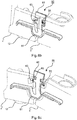
- FIGS. 3a and 3b show views of a first embodiment of a holding frame according to the invention.
- the basic construction of the support frame 100 is the shape of a hinged frame as shown in FIGS FIGS. 1a, 1b . 2a and 2b is shown or in DE 197 07 120 C1 and EP 0 860 906 A2 will describe.
- a spring blade 30 is fixed on a frame half 5 as an example of an elastic fixing element (here with rivets 35).
- the spring leaf 30 has two fingers 31, 32. The two fingers 31, 32 of the spring leaf extend into the region of the other, second frame half 4 and hold them in the closed position, ie the holding state, as shown in FIG Fig. 3a is shown.
- the holding frame 100 is pivoted against the force of the spring leaf 30, wherein finally the second finger 32 engages in a recess 34 on the other half of the holding frame 4 and thus fixes the support frame 100 in the open position (insertion state).
- the finger 32 is provided at its end with a nose 33 as an example of a locking element which engages in the recess 34.
- the recess 34 is an example of an engagement member.
- An advantage of dividing the spring blade 30 into two fingers 31, 32 is that when the finger 32 is lifted from the recess 34, the other finger 31 already urges the other holding frame half 4 in the direction of the holding state (clockwise in FIG Fig. 3b ).
- both fingers of the spring leaf may be provided with a nose which engages in a respective recess for fixing, wherein the nose of a finger and the corresponding recess in the other half of the holding frame for fixing the insertion state and the nose of the other finger and the corresponding recess for Fixation of the holding state serve.
- the spring leaf is not divided into two fingers, and thereby has a nose which can engage either in one or two recesses to fix one or both states.
- FIG. 3b Another modification may be that the support of the spring leaf is not as in FIG. 3b shown on the surface of the attachment end 6 but located at an edge of the other half of the holding frame, so that an interaction of this edge can be used with a projection on the spring leaf to a fixation.
- Fig. 3b It can be seen that a spring leaf attached to the holding frame half 5 would come into contact with the lower half edge of the holding frame half 4 facing the holding frame half 5 during pivoting and would thereby be put under tension.
- a division of the spring blade could cause a finger (comparable to finger 31) provides a restoring force acting in the direction of the holding state, the other, shorter finger (comparable to finger 32) comes off the edge and with the inner half of the holding frame half 4 directed towards the holding frame half 5 reaches a fixation which can be released by a spreading apart of the shorter finger.
- a two-part frame is provided which is brought into an open end position solely by the rotation of the frame halves by means of spring force and engages there. From the open end position he (only) by unlocking the locking finger spring back into the closed position and then remains in this.
- a reversal of the constellation can be achieved, so that the spring leaf causes a restoring force in the direction of the insertion state in a state between the inserted state and the holding state, wherein a nose or other latching element for engagement with a Engagement element (eg a recess) is configured in the holding state.
- a nose or other latching element for engagement with a Engagement element eg a recess
- the latching element is a nose 33 and the engagement element 34 is a recess.
- the engagement element is formed by a projection or the like on the holding frame half, wherein the detent element e.g. may be an opening in the spring leaf. Combinations of nose and projection or similar structures are also possible.
- FIGS. 4a and 4b show views of a second embodiment of a holding frame according to the invention.
- the insertion state (dashed line) and the holding state is shown in each case, wherein the FIGS. 4a and 4b differ in the opposite direction.
- the basic construction of the holding frame 200 is, similar to the first embodiment, the shape of a hinge frame, as in the FIGS. 1a, 1b . 2a and 2b is shown or in DE 197 07 120 C1 and EP 0 860 906 A2 will describe.
- two different locking plates 40, 41 are provided as further examples of elastic fixing elements.
- the locking plates 40, 41 are designed so that on one side a cylindrical mandrel 44 of the holding frame surface 4 in two recesses 43, 46 on or in the locking plate 40, 41 can engage.
- the other side is firmly connected to the holding frame half (here by screws 45).
- the recesses are designed so that the holding frame 200 is fixed in an open and a closed position.
- the locking plates 40, 41 are different variants of an elastic fixing element and can be used either individually, in duplicate or, as shown here, in mixture.
- Fig. 4a It can be seen that the mandrel 44 extends in the holding state through the upper of the two recesses 43 of the locking plate 41, while extending in the inserted state through the lower of the two recesses 43.
- the locking plate 41 has a spring property in this direction and can therefore be considered as a spring leaf.
- a corresponding mandrel 44 is in each case in the holding state and in the inserted state in a recess or notch 46 of the locking plate 40, which are provided on the inside of the U-shaped locking plate 40.
- the locking plate 40 also has an elasticity in the frontal plane, so that with a sufficient force by a small spreading of the U-shape of the mandrel 44 is released from the respective notch 46 and can get along the leg of the locking plate to each other notch 46. So here there is no positive connection but only a traction for fixation.
- An advantage of a combination of the locking plates 40, 41 is that for the respective release not both sides must be unlocked by Abspreizen to bring the holding frame in the open or closed position.
- FIGS. 5a, 5b and 5c show views of a third embodiment of a holding frame according to the invention.
- the basic construction of the support frame 300 is similar to the first and second embodiments, the shape of a hinge frame, as in the FIGS. 1a, 1b . 2a and 2b is shown or in DE 197 07 120 C1 and EP 0 860 906 A2 will describe.
- clamp springs 50 are provided, wherein the clamp springs are each provided on the inside of the end face parts so that a in Substantially flush surface forms. This flush shape prevents it from jamming or the like when inserting a plug-in module (not shown).
- Each clip spring 50 per se is an example of an elastic fixing element.
- the clamp spring 50 holds the two holding frame halves 4, 5 together under a certain bias.
- Fig. 5b is in the closed state (holding state) by acting on the holding frame halves 4, 5 end points 51 of the staple spring 50 certain line of action 52 of the biasing force by a certain amount above the joint 3 and defined by the hinge 3 pivot axis or a appropriate Plane 53.
- This causes the support frame 300 to be held in the closed position because counterclockwise torque acts on the hinge 3 by the biasing force of the spring (see arrow 54).
- the effect of the clamp spring 50 used here can be explained in other ways.
- the holding frame halves 4, 5 and the clamp spring 50 are arranged and designed in this case so that the distance between the end points 51 (or points of attack) of the clamp spring assumes an at least local minimum in the holding state and in the plug-in state. To get about from the holding state to the insertion state, therefore, the staple spring must be spread against their respective restoring force.
- the distance between the end points 51 is maximum, so that after overcoming this point further pivoting is supported by the restoring force of the staple spring 50.
- the maximum of the distance between the end points is preferably only at one point, which thus defines a labile maximum between the two states.
- FIGS. 6a . 6b and 6c show views of a fourth embodiment of a holding frame according to the invention.
- the basic construction of the support frame 400 is similar to the shape of a hinged frame as shown in FIGS FIGS. 1a, 1b . 2a and 2b is shown or in DE 197 07 120 C1 and EP 0 860 906 A2 is described. Unlike in the first, second and third embodiment, however, here is not formed by a projection and recess joint (see, eg Fig. 1b or 2 B ) intended.
- the articulated connection of the holding frame halves 4 ', 5' of the holding frame 400 is achieved here by a part of an omega spring 60 as an example of an elastic fixing element.
- the omega spring 60 includes a hinge portion 61 and a latch portion 62.
- the hinge portion 61 extends in corresponding recesses of the holding frame halves 4 ', 5' and obtained in this embodiment by pivoting the holding frame halves 4 ', 5' from the holding state (see Fig. 6b ) in the inserted state (see Fig. 6c ), a bending stress by which the holding frame 400 tends to return to the holding state.
- the latching portion 62 is connected to the hinge portion 61 and allows - against a restoring force - an elastic deformation along the longitudinal axis of the holding frame, so that a bending stress can be built up.
- two projections 63 of the latching portion 62 extend into corresponding recesses 64 of the holding frame halves 4 ', 5', so that the holding frame is fixed in addition to the action of the hinge portion 61 in the holding state by locking.
- the locking portion 62 is bent so that the projections 63 come free from the recesses 64. With such a release of the support frame can be spread against the restoring force applied by the joint portion and thus brought into the inserted state.
- the projections 63 move between the inner edges 65 of the holding frame halves 4 ', 5', so that by a cooperation of the inner edges 65 (or possible recesses therein) with the projections 63 a return of the holding frame 400 in the holding state is prevented.
- the holding frame halves can be configured identically to one another, since the asymmetry given by the joint in the other exemplary embodiments is no longer necessary.
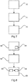
- Fig. 7 shows a flowchart for illustrating an embodiment of a manufacturing method according to the invention.
- the manufacturing method is used to produce a holding frame according to the invention, ie a holding frame for holding connector modules, so that the connector modules can be inserted into the holding frame and plug module holding means on the connector modules can cooperate with provided on opposite side parts of the holding frame holding frame holding means.
- a first step 70 two holding frame halves are provided, each with a side portion of the holding frame, are hinged together at attachment ends in a following step 71, wherein the articulated connection allows a plug-in state and a holding state of the holding frame, wherein in the inserted state, the holding frame halves in such a Longitudinal axis are pivoted to each other, that one or more connector modules between the side parts can be introduced, wherein in the holding state, the holding frame halves are pivoted relative to the inserted state that one or more inserted connector modules have a positive connection with the holding frame via the support means.
- the method further comprises a step of attaching 72 at least one elastic fixing element, which is designed for releasably fixing the holding frame halves in the inserted state and the holding state, wherein at least to solve the fixation and / or to a change between the insertion and holding state, a restoring force of the elastic Fixing element is overcome.
- the attachment 72 of the elastic fixing element is effected by a positive, non-positive and / or material connection.
- steps 70, 71 and 72 are not necessary for the manufacturing process.
- the attaching step 72 may also be part of the provision 70 of the holding frame halves and / or between steps 70 and 71.
- Fig. 8 shows a flowchart illustrating an embodiment of an assembly method according to the invention.
- the method according to the invention for equipping a holding frame with connector modules, in particular a holding frame, as described here and shown in the figures, comprises the following steps: First, in step 80, an inserting state of the holding frame is provided, wherein in the insertion state, the two hinged at attachment ends of the holding frame holding frame halves are pivoted to each other about a longitudinal axis to one another that one or more connector modules between the side parts can be introduced.
- the provisioning step 80 comprises detachably fixing the holding frame halves 81 to each other by an elastic fixing member.
- the holding frame can be equipped in a loading step 82 with one or more connector modules.
- the loading 82 is followed by provision 83 of a holding state of the holding frame with pivoting of the holding frame halves relative to the inserting state such that the one or more inserted connector modules form-fit via plug-in module retention means to the connector modules and to support frame support means provided on opposite side portions of the support frame having the holding frame.
- the provision 83 of the holding state comprises releasably fixing 84 of the holding frame halves to each other by the elastic spring member.
- the fixing 84 in the holding state is a overcoming 85 of a restoring force of the elastic spring element at least for solving the fixation in the inserted state and / or to a change between the insertion and holding state ahead.
- the invention preferably allows a clearly fixed open frame position for the assembly or insertion of the modules. After insertion of the modules in the frame and the positioning of the frame halves in the closed state, this is against unintentional opening within certain limits or at least in Secured frame of its normal handling, without the need to install an additional security element.
- a defined electrical contact between the frame halves is achieved by the elastic fixing.
- a fixation of the frame halves in the open / closed state can thus be integrated in the support frame itself, so that no losable items vorlägen. Unintentional opening of the holding frame halves after assembly or insertion of the modules is prevented by spring force.
Landscapes
- Connector Housings Or Holding Contact Members (AREA)
- Mirrors, Picture Frames, Photograph Stands, And Related Fastening Devices (AREA)
- Clamps And Clips (AREA)
Claims (15)
- Châssis de maintien (100, 200, 300, 400) servant à fixer des modules de connecteur enfichable (2),
dans lequel les modules de connecteur enfichable (2) peuvent être utilisés dans le châssis de maintien (100, 200, 300, 400) et des moyens de fixation de module enfichable (9) coopèrent, au niveau des modules de connecteur enfichable (2), avec des moyens de fixation de châssis de maintien (11) prévus au niveau de parties latérales (8) opposées du châssis de maintien (100, 200, 300, 400),
dans lequel le châssis de maintien (100, 200, 300, 400) comprend deux moitiés de châssis de maintien (4, 4', 5, 5') reliées l'une à l'autre de manière articulée au niveau d'extrémités de fixation (6) du châssis de maintien (100, 200, 300, 400), dans lequel la séparation du châssis de maintien (100, 200, 300, 400) est prévue de manière parallèle par rapport aux parties latérales (8) du châssis de maintien (100, 200, 300, 400),
dans lequel la liaison (3, 60) articulée permet un état d'enfichage et un état de maintien du châssis de maintien (100, 200, 300, 400),
dans lequel les moitiés de châssis de maintien (4, 4', 5, 5') sont pivotées l'une par rapport à l'autre dans l'état d'enfichage de telle manière, autour d'un axe longitudinal, qu'un ou plusieurs modules de connecteur enfichable (2) peuvent être introduits entre les parties latérales (8), et
dans lequel les moitiés de châssis de maintien (4, 4', 5, 5') sont pivotées dans l'état de maintien de telle manière par rapport à l'état d'enfichage qu'un ou plusieurs modules de connecteur enfichable (2) utilisés présentent, au-dessus des moyens de fixation (9, 11), une liaison par complémentarité de forme avec le châssis de maintien (100, 200, 300, 400),
caractérisé en ce que
le châssis de maintien (100, 200, 300, 400) présente un élément de blocage élastique (30, 40, 41, 50, 60), qui est configuré aux fins d'un blocage amovible des moitiés de châssis de maintien (4, 4', 5, 5') dans l'état d'enfichage et dans l'état de maintien, dans lequel une force de rappel de l'élément de blocage élastique (30, 40, 41, 50, 60) doit être surmontée au moins aux fins du desserrage du blocage et/ou aux fins d'un passage entre l'état d'enfichage et l'état de maintien. - Châssis de maintien (100, 200) selon la revendication 1,
dans lequel l'élément de blocage élastique (30, 40) comprend une lame de ressort (30, 40) installée au niveau d'une moitié de châssis de maintien (5) avec un élément d'enclenchement (33, 43, 46) en vue d'une prise avec un élément de prise (34, 44) de l'autre moitié de châssis de maintien (4). - Châssis de maintien (100) selon la revendication 2, dans lequela) la lame de ressort (30) est configurée dans un état entre l'état d'enfichage et l'état de maintien pour provoquer une force de rappel en direction de l'état de maintien et l'élément d'enclenchement (33) est configuré en vue de la prise avec l'élément de prise (34) dans l'état d'enfichage, oub) la lame de ressort est configurée dans un état entre l'état d'enfichage et l'état de maintien afin de provoquer une force de rappel en direction de l'état d'enfichage et l'élément d'enclenchement est configuré en vue de la prise avec l'élément de prise dans l'état de maintien.
- Châssis de maintien (100, 200) selon la revendication 2 ou 3,
dans lequel il faut contrecarrer une force de rappel de la lame de ressort (30, 40, 41) afin de desserrer la prise de l'élément d'enclenchement (33, 43, 56) et de l'élément de prise (34, 44). - Châssis de maintien (100, 200) selon l'une quelconque des revendications 2 à 4,
dans lequel l'autre moitié de châssis de maintien (4) présente un premier élément de prise et un deuxième élément de prise, et
l'élément d'enclenchement est configuré en vue d'une prise avec le premier et le deuxième élément de prise ou la lame de ressort (30, 40, 41) présente un deuxième élément d'enclenchement. - Châssis de maintien (300) selon la revendication 1, dans lequel la liaison articulée est configurée de telle manière qu'un éloignement entre une première section (51) d'une moitié de châssis de maintien (4) et une seconde section (51) de l'autre moitié de châssis de maintien (5) adopte une valeur extrême dans le cas d'un passage entre l'état d'enfichage et l'état de maintien, dans lequel la première et la seconde section (51) sont couplées l'une à l'autre par l'intermédiaire de l'élément de blocage élastique (50).
- Châssis de maintien (300) selon la revendication 1 ou 6,
dans lequel une première section (51) d'une moitié de châssis de maintien (4) et une seconde section (51) de l'autre moitié de châssis de maintien (5) sont couplées l'une à l'autre par l'intermédiaire de l'élément de ressort élastique (50), dans lequel un axe de pivotement de la liaison (3) articulée entre une ligne de liaison (52) entre la première et la seconde section (51) se trouve dans l'état d'enfichage et une ligne de liaison (52) entre la première et la seconde section (51) dans l'état de maintien. - Châssis de maintien (300) selon la revendication 6 ou 7,
dans lequel l'élément de ressort élastique (50) est un ressort de serrage (50), qui est disposé en particulier dans un plan défini par un élément de fixation (6). - Châssis de maintien (400) selon la revendication 1, dans lequel l'élément de blocage élastique (60) comprend une section articulée (61) et une section d'enclenchement (62),
dans lequel la section articulée (61) relie l'une à l'autre de manière articulée les moitiés de châssis de maintien (4', 5') de sorte que, dans l'état d'enfichage, une première force de rappel d'articulation agit en direction de l'état de maintien et/ou dans l'état de maintien, une deuxième force de rappel d'articulation agit en direction de l'état d'enfichage,
dans lequel la section d'enclenchement (62) maintient dans une position d'enclenchement les moitiés de châssis de maintien (4', 5') dans l'état d'enfichage à l'encontre de la première force de rappel d'articulation ou dans l'état de maintien à l'encontre de la deuxième force de rappel d'articulation, et dans lequel la section d'enclenchement (62) peut être amenée à l'encontre de la force de rappel d'enclenchement de la position d'enclenchement dans une position de libération, dans laquelle la section d'enclenchement (62) permet un passage entre un état de maintien et un état d'enfichage. - Châssis de maintien (400) selon la revendication 9,
dans lequel la section articulée (61) et la section d'enclenchement (62) sont réalisées conjointement d'un seul tenant sous la forme d'éléments de l'élément de blocage élastique (60). - Châssis de maintien (400) selon la revendication 9 ou 10,
dans lequel la section articulée (61) est desserrée dans l'état d'enfichage ou dans l'état de maintien, dans lequel la section d'enclenchement (62) est configurée en vue d'un blocage des moitiés de châssis de maintien (4', 5') quand la section articulée (61) est desserrée. - Châssis de maintien (400) selon la revendication 9 ou 10,
dans lequel la section articulée (61) est configurée en vue d'un maintien de l'état d'enfichage ou de l'état de maintien par l'intermédiaire de la première ou la deuxième force de rappel d'articulation. - Châssis de maintien (100, 200, 300, 400) selon l'une quelconque des revendications précédentes,
dans lequel l'élément de ressort élastique (30, 40, 41, 50, 60) relie les moitiés de châssis de maintien (4, 5) l'une à l'autre de manière électrique au moins dans l'état de maintien. - Procédé servant à fabriquer un châssis de maintien (100, 200, 300, 400) servant à fixer des modules de connecteur enfichable (2) de sorte que les modules de connecteur enfichable (2) peuvent être utilisés dans le châssis de maintien (100, 200, 300, 400) et des moyens de fixation de module enfichable (9) au niveau des modules de connecteur enfichable (2) peuvent coopérer avec des moyens de fixation de châssis de maintien (11) prévus au niveau de parties latérales (8) opposées du châssis de maintien (100, 200, 300, 400), avec les étapes de :la prévision (70) de deux moitiés de châssis de maintien (4, 4', 5, 5') avec respectivement une partie latérale (8) du châssis de maintien (100, 200, 300, 400), etla liaison articulée (71) des moitiés de châssis de maintien (4, 4', 5, 5') au niveau d'extrémités de fixation (6) l'une à l'autre le long des parties latérales (8) du châssis de maintien (100, 200, 300, 400),dans lequel la liaison articulée (3, 60) permet un état d'enfichage et un état de maintien du châssis de maintien (100, 200, 300, 400), dans lequel, dans l'état d'enfichage, les moitiés de châssis de maintien (4, 4', 5, 5') sont pivotées l'une par rapport à l'autre de telle manière, autour d'un axe longitudinal, qu'un ou plusieurs modules de connecteur enfichable (2) peuvent être introduits entre les parties latérales (8), dans lequel, dans l'état de maintien, les moitiés de châssis de maintien (4, 4', 5, 5') sont pivotées de telle manière par rapport à l'état d'enfichage qu'un ou plusieurs modules de connecteur enfichable (2) utilisés présentent, au-dessus des moyens de fixation (9, 11), une liaison par complémentarité de forme avec le châssis de maintien (100, 200, 300, 400),caractérisé parla mise en place (72) d'un élément de blocage élastique (30, 40, 41, 50, 60), qui est configuré en vue d'un blocage amovible des moitiés de châssis de maintien (4, 4', 5, 5') dans l'état d'enfichage et dans l'état de maintien, dans lequel une force de rappel de l'élément de blocage élastique (30, 40, 41, 50, 60) doit être surmontée au moins aux fins du desserrage du blocage et/ou d'un changement entre l'état d'enfichage et l'état de maintien,dans lequel la mise en place (72) de l'élément de blocage élastique (30, 40, 41, 50, 60) est effectuée par l'intermédiaire d'une liaison par complémentarité de forme, à force et/ou liaison de matière.
- Procédé servant à équiper un châssis de maintien (100, 200, 300, 400) avec des modules de connecteur enfichable (2), des châssis de maintien (100, 200, 300, 400) selon l'une quelconque des revendications précédentes 1 à 13, dans lequel le châssis de maintien (100, 200, 300, 400) comprend deux moitiés de châssis de maintien (4, 4', 5, 5'), dans lequel la séparation du châssis de maintien (100, 200, 300, 400) est prévue de manière parallèle par rapport aux parties latérales du châssis de maintien (100, 200, 300, 400), avec les étapes de :la prévision (80) d'un état d'enfichage du châssis de maintien (100, 200, 300, 400), dans lequel, dans l'état d'enfichage, les deux moitiés de châssis de maintien (4, 4', 5, 5') reliées l'une à l'autre de manière articulée au niveau d'extrémités de fixation du châssis de maintien (100, 200, 300, 400) sont pivotées l'une par rapport à l'autre de telle manière, autour d'un axe longitudinal, qu'un ou plusieurs modules de connecteur enfichable (2) peuvent être introduits entre les parties latérales (8),dans lequel la prévision (80) de l'état d'enfichage comprend un blocage (81) amovible des moitiés de châssis de maintien (4, 4', 5, 5') l'une par rapport à l'autre par l'intermédiaire d'un élément de blocage élastique (30, 40, 41, 50, 60),l'équipement (82) du châssis de maintien (100, 200, 300, 400) dans l'état d'enfichage avec un ou plusieurs modules de connecteur enfichable (2), etla prévision (83) d'un état de maintien du châssis de maintien (100, 200, 300, 400) par l'intermédiaire du pivotement des moitiés de châssis de maintien (4, 4', 5, 5') par rapport à l'état d'enfichage de sorte qu'un ou les plusieurs modules de connecteur enfichable (2) utilisés présentent une liaison par complémentarité de forme avec le châssis de maintien (100, 200, 300, 400) par l'intermédiaire de moyens de fixation de module enfichable (9) au niveau des modules de connecteur enfichable (2) et des moyens de fixation de châssis de maintien (11) prévus au niveau de parties latérales (8) opposées du châssis de maintien (100, 200, 300, 400),dans lequel la prévision (83) de l'état de maintien comprend un blocage (84) amovible des moitiés de châssis de maintien (4, 4', 5, 5') l'une par rapport à l'autre par l'intermédiaire de l'élément de ressort élastique (30, 40, 41, 50, 60),dans lequel la prévision (83) de l'état de maintien comprend au moins, aux fins du desserrage du blocage dans l'état d'enfichage et/ou aux fins d'un changement entre l'état d'enfichage et l'état de maintien, l'action de surmonter (85) une force de rappel de l'élément de blocage élastique (30, 40, 41, 50, 60) .
Priority Applications (1)
| Application Number | Priority Date | Filing Date | Title |
|---|---|---|---|
| PL16754222T PL3286806T3 (pl) | 2015-09-03 | 2016-08-02 | Ramka mocująca do zamocowania modułów łącznika wtykowego |
Applications Claiming Priority (2)
| Application Number | Priority Date | Filing Date | Title |
|---|---|---|---|
| DE102015216929.4A DE102015216929A1 (de) | 2015-09-03 | 2015-09-03 | Halterahmen zur Halterung von Steckverbindermodulen |
| PCT/EP2016/068430 WO2017036707A1 (fr) | 2015-09-03 | 2016-08-02 | Châssis de maintien permettant de maintenir des modules de connecteur à fiche |
Publications (2)
| Publication Number | Publication Date |
|---|---|
| EP3286806A1 EP3286806A1 (fr) | 2018-02-28 |
| EP3286806B1 true EP3286806B1 (fr) | 2018-07-18 |
Family
ID=56741022
Family Applications (1)
| Application Number | Title | Priority Date | Filing Date |
|---|---|---|---|
| EP16754222.4A Active EP3286806B1 (fr) | 2015-09-03 | 2016-08-02 | Châssis de maintien permettant de maintenir des modules de connecteur à fiche |
Country Status (6)
| Country | Link |
|---|---|
| US (1) | US9577365B1 (fr) |
| EP (1) | EP3286806B1 (fr) |
| CN (1) | CN108028490B (fr) |
| DE (1) | DE102015216929A1 (fr) |
| PL (1) | PL3286806T3 (fr) |
| WO (1) | WO2017036707A1 (fr) |
Families Citing this family (24)
| Publication number | Priority date | Publication date | Assignee | Title |
|---|---|---|---|---|
| DE102014215809A1 (de) * | 2014-08-08 | 2016-02-11 | Harting Electric Gmbh & Co. Kg | Halterahmen und Verfahren zu seiner Herstellung |
| DE102015101433B3 (de) * | 2015-02-02 | 2016-06-16 | Harting Electric Gmbh & Co. Kg | Halterahmen für Steckverbindermodule |
| DE102015114696B4 (de) * | 2015-09-03 | 2020-10-29 | Harting Electric Gmbh & Co. Kg | Halterahmen für Steckverbindermodule |
| DE102015114698A1 (de) * | 2015-09-03 | 2017-03-30 | Harting Electric Gmbh & Co. Kg | Halterahmen für Steckverbindermodule |
| DE102015114699A1 (de) | 2015-09-03 | 2017-03-09 | Harting Electric Gmbh & Co. Kg | Halterahmen für Steckverbindermodule |
| DE102015114702B4 (de) * | 2015-09-03 | 2019-01-31 | Harting Electric Gmbh & Co. Kg | Halterahmen |
| DE102015114697B4 (de) * | 2015-09-03 | 2020-03-26 | Harting Electric Gmbh & Co. Kg | Halterahmen für Steckverbindermodule |
| DE102015114703B4 (de) * | 2015-09-03 | 2020-03-26 | Harting Electric Gmbh & Co. Kg | Halterahmen für Steckverbindermodule |
| DE102015114700B4 (de) | 2015-09-03 | 2020-08-06 | Harting Electric Gmbh & Co. Kg | Halterahmen |
| PL3345257T3 (pl) * | 2015-09-03 | 2021-03-08 | Harting Electric Gmbh & Co. Kg | Rama przytrzymująca do modułów złączy wtykowych |
| DE102015114701B4 (de) | 2015-09-03 | 2019-01-31 | Harting Electric Gmbh & Co. Kg | Halterahmen mit Sperrelement |
| DE102015222561B4 (de) | 2015-11-16 | 2018-05-30 | Harting Electric Gmbh & Co. Kg | Halterahmen zur Halterung von Steckverbindermodulen |
| FR3047358B1 (fr) * | 2016-01-28 | 2020-07-17 | Safran Electrical & Power | Platine de connexion de harnais electriques |
| DE102016106479A1 (de) * | 2016-04-08 | 2017-10-12 | Phoenix Contact Gmbh & Co. Kg | Rangierwabe |
| DE102017105077B4 (de) | 2017-03-10 | 2018-09-20 | Phoenix Contact Gmbh & Co. Kg | Kontakteinsatz für ein Steckverbinderteil |
| BE1025553B1 (de) * | 2017-08-16 | 2019-04-09 | Phoenix Contact Gmbh & Co. Kg | Baugruppe eines Steckverbinderteils mit einem Halterahmen und daran ansetzbare modulare Kontakteinsätze |
| BE1025564B1 (de) * | 2017-09-19 | 2019-04-19 | Phoenix Contact Gmbh & Co Kg | Modularer Anschlussblock mit einer Mehrzahl von Anschlussmodulen für ein Elektronikbauteil |
| DE102017125859A1 (de) * | 2017-11-06 | 2019-05-09 | Harting Electric Gmbh & Co. Kg | Modularer Halterahmen für Steckverbinder |
| DE102018115371A1 (de) * | 2018-06-26 | 2020-01-02 | Harting Electric Gmbh & Co. Kg | Steckverbindermodul für einen Industriesteckverbinder |
| DE102019112612B3 (de) * | 2019-05-14 | 2020-10-01 | Phoenix Contact Gmbh & Co. Kg | Halterahmen und Steckverbinder mit einem derartigen Halterahmen |
| EP3961831A1 (fr) * | 2020-08-27 | 2022-03-02 | TE Connectivity Germany GmbH | Mécanisme de retenue pour la fixation d'une unité d'équipement technique sur un rail de montage et unité d'équipement technique doté d'un tel mécanisme de retenue |
| TWI813989B (zh) * | 2021-05-05 | 2023-09-01 | 精英電腦股份有限公司 | 活動式鎖耳及包含其的電子裝置 |
| CN116581587A (zh) * | 2023-07-11 | 2023-08-11 | 深圳市格瑞达电力连接器件有限公司 | 一种端子连接器组合、连接器组合及连接器套装 |
| CN116826429B (zh) * | 2023-08-30 | 2023-10-31 | 东北林业大学 | 一种多头电力线连接器 |
Family Cites Families (6)
| Publication number | Priority date | Publication date | Assignee | Title |
|---|---|---|---|---|
| DE19707120C1 (de) | 1997-02-22 | 1998-06-25 | Harting Kgaa | Halterahmen |
| DE20205787U1 (de) * | 2002-04-13 | 2002-07-25 | Harting Electric Gmbh & Co Kg | Modularer Steckverbinder |
| CN202084755U (zh) * | 2011-04-28 | 2011-12-21 | 中航光电科技股份有限公司 | 一种连接器模块结构及其固定框架 |
| SI2581991T1 (sl) * | 2011-10-13 | 2017-03-31 | Weidmueller Interface Gmbh & Co. Kg | Držalni okvir za vtični konektor |
| CN202352910U (zh) * | 2011-12-15 | 2012-07-25 | 四川华丰企业集团有限公司 | 一种新型重载连接器用矩形活动框架 |
| CN204271392U (zh) * | 2014-12-10 | 2015-04-15 | 资阳南车电气有限公司 | 连接器模块固定框架 |
-
2015
- 2015-09-03 DE DE102015216929.4A patent/DE102015216929A1/de not_active Withdrawn
- 2015-11-18 US US14/945,239 patent/US9577365B1/en active Active
-
2016
- 2016-08-02 EP EP16754222.4A patent/EP3286806B1/fr active Active
- 2016-08-02 CN CN201680051275.5A patent/CN108028490B/zh active Active
- 2016-08-02 PL PL16754222T patent/PL3286806T3/pl unknown
- 2016-08-02 WO PCT/EP2016/068430 patent/WO2017036707A1/fr unknown
Non-Patent Citations (1)
| Title |
|---|
| None * |
Also Published As
| Publication number | Publication date |
|---|---|
| CN108028490A (zh) | 2018-05-11 |
| EP3286806A1 (fr) | 2018-02-28 |
| PL3286806T3 (pl) | 2019-01-31 |
| US20170069998A1 (en) | 2017-03-09 |
| DE102015216929A1 (de) | 2017-03-09 |
| WO2017036707A1 (fr) | 2017-03-09 |
| US9577365B1 (en) | 2017-02-21 |
| CN108028490B (zh) | 2019-08-20 |
Similar Documents
| Publication | Publication Date | Title |
|---|---|---|
| EP3286806B1 (fr) | Châssis de maintien permettant de maintenir des modules de connecteur à fiche | |
| DE2534472C2 (fr) | ||
| EP3345256B1 (fr) | Châssis de maintien pour module de connecteur à fiche comprenant un étrier de verrouillage qui peut être fixé | |
| EP3178135B1 (fr) | Cadre de retenue et procédé de fabrication dudit cadre de retenue | |
| DE102015222561B4 (de) | Halterahmen zur Halterung von Steckverbindermodulen | |
| EP3080874A1 (fr) | Cadre de retenue pour un connecteur par enfichage | |
| DE202007001780U1 (de) | Schubkasten | |
| EP3345257A1 (fr) | Châssis de maintien pour modules de connecteur à fiche | |
| EP3345259A1 (fr) | Cadre de maintien pour modules de connecteurs enfichables comprenant un élément de blocage précontraint | |
| DE102017119287A1 (de) | Modularer Steckverbinder für Leiterplatten | |
| DE102006029381B4 (de) | Steckverbinder an einem Bauteil, der in einem Loch einer Basis-Platte zu befestigen ist | |
| DE102017108432A1 (de) | Halterahmen für einen Steckverbinder und Verfahren zur Bestückung | |
| EP3843221A1 (fr) | Cadre de support pour un connecteur | |
| DE19534205C2 (de) | Elektrischer Steckverbinder | |
| DE202012011094U1 (de) | Rollen- oder Flyerkette mit wenigstens einem Anbauteil | |
| DE102019112612B3 (de) | Halterahmen und Steckverbinder mit einem derartigen Halterahmen | |
| DE102019113069B3 (de) | Halterahmen und Steckverbinder mit einem derartigen Halterahmen | |
| EP3608588B1 (fr) | Ressort de maintien pour luminaire | |
| DE10102453A1 (de) | Gehäuse zur Aufnahme eines steckbar mit dem Gehäuse verbindbaren Bauteils | |
| DE102019106093B4 (de) | Halterahmen sowie Steckverbinder mit einem derartigen Halterahmen | |
| DE102008040848A1 (de) | Wischerarm mit einer Wischerblattbefestigungseinrichtung | |
| DE102019104723B4 (de) | Schaltschrankanordnung mit einem Schaltschrank und mindestens einer Steckdosenleiste | |
| EP1936754A2 (fr) | Connecteur à fiches doté d'un boîtier comportant un élément d'actionnement et un moyen d'accrochage | |
| DE202010004995U1 (de) | Befestiger zur Befestigung eines ersten Bauteils an einem zweiten Bauteil | |
| DE102008007135A1 (de) | Befestigungselement |
Legal Events
| Date | Code | Title | Description |
|---|---|---|---|
| PUAI | Public reference made under article 153(3) epc to a published international application that has entered the european phase |
Free format text: ORIGINAL CODE: 0009012 |
|
| 17P | Request for examination filed |
Effective date: 20171124 |
|
| AK | Designated contracting states |
Kind code of ref document: A1 Designated state(s): AL AT BE BG CH CY CZ DE DK EE ES FI FR GB GR HR HU IE IS IT LI LT LU LV MC MK MT NL NO PL PT RO RS SE SI SK SM TR |
|
| AX | Request for extension of the european patent |
Extension state: BA ME |
|
| GRAP | Despatch of communication of intention to grant a patent |
Free format text: ORIGINAL CODE: EPIDOSNIGR1 |
|
| RIC1 | Information provided on ipc code assigned before grant |
Ipc: H01R 13/514 20060101ALN20180312BHEP Ipc: H01R 9/26 20060101ALN20180312BHEP Ipc: H01R 13/518 20060101AFI20180312BHEP |
|
| DAV | Request for validation of the european patent (deleted) | ||
| DAX | Request for extension of the european patent (deleted) | ||
| INTG | Intention to grant announced |
Effective date: 20180326 |
|
| GRAS | Grant fee paid |
Free format text: ORIGINAL CODE: EPIDOSNIGR3 |
|
| GRAA | (expected) grant |
Free format text: ORIGINAL CODE: 0009210 |
|
| AK | Designated contracting states |
Kind code of ref document: B1 Designated state(s): AL AT BE BG CH CY CZ DE DK EE ES FI FR GB GR HR HU IE IS IT LI LT LU LV MC MK MT NL NO PL PT RO RS SE SI SK SM TR |
|
| REG | Reference to a national code |
Ref country code: GB Ref legal event code: FG4D Free format text: NOT ENGLISH |
|
| REG | Reference to a national code |
Ref country code: CH Ref legal event code: EP |
|
| REG | Reference to a national code |
Ref country code: IE Ref legal event code: FG4D Free format text: LANGUAGE OF EP DOCUMENT: GERMAN |
|
| REG | Reference to a national code |
Ref country code: AT Ref legal event code: REF Ref document number: 1020366 Country of ref document: AT Kind code of ref document: T Effective date: 20180815 |
|
| REG | Reference to a national code |
Ref country code: DE Ref legal event code: R096 Ref document number: 502016001473 Country of ref document: DE |
|
| REG | Reference to a national code |
Ref country code: FR Ref legal event code: PLFP Year of fee payment: 3 |
|
| REG | Reference to a national code |
Ref country code: NL Ref legal event code: MP Effective date: 20180718 |
|
| REG | Reference to a national code |
Ref country code: LT Ref legal event code: MG4D |
|
| PG25 | Lapsed in a contracting state [announced via postgrant information from national office to epo] |
Ref country code: NL Free format text: LAPSE BECAUSE OF FAILURE TO SUBMIT A TRANSLATION OF THE DESCRIPTION OR TO PAY THE FEE WITHIN THE PRESCRIBED TIME-LIMIT Effective date: 20180718 |
|
| PG25 | Lapsed in a contracting state [announced via postgrant information from national office to epo] |
Ref country code: BG Free format text: LAPSE BECAUSE OF FAILURE TO SUBMIT A TRANSLATION OF THE DESCRIPTION OR TO PAY THE FEE WITHIN THE PRESCRIBED TIME-LIMIT Effective date: 20181018 Ref country code: NO Free format text: LAPSE BECAUSE OF FAILURE TO SUBMIT A TRANSLATION OF THE DESCRIPTION OR TO PAY THE FEE WITHIN THE PRESCRIBED TIME-LIMIT Effective date: 20181018 Ref country code: RS Free format text: LAPSE BECAUSE OF FAILURE TO SUBMIT A TRANSLATION OF THE DESCRIPTION OR TO PAY THE FEE WITHIN THE PRESCRIBED TIME-LIMIT Effective date: 20180718 Ref country code: GR Free format text: LAPSE BECAUSE OF FAILURE TO SUBMIT A TRANSLATION OF THE DESCRIPTION OR TO PAY THE FEE WITHIN THE PRESCRIBED TIME-LIMIT Effective date: 20181019 Ref country code: LT Free format text: LAPSE BECAUSE OF FAILURE TO SUBMIT A TRANSLATION OF THE DESCRIPTION OR TO PAY THE FEE WITHIN THE PRESCRIBED TIME-LIMIT Effective date: 20180718 Ref country code: IS Free format text: LAPSE BECAUSE OF FAILURE TO SUBMIT A TRANSLATION OF THE DESCRIPTION OR TO PAY THE FEE WITHIN THE PRESCRIBED TIME-LIMIT Effective date: 20181118 Ref country code: FI Free format text: LAPSE BECAUSE OF FAILURE TO SUBMIT A TRANSLATION OF THE DESCRIPTION OR TO PAY THE FEE WITHIN THE PRESCRIBED TIME-LIMIT Effective date: 20180718 Ref country code: SE Free format text: LAPSE BECAUSE OF FAILURE TO SUBMIT A TRANSLATION OF THE DESCRIPTION OR TO PAY THE FEE WITHIN THE PRESCRIBED TIME-LIMIT Effective date: 20180718 |
|
| PG25 | Lapsed in a contracting state [announced via postgrant information from national office to epo] |
Ref country code: AL Free format text: LAPSE BECAUSE OF FAILURE TO SUBMIT A TRANSLATION OF THE DESCRIPTION OR TO PAY THE FEE WITHIN THE PRESCRIBED TIME-LIMIT Effective date: 20180718 Ref country code: LV Free format text: LAPSE BECAUSE OF FAILURE TO SUBMIT A TRANSLATION OF THE DESCRIPTION OR TO PAY THE FEE WITHIN THE PRESCRIBED TIME-LIMIT Effective date: 20180718 Ref country code: HR Free format text: LAPSE BECAUSE OF FAILURE TO SUBMIT A TRANSLATION OF THE DESCRIPTION OR TO PAY THE FEE WITHIN THE PRESCRIBED TIME-LIMIT Effective date: 20180718 |
|
| REG | Reference to a national code |
Ref country code: DE Ref legal event code: R097 Ref document number: 502016001473 Country of ref document: DE |
|
| PG25 | Lapsed in a contracting state [announced via postgrant information from national office to epo] |
Ref country code: EE Free format text: LAPSE BECAUSE OF FAILURE TO SUBMIT A TRANSLATION OF THE DESCRIPTION OR TO PAY THE FEE WITHIN THE PRESCRIBED TIME-LIMIT Effective date: 20180718 Ref country code: LU Free format text: LAPSE BECAUSE OF NON-PAYMENT OF DUE FEES Effective date: 20180802 Ref country code: MC Free format text: LAPSE BECAUSE OF FAILURE TO SUBMIT A TRANSLATION OF THE DESCRIPTION OR TO PAY THE FEE WITHIN THE PRESCRIBED TIME-LIMIT Effective date: 20180718 Ref country code: ES Free format text: LAPSE BECAUSE OF FAILURE TO SUBMIT A TRANSLATION OF THE DESCRIPTION OR TO PAY THE FEE WITHIN THE PRESCRIBED TIME-LIMIT Effective date: 20180718 Ref country code: CZ Free format text: LAPSE BECAUSE OF FAILURE TO SUBMIT A TRANSLATION OF THE DESCRIPTION OR TO PAY THE FEE WITHIN THE PRESCRIBED TIME-LIMIT Effective date: 20180718 Ref country code: RO Free format text: LAPSE BECAUSE OF FAILURE TO SUBMIT A TRANSLATION OF THE DESCRIPTION OR TO PAY THE FEE WITHIN THE PRESCRIBED TIME-LIMIT Effective date: 20180718 |
|
| REG | Reference to a national code |
Ref country code: BE Ref legal event code: MM Effective date: 20180831 |
|
| PLBE | No opposition filed within time limit |
Free format text: ORIGINAL CODE: 0009261 |
|
| STAA | Information on the status of an ep patent application or granted ep patent |
Free format text: STATUS: NO OPPOSITION FILED WITHIN TIME LIMIT |
|
| REG | Reference to a national code |
Ref country code: IE Ref legal event code: MM4A |
|
| PG25 | Lapsed in a contracting state [announced via postgrant information from national office to epo] |
Ref country code: DK Free format text: LAPSE BECAUSE OF FAILURE TO SUBMIT A TRANSLATION OF THE DESCRIPTION OR TO PAY THE FEE WITHIN THE PRESCRIBED TIME-LIMIT Effective date: 20180718 Ref country code: SM Free format text: LAPSE BECAUSE OF FAILURE TO SUBMIT A TRANSLATION OF THE DESCRIPTION OR TO PAY THE FEE WITHIN THE PRESCRIBED TIME-LIMIT Effective date: 20180718 Ref country code: SK Free format text: LAPSE BECAUSE OF FAILURE TO SUBMIT A TRANSLATION OF THE DESCRIPTION OR TO PAY THE FEE WITHIN THE PRESCRIBED TIME-LIMIT Effective date: 20180718 |
|
| 26N | No opposition filed |
Effective date: 20190423 |
|
| PG25 | Lapsed in a contracting state [announced via postgrant information from national office to epo] |
Ref country code: IE Free format text: LAPSE BECAUSE OF NON-PAYMENT OF DUE FEES Effective date: 20180802 |
|
| PG25 | Lapsed in a contracting state [announced via postgrant information from national office to epo] |
Ref country code: BE Free format text: LAPSE BECAUSE OF NON-PAYMENT OF DUE FEES Effective date: 20180831 Ref country code: SI Free format text: LAPSE BECAUSE OF FAILURE TO SUBMIT A TRANSLATION OF THE DESCRIPTION OR TO PAY THE FEE WITHIN THE PRESCRIBED TIME-LIMIT Effective date: 20180718 |
|
| PG25 | Lapsed in a contracting state [announced via postgrant information from national office to epo] |
Ref country code: MT Free format text: LAPSE BECAUSE OF FAILURE TO SUBMIT A TRANSLATION OF THE DESCRIPTION OR TO PAY THE FEE WITHIN THE PRESCRIBED TIME-LIMIT Effective date: 20180718 |
|
| PG25 | Lapsed in a contracting state [announced via postgrant information from national office to epo] |
Ref country code: TR Free format text: LAPSE BECAUSE OF FAILURE TO SUBMIT A TRANSLATION OF THE DESCRIPTION OR TO PAY THE FEE WITHIN THE PRESCRIBED TIME-LIMIT Effective date: 20180718 |
|
| PG25 | Lapsed in a contracting state [announced via postgrant information from national office to epo] |
Ref country code: PT Free format text: LAPSE BECAUSE OF FAILURE TO SUBMIT A TRANSLATION OF THE DESCRIPTION OR TO PAY THE FEE WITHIN THE PRESCRIBED TIME-LIMIT Effective date: 20180718 Ref country code: CH Free format text: LAPSE BECAUSE OF NON-PAYMENT OF DUE FEES Effective date: 20190831 Ref country code: LI Free format text: LAPSE BECAUSE OF NON-PAYMENT OF DUE FEES Effective date: 20190831 |
|
| PG25 | Lapsed in a contracting state [announced via postgrant information from national office to epo] |
Ref country code: HU Free format text: LAPSE BECAUSE OF FAILURE TO SUBMIT A TRANSLATION OF THE DESCRIPTION OR TO PAY THE FEE WITHIN THE PRESCRIBED TIME-LIMIT; INVALID AB INITIO Effective date: 20160802 Ref country code: CY Free format text: LAPSE BECAUSE OF FAILURE TO SUBMIT A TRANSLATION OF THE DESCRIPTION OR TO PAY THE FEE WITHIN THE PRESCRIBED TIME-LIMIT Effective date: 20180718 Ref country code: MK Free format text: LAPSE BECAUSE OF NON-PAYMENT OF DUE FEES Effective date: 20180718 |
|
| REG | Reference to a national code |
Ref country code: DE Ref legal event code: R081 Ref document number: 502016001473 Country of ref document: DE Owner name: HARTING ELECTRIC STIFTUNG & CO. KG, DE Free format text: FORMER OWNER: HARTING ELECTRIC GMBH & CO. KG, 32339 ESPELKAMP, DE |
|
| REG | Reference to a national code |
Ref country code: AT Ref legal event code: MM01 Ref document number: 1020366 Country of ref document: AT Kind code of ref document: T Effective date: 20210802 |
|
| PG25 | Lapsed in a contracting state [announced via postgrant information from national office to epo] |
Ref country code: AT Free format text: LAPSE BECAUSE OF NON-PAYMENT OF DUE FEES Effective date: 20210802 |
|
| P01 | Opt-out of the competence of the unified patent court (upc) registered |
Effective date: 20230603 |
|
| PGFP | Annual fee paid to national office [announced via postgrant information from national office to epo] |
Ref country code: IT Payment date: 20230822 Year of fee payment: 8 Ref country code: GB Payment date: 20230822 Year of fee payment: 8 |
|
| PGFP | Annual fee paid to national office [announced via postgrant information from national office to epo] |
Ref country code: PL Payment date: 20230724 Year of fee payment: 8 Ref country code: FR Payment date: 20230824 Year of fee payment: 8 Ref country code: DE Payment date: 20230828 Year of fee payment: 8 |