EP3284332B1 - Machine de distribution et procédé d'ensemencement de produit granulaire - Google Patents
Machine de distribution et procédé d'ensemencement de produit granulaire Download PDFInfo
- Publication number
- EP3284332B1 EP3284332B1 EP17184658.7A EP17184658A EP3284332B1 EP 3284332 B1 EP3284332 B1 EP 3284332B1 EP 17184658 A EP17184658 A EP 17184658A EP 3284332 B1 EP3284332 B1 EP 3284332B1
- Authority
- EP
- European Patent Office
- Prior art keywords
- distribution
- air volume
- goods
- distribution goods
- volume flow
- Prior art date
- Legal status (The legal status is an assumption and is not a legal conclusion. Google has not performed a legal analysis and makes no representation as to the accuracy of the status listed.)
- Active
Links
- 238000009826 distribution Methods 0.000 title claims description 124
- 238000000034 method Methods 0.000 title claims description 17
- 238000009331 sowing Methods 0.000 title claims description 15
- 239000008187 granular material Substances 0.000 title description 7
- 238000003860 storage Methods 0.000 claims description 10
- 230000008859 change Effects 0.000 claims description 4
- 235000013339 cereals Nutrition 0.000 description 33
- 239000000463 material Substances 0.000 description 18
- 238000000926 separation method Methods 0.000 description 13
- 241000196324 Embryophyta Species 0.000 description 7
- 210000000078 claw Anatomy 0.000 description 5
- 230000007704 transition Effects 0.000 description 5
- 230000008901 benefit Effects 0.000 description 4
- 238000013461 design Methods 0.000 description 4
- 241000209140 Triticum Species 0.000 description 3
- 235000021307 Triticum Nutrition 0.000 description 3
- 239000003337 fertilizer Substances 0.000 description 3
- -1 seed Substances 0.000 description 3
- 238000009827 uniform distribution Methods 0.000 description 3
- 240000008042 Zea mays Species 0.000 description 2
- 235000005824 Zea mays ssp. parviglumis Nutrition 0.000 description 2
- 235000002017 Zea mays subsp mays Nutrition 0.000 description 2
- 235000005822 corn Nutrition 0.000 description 2
- 230000006872 improvement Effects 0.000 description 2
- 239000007769 metal material Substances 0.000 description 2
- 239000002689 soil Substances 0.000 description 2
- 238000003466 welding Methods 0.000 description 2
- 206010010774 Constipation Diseases 0.000 description 1
- 244000068988 Glycine max Species 0.000 description 1
- 235000010469 Glycine max Nutrition 0.000 description 1
- 230000009471 action Effects 0.000 description 1
- 230000004913 activation Effects 0.000 description 1
- 230000006978 adaptation Effects 0.000 description 1
- 230000002411 adverse Effects 0.000 description 1
- 238000013459 approach Methods 0.000 description 1
- 230000000903 blocking effect Effects 0.000 description 1
- 238000010276 construction Methods 0.000 description 1
- 230000009849 deactivation Effects 0.000 description 1
- 230000001419 dependent effect Effects 0.000 description 1
- 238000011161 development Methods 0.000 description 1
- 230000018109 developmental process Effects 0.000 description 1
- 230000000694 effects Effects 0.000 description 1
- 238000009313 farming Methods 0.000 description 1
- 238000012986 modification Methods 0.000 description 1
- 230000004048 modification Effects 0.000 description 1
- 239000000725 suspension Substances 0.000 description 1
Images


Classifications
-
- A—HUMAN NECESSITIES
- A01—AGRICULTURE; FORESTRY; ANIMAL HUSBANDRY; HUNTING; TRAPPING; FISHING
- A01C—PLANTING; SOWING; FERTILISING
- A01C7/00—Sowing
- A01C7/08—Broadcast seeders; Seeders depositing seeds in rows
- A01C7/081—Seeders depositing seeds in rows using pneumatic means
- A01C7/084—Pneumatic distribution heads for seeders
-
- A—HUMAN NECESSITIES
- A01—AGRICULTURE; FORESTRY; ANIMAL HUSBANDRY; HUNTING; TRAPPING; FISHING
- A01C—PLANTING; SOWING; FERTILISING
- A01C7/00—Sowing
- A01C7/08—Broadcast seeders; Seeders depositing seeds in rows
- A01C7/088—Sectional seeding
-
- A—HUMAN NECESSITIES
- A01—AGRICULTURE; FORESTRY; ANIMAL HUSBANDRY; HUNTING; TRAPPING; FISHING
- A01C—PLANTING; SOWING; FERTILISING
- A01C7/00—Sowing
- A01C7/04—Single-grain seeders with or without suction devices
-
- A—HUMAN NECESSITIES
- A01—AGRICULTURE; FORESTRY; ANIMAL HUSBANDRY; HUNTING; TRAPPING; FISHING
- A01C—PLANTING; SOWING; FERTILISING
- A01C7/00—Sowing
- A01C7/08—Broadcast seeders; Seeders depositing seeds in rows
- A01C7/081—Seeders depositing seeds in rows using pneumatic means
Definitions
- the present invention relates to a distribution machine for granular distribution material with the features of independent claim 1.
- the invention also relates to a method for sowing granular distribution material with the features of independent method claim 9.
- Distribution machines are used in agriculture for the distribution of granular or granular material such as seed, fertilizer or the like.
- the distribution is usually in each case in defined row spacing by means of different coulters.
- the distribution should in each case be such that each share is approximately supplied with the same amount of Verteilgut, regardless of the working width of the machine.
- the distribution in the longitudinal direction or in the direction of travel of the distributor should be such that in each case as far as possible a single grain is deposited.
- transverse distribution and longitudinal distribution the so-called plant standing space depends on the plant, i. how much space the particular plant has on a field in order to develop accordingly, again, the more even the stand space the more even the plant stock.
- the distribution machines can generally be divided into three main categories; namely in mechanically or pneumatically operated seed drills as well as in precision seed drills, whereby in turn each of these types of machines is preferably used for a special sowing method.
- Mechanically and pneumatically operated distribution machines are used in particular for drilled sowing, while the precision seed drills are used in particular for isolated or uniformed single-seed sowing.
- precision seeders By means of known from the prior art precision seeders is a scattered or gleichrichte grain delivery of the Verteilguts in the row with partially large row spacing of the coulters to each other; This row spacing across the direction of travel can be, for example, 45cm or 70cm or 80cm.
- precision seeders are currently used primarily for distribution, by means of which a relatively small number of grains per area (typical unit: grains / m 2 ) to be applied. These distribution goods are, for example, corn, soybeans or the like. Thus, for example, about 9 grains / m 2 are applied to corn. This results in correspondingly low frequencies of the Verteilguteauzelung for the purpose of separating the Verteilguts separating devices, which can be achieved with known from the prior art separating devices.
- sowing of distribution goods with a larger number of grains / m 2 as is typical, for example, for wheat, usually find pneumatically operating distribution machines use.
- An occasional distribution of the Verteilguts in the series was not possible here or only at low speeds of the distributor, since in wheat, for example, 350 grains / m 2 are applied, which in turn requires very high separation frequencies of the separating devices.
- such machines In order to still be able to create the most even foot space for the plant here, such machines usually have a smaller row spacing of, for example, only 12.5 cm or 15 cm, and the distribution takes place in each case as Drillsaat, ie without exact grain separation in the individual rows.
- the separation of the Verteilguts takes place in this known device with centrifugal forces inside this separating device.
- this separating device it is possible even large amounts of grain per area (numbers of grains / m 2 ) largely isolated or evened out in the soil.
- such separating devices require a good lateral distribution, ie the more uniformly the respective amount of granulate is distributed according to the number of coulters, the better the longitudinal distribution, or the more uniform is the standing space of the plants to each other.
- these separation devices can work more evenly, the more uniform the individual coulters or seed lines are supplied with Verteilgut.
- section control whereby the term “precision farming” is used for this purpose.
- control interventions are required if a machine control based on GPS data is to take place.
- a system for improving the distribution quality or in particular for improving the lateral distribution in a pneumatically operated distributor comes from the EP 2 932 818 A1 out.
- This pneumatically operating distributor has a distribution unit or a distributor head for the uniform distribution of a Verteilgut Kunststoffvolumenstroms in a plurality of individual Verteilgut Kunststoffvolumenströme, corresponding to a number of coulters.
- Each outlet of the distributor head is assigned a sensor unit for detecting substantially all of the grains present in the distribution air volume flow and a device operatively connected to this sensor unit for changing a passage cross section. With this device, in each case the passage cross section of the corresponding line is changed such that all outlets are passed by at least the largely or approximately equal amount of Verteilgut.
- Another distributor goes out of the EP 2 514 292 B1 out.
- This machine combines a pneumatically operated spreader with a precision seed drill.
- the machine in this case has two storage containers, one for a Verteilgut with large numbers of grains / m 2 and a second reservoir for a Verteilgut with fewer grains / m 2 , the separation only for the Verteilgut with fewer grains / m 2 is suitable, and the separation is provided only for a limited number of rows.
- the separation or the distribution quality can be improved only for certain Verteilgütern, as well as these only a limited number of rows.
- a special design of the coulter is required for this type of distributor, which coulter, for example.
- the coulter in this case has two seed lines, a first for the Verteilgut with large numbers of grains / m 2 and a second for the Verteilgut with fewer grains / m 2 .
- Such a design of the coulter is very expensive and expensive. Likewise has become this proved to be very susceptible to constipation, since the space between two discs is greatly narrowed by the two seed lines.
- the EP 2 832 200 A1 describes a pneumatic seed drill with volume-metered seed, which is carried in a reservoir from the seeder and which is guided via a central distributor to the individual seed lines with muzzle side arranged there coulters.
- the seed is removed from the storage container by means of a metering device arranged below the storage container and metered into an air stream which is produced by a fan and conveyed in an air line leading to a vertically arranged riser pipe.
- the riser passes into a central distributor, which distributes the grain-carrying air flow as evenly as possible to a plurality of seed lines, which seed lines each open on coulters for storing the granular material in the ground.
- the individual lines can not be shut off by means of a shut-off device. A return of Verteilgut KunststoffLitenströmen in the riser is therefore not possible.
- the aim of the present invention is therefore to provide a distributor, by means of which a scattered grain delivery of Verteilgütern with a large number of applied grains per unit area (grains / m 2 ) is made possible, in which the separation largely independent of the number shescharen occurs, and can be switched on and off at the outlets as desired, without affecting the distribution quality.
- the aim is also to provide a distributor, which has both the properties of a distributor for Drillsaat and the properties of a distributor for single grain sowing.
- the invention proposes a distribution machine for distributing granular material such as seeds, fertilizer or the like before.
- the machine initially has a reservoir, by means of which the NASA65de Distributed provided or carried along with the distributor. Downstream of the reservoir is a metering device, by means of which the material to be dispensed is supplied in a definable amount, for example volumetrically in a line system.
- a line system prevails an air flow, which is generated by an air conveying unit such as. A blower or the like.
- an air conveying unit such as. A blower or the like.
- the material to be conveyed is subsequently conveyed along the line system in the direction of a distribution tower, wherein the distribution tower in turn has a riser pipe for receiving and passing the Verteilgutluftvolumenstroms.
- the riser may be formed, for example, as a corrugated pipe and mounted vertically in the distributor in the vicinity of the coulters.
- it could have a cross-sectional taper which is formed in such a way that it has a cross-sectional taper Range increases the flow rate and the Verteilgutluftvolumenstrom is centered.
- the riser is followed by a distributor head or a main distributor.
- This main distributor could, for example, have a mushroom-shaped cover area or a flat cover area.
- At the periphery of the distributor head a plurality of individual outlets are arranged.
- the distribution material, which is conveyed by means of the riser in the direction of the distributor head, is divided therein in a plurality, corresponding to the number of outlets, individual Verteilgutluftvolumenströmen.
- This distribution can i.a. be influenced accordingly by the design of the lid area, since, depending on the shape of this, that is deflected according to this differently against this bouncing Verteilgut.
- the number of outlets is preferably identical to a number of coulters also attached to the distributor, and the number of outlets to the number of coulters may also vary.
- the coulters can be designed in various ways. Thus, these may be formed, for example, as known from the prior art double disc coulters or single disc coulters or tine coulters or the like.
- separating device Associated with the coulters is in each case a separating device, which separating device preferably by the DE 10 2012 105 048 A1 become known separating device corresponds.
- other separating devices would be conceivable by means of which a grain separation of Verteilgut with a large number of grains / m 2 or of high frequencies of up to 120Hz are possible. Separation devices are preferably used here, which operate according to the differential pressure principle or the centrifugal force principle or mechanically.
- the separating device comprises a housing with an approximately Vietnamese boroughbahn- and / or circular segment-shaped inner surface, at least one inlet opening for transported granular material or grains, a concentrically rotating in the housing conveyor for the transported Verteilgut or grains and at least one outlet opening approximately connected tangentially to the inner circumferential surface of the housing, wherein the conveyor has one or more openings and / or paragraphs at its outer region or in the vicinity of its outer periphery, in a first Housing and / or conveying area with the Gescouseinnenmantel components forms a conveyor pocket or form in which the grains are urged and centrifugal forces, supported by the conveyor, are conveyed in a circular arc and in a second housing and / or dicing by an altered contour of the inner circumferential surface the housing only a single grain remains under centrifugal force in the opening or in the heel of the conveyor and surplus grains are separated and these in turn are returned for renewed promotion in the first housing portion, in turn driver of the conveyor with the inner surface
- the coulter has a seed tube, by means of which the product separated or evened by the singling device is conducted in the direction of a seed furrow pulled by means of the coulter.
- the material to be spread can also be carried along the seed tube by or be accelerated by an air flow, preferably to a speed which is greater than the falling speed.
- connection between the outlets and the coulters or the separating devices by means of a seed line said seed line opens into the separating device and the Verteilgut can be promoted within this by means of an air volume flow.
- This air volume flow can also serve to assist the separation of the singulation device and to generate the air volume flow within the seed tube.
- shut-off device Between the outlet of the distributor head or in this integrated and the separating device according to the invention a shut-off device is arranged.
- This shut-off device has a switch, by means of which the Verteilgutluftvolumenstrom can be directed to one in the direction of a return area or the other in the direction of the coulter or in the direction of the separating device.
- the return area is to be understood in this context such that by means of this the Verteilgut after eg a shutdown of a departure in the direction of the riser or in the direction of the reservoir or in another machine area such as the conduit system is returned and this Verteilgut then again in the Distributor head can be promoted.
- a distributor By a construction according to the invention of the distributor, a distributor is thus created, which has a number of improvements over the distribution machines known from the prior art.
- the allocation of a separating device on each share a significant improvement in the longitudinal distribution allows, regardless of the working width of the machine and regardless of the number of rows.
- the return of the Verteilguts when switching off a departure back into the riser or in the reservoir or in another machine area the distribution of the Verteilguts to the other outlets not deteriorated, since the cross sections and thus the air flows in the header independent of the Position of the switch remain the same, ie the position of the switch has no influence on the mode of action of the distributor head.
- the distributor tower corresponds to the distributor tower as described by the German patent application with the application number 10 2015 116 378.0 is described. It is hereby expressly stated that protection may also be sought for the features according to this disclosure.
- the material to be dispensed is metered volumetrically into the air volume flow by means of the metering device in a defined amount.
- the shut-off device in addition to a first region for forwarding the Verteilguts in the direction of the seed line or in the direction of the separating device and a second area for forwarding the Verteilguts in the direction of the return area on a third area or a bypass, by means of which the first Area and the second area permanently pneumatically connected, so that regardless of the position of the switch in the shut-off device and in the adjacent components in each case the same Pressure levels prevail, which sets in each of a largely the same pressure level.
- the distributor tower has a riser pipe, by means of which the distributor material to be delivered is conveyed by means of an air volume flow in the direction of a preferably annular, distributor head adjoining the riser pipe.
- the distributor head has distributed over the circumference of a plurality of outlets or rows, by means of which outlets transported through the riser and distributed in the distribution head according to the number of outlets Verteilgut Kunststoffvolumenstrom in the direction of eg ground or ground near coulters such as disc coulters, Zinkenschare or the like is transported.
- At least one of the outlets assigned or integrated into this or arranged between departure and coulter, is a shut-off device, which has a switch.
- the Verteilgutluftvolumenstrom existing in the outlets can be redirected in the direction of a seed line or in the direction of a return area or a return device, wherein the return area or the return device and the seed line are pneumatically connected by means of a bypass.
- the return area opens, for example, in a return device, which, for example, surrounds or is part of the seed tube, wherein the seed tube has openings in the area of the return device, by means of which the standpipe and the return device are pneumatically connected.
- the return region to open, for example, into the storage container or into the line system, whereby in each case the riser pipe, the return device, the return region, the bypass and the seed line are permanently pneumatically connected, irrespective of the respective position or position of the switch.
- a pressure level P 1 occurs in the return device and a pressure level P 2 in the return region (pressure level P 3) or in the bypass, in which case P 1 is less than or equal to P 2.
- At least between a departure and a separating device is associated with a pressure compensation device.
- the return device can be designed in various ways. So it would be conceivable that this is designed as a tube which surrounds the riser, wherein the riser in the region of the return means has openings, whereby the riser and the return means are pneumatically connected. In addition, through the openings, the material to be conveyed out of the return device can be conveyed or guided back to the riser pipe. Moreover, a plurality of nozzles may be attached to the return device, preferably along the circumference, to which in turn return lines are attached, which establish a connection between the return region and the return device. In addition, the return device could be formed funnel-shaped, which funnel surrounds the riser and opens on the one hand in the region of the openings in the riser and the other in the return area. By such a configuration, the parts cost could be substantially reduced.
- the return area can be formed in various ways. Thus, this example, as a return opening, which, for example. In the bottom surface of the distributor head or one of the outlets or the shut-off device is mounted, be executed. Likewise, the shut-off device may have a return port, which serves as a return area. Likewise, the return region and the return device could form a unit, in particular if the return device is formed as a funnel-shaped element, which opens, for example, with its lower end in the region of the openings of the riser and which with its upper end in the region of the return openings of the distributor head or the shut-off device empties. However, a return line, which opens into the return device, could also be connected to the return region by means of a return connection. Likewise, two or more return areas could be connected or coupled by means of a claw and in turn connected to the claw a return line.
- a change of position of the switch of the shut-off device according to the invention by means of an actuator preferably by means of an electrically and / or pneumatically and / or hydraulically operating actuator.
- the drive of the separating device according to the invention by means of a motor drive, eg. By means of an electric and / or pneumatic and / or hydraulic drive or motor, wherein the actuator and the motor drive according to the invention are each operated together. These can each be controlled in such a way that, in the event of an activation or deactivation of an outlet, the actuator and the drive are actuated together.
- the switching on and off of the actuator and the drive takes place in each case depending on the position of the distributor. If the distributor moves in the direction of a headland or in the direction of an already ordered surface, for example, the actuator could first actuate the switch or close the outlet and direct the material to be conveyed in the direction of a return region, and then the drive switches off the separating device with a time delay. Conversely, for example, could be switched when inserting the machine for a headland.
- the position signal could be transmitted on the basis of GPS data in a computer unit, by means of which the actuator and the drive are switched. It would also be conceivable that the actuator and the drive are switched based on the position of the coulters. This means: If the coulters are in a raised position, the actuator and the drive are switched off; If they are in a lowered working position, the actuator and the drive are switched on, and according to the invention this can also take place with a time delay.
- the invention further provides a method for distributing granular material such as seeds, fertilizer or the like.
- the method comprises firstly the provision of the Verteilguts by means of a reservoir and the subsequent preferably volumetric dosing of the Verteilguts by means of a downstream of the reservoir metering device, wherein the Verteilgut is subsequently discharged into a conduit system, in which line system an air flow, preferably generated by an air conveyor unit or by a blower, whereby a Verteilgutluftvolumenstrom is generated.
- this Verteilgutluftvolumenstrom a distribution tower supplied, wherein the distributor tower has a riser for receiving the Verteilgutluftvolumenstroms and wherein the riser is followed by a distribution head.
- this distribution head is a division of the one Verteilgutluftvolumenstroms in a plurality of Verteilgutluftvolumenströmen, corresponding to a number of distributed over its circumference outlets.
- the distributor is assigned a plurality of coulters, for example, corresponding to the number of outlets, by means of which coulters the product is deposited in the ground.
- the coulters are each assigned a separating device, by means of which the distribution of air carried by the air volume flow through a seed line is in each case uniformed or separated and is then deposited via a seed tube in the ground.
- the method further provides that between the departure of the distributor head and the separating device, a shut-off device is arranged, wherein the shut-off device has a switch, by means of which the Verteilgutluftvolumenstrom can be directed either in the direction of the seed line or in the direction of a return area.
- the distribution material is metered volumetrically into the air volume flow by means of the metering device.
- the shut-off device may have a first region for forwarding the Verteilguts in the direction of the seed line and a second region for forwarding the Verteilguts in the direction of the return area or riser or the reservoir or the conduit system and may have a third area which third area forms a bypass via which the first and second areas are permanently pneumatically connected, as a result of which a largely identical pressure level is established in each of them.
- a position change of the switch takes place by means of an actuator and that the drive of the separating device is effected by means of a motor drive.
- the actuator and the motor drive are each operated together.
- the actuation of the actuator and / or the motor drive can be done on the basis of the position of the distributor.
- the actuator and the motor drive are operated with a defined time offset to each other in the inventive method.
- the invention provides that a shut-off device is arranged between the outlet of the distributor head and the separating device, wherein the shut-off device has a switch, by means of which the Verteilgutluftvolumenstrom is directed in the direction of the seed line or in the direction of a return area.
- FIGS. 1 to 3 each used the same reference numerals. Furthermore, for the sake of clarity, only reference symbols are shown in the individual figures, which are required for the description of the respective figure.
- the illustrated embodiments are only examples of how the distribution machine according to the invention or the method according to the invention can be designed and do not represent a final limitation.
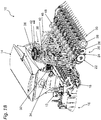
- a variant of an inventive distribution machine 10 is based on the two schematic perspective views of Figures 1A and 1B out.
- the Distributor initially has in the front region of a connecting device 12, by means of which the distributor 10 with a not shown here agricultural towing vehicle can be connected.
- a connecting device 12 In the connecting device according to the Figures 1A and 1B it is a three-point hitch.
- other appendages variants would also be conceivable, such as, for example, by means of drawbar eye or lower link suspension or any attachment or connecting device known from the agricultural sector.
- FIGS. 1 are below a reservoir 14, which serves to provide and to carry the Verteilguts, working tools 16 are arranged, wherein the working tools 16 in this case form a harrow.
- the working tools 16 in this case form a harrow.
- the distributor 10 has no working tools.
- the working tools 16 the area to be ordered or to be sowed is to be prepared and loosened accordingly, in order to thus improve the growth conditions for the plants or the material to be distributed. The loosened soil is then reconsolidated with a roller 18.
- coulters 20 which coulters are arranged with respect to the working width of the distributor 10 at regular intervals of, for example, 15 cm to each other.
- the illustrated coulters 20 are hereby designed as so-called double disc coulters. This means that they are constructed in such a way that a groove is produced in the bottom by means of two septum disks 22 arranged at an angle to one another, in which groove the distribution material is subsequently deposited by means of a seed tube 24 arranged between the two septum disks 22.
- the seed tube, a fishing reel 26 or a similar catch element may be arranged downstream.
- the furrow is closed by means of a pressure roller 28 or by means of a harrow 30.
- the pressure roller can also be used for depth control of the coulter 20 use here.
- the coulter 20 shown here as a double disc coulter represents only one possible embodiment of a coulter. In general, the use of a single-disc coulter or tine coulter or blade coulter or the like would be conceivable.
- Verteilgut is preferably volumetrically metered by a metering device located at the lower region in a desired amount.
- the distribution material is discharged into a line system 34, in which an air flow prevails, which is generated by an air conveying unit 36, such as a blower or the like.
- an air conveying unit 36 such as a blower or the like.
- the distributor tower 38 has at its upper end a distributor head 42, on the circumference of which a plurality of outlets 44 are arranged at regular intervals.
- a distributor head 42 In the distributor head 42 there is a distribution of a Verteilgutluftvolumenstroms in a plurality of Verteilgutluftvolumenströmen corresponding to the number of outlets 44.
- From the outlets 44 each carries a seed line 46 in the direction of the coulters 20 and in the direction of the coulters 20 respectively associated singulation 48. This is to note that in the FIG. 1B each of these seed lines 46 are not shown completely consistent for better understanding.
- Verteilgut is then at least largely isolated or largely homogenized by means of the singulation 48 and then passed through a seed coulter 20 associated seed tube 24 to the ground and stored in a seed furrow.
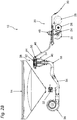
- FIGS. 2A to 2C show, with the FIGS. 2B and 2C represent the distributor 10 and their components in section.
- the cut corresponds to the Verteilgutl from the reservoir 14 to the distributor tower 38 via the outlet 44 in the direction of a coulter 20, in each case one row was shown in section here.
- Verteilgut is preferably volumetrically metered by a metering device located at the lower portion in a desired amount.
- the distribution material is discharged into a line system 34, in which an air flow prevails, which is generated by an air conveying unit 36 such as. A blower or the like.
- an air conveying unit 36 such as. A blower or the like.
- the distributor tower 38 has a distributor head 42 at its upper end. At its periphery are at regular intervals a plurality of outlets 44th arranged. In the distributor head 42 there is a distribution of the one Verteilgutluftvolumenstroms in a plurality of Verteilgutluftvolumenströmen, corresponding to the number of outlets 44. From the outlets 44 each leads a seed line 46 in the direction of the coulters 20 and in the direction of the coulters 20 respectively associated singulation 48th
- Verteilgut is then at least largely isolated or largely homogenized by means of the singulation 48 and then passed through a seed coulter 20 associated seed tube 24 to the ground and stored in a seed furrow.
- shut-off device 50 is arranged between the outlet 44 of the distributor head 42 and the separating device 48.
- This shut-off device is associated with a switch 52, by means of which the Verteilgutluftvolumenstrom can be directed either in the direction of a seed line 46 and thus in the direction of a coulter 20, or by means of which the Verteilgutluftvolumenstrom can be guided in a return area 54, via which return area 54 the Verteilgut then back in the direction of the distributor tower or the riser 40 is passed.
- a bypass 56 is integrated in the shut-off device 50.
- the return region 54 and the seed line 46 are permanently pneumatically connected, whereby at these positions largely the same pressure level prevails regardless of the respective position or position of the switch 52nd
- the distribution tower 38 consists essentially of a riser 40, at the upper end of a distributor head 42 connects. At the periphery of the distributor head 42, a plurality of outlets 44 or these downstream or in this integrated shut-off devices 50 are arranged at regular intervals.
- the distribution tower 38 initially has an arcuate transition piece 58, by means of which there is a reversal of direction of the Verteilgutluftvolumenstrom from a substantially horizontal in a vertical flow direction. Adjoining the transition piece 58 is a riser 40, which riser 40 initially has a nozzle section or a nozzle 60.
- the cross section of the riser 40 is conically reduced and then in turn conically enlarged.
- the Verteilgutluftvolumenstrom should be centered in the riser 40, whereby a subsequent uniform distribution of this is to be improved in the distributor head 42.
- other pipe sections 62 with cross-sectional tapering would also be conceivable, for example those in which only individual depressions are present. It would also be conceivable to replace the corrugated tube by a further nozzle 60, so that the riser 40 is composed of two nozzles or more.
- the individual sections of the riser 60 can each be connected by means of welding or by means of clamping pieces. Likewise, the sections may be made of a metallic or non-metallic material. Also, the riser 40 could be made in one piece and, for example. Plastic.
- a circular distributor head 42 adjoins, which has a flat cover 64.
- the Verteilgutluftvolumenstrom is deflected from a vertical in a horizontal direction, or in the direction of the outlets 44, for which purpose the Verteilgut example. May bounce against the lid 64 and then passed through the air flow in the direction of the outlets 44. The more uniform this distribution between the outlets 44, the more uniform is the transverse distribution of the Verteilguts on the agricultural machine
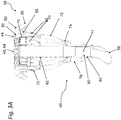
- each of the outlets 44 is a shut-off device 50 downstream.
- a pivotable switch 52 is attached.
- the switch 52 may, for example, by means of an electric and / or pneumatic and / or hydraulic and / or the like. Actuator between a closed position (see FIG. Fig. 3A right) and an open position (cf. Fig. 2C & Fig. 3A left).
- the blocking device 50 also has a return region 54, comprising a return connection 66 and a seed line connection 68 and a bypass 56.
- a claw 70 is first connected. This is formed in the exemplary embodiment y-shaped and connects two return ports 66 and two shut-off devices 28. To the claw 70, a return line 72 is also connected, which with its lower end via a nozzle 74 opens into a return device 76. With the help of the collecting pieces 70, the number of return lines 72 can be significantly reduced, in which case at least two but also more return lines 72 can be connected.
- the return device 76 is formed by a circular tube surrounding the nozzle 60 and the riser 40, respectively. Wherein the nozzle 60 in the region of its smallest diameter, a plurality of rectangular openings 78 are associated, which establish a connection between the riser 40 and the nozzle 60 and the return device 76.
- the arrangement of the openings 78 in the region of the nozzle 60 creates a suction at the openings, caused by the increased flow rate through the cross-sectional taper of the nozzle 60, whereby a Verteilgutgur arrangement from the return device 76 is further improved in the riser 40.
- the Verteilgutluftvolumenstrom is redirected in the shut-off device 50 in the direction of the return portion 54 and passed through the return port 66, the collecting pieces 70, the return line 72 and the return device 76 back into the riser 40.
- the recirculated Verteilgut is then again promoted by Verteilgutluftvolumenstrom in the riser 40 to the distributor head 42 and the outlets 44.
- the pressure levels or the air flows in the distributor head 42 are not affected or that the pressure P1 in the return device 76 or at the nozzle 74 is less than or equal the pressure P2 and P3 in the bypass 56 and 54 in the return area.
- the riser 40, the distributor head 42, the return device 76, the return region 54, the bypass 56 and the seed line connection 68 are permanently pneumatically connected, regardless of the position or the position of the switch 52. For example, located in the shut-off device 50, bypass 56 guaranteed.
- each of the metered by the metering device 32 in the line system Verteilgut be reduced accordingly, and this only from a certain number of closed outlets 44, for example, five outlets 44 may be required or is.
- the distribution tower 38 consists essentially of a riser 40, at the upper end of a distributor head 42 connects. At the periphery of the distributor head 42, a plurality of outlets 44 or these downstream shut-off devices 50 are arranged at regular intervals.
- the distribution tower 38 initially has an arcuate transition piece 58, by means of which there is a reversal of direction of the Verteilgut Kunststoffvolumenstroms from a substantially horizontal in a vertical flow direction. Adjoining the transition piece 58 is a riser 40, which riser 40 initially has a nozzle section or a nozzle 60.
- the cross section of the riser 40 is conically reduced and then in turn conically enlarged.
- the Verteilgutluftvolumenstrom should be centered in the riser 40, whereby a subsequent uniform distribution of this is to be improved in the distributor head 42.
- other pipe sections 62 with cross-sectional tapering would also be conceivable, for example those in which only individual depressions are present. It would also be conceivable to replace the corrugated tube by a further nozzle 60, so that the riser 40 is composed of two nozzles or more.
- the individual sections of the riser 60 can each be connected by means of welding or by means of clamping pieces. Likewise, the sections may be made of a metallic or non-metallic material. Also, the riser 40 could be made in one piece and, for example. Plastic.
- a circular distributor head 42 connects, which has a flat lid 64 and wherein this could also be mushroom-shaped.
- the Verteilgutluftvolumenstrom is deflected from a vertical in a horizontal direction, or in the direction of the outlets 44, for which purpose the Verteilgut example. May bounce against the lid 64 and then passed through the air flow in the direction of the outlets 44. The more uniform this distribution between the outlets 44, the more uniform is the transverse distribution of the Verteilguts on the agricultural machine.
- the pressure compensation device 80 shown in this embodiment could, in particular in conjunction with in the FIG. 3A
- Shut-off device 50 shown are combined so that, for example, at a distributor tower 38 only a small number of outlets 44 are provided with shut-off devices 50 and the rest each with pressure compensation devices 80.
Claims (12)
- Épandeur (10) pour matériau d'épandage de type granulé, notamment pour semences, engrais ou équivalent, composé au moins :- d'un réservoir de matériau (14) destiné à fournir le matériau d'épandage, ainsi que d'un dispositif de dosage (32) placé en aval de celui-ci, destiné au dosage du matériau d'épandage dans un débit volumique d'air créé à l'aide d'une unité de convoyage d'air (36), permettant de créer un débit volumique d'air de matériau d'épandage ;- une tour d'épandage (38) qui présente un tuyau montant (40) destiné à recevoir et à réacheminer le débit volumique d'air de matériau d'épandage, une tête d'épandage (42) étant rattachée au bout du tuyau montant (40), dans laquelle s'effectue un fractionnement dudit un débit volumique d'air de matériau d'épandage en une pluralité de débits volumiques d'air de matériau d'épandage en fonction d'un nombre de sorties (44) réparties sur sa circonférence ;- une pluralité de socs pour semoir (20) destinés au dépôt du matériau d'épandage, un dispositif d'individualisation (48), dans lequel débouche une conduite de semis (46), étant associé à chaque soc pour semoir (20), le matériau d'épandage convoyé par la conduite de semis (46) étant uniformisé ou individualisé au moyen du dispositif d'individualisation (48) ainsi que déposé sur le sol, ensuite, par le biais d'un tuyau de semis (24) associé au soc pour semoir (20),caractérisé en ce que, entre la sortie (44) de la tête d'épandage (42) et le dispositif d'individualisation (48) respectif, un dispositif d'arrêt (50) est agencé à chaque fois, le dispositif d'arrêt (50) présentant un séparateur (52) qui dirige le débit volumique d'air de matériau d'épandage en direction de la conduite de semis (46) ou en direction d'une zone de refoulement (54), un changement de position du séparateur (52) ayant lieu à l'aide d'un actionneur, de même que l'entraînement du dispositif d'individualisation (48) a lieu par entraînement motorisé, l'actionneur et l'entraînement motorisé étant respectivement actionnés en commun ou avec un décalage temporel défini l'un par rapport à l'autre.
- Épandeur (10) selon la revendication 1, caractérisé en ce que, à l'aide du dispositif de dosage (32), le matériau d'épandage est dosé en volume, dans une quantité définie, dans le débit volumétrique d'air.
- Épandeur (10) selon la revendication 1 ou 2, caractérisé en ce que le dispositif d'arrêt (50) présente une première zone destinée au réacheminement du matériau d'épandage en direction de la conduite de semis (46), ainsi qu'une deuxième zone destinée au réacheminement du matériau d'épandage en direction de la zone de refoulement (54), du tuyau montant (40), du réservoir de matériau (14) ou du système de conduite (34), et qu'il présente une troisième zone, ladite troisième zone constitue une dérivation (56) par laquelle les première et deuxième zones sont reliées de manière durablement pneumatique, ce qui permet d'établir dans celles-ci un niveau de pression respectif sensiblement homogène.
- Épandeur (10) selon la revendication 3, caractérisé en ce qu'un niveau de pression (P1) dans un dispositif de refoulement (76) est inférieur ou égal à un niveau de pression (P2 et P3) qui règne dans la dérivation (56) et dans la zone de refoulement (54).
- Épandeur (10) selon l'une quelconque des revendications 1 à 4 précédentes, caractérisé en ce qu'un dispositif de pressurisation (80) est agencé au moins entre une sortie (44) et un dispositif d'individualisation (48).
- Épandeur (10) selon l'une quelconque des revendications 1 à 4 précédentes, caractérisé en ce qu'il y a un même nombre de sorties (44), de dispositifs d'arrêt (50), de dispositifs d'individualisation (48) et de socs pour semoir (20).
- Épandeur (10) selon l'une quelconque des revendications 1 à 6 précédentes, caractérisé en ce que l'actionnement de l'actionneur et/ou de l'entraînement motorisé s'effectue sur la base de la position de l'épandeur (10).
- Épandeur (10) selon l'une quelconque des revendications 1 à 7 précédentes, caractérisé en ce que le soc pour semoir (20) est constitué en tant que soc à double disque ou en tant que soc mono-disque ou en tant que soc-fourche ou en tant que soc à patin.
- Procédé d'épandage de matériau d'épandage de type granulés, tel que semences, engrais ou équivalent, le procédé comprenant :- la fourniture du matériau d'épandage au moyen d'un réservoir de matériau (14) ainsi qu'un dosage du matériau d'épandage au moyen d'un dispositif de dosage (32) agencé en aval du réservoir de matériau (14) dans un débit volumique d'air créé par une unité de convoyage d'air (36), ce qui permet de créer un débit volumique d'air de matériau d'épandage ;- acheminement du débit volumique d'air de matériau d'épandage dans une tour d'épandage (38) qui présente un tuyau montant (40) destiné à recevoir et à réacheminer le débit volumique d'air de matériau d'épandage, et une tête d'épandage (42) étant rattachée au bout du tuyau montant (40), dans laquelle s'effectue un fractionnement dudit un débit volumique d'air de matériau d'épandage en une pluralité de débits volumiques d'air de matériau d'épandage en fonction d'un nombre de sorties (44) réparties sur sa circonférence ;- dépôt du matériau d'épandage au moyen d'une pluralité de socs pour semoir (20), un dispositif d'individualisation (48), dans lequel débouche une conduite de semis (46), étant associé à chaque soc pour semoir (20), le matériau d'épandage convoyé par la conduite de semis (46) étant uniformisé ou individualisé au moyen du dispositif d'individualisation (48) ainsi que déposé sur le sol, ensuite, par le biais d'un tuyau de semis (24) associé au soc pour semoir (20),caractérisé en ce qu'un dispositif d'arrêt (50) est agencé entre la sortie (44) de la tête d'épandage (42) et le dispositif d'individualisation (48), le dispositif d'arrêt (50) présentant un séparateur (52) qui dirige le débit volumique d'air de matériau d'épandage au choix en direction de la conduite de semis (46) ou en direction d'une zone de refoulement (54), un changement de position du séparateur (52) s'effectuant à l'aide d'un actionneur, de même que l'entraînement du dispositif d'individualisation (48) s'effectue par un entraînement motorisé, l'actionneur et l'entraînement motorisé étant respectivement actionnés ensemble ou avec un décalage temporel, défini, l'un par rapport à l'autre.
- Procédé selon la revendication 9, caractérisé en ce que, à l'aide du dispositif de dosage (32), une quantité dosée en volume de matériau d'épandage est envoyée dans le débit volumétrique d'air.
- Procédé selon la revendication 9 ou 10, caractérisé en ce que le dispositif d'arrêt (50) présente une première zone destinée au réacheminement du matériau d'épandage en direction de la conduite de semis (46), ainsi qu'une deuxième zone destinée au réacheminement du matériau d'épandage en direction de la zone de refoulement (54), du tuyau montant (40), du réservoir de matériau (14) ou du système de conduite (34), et qu'il présente une troisième zone, ladite troisième zone constituant une dérivation (56) par laquelle les première et deuxième zones sont reliées de manière durablement pneumatique, ce qui permet d'établir dans celles-ci un niveau de pression respectif sensiblement homogène.
- Procédé selon l'une quelconque des revendications 9 à 11, caractérisé en ce que l'actionnement de l'actionneur et/ou de l'entraînement motorisé s'effectue sur la base de la position de l'épandeur (10).
Applications Claiming Priority (1)
| Application Number | Priority Date | Filing Date | Title |
|---|---|---|---|
| DE102016115236.6A DE102016115236A1 (de) | 2016-08-17 | 2016-08-17 | Verteilmaschine und Verfahren zur Aussaat von granulatartigem Verteilgut |
Publications (2)
| Publication Number | Publication Date |
|---|---|
| EP3284332A1 EP3284332A1 (fr) | 2018-02-21 |
| EP3284332B1 true EP3284332B1 (fr) | 2019-10-16 |
Family
ID=59522983
Family Applications (1)
| Application Number | Title | Priority Date | Filing Date |
|---|---|---|---|
| EP17184658.7A Active EP3284332B1 (fr) | 2016-08-17 | 2017-08-03 | Machine de distribution et procédé d'ensemencement de produit granulaire |
Country Status (2)
| Country | Link |
|---|---|
| EP (1) | EP3284332B1 (fr) |
| DE (1) | DE102016115236A1 (fr) |
Cited By (11)
| Publication number | Priority date | Publication date | Assignee | Title |
|---|---|---|---|---|
| US11483963B2 (en) | 2019-12-24 | 2022-11-01 | Cnh Industrial America Llc | Particle delivery system of an agricultural row unit |
| US11490558B2 (en) | 2019-12-24 | 2022-11-08 | Cnh Industrial America Llc | Particle delivery system of an agricultural row unit |
| US11516958B2 (en) | 2019-12-24 | 2022-12-06 | Cnh Industrial America Llc | Particle delivery system of an agricultural row unit |
| US11523555B2 (en) | 2019-12-24 | 2022-12-13 | Cnh Industrial America Llc | Particle delivery system of an agricultural row unit |
| US11523556B2 (en) | 2019-12-24 | 2022-12-13 | Cnh Industrial America Llc | Particle delivery system of an agricultural row unit |
| US11553639B2 (en) | 2019-12-24 | 2023-01-17 | Cnh Industrial America Llc | Particle delivery system of an agricultural row unit |
| US11564346B2 (en) | 2019-12-24 | 2023-01-31 | Cnh Industrial America Llc | Particle delivery system of an agricultural row unit |
| US11564344B2 (en) | 2019-12-24 | 2023-01-31 | Cnh Industrial America Llc | Particle delivery system of an agricultural row unit |
| US11582899B2 (en) | 2019-12-24 | 2023-02-21 | Cnh Industrial America Llc | Particle delivery system of an agricultural row unit |
| US11589500B2 (en) | 2019-12-24 | 2023-02-28 | Cnh Industrial America Llc | Particle delivery system of an agricultural row unit |
| US11596095B2 (en) | 2019-12-24 | 2023-03-07 | Cnh Industrial America Llc | Particle delivery system of an agricultural row unit |
Families Citing this family (9)
| Publication number | Priority date | Publication date | Assignee | Title |
|---|---|---|---|---|
| DE102017203857A1 (de) * | 2017-03-08 | 2018-09-13 | Horsch Maschinen Gmbh | Verteilerturm einer landwirtschaftlichen Maschine, landwirtschaftliche Maschine und Verfahren zum Betreiben einer solchen landwirtschaftlichen Maschine |
| DE102017203855A1 (de) * | 2017-03-08 | 2018-09-13 | Horsch Maschinen Gmbh | Verteilerturm einer landwirtschaftlichen Maschine, landwirtschaftliche Maschine und Verfahren zum Betreiben einer solchen landwirtschaftlichen Maschine |
| CN109362292A (zh) * | 2018-11-09 | 2019-02-22 | 中国农业机械化科学研究院 | 一种气流输送式苔麸播种机 |
| DE102018130717A1 (de) | 2018-12-03 | 2020-06-04 | Horsch Maschinen Gmbh | Landwirtschaftliche Verteilmaschine und Verfahren zum Ausbringen von granularem Verteilgut |
| AT521353B1 (de) * | 2019-01-22 | 2020-01-15 | Wintersteiger Ag | Einzelkornsämaschine |
| DE102020133366A1 (de) | 2020-12-14 | 2022-06-15 | Horsch Maschinen Gmbh | Landwirtschaftliche Verteilanordnung mit heckseitiger Verteilvorrichtung und frontseitiger Tankkonstruktion |
| CN113316999A (zh) * | 2021-07-13 | 2021-08-31 | 南京磊婧中药材种植有限公司 | 一种苍术自动种植装置 |
| DE102021127899A1 (de) | 2021-10-27 | 2023-04-27 | Amazonen-Werke H. Dreyer SE & Co. KG | Stromlos betreibbare Konditioniervorrichtung für ein pneumatisches Fördersystem einer landwirtschaftlichen Ausbringmaschine |
| DE102022103592A1 (de) | 2022-02-16 | 2023-08-17 | Horsch Maschinen Gmbh | Verteilmaschine |
Family Cites Families (9)
| Publication number | Priority date | Publication date | Assignee | Title |
|---|---|---|---|---|
| DE19613785C2 (de) * | 1996-04-04 | 2002-08-22 | Kverneland Accord Gmbh & Co Kg | Abluftleitung für eine pneumatisch arbeitende Verteilmaschine |
| CA2635401C (fr) * | 2007-09-21 | 2009-11-24 | One Pass Implements Inc. | Appareil fertilisateur/semoir pneumatique comprenant des dispositifs de mesure et un collecteur de distribution avec des orifices ouvrables de maniere selective |
| DE102011018447A1 (de) | 2011-04-21 | 2012-10-25 | Alois Pöttinger Maschinenfabrik Gmbh | Reihensämaschine |
| DE102012105048A1 (de) | 2012-06-12 | 2013-12-12 | Horsch Maschinen Gmbh | Verteilaggregat für körniges Gut, insbesondere Säaggregat |
| DE102012015731A1 (de) * | 2012-08-09 | 2014-02-13 | Alois Pöttinger Maschinenfabrik Ges.m.b.H. | Verteilerkopf für eine Sä- und/oder Düngemaschine |
| DE102013008868A1 (de) | 2013-05-24 | 2014-11-27 | Alois Pöttinger Maschinenfabrik Ges.m.b.H. | Sämaschine |
| DE102013215186A1 (de) * | 2013-08-01 | 2015-02-05 | Horsch Maschinen Gmbh | Verfahren zur Dosierung von körnigem Gut und Dosiervorrichtung für körniges Gut |
| EP2932818B1 (fr) | 2014-04-16 | 2018-08-01 | Horsch Maschinen GmbH | Dispositif d'épandage et procédé d'épandage de produit granulaire |
| DE102015116378A1 (de) | 2015-09-28 | 2017-03-30 | Horsch Maschinen Gmbh | Verteilturm einer landwirtschaftlichen Verteilmaschine |
-
2016
- 2016-08-17 DE DE102016115236.6A patent/DE102016115236A1/de active Pending
-
2017
- 2017-08-03 EP EP17184658.7A patent/EP3284332B1/fr active Active
Non-Patent Citations (1)
| Title |
|---|
| None * |
Cited By (11)
| Publication number | Priority date | Publication date | Assignee | Title |
|---|---|---|---|---|
| US11483963B2 (en) | 2019-12-24 | 2022-11-01 | Cnh Industrial America Llc | Particle delivery system of an agricultural row unit |
| US11490558B2 (en) | 2019-12-24 | 2022-11-08 | Cnh Industrial America Llc | Particle delivery system of an agricultural row unit |
| US11516958B2 (en) | 2019-12-24 | 2022-12-06 | Cnh Industrial America Llc | Particle delivery system of an agricultural row unit |
| US11523555B2 (en) | 2019-12-24 | 2022-12-13 | Cnh Industrial America Llc | Particle delivery system of an agricultural row unit |
| US11523556B2 (en) | 2019-12-24 | 2022-12-13 | Cnh Industrial America Llc | Particle delivery system of an agricultural row unit |
| US11553639B2 (en) | 2019-12-24 | 2023-01-17 | Cnh Industrial America Llc | Particle delivery system of an agricultural row unit |
| US11564346B2 (en) | 2019-12-24 | 2023-01-31 | Cnh Industrial America Llc | Particle delivery system of an agricultural row unit |
| US11564344B2 (en) | 2019-12-24 | 2023-01-31 | Cnh Industrial America Llc | Particle delivery system of an agricultural row unit |
| US11582899B2 (en) | 2019-12-24 | 2023-02-21 | Cnh Industrial America Llc | Particle delivery system of an agricultural row unit |
| US11589500B2 (en) | 2019-12-24 | 2023-02-28 | Cnh Industrial America Llc | Particle delivery system of an agricultural row unit |
| US11596095B2 (en) | 2019-12-24 | 2023-03-07 | Cnh Industrial America Llc | Particle delivery system of an agricultural row unit |
Also Published As
| Publication number | Publication date |
|---|---|
| DE102016115236A1 (de) | 2018-02-22 |
| EP3284332A1 (fr) | 2018-02-21 |
Similar Documents
| Publication | Publication Date | Title |
|---|---|---|
| EP3284332B1 (fr) | Machine de distribution et procédé d'ensemencement de produit granulaire | |
| EP3355673B1 (fr) | Tête de distribution pour machine de distribution agricole et procédé de désactivation des rangs d'une telle tête de distribution | |
| EP3501250B1 (fr) | Épandeur agricole et procédé de commande de rangée simple et groupée d'un tel épandeur agricole | |
| EP3372065B1 (fr) | Tour de distribution d'une machine agricole, machine agricole et procédé de fonctionnement d'une telle machine agricole | |
| EP2932818B1 (fr) | Dispositif d'épandage et procédé d'épandage de produit granulaire | |
| DE69616283T3 (de) | Pflanzeinheit | |
| EP2774466B1 (fr) | Semoir | |
| EP3065529B1 (fr) | Semoir | |
| EP2695508B1 (fr) | Tête de répartition pour une machine à semence ou à engrais | |
| EP3788855A1 (fr) | Semoir monograine agricole et procédé | |
| EP2805594B1 (fr) | Semoir | |
| DE102011054862A1 (de) | Bodenbearbeitungsgerät und Verfahren zur Einbringung von wasserspeicherndem Material und/oder Düngemittel und/oder Saatgut in den Erdboden | |
| EP3417688A1 (fr) | Machine d'épandage pneumatique agricole | |
| DD297298A5 (de) | Vorrichtung zum einbringen von samen in den boden | |
| DE112004001272B4 (de) | Vorrichtung an einem Verteilerkopf | |
| WO2021083536A1 (fr) | Machine d'épandage pneumatique | |
| WO2019030309A1 (fr) | Soc de semoir et semoir | |
| DE2851797A1 (de) | Maschine zum ausstreuen von koernigem material | |
| WO2009129982A1 (fr) | Semoir direct pneumatique | |
| DE102009012849A1 (de) | Pneumatische Direktsämaschine | |
| EP4305943A1 (fr) | Dispositif de transport pneumatique d'un agent auxiliaire vers des unités en série d'un semoir | |
| WO2023186553A1 (fr) | Unité d'ensemencement pour semoir monograine | |
| DE3819121A1 (de) | Vorrichtung zum duengen einer reihenkultur | |
| EP4230019A1 (fr) | Epandeur pneumatique d'engrais | |
| EP4316231A1 (fr) | Dispositif de soc et machine de travail agricole dotée d'une pluralité de tels dispositifs de soc |
Legal Events
| Date | Code | Title | Description |
|---|---|---|---|
| PUAI | Public reference made under article 153(3) epc to a published international application that has entered the european phase |
Free format text: ORIGINAL CODE: 0009012 |
|
| STAA | Information on the status of an ep patent application or granted ep patent |
Free format text: STATUS: THE APPLICATION HAS BEEN PUBLISHED |
|
| AK | Designated contracting states |
Kind code of ref document: A1 Designated state(s): AL AT BE BG CH CY CZ DE DK EE ES FI FR GB GR HR HU IE IS IT LI LT LU LV MC MK MT NL NO PL PT RO RS SE SI SK SM TR |
|
| AX | Request for extension of the european patent |
Extension state: BA ME |
|
| STAA | Information on the status of an ep patent application or granted ep patent |
Free format text: STATUS: REQUEST FOR EXAMINATION WAS MADE |
|
| 17P | Request for examination filed |
Effective date: 20180516 |
|
| RBV | Designated contracting states (corrected) |
Designated state(s): AL AT BE BG CH CY CZ DE DK EE ES FI FR GB GR HR HU IE IS IT LI LT LU LV MC MK MT NL NO PL PT RO RS SE SI SK SM TR |
|
| GRAP | Despatch of communication of intention to grant a patent |
Free format text: ORIGINAL CODE: EPIDOSNIGR1 |
|
| STAA | Information on the status of an ep patent application or granted ep patent |
Free format text: STATUS: GRANT OF PATENT IS INTENDED |
|
| RIC1 | Information provided on ipc code assigned before grant |
Ipc: A01C 7/08 20060101AFI20190502BHEP Ipc: A01C 7/04 20060101ALN20190502BHEP |
|
| INTG | Intention to grant announced |
Effective date: 20190522 |
|
| GRAS | Grant fee paid |
Free format text: ORIGINAL CODE: EPIDOSNIGR3 |
|
| GRAA | (expected) grant |
Free format text: ORIGINAL CODE: 0009210 |
|
| STAA | Information on the status of an ep patent application or granted ep patent |
Free format text: STATUS: THE PATENT HAS BEEN GRANTED |
|
| AK | Designated contracting states |
Kind code of ref document: B1 Designated state(s): AL AT BE BG CH CY CZ DE DK EE ES FI FR GB GR HR HU IE IS IT LI LT LU LV MC MK MT NL NO PL PT RO RS SE SI SK SM TR |
|
| REG | Reference to a national code |
Ref country code: GB Ref legal event code: FG4D Free format text: NOT ENGLISH |
|
| REG | Reference to a national code |
Ref country code: CH Ref legal event code: EP |
|
| REG | Reference to a national code |
Ref country code: DE Ref legal event code: R096 Ref document number: 502017002574 Country of ref document: DE |
|
| REG | Reference to a national code |
Ref country code: IE Ref legal event code: FG4D Free format text: LANGUAGE OF EP DOCUMENT: GERMAN |
|
| REG | Reference to a national code |
Ref country code: AT Ref legal event code: REF Ref document number: 1190377 Country of ref document: AT Kind code of ref document: T Effective date: 20191115 |
|
| REG | Reference to a national code |
Ref country code: NL Ref legal event code: MP Effective date: 20191016 |
|
| REG | Reference to a national code |
Ref country code: LT Ref legal event code: MG4D |
|
| PG25 | Lapsed in a contracting state [announced via postgrant information from national office to epo] |
Ref country code: FI Free format text: LAPSE BECAUSE OF FAILURE TO SUBMIT A TRANSLATION OF THE DESCRIPTION OR TO PAY THE FEE WITHIN THE PRESCRIBED TIME-LIMIT Effective date: 20191016 Ref country code: BG Free format text: LAPSE BECAUSE OF FAILURE TO SUBMIT A TRANSLATION OF THE DESCRIPTION OR TO PAY THE FEE WITHIN THE PRESCRIBED TIME-LIMIT Effective date: 20200116 Ref country code: GR Free format text: LAPSE BECAUSE OF FAILURE TO SUBMIT A TRANSLATION OF THE DESCRIPTION OR TO PAY THE FEE WITHIN THE PRESCRIBED TIME-LIMIT Effective date: 20200117 Ref country code: NO Free format text: LAPSE BECAUSE OF FAILURE TO SUBMIT A TRANSLATION OF THE DESCRIPTION OR TO PAY THE FEE WITHIN THE PRESCRIBED TIME-LIMIT Effective date: 20200116 Ref country code: PT Free format text: LAPSE BECAUSE OF FAILURE TO SUBMIT A TRANSLATION OF THE DESCRIPTION OR TO PAY THE FEE WITHIN THE PRESCRIBED TIME-LIMIT Effective date: 20200217 Ref country code: LT Free format text: LAPSE BECAUSE OF FAILURE TO SUBMIT A TRANSLATION OF THE DESCRIPTION OR TO PAY THE FEE WITHIN THE PRESCRIBED TIME-LIMIT Effective date: 20191016 Ref country code: SE Free format text: LAPSE BECAUSE OF FAILURE TO SUBMIT A TRANSLATION OF THE DESCRIPTION OR TO PAY THE FEE WITHIN THE PRESCRIBED TIME-LIMIT Effective date: 20191016 Ref country code: PL Free format text: LAPSE BECAUSE OF FAILURE TO SUBMIT A TRANSLATION OF THE DESCRIPTION OR TO PAY THE FEE WITHIN THE PRESCRIBED TIME-LIMIT Effective date: 20191016 Ref country code: LV Free format text: LAPSE BECAUSE OF FAILURE TO SUBMIT A TRANSLATION OF THE DESCRIPTION OR TO PAY THE FEE WITHIN THE PRESCRIBED TIME-LIMIT Effective date: 20191016 Ref country code: NL Free format text: LAPSE BECAUSE OF FAILURE TO SUBMIT A TRANSLATION OF THE DESCRIPTION OR TO PAY THE FEE WITHIN THE PRESCRIBED TIME-LIMIT Effective date: 20191016 |
|
| PG25 | Lapsed in a contracting state [announced via postgrant information from national office to epo] |
Ref country code: IS Free format text: LAPSE BECAUSE OF FAILURE TO SUBMIT A TRANSLATION OF THE DESCRIPTION OR TO PAY THE FEE WITHIN THE PRESCRIBED TIME-LIMIT Effective date: 20200224 Ref country code: HR Free format text: LAPSE BECAUSE OF FAILURE TO SUBMIT A TRANSLATION OF THE DESCRIPTION OR TO PAY THE FEE WITHIN THE PRESCRIBED TIME-LIMIT Effective date: 20191016 Ref country code: RS Free format text: LAPSE BECAUSE OF FAILURE TO SUBMIT A TRANSLATION OF THE DESCRIPTION OR TO PAY THE FEE WITHIN THE PRESCRIBED TIME-LIMIT Effective date: 20191016 |
|
| PG25 | Lapsed in a contracting state [announced via postgrant information from national office to epo] |
Ref country code: AL Free format text: LAPSE BECAUSE OF FAILURE TO SUBMIT A TRANSLATION OF THE DESCRIPTION OR TO PAY THE FEE WITHIN THE PRESCRIBED TIME-LIMIT Effective date: 20191016 |
|
| REG | Reference to a national code |
Ref country code: DE Ref legal event code: R097 Ref document number: 502017002574 Country of ref document: DE |
|
| PG2D | Information on lapse in contracting state deleted |
Ref country code: IS |
|
| PG25 | Lapsed in a contracting state [announced via postgrant information from national office to epo] |
Ref country code: ES Free format text: LAPSE BECAUSE OF FAILURE TO SUBMIT A TRANSLATION OF THE DESCRIPTION OR TO PAY THE FEE WITHIN THE PRESCRIBED TIME-LIMIT Effective date: 20191016 Ref country code: DK Free format text: LAPSE BECAUSE OF FAILURE TO SUBMIT A TRANSLATION OF THE DESCRIPTION OR TO PAY THE FEE WITHIN THE PRESCRIBED TIME-LIMIT Effective date: 20191016 Ref country code: EE Free format text: LAPSE BECAUSE OF FAILURE TO SUBMIT A TRANSLATION OF THE DESCRIPTION OR TO PAY THE FEE WITHIN THE PRESCRIBED TIME-LIMIT Effective date: 20191016 Ref country code: RO Free format text: LAPSE BECAUSE OF FAILURE TO SUBMIT A TRANSLATION OF THE DESCRIPTION OR TO PAY THE FEE WITHIN THE PRESCRIBED TIME-LIMIT Effective date: 20191016 Ref country code: CZ Free format text: LAPSE BECAUSE OF FAILURE TO SUBMIT A TRANSLATION OF THE DESCRIPTION OR TO PAY THE FEE WITHIN THE PRESCRIBED TIME-LIMIT Effective date: 20191016 Ref country code: IS Free format text: LAPSE BECAUSE OF FAILURE TO SUBMIT A TRANSLATION OF THE DESCRIPTION OR TO PAY THE FEE WITHIN THE PRESCRIBED TIME-LIMIT Effective date: 20200216 |
|
| PLBE | No opposition filed within time limit |
Free format text: ORIGINAL CODE: 0009261 |
|
| STAA | Information on the status of an ep patent application or granted ep patent |
Free format text: STATUS: NO OPPOSITION FILED WITHIN TIME LIMIT |
|
| PG25 | Lapsed in a contracting state [announced via postgrant information from national office to epo] |
Ref country code: IT Free format text: LAPSE BECAUSE OF FAILURE TO SUBMIT A TRANSLATION OF THE DESCRIPTION OR TO PAY THE FEE WITHIN THE PRESCRIBED TIME-LIMIT Effective date: 20191016 Ref country code: SM Free format text: LAPSE BECAUSE OF FAILURE TO SUBMIT A TRANSLATION OF THE DESCRIPTION OR TO PAY THE FEE WITHIN THE PRESCRIBED TIME-LIMIT Effective date: 20191016 Ref country code: SK Free format text: LAPSE BECAUSE OF FAILURE TO SUBMIT A TRANSLATION OF THE DESCRIPTION OR TO PAY THE FEE WITHIN THE PRESCRIBED TIME-LIMIT Effective date: 20191016 |
|
| 26N | No opposition filed |
Effective date: 20200717 |
|
| PG25 | Lapsed in a contracting state [announced via postgrant information from national office to epo] |
Ref country code: SI Free format text: LAPSE BECAUSE OF FAILURE TO SUBMIT A TRANSLATION OF THE DESCRIPTION OR TO PAY THE FEE WITHIN THE PRESCRIBED TIME-LIMIT Effective date: 20191016 |
|
| PG25 | Lapsed in a contracting state [announced via postgrant information from national office to epo] |
Ref country code: MC Free format text: LAPSE BECAUSE OF FAILURE TO SUBMIT A TRANSLATION OF THE DESCRIPTION OR TO PAY THE FEE WITHIN THE PRESCRIBED TIME-LIMIT Effective date: 20191016 |
|
| REG | Reference to a national code |
Ref country code: CH Ref legal event code: PL |
|
| PG25 | Lapsed in a contracting state [announced via postgrant information from national office to epo] |
Ref country code: LU Free format text: LAPSE BECAUSE OF NON-PAYMENT OF DUE FEES Effective date: 20200803 Ref country code: LI Free format text: LAPSE BECAUSE OF NON-PAYMENT OF DUE FEES Effective date: 20200831 Ref country code: CH Free format text: LAPSE BECAUSE OF NON-PAYMENT OF DUE FEES Effective date: 20200831 |
|
| REG | Reference to a national code |
Ref country code: BE Ref legal event code: MM Effective date: 20200831 |
|
| PG25 | Lapsed in a contracting state [announced via postgrant information from national office to epo] |
Ref country code: FR Free format text: LAPSE BECAUSE OF NON-PAYMENT OF DUE FEES Effective date: 20200831 |
|
| PG25 | Lapsed in a contracting state [announced via postgrant information from national office to epo] |
Ref country code: IE Free format text: LAPSE BECAUSE OF NON-PAYMENT OF DUE FEES Effective date: 20200803 Ref country code: BE Free format text: LAPSE BECAUSE OF NON-PAYMENT OF DUE FEES Effective date: 20200831 |
|
| GBPC | Gb: european patent ceased through non-payment of renewal fee |
Effective date: 20210803 |
|
| PG25 | Lapsed in a contracting state [announced via postgrant information from national office to epo] |
Ref country code: TR Free format text: LAPSE BECAUSE OF FAILURE TO SUBMIT A TRANSLATION OF THE DESCRIPTION OR TO PAY THE FEE WITHIN THE PRESCRIBED TIME-LIMIT Effective date: 20191016 Ref country code: MT Free format text: LAPSE BECAUSE OF FAILURE TO SUBMIT A TRANSLATION OF THE DESCRIPTION OR TO PAY THE FEE WITHIN THE PRESCRIBED TIME-LIMIT Effective date: 20191016 Ref country code: CY Free format text: LAPSE BECAUSE OF FAILURE TO SUBMIT A TRANSLATION OF THE DESCRIPTION OR TO PAY THE FEE WITHIN THE PRESCRIBED TIME-LIMIT Effective date: 20191016 |
|
| PG25 | Lapsed in a contracting state [announced via postgrant information from national office to epo] |
Ref country code: MK Free format text: LAPSE BECAUSE OF FAILURE TO SUBMIT A TRANSLATION OF THE DESCRIPTION OR TO PAY THE FEE WITHIN THE PRESCRIBED TIME-LIMIT Effective date: 20191016 |
|
| PG25 | Lapsed in a contracting state [announced via postgrant information from national office to epo] |
Ref country code: GB Free format text: LAPSE BECAUSE OF NON-PAYMENT OF DUE FEES Effective date: 20210803 |
|
| REG | Reference to a national code |
Ref country code: AT Ref legal event code: MM01 Ref document number: 1190377 Country of ref document: AT Kind code of ref document: T Effective date: 20220803 |
|
| PG25 | Lapsed in a contracting state [announced via postgrant information from national office to epo] |
Ref country code: AT Free format text: LAPSE BECAUSE OF NON-PAYMENT OF DUE FEES Effective date: 20220803 |
|
| PGFP | Annual fee paid to national office [announced via postgrant information from national office to epo] |
Ref country code: DE Payment date: 20230822 Year of fee payment: 7 |