EP3284332B1 - Distribution machine and method for sowing of granular material - Google Patents
Distribution machine and method for sowing of granular material Download PDFInfo
- Publication number
- EP3284332B1 EP3284332B1 EP17184658.7A EP17184658A EP3284332B1 EP 3284332 B1 EP3284332 B1 EP 3284332B1 EP 17184658 A EP17184658 A EP 17184658A EP 3284332 B1 EP3284332 B1 EP 3284332B1
- Authority
- EP
- European Patent Office
- Prior art keywords
- distribution
- air volume
- goods
- distribution goods
- volume flow
- Prior art date
- Legal status (The legal status is an assumption and is not a legal conclusion. Google has not performed a legal analysis and makes no representation as to the accuracy of the status listed.)
- Active
Links
- 238000009826 distribution Methods 0.000 title claims description 124
- 238000000034 method Methods 0.000 title claims description 17
- 238000009331 sowing Methods 0.000 title claims description 15
- 239000008187 granular material Substances 0.000 title description 7
- 238000003860 storage Methods 0.000 claims description 10
- 230000008859 change Effects 0.000 claims description 4
- 235000013339 cereals Nutrition 0.000 description 33
- 239000000463 material Substances 0.000 description 18
- 238000000926 separation method Methods 0.000 description 13
- 241000196324 Embryophyta Species 0.000 description 7
- 210000000078 claw Anatomy 0.000 description 5
- 230000007704 transition Effects 0.000 description 5
- 230000008901 benefit Effects 0.000 description 4
- 238000013461 design Methods 0.000 description 4
- 241000209140 Triticum Species 0.000 description 3
- 235000021307 Triticum Nutrition 0.000 description 3
- 239000003337 fertilizer Substances 0.000 description 3
- -1 seed Substances 0.000 description 3
- 238000009827 uniform distribution Methods 0.000 description 3
- 240000008042 Zea mays Species 0.000 description 2
- 235000005824 Zea mays ssp. parviglumis Nutrition 0.000 description 2
- 235000002017 Zea mays subsp mays Nutrition 0.000 description 2
- 235000005822 corn Nutrition 0.000 description 2
- 230000006872 improvement Effects 0.000 description 2
- 239000007769 metal material Substances 0.000 description 2
- 239000002689 soil Substances 0.000 description 2
- 238000003466 welding Methods 0.000 description 2
- 206010010774 Constipation Diseases 0.000 description 1
- 244000068988 Glycine max Species 0.000 description 1
- 235000010469 Glycine max Nutrition 0.000 description 1
- 230000009471 action Effects 0.000 description 1
- 230000004913 activation Effects 0.000 description 1
- 230000006978 adaptation Effects 0.000 description 1
- 230000002411 adverse Effects 0.000 description 1
- 238000013459 approach Methods 0.000 description 1
- 230000000903 blocking effect Effects 0.000 description 1
- 238000010276 construction Methods 0.000 description 1
- 230000009849 deactivation Effects 0.000 description 1
- 230000001419 dependent effect Effects 0.000 description 1
- 238000011161 development Methods 0.000 description 1
- 230000018109 developmental process Effects 0.000 description 1
- 230000000694 effects Effects 0.000 description 1
- 238000009313 farming Methods 0.000 description 1
- 238000012986 modification Methods 0.000 description 1
- 230000004048 modification Effects 0.000 description 1
- 239000000725 suspension Substances 0.000 description 1
Images


Classifications
-
- A—HUMAN NECESSITIES
- A01—AGRICULTURE; FORESTRY; ANIMAL HUSBANDRY; HUNTING; TRAPPING; FISHING
- A01C—PLANTING; SOWING; FERTILISING
- A01C7/00—Sowing
- A01C7/08—Broadcast seeders; Seeders depositing seeds in rows
- A01C7/081—Seeders depositing seeds in rows using pneumatic means
- A01C7/084—Pneumatic distribution heads for seeders
-
- A—HUMAN NECESSITIES
- A01—AGRICULTURE; FORESTRY; ANIMAL HUSBANDRY; HUNTING; TRAPPING; FISHING
- A01C—PLANTING; SOWING; FERTILISING
- A01C7/00—Sowing
- A01C7/08—Broadcast seeders; Seeders depositing seeds in rows
- A01C7/088—Sectional seeding
-
- A—HUMAN NECESSITIES
- A01—AGRICULTURE; FORESTRY; ANIMAL HUSBANDRY; HUNTING; TRAPPING; FISHING
- A01C—PLANTING; SOWING; FERTILISING
- A01C7/00—Sowing
- A01C7/04—Single-grain seeders with or without suction devices
-
- A—HUMAN NECESSITIES
- A01—AGRICULTURE; FORESTRY; ANIMAL HUSBANDRY; HUNTING; TRAPPING; FISHING
- A01C—PLANTING; SOWING; FERTILISING
- A01C7/00—Sowing
- A01C7/08—Broadcast seeders; Seeders depositing seeds in rows
- A01C7/081—Seeders depositing seeds in rows using pneumatic means
Definitions
- the present invention relates to a distribution machine for granular distribution material with the features of independent claim 1.
- the invention also relates to a method for sowing granular distribution material with the features of independent method claim 9.
- Distribution machines are used in agriculture for the distribution of granular or granular material such as seed, fertilizer or the like.
- the distribution is usually in each case in defined row spacing by means of different coulters.
- the distribution should in each case be such that each share is approximately supplied with the same amount of Verteilgut, regardless of the working width of the machine.
- the distribution in the longitudinal direction or in the direction of travel of the distributor should be such that in each case as far as possible a single grain is deposited.
- transverse distribution and longitudinal distribution the so-called plant standing space depends on the plant, i. how much space the particular plant has on a field in order to develop accordingly, again, the more even the stand space the more even the plant stock.
- the distribution machines can generally be divided into three main categories; namely in mechanically or pneumatically operated seed drills as well as in precision seed drills, whereby in turn each of these types of machines is preferably used for a special sowing method.
- Mechanically and pneumatically operated distribution machines are used in particular for drilled sowing, while the precision seed drills are used in particular for isolated or uniformed single-seed sowing.
- precision seeders By means of known from the prior art precision seeders is a scattered or gleichrichte grain delivery of the Verteilguts in the row with partially large row spacing of the coulters to each other; This row spacing across the direction of travel can be, for example, 45cm or 70cm or 80cm.
- precision seeders are currently used primarily for distribution, by means of which a relatively small number of grains per area (typical unit: grains / m 2 ) to be applied. These distribution goods are, for example, corn, soybeans or the like. Thus, for example, about 9 grains / m 2 are applied to corn. This results in correspondingly low frequencies of the Verteilguteauzelung for the purpose of separating the Verteilguts separating devices, which can be achieved with known from the prior art separating devices.
- sowing of distribution goods with a larger number of grains / m 2 as is typical, for example, for wheat, usually find pneumatically operating distribution machines use.
- An occasional distribution of the Verteilguts in the series was not possible here or only at low speeds of the distributor, since in wheat, for example, 350 grains / m 2 are applied, which in turn requires very high separation frequencies of the separating devices.
- such machines In order to still be able to create the most even foot space for the plant here, such machines usually have a smaller row spacing of, for example, only 12.5 cm or 15 cm, and the distribution takes place in each case as Drillsaat, ie without exact grain separation in the individual rows.
- the separation of the Verteilguts takes place in this known device with centrifugal forces inside this separating device.
- this separating device it is possible even large amounts of grain per area (numbers of grains / m 2 ) largely isolated or evened out in the soil.
- such separating devices require a good lateral distribution, ie the more uniformly the respective amount of granulate is distributed according to the number of coulters, the better the longitudinal distribution, or the more uniform is the standing space of the plants to each other.
- these separation devices can work more evenly, the more uniform the individual coulters or seed lines are supplied with Verteilgut.
- section control whereby the term “precision farming” is used for this purpose.
- control interventions are required if a machine control based on GPS data is to take place.
- a system for improving the distribution quality or in particular for improving the lateral distribution in a pneumatically operated distributor comes from the EP 2 932 818 A1 out.
- This pneumatically operating distributor has a distribution unit or a distributor head for the uniform distribution of a Verteilgut Kunststoffvolumenstroms in a plurality of individual Verteilgut Kunststoffvolumenströme, corresponding to a number of coulters.
- Each outlet of the distributor head is assigned a sensor unit for detecting substantially all of the grains present in the distribution air volume flow and a device operatively connected to this sensor unit for changing a passage cross section. With this device, in each case the passage cross section of the corresponding line is changed such that all outlets are passed by at least the largely or approximately equal amount of Verteilgut.
- Another distributor goes out of the EP 2 514 292 B1 out.
- This machine combines a pneumatically operated spreader with a precision seed drill.
- the machine in this case has two storage containers, one for a Verteilgut with large numbers of grains / m 2 and a second reservoir for a Verteilgut with fewer grains / m 2 , the separation only for the Verteilgut with fewer grains / m 2 is suitable, and the separation is provided only for a limited number of rows.
- the separation or the distribution quality can be improved only for certain Verteilgütern, as well as these only a limited number of rows.
- a special design of the coulter is required for this type of distributor, which coulter, for example.
- the coulter in this case has two seed lines, a first for the Verteilgut with large numbers of grains / m 2 and a second for the Verteilgut with fewer grains / m 2 .
- Such a design of the coulter is very expensive and expensive. Likewise has become this proved to be very susceptible to constipation, since the space between two discs is greatly narrowed by the two seed lines.
- the EP 2 832 200 A1 describes a pneumatic seed drill with volume-metered seed, which is carried in a reservoir from the seeder and which is guided via a central distributor to the individual seed lines with muzzle side arranged there coulters.
- the seed is removed from the storage container by means of a metering device arranged below the storage container and metered into an air stream which is produced by a fan and conveyed in an air line leading to a vertically arranged riser pipe.
- the riser passes into a central distributor, which distributes the grain-carrying air flow as evenly as possible to a plurality of seed lines, which seed lines each open on coulters for storing the granular material in the ground.
- the individual lines can not be shut off by means of a shut-off device. A return of Verteilgut KunststoffLitenströmen in the riser is therefore not possible.
- the aim of the present invention is therefore to provide a distributor, by means of which a scattered grain delivery of Verteilgütern with a large number of applied grains per unit area (grains / m 2 ) is made possible, in which the separation largely independent of the number shescharen occurs, and can be switched on and off at the outlets as desired, without affecting the distribution quality.
- the aim is also to provide a distributor, which has both the properties of a distributor for Drillsaat and the properties of a distributor for single grain sowing.
- the invention proposes a distribution machine for distributing granular material such as seeds, fertilizer or the like before.
- the machine initially has a reservoir, by means of which the NASA65de Distributed provided or carried along with the distributor. Downstream of the reservoir is a metering device, by means of which the material to be dispensed is supplied in a definable amount, for example volumetrically in a line system.
- a line system prevails an air flow, which is generated by an air conveying unit such as. A blower or the like.
- an air conveying unit such as. A blower or the like.
- the material to be conveyed is subsequently conveyed along the line system in the direction of a distribution tower, wherein the distribution tower in turn has a riser pipe for receiving and passing the Verteilgutluftvolumenstroms.
- the riser may be formed, for example, as a corrugated pipe and mounted vertically in the distributor in the vicinity of the coulters.
- it could have a cross-sectional taper which is formed in such a way that it has a cross-sectional taper Range increases the flow rate and the Verteilgutluftvolumenstrom is centered.
- the riser is followed by a distributor head or a main distributor.
- This main distributor could, for example, have a mushroom-shaped cover area or a flat cover area.
- At the periphery of the distributor head a plurality of individual outlets are arranged.
- the distribution material, which is conveyed by means of the riser in the direction of the distributor head, is divided therein in a plurality, corresponding to the number of outlets, individual Verteilgutluftvolumenströmen.
- This distribution can i.a. be influenced accordingly by the design of the lid area, since, depending on the shape of this, that is deflected according to this differently against this bouncing Verteilgut.
- the number of outlets is preferably identical to a number of coulters also attached to the distributor, and the number of outlets to the number of coulters may also vary.
- the coulters can be designed in various ways. Thus, these may be formed, for example, as known from the prior art double disc coulters or single disc coulters or tine coulters or the like.
- separating device Associated with the coulters is in each case a separating device, which separating device preferably by the DE 10 2012 105 048 A1 become known separating device corresponds.
- other separating devices would be conceivable by means of which a grain separation of Verteilgut with a large number of grains / m 2 or of high frequencies of up to 120Hz are possible. Separation devices are preferably used here, which operate according to the differential pressure principle or the centrifugal force principle or mechanically.
- the separating device comprises a housing with an approximately Vietnamese boroughbahn- and / or circular segment-shaped inner surface, at least one inlet opening for transported granular material or grains, a concentrically rotating in the housing conveyor for the transported Verteilgut or grains and at least one outlet opening approximately connected tangentially to the inner circumferential surface of the housing, wherein the conveyor has one or more openings and / or paragraphs at its outer region or in the vicinity of its outer periphery, in a first Housing and / or conveying area with the Gescouseinnenmantel components forms a conveyor pocket or form in which the grains are urged and centrifugal forces, supported by the conveyor, are conveyed in a circular arc and in a second housing and / or dicing by an altered contour of the inner circumferential surface the housing only a single grain remains under centrifugal force in the opening or in the heel of the conveyor and surplus grains are separated and these in turn are returned for renewed promotion in the first housing portion, in turn driver of the conveyor with the inner surface
- the coulter has a seed tube, by means of which the product separated or evened by the singling device is conducted in the direction of a seed furrow pulled by means of the coulter.
- the material to be spread can also be carried along the seed tube by or be accelerated by an air flow, preferably to a speed which is greater than the falling speed.
- connection between the outlets and the coulters or the separating devices by means of a seed line said seed line opens into the separating device and the Verteilgut can be promoted within this by means of an air volume flow.
- This air volume flow can also serve to assist the separation of the singulation device and to generate the air volume flow within the seed tube.
- shut-off device Between the outlet of the distributor head or in this integrated and the separating device according to the invention a shut-off device is arranged.
- This shut-off device has a switch, by means of which the Verteilgutluftvolumenstrom can be directed to one in the direction of a return area or the other in the direction of the coulter or in the direction of the separating device.
- the return area is to be understood in this context such that by means of this the Verteilgut after eg a shutdown of a departure in the direction of the riser or in the direction of the reservoir or in another machine area such as the conduit system is returned and this Verteilgut then again in the Distributor head can be promoted.
- a distributor By a construction according to the invention of the distributor, a distributor is thus created, which has a number of improvements over the distribution machines known from the prior art.
- the allocation of a separating device on each share a significant improvement in the longitudinal distribution allows, regardless of the working width of the machine and regardless of the number of rows.
- the return of the Verteilguts when switching off a departure back into the riser or in the reservoir or in another machine area the distribution of the Verteilguts to the other outlets not deteriorated, since the cross sections and thus the air flows in the header independent of the Position of the switch remain the same, ie the position of the switch has no influence on the mode of action of the distributor head.
- the distributor tower corresponds to the distributor tower as described by the German patent application with the application number 10 2015 116 378.0 is described. It is hereby expressly stated that protection may also be sought for the features according to this disclosure.
- the material to be dispensed is metered volumetrically into the air volume flow by means of the metering device in a defined amount.
- the shut-off device in addition to a first region for forwarding the Verteilguts in the direction of the seed line or in the direction of the separating device and a second area for forwarding the Verteilguts in the direction of the return area on a third area or a bypass, by means of which the first Area and the second area permanently pneumatically connected, so that regardless of the position of the switch in the shut-off device and in the adjacent components in each case the same Pressure levels prevail, which sets in each of a largely the same pressure level.
- the distributor tower has a riser pipe, by means of which the distributor material to be delivered is conveyed by means of an air volume flow in the direction of a preferably annular, distributor head adjoining the riser pipe.
- the distributor head has distributed over the circumference of a plurality of outlets or rows, by means of which outlets transported through the riser and distributed in the distribution head according to the number of outlets Verteilgut Kunststoffvolumenstrom in the direction of eg ground or ground near coulters such as disc coulters, Zinkenschare or the like is transported.
- At least one of the outlets assigned or integrated into this or arranged between departure and coulter, is a shut-off device, which has a switch.
- the Verteilgutluftvolumenstrom existing in the outlets can be redirected in the direction of a seed line or in the direction of a return area or a return device, wherein the return area or the return device and the seed line are pneumatically connected by means of a bypass.
- the return area opens, for example, in a return device, which, for example, surrounds or is part of the seed tube, wherein the seed tube has openings in the area of the return device, by means of which the standpipe and the return device are pneumatically connected.
- the return region to open, for example, into the storage container or into the line system, whereby in each case the riser pipe, the return device, the return region, the bypass and the seed line are permanently pneumatically connected, irrespective of the respective position or position of the switch.
- a pressure level P 1 occurs in the return device and a pressure level P 2 in the return region (pressure level P 3) or in the bypass, in which case P 1 is less than or equal to P 2.
- At least between a departure and a separating device is associated with a pressure compensation device.
- the return device can be designed in various ways. So it would be conceivable that this is designed as a tube which surrounds the riser, wherein the riser in the region of the return means has openings, whereby the riser and the return means are pneumatically connected. In addition, through the openings, the material to be conveyed out of the return device can be conveyed or guided back to the riser pipe. Moreover, a plurality of nozzles may be attached to the return device, preferably along the circumference, to which in turn return lines are attached, which establish a connection between the return region and the return device. In addition, the return device could be formed funnel-shaped, which funnel surrounds the riser and opens on the one hand in the region of the openings in the riser and the other in the return area. By such a configuration, the parts cost could be substantially reduced.
- the return area can be formed in various ways. Thus, this example, as a return opening, which, for example. In the bottom surface of the distributor head or one of the outlets or the shut-off device is mounted, be executed. Likewise, the shut-off device may have a return port, which serves as a return area. Likewise, the return region and the return device could form a unit, in particular if the return device is formed as a funnel-shaped element, which opens, for example, with its lower end in the region of the openings of the riser and which with its upper end in the region of the return openings of the distributor head or the shut-off device empties. However, a return line, which opens into the return device, could also be connected to the return region by means of a return connection. Likewise, two or more return areas could be connected or coupled by means of a claw and in turn connected to the claw a return line.
- a change of position of the switch of the shut-off device according to the invention by means of an actuator preferably by means of an electrically and / or pneumatically and / or hydraulically operating actuator.
- the drive of the separating device according to the invention by means of a motor drive, eg. By means of an electric and / or pneumatic and / or hydraulic drive or motor, wherein the actuator and the motor drive according to the invention are each operated together. These can each be controlled in such a way that, in the event of an activation or deactivation of an outlet, the actuator and the drive are actuated together.
- the switching on and off of the actuator and the drive takes place in each case depending on the position of the distributor. If the distributor moves in the direction of a headland or in the direction of an already ordered surface, for example, the actuator could first actuate the switch or close the outlet and direct the material to be conveyed in the direction of a return region, and then the drive switches off the separating device with a time delay. Conversely, for example, could be switched when inserting the machine for a headland.
- the position signal could be transmitted on the basis of GPS data in a computer unit, by means of which the actuator and the drive are switched. It would also be conceivable that the actuator and the drive are switched based on the position of the coulters. This means: If the coulters are in a raised position, the actuator and the drive are switched off; If they are in a lowered working position, the actuator and the drive are switched on, and according to the invention this can also take place with a time delay.
- the invention further provides a method for distributing granular material such as seeds, fertilizer or the like.
- the method comprises firstly the provision of the Verteilguts by means of a reservoir and the subsequent preferably volumetric dosing of the Verteilguts by means of a downstream of the reservoir metering device, wherein the Verteilgut is subsequently discharged into a conduit system, in which line system an air flow, preferably generated by an air conveyor unit or by a blower, whereby a Verteilgutluftvolumenstrom is generated.
- this Verteilgutluftvolumenstrom a distribution tower supplied, wherein the distributor tower has a riser for receiving the Verteilgutluftvolumenstroms and wherein the riser is followed by a distribution head.
- this distribution head is a division of the one Verteilgutluftvolumenstroms in a plurality of Verteilgutluftvolumenströmen, corresponding to a number of distributed over its circumference outlets.
- the distributor is assigned a plurality of coulters, for example, corresponding to the number of outlets, by means of which coulters the product is deposited in the ground.
- the coulters are each assigned a separating device, by means of which the distribution of air carried by the air volume flow through a seed line is in each case uniformed or separated and is then deposited via a seed tube in the ground.
- the method further provides that between the departure of the distributor head and the separating device, a shut-off device is arranged, wherein the shut-off device has a switch, by means of which the Verteilgutluftvolumenstrom can be directed either in the direction of the seed line or in the direction of a return area.
- the distribution material is metered volumetrically into the air volume flow by means of the metering device.
- the shut-off device may have a first region for forwarding the Verteilguts in the direction of the seed line and a second region for forwarding the Verteilguts in the direction of the return area or riser or the reservoir or the conduit system and may have a third area which third area forms a bypass via which the first and second areas are permanently pneumatically connected, as a result of which a largely identical pressure level is established in each of them.
- a position change of the switch takes place by means of an actuator and that the drive of the separating device is effected by means of a motor drive.
- the actuator and the motor drive are each operated together.
- the actuation of the actuator and / or the motor drive can be done on the basis of the position of the distributor.
- the actuator and the motor drive are operated with a defined time offset to each other in the inventive method.
- the invention provides that a shut-off device is arranged between the outlet of the distributor head and the separating device, wherein the shut-off device has a switch, by means of which the Verteilgutluftvolumenstrom is directed in the direction of the seed line or in the direction of a return area.
- FIGS. 1 to 3 each used the same reference numerals. Furthermore, for the sake of clarity, only reference symbols are shown in the individual figures, which are required for the description of the respective figure.
- the illustrated embodiments are only examples of how the distribution machine according to the invention or the method according to the invention can be designed and do not represent a final limitation.
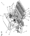
- a variant of an inventive distribution machine 10 is based on the two schematic perspective views of Figures 1A and 1B out.
- the Distributor initially has in the front region of a connecting device 12, by means of which the distributor 10 with a not shown here agricultural towing vehicle can be connected.
- a connecting device 12 In the connecting device according to the Figures 1A and 1B it is a three-point hitch.
- other appendages variants would also be conceivable, such as, for example, by means of drawbar eye or lower link suspension or any attachment or connecting device known from the agricultural sector.
- FIGS. 1 are below a reservoir 14, which serves to provide and to carry the Verteilguts, working tools 16 are arranged, wherein the working tools 16 in this case form a harrow.
- the working tools 16 in this case form a harrow.
- the distributor 10 has no working tools.
- the working tools 16 the area to be ordered or to be sowed is to be prepared and loosened accordingly, in order to thus improve the growth conditions for the plants or the material to be distributed. The loosened soil is then reconsolidated with a roller 18.
- coulters 20 which coulters are arranged with respect to the working width of the distributor 10 at regular intervals of, for example, 15 cm to each other.
- the illustrated coulters 20 are hereby designed as so-called double disc coulters. This means that they are constructed in such a way that a groove is produced in the bottom by means of two septum disks 22 arranged at an angle to one another, in which groove the distribution material is subsequently deposited by means of a seed tube 24 arranged between the two septum disks 22.
- the seed tube, a fishing reel 26 or a similar catch element may be arranged downstream.
- the furrow is closed by means of a pressure roller 28 or by means of a harrow 30.
- the pressure roller can also be used for depth control of the coulter 20 use here.
- the coulter 20 shown here as a double disc coulter represents only one possible embodiment of a coulter. In general, the use of a single-disc coulter or tine coulter or blade coulter or the like would be conceivable.
- Verteilgut is preferably volumetrically metered by a metering device located at the lower region in a desired amount.
- the distribution material is discharged into a line system 34, in which an air flow prevails, which is generated by an air conveying unit 36, such as a blower or the like.
- an air conveying unit 36 such as a blower or the like.
- the distributor tower 38 has at its upper end a distributor head 42, on the circumference of which a plurality of outlets 44 are arranged at regular intervals.
- a distributor head 42 In the distributor head 42 there is a distribution of a Verteilgutluftvolumenstroms in a plurality of Verteilgutluftvolumenströmen corresponding to the number of outlets 44.
- From the outlets 44 each carries a seed line 46 in the direction of the coulters 20 and in the direction of the coulters 20 respectively associated singulation 48. This is to note that in the FIG. 1B each of these seed lines 46 are not shown completely consistent for better understanding.
- Verteilgut is then at least largely isolated or largely homogenized by means of the singulation 48 and then passed through a seed coulter 20 associated seed tube 24 to the ground and stored in a seed furrow.
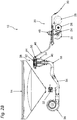
- FIGS. 2A to 2C show, with the FIGS. 2B and 2C represent the distributor 10 and their components in section.
- the cut corresponds to the Verteilgutl from the reservoir 14 to the distributor tower 38 via the outlet 44 in the direction of a coulter 20, in each case one row was shown in section here.
- Verteilgut is preferably volumetrically metered by a metering device located at the lower portion in a desired amount.
- the distribution material is discharged into a line system 34, in which an air flow prevails, which is generated by an air conveying unit 36 such as. A blower or the like.
- an air conveying unit 36 such as. A blower or the like.
- the distributor tower 38 has a distributor head 42 at its upper end. At its periphery are at regular intervals a plurality of outlets 44th arranged. In the distributor head 42 there is a distribution of the one Verteilgutluftvolumenstroms in a plurality of Verteilgutluftvolumenströmen, corresponding to the number of outlets 44. From the outlets 44 each leads a seed line 46 in the direction of the coulters 20 and in the direction of the coulters 20 respectively associated singulation 48th
- Verteilgut is then at least largely isolated or largely homogenized by means of the singulation 48 and then passed through a seed coulter 20 associated seed tube 24 to the ground and stored in a seed furrow.
- shut-off device 50 is arranged between the outlet 44 of the distributor head 42 and the separating device 48.
- This shut-off device is associated with a switch 52, by means of which the Verteilgutluftvolumenstrom can be directed either in the direction of a seed line 46 and thus in the direction of a coulter 20, or by means of which the Verteilgutluftvolumenstrom can be guided in a return area 54, via which return area 54 the Verteilgut then back in the direction of the distributor tower or the riser 40 is passed.
- a bypass 56 is integrated in the shut-off device 50.
- the return region 54 and the seed line 46 are permanently pneumatically connected, whereby at these positions largely the same pressure level prevails regardless of the respective position or position of the switch 52nd
- the distribution tower 38 consists essentially of a riser 40, at the upper end of a distributor head 42 connects. At the periphery of the distributor head 42, a plurality of outlets 44 or these downstream or in this integrated shut-off devices 50 are arranged at regular intervals.
- the distribution tower 38 initially has an arcuate transition piece 58, by means of which there is a reversal of direction of the Verteilgutluftvolumenstrom from a substantially horizontal in a vertical flow direction. Adjoining the transition piece 58 is a riser 40, which riser 40 initially has a nozzle section or a nozzle 60.
- the cross section of the riser 40 is conically reduced and then in turn conically enlarged.
- the Verteilgutluftvolumenstrom should be centered in the riser 40, whereby a subsequent uniform distribution of this is to be improved in the distributor head 42.
- other pipe sections 62 with cross-sectional tapering would also be conceivable, for example those in which only individual depressions are present. It would also be conceivable to replace the corrugated tube by a further nozzle 60, so that the riser 40 is composed of two nozzles or more.
- the individual sections of the riser 60 can each be connected by means of welding or by means of clamping pieces. Likewise, the sections may be made of a metallic or non-metallic material. Also, the riser 40 could be made in one piece and, for example. Plastic.
- a circular distributor head 42 adjoins, which has a flat cover 64.
- the Verteilgutluftvolumenstrom is deflected from a vertical in a horizontal direction, or in the direction of the outlets 44, for which purpose the Verteilgut example. May bounce against the lid 64 and then passed through the air flow in the direction of the outlets 44. The more uniform this distribution between the outlets 44, the more uniform is the transverse distribution of the Verteilguts on the agricultural machine
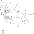
- each of the outlets 44 is a shut-off device 50 downstream.
- a pivotable switch 52 is attached.
- the switch 52 may, for example, by means of an electric and / or pneumatic and / or hydraulic and / or the like. Actuator between a closed position (see FIG. Fig. 3A right) and an open position (cf. Fig. 2C & Fig. 3A left).
- the blocking device 50 also has a return region 54, comprising a return connection 66 and a seed line connection 68 and a bypass 56.
- a claw 70 is first connected. This is formed in the exemplary embodiment y-shaped and connects two return ports 66 and two shut-off devices 28. To the claw 70, a return line 72 is also connected, which with its lower end via a nozzle 74 opens into a return device 76. With the help of the collecting pieces 70, the number of return lines 72 can be significantly reduced, in which case at least two but also more return lines 72 can be connected.
- the return device 76 is formed by a circular tube surrounding the nozzle 60 and the riser 40, respectively. Wherein the nozzle 60 in the region of its smallest diameter, a plurality of rectangular openings 78 are associated, which establish a connection between the riser 40 and the nozzle 60 and the return device 76.
- the arrangement of the openings 78 in the region of the nozzle 60 creates a suction at the openings, caused by the increased flow rate through the cross-sectional taper of the nozzle 60, whereby a Verteilgutgur arrangement from the return device 76 is further improved in the riser 40.
- the Verteilgutluftvolumenstrom is redirected in the shut-off device 50 in the direction of the return portion 54 and passed through the return port 66, the collecting pieces 70, the return line 72 and the return device 76 back into the riser 40.
- the recirculated Verteilgut is then again promoted by Verteilgutluftvolumenstrom in the riser 40 to the distributor head 42 and the outlets 44.
- the pressure levels or the air flows in the distributor head 42 are not affected or that the pressure P1 in the return device 76 or at the nozzle 74 is less than or equal the pressure P2 and P3 in the bypass 56 and 54 in the return area.
- the riser 40, the distributor head 42, the return device 76, the return region 54, the bypass 56 and the seed line connection 68 are permanently pneumatically connected, regardless of the position or the position of the switch 52. For example, located in the shut-off device 50, bypass 56 guaranteed.
- each of the metered by the metering device 32 in the line system Verteilgut be reduced accordingly, and this only from a certain number of closed outlets 44, for example, five outlets 44 may be required or is.
- the distribution tower 38 consists essentially of a riser 40, at the upper end of a distributor head 42 connects. At the periphery of the distributor head 42, a plurality of outlets 44 or these downstream shut-off devices 50 are arranged at regular intervals.
- the distribution tower 38 initially has an arcuate transition piece 58, by means of which there is a reversal of direction of the Verteilgut Kunststoffvolumenstroms from a substantially horizontal in a vertical flow direction. Adjoining the transition piece 58 is a riser 40, which riser 40 initially has a nozzle section or a nozzle 60.
- the cross section of the riser 40 is conically reduced and then in turn conically enlarged.
- the Verteilgutluftvolumenstrom should be centered in the riser 40, whereby a subsequent uniform distribution of this is to be improved in the distributor head 42.
- other pipe sections 62 with cross-sectional tapering would also be conceivable, for example those in which only individual depressions are present. It would also be conceivable to replace the corrugated tube by a further nozzle 60, so that the riser 40 is composed of two nozzles or more.
- the individual sections of the riser 60 can each be connected by means of welding or by means of clamping pieces. Likewise, the sections may be made of a metallic or non-metallic material. Also, the riser 40 could be made in one piece and, for example. Plastic.
- a circular distributor head 42 connects, which has a flat lid 64 and wherein this could also be mushroom-shaped.
- the Verteilgutluftvolumenstrom is deflected from a vertical in a horizontal direction, or in the direction of the outlets 44, for which purpose the Verteilgut example. May bounce against the lid 64 and then passed through the air flow in the direction of the outlets 44. The more uniform this distribution between the outlets 44, the more uniform is the transverse distribution of the Verteilguts on the agricultural machine.
- the pressure compensation device 80 shown in this embodiment could, in particular in conjunction with in the FIG. 3A
- Shut-off device 50 shown are combined so that, for example, at a distributor tower 38 only a small number of outlets 44 are provided with shut-off devices 50 and the rest each with pressure compensation devices 80.
Description
Die vorliegende Erfindung betrifft eine Verteilmaschine für granulatartiges Verteilgut mit den Merkmalen des unabhängigen Anspruchs 1. Die Erfindung betrifft zudem ein Verfahren zur Aussaat von granulatartigem Verteilgut mit den Merkmalen des unabhängigen Verfahrensanspruchs 9.The present invention relates to a distribution machine for granular distribution material with the features of
Verteilmaschinen werden in der Landwirtschaft zur Verteilung von granulatartigem bzw. körnigem Verteilgut wie Saatgut, Dünger oder dergl. eingesetzt. Die Verteilung erfolgt in der Regel jeweils in definierten Reihenabständen mittels verschiedenster Säschare. Die Verteilung soll jeweils derartig erfolgen, dass jedes Schar annähernd mit der gleichen Menge an Verteilgut, unabhängig von der Arbeitsbreite der Maschine, versorgt wird. Ebenfalls soll die Verteilung in Längsrichtung bzw. in Fahrtrichtung der Verteilmaschine derartig erfolgen, dass jeweils möglichst ein einzelnes Korn abgelegt wird. Von diesen als Querverteilung und Längsverteilung bezeichneten Verteilqualitäten hängt der sog. Standraum der Pflanze ab, d.h. wieviel Platz die jeweilige Pflanze auf einem Feld zur Verfügung hat, um sich entsprechend zu entwickeln, wobei auch hier wiederum gilt, je gleichmäßiger der Standraum desto gleichmäßiger der Pflanzenbestand.Distribution machines are used in agriculture for the distribution of granular or granular material such as seed, fertilizer or the like. The distribution is usually in each case in defined row spacing by means of different coulters. The distribution should in each case be such that each share is approximately supplied with the same amount of Verteilgut, regardless of the working width of the machine. Likewise, the distribution in the longitudinal direction or in the direction of travel of the distributor should be such that in each case as far as possible a single grain is deposited. Of these distribution qualities, called transverse distribution and longitudinal distribution, the so-called plant standing space depends on the plant, i. how much space the particular plant has on a field in order to develop accordingly, again, the more even the stand space the more even the plant stock.
Die Verteilmaschinen können generell in drei Hauptkategorien eingeteilt werden; nämlich in mechanisch arbeitende oder pneumatisch arbeitende Drillmaschinen sowie in Einzelkornsämaschinen, wobei wiederum jeder dieser Maschinentypen für ein spezielles Aussaatverfahren bevorzugt Verwendung findet. Mechanisch und pneumatisch arbeitende Verteilmaschinen werden insbesondere zur Drillsaat verwendet, während die Einzelkornsämaschinen insbesondere zur vereinzelten bzw. vergleichmäßigten Einzelkornsaat eingesetzt werden.The distribution machines can generally be divided into three main categories; namely in mechanically or pneumatically operated seed drills as well as in precision seed drills, whereby in turn each of these types of machines is preferably used for a special sowing method. Mechanically and pneumatically operated distribution machines are used in particular for drilled sowing, while the precision seed drills are used in particular for isolated or uniformed single-seed sowing.
Mittels aus dem Stand der Technik bekannt gewordener Einzelkornsämaschinen erfolgt eine vereinzelte bzw. vergleichmäßigte Kornabgabe des Verteilguts in der Reihe mit teilweise großen Reihenabständen der Säschare zueinander; diese Reihenabstände quer zur Fahrtrichtung können bspw. 45cm oder 70cm oder 80cm betragen. Auch werden derartige Einzelkornsämaschinen derzeit in erster Linie für Verteilgüter verwendet, mittels derer eine relativ geringe Anzahl von Körner je Fläche (typische Maßeinheit: Körner / m2) ausgebracht werden soll. Bei diesen Verteilgütern handelt es sich bspw. um Mais, Soja oder dergl. So werden u.a. bei Mais ca. 9 Körner / m2 ausgebracht. Dadurch ergeben sich für die zur Vereinzelung des Verteilguts vorgesehenen Vereinzelungsvorrichtungen entsprechend geringe Frequenzen der Verteilgutvereinzelung, welche mit aus dem Stand der Technik bekannt gewordenen Vereinzelungsvorrichtungen erreicht werden können.By means of known from the prior art precision seeders is a scattered or gleichmäßigte grain delivery of the Verteilguts in the row with partially large row spacing of the coulters to each other; This row spacing across the direction of travel can be, for example, 45cm or 70cm or 80cm. Also, such precision seeders are currently used primarily for distribution, by means of which a relatively small number of grains per area (typical unit: grains / m 2 ) to be applied. These distribution goods are, for example, corn, soybeans or the like. Thus, for example, about 9 grains / m 2 are applied to corn. This results in correspondingly low frequencies of the Verteilgutvereinzelung for the purpose of separating the Verteilguts separating devices, which can be achieved with known from the prior art separating devices.
Zur Aussaat von Verteilgütern mit größerer Anzahl von Körner / m2, wie es bspw. für Weizen typisch ist, finden in der Regel pneumatisch arbeitende Verteilmaschinen Verwendung. Eine vereinzelte Verteilung des Verteilguts in der Reihe war hierbei bislang nicht bzw. nur bei geringen Fahrtgeschwindigkeiten der Verteilmaschine möglich, da bei Weizen bspw. 350 Körner / m2 ausgebracht werden, was wiederum sehr hohe Vereinzelungsfrequenzen der Vereinzelungsvorrichtungen voraussetzt. Um auch hier noch einen möglichst gleichmäßigen Standraum für die Pflanze schaffen zu können, weisen derartige Maschinen in der Regel einen geringeren Reihenabstand von bspw. nur 12,5 cm oder 15 cm auf, und die Verteilung erfolgt jeweils als Drillsaat, d.h. ohne exakte Kornvereinzelung in den einzelnen Reihen.For sowing of distribution goods with a larger number of grains / m 2 , as is typical, for example, for wheat, usually find pneumatically operating distribution machines use. An occasional distribution of the Verteilguts in the series was not possible here or only at low speeds of the distributor, since in wheat, for example, 350 grains / m 2 are applied, which in turn requires very high separation frequencies of the separating devices. In order to still be able to create the most even foot space for the plant here, such machines usually have a smaller row spacing of, for example, only 12.5 cm or 15 cm, and the distribution takes place in each case as Drillsaat, ie without exact grain separation in the individual rows.
Ein Lösungsansatz für eine Vereinzelungsvorrichtung zur Vereinzelung von Verteilgut wie Weizen mit einer großen Anzahl von Körnern, die pro Flächeneinheit ausgebracht werden (Körner / m2), geht bspw. aus der
Neben einer vereinzelten Verteilgutabgabe bei einer guten Querverteilung ist es zudem wünschenswert, dass einzelne Abgänge bzw. einzelne Schare beliebig zu- und weggeschaltet werden können, so dass Überlappungen von bereits bestellten Flächen mit Verteilgut möglichst unterbunden werden. Dies wird typischerweise als "Section-Control" bezeichnet, wobei auch der Begriff des "Precision Farming" hierfür verwendet wird. Insbesondere sind solche Steuerungseingriffe erforderlich, wenn eine Maschinensteuerung auf Basis von GPS-Daten erfolgen soll.In addition to a scattered Verteilgutabgabe with a good lateral distribution, it is also desirable that individual outlets or individual shares can be arbitrarily switched on and off, so that overlaps of already ordered areas with Verteilgut be prevented as possible. This is typically referred to as "section control", whereby the term "precision farming" is used for this purpose. In particular, such control interventions are required if a machine control based on GPS data is to take place.
Ein System zur Verbesserung der Verteilqualität bzw. insbesondere zur Verbesserung der Querverteilung in einer pneumatisch arbeitenden Verteilmaschine geht aus der
Eine weitere Verteilmaschine geht aus der
Die
Ziel der vorliegenden Erfindung ist es daher, eine Verteilmaschine zur Verfügung zu stellen, mittels derer eine vereinzelte Kornabgabe von Verteilgütern mit einer großen Anzahl an ausgebrachten Körnern je Flächeneinheit (Körner / m2) ermöglicht wird, bei welcher die Vereinzelung weitgehend unabhängig von der Anzahl an Säscharen erfolgt, und bei der Abgänge beliebig zu- und abschaltbar sind, ohne dass hierdurch die Verteilqualität beeinflusst wird. Ziel ist es ferner, eine Verteilmaschine zu schaffen, welche sowohl die Eigenschaften einer Verteilmaschine zur Drillsaat als auch die Eigenschaften einer Verteilmaschine zur Einzelkornsaat aufweist. Zudem ist es Ziel der Erfindung, ein entsprechendes Verfahren zur Verteilung von granulatartigem Verteilgut zur Verfügung zu stellen.The aim of the present invention is therefore to provide a distributor, by means of which a scattered grain delivery of Verteilgütern with a large number of applied grains per unit area (grains / m 2 ) is made possible, in which the separation largely independent of the number Säscharen occurs, and can be switched on and off at the outlets as desired, without affecting the distribution quality. The aim is also to provide a distributor, which has both the properties of a distributor for Drillsaat and the properties of a distributor for single grain sowing. In addition, it is an object of the invention to provide a corresponding method for the distribution of granular distribution material available.
Diese Ziele der Erfindung werden durch eine Verteilmaschine mit den Merkmalen des unabhängigen Anspruchs 1 sowie durch ein Verfahren mit den Merkmalen des unabhängigen Anspruchs 9 erreicht, wobei weitere vorteilhafte Ausgestaltungen und Weiterbildungen der Erfindung aus den jeweiligen abhängigen Ansprüchen hervorgehen.These objects of the invention are achieved by a distributor with the features of
Zur Erreichung der genannten Ziele schlägt die Erfindung eine Verteilmaschine zur Verteilung von granulatartigem Verteilgut wie Saatgut, Dünger oder dergl. vor. Die Maschine besitzt zunächst einen Vorratsbehälter, mittels welchem das auszubringende Verteilgut bereitgestellt bzw. mit der Verteilmaschine mitgeführt wird. Dem Vorratsbehälter nachgeordnet ist eine Dosiervorrichtung, mittels welcher das Verteilgut in einer definierbaren Menge bspw. volumetrisch in ein Leitungssystem zugeführt wird. Im Leitungssystem herrscht ein Luftvolumenstrom vor, welcher durch eine Luftfördereinheit wie bspw. einem Gebläse oder dergl. erzeugt wird. Im Leitungssystem entsteht somit ein Verteilgutluftvolumenstrom. Durch diesen Verteilgutluftvolumenstrom wird das Verteilgut innerhalb der Verteilmaschine befördert.To achieve the stated objectives, the invention proposes a distribution machine for distributing granular material such as seeds, fertilizer or the like before. The machine initially has a reservoir, by means of which the auszubringende Distributed provided or carried along with the distributor. Downstream of the reservoir is a metering device, by means of which the material to be dispensed is supplied in a definable amount, for example volumetrically in a line system. In the line system prevails an air flow, which is generated by an air conveying unit such as. A blower or the like. In the line system thus creates a Verteilgutluftvolumenstrom. This Verteilgutluftvolumenstrom the Verteilgut is transported within the distributor.
Das Verteilgut wird anschließend entlang des Leitungssystems in Richtung eines Verteilerturms gefördert, wobei der Verteilerturm wiederum ein Steigrohr zur Aufnahme und Weiterleitung des Verteilgutluftvolumenstroms aufweist. Das Steigrohr kann bspw. als Wellrohr ausgebildet und senkrecht in der Verteilmaschine in der Nähe der Säschare angebracht sein. Des Weiteren könnte das Steigrohr in dessen Verlauf eine Querschnittsverjüngung aufweisen, welche derartig gebildet ist, dass sich in diesem Bereich die Durchflussgeschwindigkeit erhöht sowie der Verteilgutluftvolumenstrom zentriert wird.The material to be conveyed is subsequently conveyed along the line system in the direction of a distribution tower, wherein the distribution tower in turn has a riser pipe for receiving and passing the Verteilgutluftvolumenstroms. The riser may be formed, for example, as a corrugated pipe and mounted vertically in the distributor in the vicinity of the coulters. Furthermore, in the course of the riser, it could have a cross-sectional taper which is formed in such a way that it has a cross-sectional taper Range increases the flow rate and the Verteilgutluftvolumenstrom is centered.
An das Steigrohr schließt ein Verteilerkopf bzw. ein Hauptverteiler an. Dieser Hauptverteiler könnte bspw. einen pilzförmigen Deckelbereich oder einen flachen Deckelbereich aufweisen. Am Umfang des Verteilerkopfs sind eine Mehrzahl von einzelnen Abgängen angeordnet. Das Verteilgut, welches mittels des Steigrohrs in Richtung des Verteilerkopfes gefördert wird, wird in diesem zu einer Mehrzahl, entsprechend der Anzahl von Abgängen, einzelner Verteilgutluftvolumenströmen aufgeteilt. Diese Verteilung kann u.a. auch durch die Ausgestaltung des Deckelbereichs entsprechend beeinflusst werden, da je nach Form dieses, dass gegen diesen prallende Verteilgut entsprechend anders umgelenkt wird.The riser is followed by a distributor head or a main distributor. This main distributor could, for example, have a mushroom-shaped cover area or a flat cover area. At the periphery of the distributor head a plurality of individual outlets are arranged. The distribution material, which is conveyed by means of the riser in the direction of the distributor head, is divided therein in a plurality, corresponding to the number of outlets, individual Verteilgutluftvolumenströmen. This distribution can i.a. be influenced accordingly by the design of the lid area, since, depending on the shape of this, that is deflected according to this differently against this bouncing Verteilgut.
Die Anzahl an Abgängen ist vorzugsweise identisch zu einer Anzahl von ebenfalls an der Verteilmaschine angebrachten Säscharen, wobei die Anzahl an Abgängen zur Anzahl an Scharen auch variieren kann. Die Säschare können auf verschiedenste Art und Weise ausgebildet sein. So können diese bspw. als aus dem Stand der Technik bekannte Doppelscheibenschare oder Einscheibenschare oder Zinkenschare oder dergl. ausgebildet sein.The number of outlets is preferably identical to a number of coulters also attached to the distributor, and the number of outlets to the number of coulters may also vary. The coulters can be designed in various ways. Thus, these may be formed, for example, as known from the prior art double disc coulters or single disc coulters or tine coulters or the like.
Den Säscharen zugeordnet ist jeweils eine Vereinzelungsvorrichtung, welche Vereinzelungsvorrichtung vorzugsweise der durch die
In einer bevorzugten Ausgestaltung umfasst die Vereinzelungsvorrichtung ein Gehäuse mit einer annähernd kreisbahn- und/oder kreissegmentförmiger Innenmantelfläche, wenigstens eine Einlassöffnung für befördertes granulatartiges Verteilgut oder Körner, eine im Gehäuse konzentrisch rotierende Fördereinrichtung für das beförderte Verteilgut bzw. die Körner sowie wenigstens eine Auslassöffnung die annähernd tangential an die Innenmantelfläche des Gehäuses anschließt, wobei die Fördereinrichtung eine oder mehrere Öffnungen und/oder Absätze an ihrem Außenbereich bzw. in der Nähe ihres Außenumfangs aufweist, die in einem ersten Gehäuse- und/oder Förderbereich mit der Gehäuseinnenmantelfläche eine Fördertasche bildet bzw. bilden, in der die Körner gedrängt werden und durch Zentrifugalkräfte, unterstützt durch die Fördereinrichtung, kreisbogenförmig befördert werden und in einem zweiten Gehäuse- und/oder Vereinzelungsbereich durch eine veränderte Kontur der Innenmantelfläche des Gehäuses nur jeweils ein einzelnes Korn weiterhin unter Zentrifugalkrafteinflüssen in der Öffnung bzw. im Absatz der Fördereinrichtung verbleibt und überschüssige Körner abgesondert werden und diese wiederum zur erneuten Förderung in den ersten Gehäusebereich zurückgeführt werden, wobei wiederum Mitnehmer der Fördereinrichtung mit der Innenmantelfläche des Gehäuses eine Fördertasche bilden, wobei die Mantelfläche von einen breiten in einen schmal werdenden Bereich übergeht, so dass die schmale Mantelflächenbreite nur noch ausreichend Führung für ein zu förderndes Korn bietet.In a preferred embodiment, the separating device comprises a housing with an approximately kreisbahn- and / or circular segment-shaped inner surface, at least one inlet opening for transported granular material or grains, a concentrically rotating in the housing conveyor for the transported Verteilgut or grains and at least one outlet opening approximately connected tangentially to the inner circumferential surface of the housing, wherein the conveyor has one or more openings and / or paragraphs at its outer region or in the vicinity of its outer periphery, in a first Housing and / or conveying area with the Gehäuseinnenmantelfläche forms a conveyor pocket or form in which the grains are urged and centrifugal forces, supported by the conveyor, are conveyed in a circular arc and in a second housing and / or dicing by an altered contour of the inner circumferential surface the housing only a single grain remains under centrifugal force in the opening or in the heel of the conveyor and surplus grains are separated and these in turn are returned for renewed promotion in the first housing portion, in turn driver of the conveyor with the inner surface of the housing a conveyor pocket form, wherein the lateral surface of a wide merges into a narrowing area, so that the narrow lateral surface width only provides sufficient guidance for a grain to be conveyed.
Das Säschar weist ein Saatrohr auf, mittels welchem das durch die Vereinzelungsvorrichtung vereinzelte bzw. vergleichmäßigte Verteilgut in Richtung einer mittels des Säschar gezogenen Saatfurche geleitet wird. Das Verteilgut kann auch entlang des Saatrohrs von einer Luftströmung getragen werden bzw. von dieser beschleunigt werden, vorzugsweise auf eine Geschwindigkeit, welche größer ist als die Fallgeschwindigkeit.The coulter has a seed tube, by means of which the product separated or evened by the singling device is conducted in the direction of a seed furrow pulled by means of the coulter. The material to be spread can also be carried along the seed tube by or be accelerated by an air flow, preferably to a speed which is greater than the falling speed.
Die Verbindung zwischen den Abgängen und den Säscharen bzw. den Vereinzelungsvorrichtungen erfolgt mittels einer Saatleitung, wobei diese Saatleitung in die Vereinzelungsvorrichtung mündet und das Verteilgut innerhalb dieser mittels einer Luftvolumenströmung gefördert werden kann. Diese Luftvolumenströmung kann ebenso zur Unterstützung der Vereinzelung der Vereinzelungsvorrichtung dienen sowie zur Erzeugung der Luftvolumenströmung innerhalb des Saatrohrs.The connection between the outlets and the coulters or the separating devices by means of a seed line, said seed line opens into the separating device and the Verteilgut can be promoted within this by means of an air volume flow. This air volume flow can also serve to assist the separation of the singulation device and to generate the air volume flow within the seed tube.
Zwischen dem Abgang des Verteilerkopfs bzw. in diesen integriert und der Vereinzelungsvorrichtung ist erfindungsgemäß eine Absperrvorrichtung angeordnet. Diese Absperrvorrichtung weist eine Weiche auf, mittels derer der Verteilgutluftvolumenstrom zum einen in Richtung eines Rückführbereichs oder zum anderen in Richtung des Säschar bzw. in Richtung der Vereinzelungsvorrichtung geleitet werden kann. Der Rückführbereich ist in diesem Zusammenhang derartig zu verstehen, dass mittels diesem das Verteilgut nach bspw. einem Abschalten eines Abganges in Richtung der Steigleitung oder in Richtung des Vorratsbehälters oder in einen anderen Maschinenbereich wie bspw. das Leitungssystem zurückgeleitet wird und dieses Verteilgut anschließend nochmals in den Verteilerkopf gefördert werden kann.Between the outlet of the distributor head or in this integrated and the separating device according to the invention a shut-off device is arranged. This shut-off device has a switch, by means of which the Verteilgutluftvolumenstrom can be directed to one in the direction of a return area or the other in the direction of the coulter or in the direction of the separating device. The return area is to be understood in this context such that by means of this the Verteilgut after eg a shutdown of a departure in the direction of the riser or in the direction of the reservoir or in another machine area such as the conduit system is returned and this Verteilgut then again in the Distributor head can be promoted.
Durch einen erfindungsgemäßen Aufbau der Verteilmaschine wird somit eine Verteilmaschine geschaffen, welche gegenüber den aus dem Stand der Technik bekannten Verteilmaschinen eine Reihe von Verbesserungen aufweist. So wird durch die Zuordnung einer Vereinzelungsvorrichtung an jedem Schar eine wesentliche Verbesserung der Längsverteilung ermöglicht, unabhängig von der Arbeitsbreite der Maschine und unabhängig von der Anzahl an Reihen. Darüber hinaus wird durch die Rückführung des Verteilguts bei einem Abschalten eines Abgangs zurück in das Steigrohr oder in den Vorratsbehälter oder in einen anderen Maschinenbereich, die Verteilung des Verteilguts auf die anderen Abgänge nicht verschlechtert, da die Querschnitte und somit die Luftströmungen im Verteilerkopf unabhängig von der Stellung der Weiche jeweils gleich bleiben, d.h. die Stellung der Weiche hat keinen Einfluss auf die Wirkungsweise des Verteilerkopfs. Somit ist es mittels der Weiche jederzeit möglich, beliebig viele Abgänge zu- oder abzuschalten, ohne dass hierbei die Querverteilung der Verteilmaschine beeinflusst oder gar verschlechtert wird. Durch eine derartige Ausgestaltung der Verteilmaschine wird somit ein Section Control System bzw. eine GPS basierte Steuerung in Verbindung mit einer vereinzelten Kornabgabe ermöglicht, wodurch die aus dem Stand der Technik bekannten, jeweils nur einer Art von Verteilmaschinen zugeordneten Vorteile somit in einer Verteilmaschine vereint werden, d.h. es wird somit eine Verteilmaschine geschaffen, welche den Aufbau einer Verteilmaschine zur Drillsaat besitzt jedoch mittels dieser eine Einzelkornabgabe ermöglicht wird und ebenso ein Section Control System geschaffen wird.By a construction according to the invention of the distributor, a distributor is thus created, which has a number of improvements over the distribution machines known from the prior art. Thus, the allocation of a separating device on each share a significant improvement in the longitudinal distribution allows, regardless of the working width of the machine and regardless of the number of rows. In addition, the return of the Verteilguts when switching off a departure back into the riser or in the reservoir or in another machine area, the distribution of the Verteilguts to the other outlets not deteriorated, since the cross sections and thus the air flows in the header independent of the Position of the switch remain the same, ie the position of the switch has no influence on the mode of action of the distributor head. Thus, by means of the switch at any time it is possible to connect or disconnect any number of outlets without the transverse distribution of the distributor being influenced or even worsened. Such a configuration of the distribution machine thus enables a sectional control system or a GPS-based control in conjunction with a scattered emission of grain, whereby the advantages known from the prior art and associated with only one type of distribution machine are thus combined in one distribution machine. ie It is thus created a distributor, which has the structure of a distributor for Drillsaat but by means of which a single-grain delivery is made possible and also a section control system is created.
In einer bevorzugten Form entspricht der Verteilerturm dem Verteilerturm, wie er durch die deutsche Patentanmeldung mit der Anmeldenummer
Es kann vorgesehen sein, dass mittels der Dosiervorrichtung das Verteilgut in einer definierten Menge volumetrisch in den Luftvolumenstrom dosiert wird.It can be provided that the material to be dispensed is metered volumetrically into the air volume flow by means of the metering device in a defined amount.
In einer bevorzugten Ausgestaltungvariante weist die Absperrvorrichtung neben einem ersten Bereich zur Weiterleitung des Verteilguts in Richtung der Saatleitung bzw. in Richtung der Vereinzelungsvorrichtung sowie einen zweiten Bereich zur Weiterleitung des Verteilguts in Richtung des Rückführbereichs einen dritten Bereich bzw. einen Bypass auf, mittels welchem der erste Bereich und der zweite Bereich dauerhaft pneumatisch verbunden werden, so dass unabhängig von der Stellung der Weiche in der Absperrvorrichtung sowie in den angrenzenden Komponenten jeweils die gleichen Druckniveaus vorherrschen, wodurch sich in diesen ein jeweils weitgehend gleiches Druckniveau einstellt.In a preferred embodiment variant, the shut-off device, in addition to a first region for forwarding the Verteilguts in the direction of the seed line or in the direction of the separating device and a second area for forwarding the Verteilguts in the direction of the return area on a third area or a bypass, by means of which the first Area and the second area permanently pneumatically connected, so that regardless of the position of the switch in the shut-off device and in the adjacent components in each case the same Pressure levels prevail, which sets in each of a largely the same pressure level.
Der Verteilerturm weist ein Steigrohr auf, mittels welchem das auszubringende Verteilgut mit Hilfe eines Luftvolumenstroms in Richtung eines an das Steigrohr anschließenden, vorzugsweise ringförmigen, Verteilerkopfes befördert wird. Der Verteilerkopf weist über dessen Umfang verteilt eine Mehrzahl von Abgängen bzw. Reihen auf, mittels welchen Abgängen der durch das Steigrohr beförderte und im Verteilkopf entsprechend der Anzahl an Abgängen aufgeteilte Verteilgutluftvolumenstrom in Richtung von bspw. im Boden oder Bodennah geführten Säscharen wie Scheibenschare, Zinkenschare oder dergl. befördert wird. Zumindest einem der Abgänge zugeordnet bzw. in diesen integriert oder zwischen Abgang und Säschar angeordnet, ist eine Absperrvorrichtung, wobei diese eine Weiche aufweist. Mit dieser Weiche kann der in den Abgängen vorhandene Verteilgutluftvolumenstrom in Richtung einer Saatleitung oder in Richtung eines Rückführbereichs bzw. einer Rückführeinrichtung umgeleitet werden, wobei der Rückführbereich bzw. die Rückführeinrichtung und die Saatleitung mittels eines Bypass pneumatisch verbunden sind. Der Rückführbereich mündet bspw. in einer Rückführeinrichtung, welche bspw. das Saatrohr umgibt bzw. Teil dieses ist, wobei das Saatrohr im Bereich der Rückführeinrichtung Öffnungen aufweist, mittels denen das Steigrohr sowie die Rückführeinrichtung pneumatisch verbunden werden. Auch wäre es denkbar, dass der Rückführbereich bspw. in den Vorratsbehälter oder in das Leitungssystem mündet, wobei jeweils das Steigrohr, die Rückführeinrichtung, der Rückführbereich, der Bypass sowie die Saatleitung permanent pneumatisch verbunden sind, unabhängig der jeweiligen Stellung bzw. Position der Weiche. Dadurch stellt sich bspw. in der Rückführeinrichtung ein Druckniveau P1 sowie im Rückführbereich (Druckniveau P3) bzw. im Bypass ein Druckniveau P2 ein, wobei hierbei P1 kleiner oder gleich zu P2 ist. Diese Druckniveaus herrschen unabhängig von der Stellung der Weiche sowie unabhängig von der Anzahl an verschlossenen Abgängen, wodurch eine beliebige Anzahl von Abgängen verschlossen werden kann, sowie äußere Einflüsse wie variable Saatleitungslängen oder dergl. keine bzw. vernachlässigbare Auswirkungen auf die Querverteilung der landwirtschaftlichen Verteilmaschine haben, wodurch alle Vereinzelungsvorrichtungen, unabhängig von der Anzahl an verschlossenen Abgängen bzw. unabhängig von der Position der Weiche dauerhaft mit weitgehend der gleichen Menge an Verteilgut versorgt werden.The distributor tower has a riser pipe, by means of which the distributor material to be delivered is conveyed by means of an air volume flow in the direction of a preferably annular, distributor head adjoining the riser pipe. The distributor head has distributed over the circumference of a plurality of outlets or rows, by means of which outlets transported through the riser and distributed in the distribution head according to the number of outlets Verteilgutluftvolumenstrom in the direction of eg ground or ground near coulters such as disc coulters, Zinkenschare or the like is transported. At least one of the outlets assigned or integrated into this or arranged between departure and coulter, is a shut-off device, which has a switch. With this switch the Verteilgutluftvolumenstrom existing in the outlets can be redirected in the direction of a seed line or in the direction of a return area or a return device, wherein the return area or the return device and the seed line are pneumatically connected by means of a bypass. The return area opens, for example, in a return device, which, for example, surrounds or is part of the seed tube, wherein the seed tube has openings in the area of the return device, by means of which the standpipe and the return device are pneumatically connected. It would also be conceivable for the return region to open, for example, into the storage container or into the line system, whereby in each case the riser pipe, the return device, the return region, the bypass and the seed line are permanently pneumatically connected, irrespective of the respective position or position of the switch. As a result, for example, a
Es kann außerdem vorgesehen sein, dass zumindest zwischen einem Abgang und einer Vereinzelungsvorrichtung eine Druckausgleichsvorrichtung zugeordnet ist.It can also be provided that at least between a departure and a separating device is associated with a pressure compensation device.
Durch den Bypass herrschen somit unabhängig von der Stellung der Weiche auch im Bereich der Vereinzelungsvorrichtung jeweils die gleichen Druckniveaus, wodurch wiederum eine Vereinzelungsqualität durch eine Veränderung der Stellung der Weiche nicht negativ beeinflusst wird, da insbesondere die Volumenströme in der Vereinzelungsvorrichtung sowie die Druckniveaus in den Saatleitungen zu den Vereinzelungsvorrichtungen durch den Bypass jeweils weitgehend identisch zueinander sind, wodurch an den Vereinzelungsvorrichtungen jeweils die weitgehend gleichen Bedingungen herrschen.Thus, regardless of the position of the switch, the same pressure levels also prevail in the area of the separating device due to the bypass, which in turn does not adversely affect a separation quality by changing the position of the switch, since in particular the volume flows in the separating device and the pressure levels in the seed lines to the separating devices through the bypass are each substantially identical to each other, whereby prevail at the separating devices each largely the same conditions.
Die Rückführeinrichtung kann auf verschiedenste Weise ausgestaltet sein. So wäre es denkbar, dass diese als Rohr ausgebildet ist, welche das Steigrohr umgibt, wobei das Steigrohr im Bereich der Rückführeinrichtung Öffnungen aufweist, wodurch das Steigrohr sowie die Rückführeinrichtung pneumatisch verbunden sind. Durch die Öffnungen kann darüber hinaus das Verteilgut aus der Rückführeinrichtung zurück zum Steigrohr befördert oder geleitet werden. An der Rückführeinrichtung können darüber hinaus, vorzugsweise entlang des Umfangs eine Mehrzahl von Stutzen angebracht sein, an welchen wiederum Rückleitungen angebracht sind, welche eine Verbindung zwischen dem Rückführbereich und der Rückführeinrichtung herstellen. Darüber hinaus könnte die Rückführeinrichtung trichterförmig gebildet sein, welcher Trichter das Steigrohr umgibt und zum einen im Bereich der Öffnungen im Steigrohr und zum anderen in den Rückführbereich mündet. Durch eine derartige Ausgestaltung könnte der Teileaufwand wesentlich reduziert werden.The return device can be designed in various ways. So it would be conceivable that this is designed as a tube which surrounds the riser, wherein the riser in the region of the return means has openings, whereby the riser and the return means are pneumatically connected. In addition, through the openings, the material to be conveyed out of the return device can be conveyed or guided back to the riser pipe. Moreover, a plurality of nozzles may be attached to the return device, preferably along the circumference, to which in turn return lines are attached, which establish a connection between the return region and the return device. In addition, the return device could be formed funnel-shaped, which funnel surrounds the riser and opens on the one hand in the region of the openings in the riser and the other in the return area. By such a configuration, the parts cost could be substantially reduced.
Der Rückführbereich kann auf verschiedenste Weise gebildet werden. So kann dieser bspw. als Rückführöffnung, welche bspw. in der Bodenfläche des Verteilerkopfs oder eines der Abgänge bzw. der Absperrvorrichtung angebracht ist, ausgeführt sein. Ebenso kann die Absperrvorrichtung einen Rückführanschluss aufweisen, welcher als Rückführbereich dient. Ebenso könnten der Rückführbereich und die Rückführeinrichtung eine Einheit bilden, insbesondere wenn die Rückführeinrichtung als trichterförmiges Element gebildet ist, welches bspw. mit dessen unterem Ende im Bereich der Öffnungen des Steigrohrs mündet und welches mit dessen oberem Ende im Bereich der Rückführöffnungen des Verteilerkopf oder der Absperrvorrichtung mündet. An den Rückführbereich könnte jedoch auch mittels eines Rückführanschlusses eine Rückleitung angeschlossen werden, welche in die Rückführeinrichtung mündet. Ebenso könnten mittels eines Sammelstücks zwei oder mehr Rückführbereiche verbunden bzw. gekoppelt werden sowie an das Sammelstück wiederum eine Rückleitung angeschlossen werden.The return area can be formed in various ways. Thus, this example, as a return opening, which, for example. In the bottom surface of the distributor head or one of the outlets or the shut-off device is mounted, be executed. Likewise, the shut-off device may have a return port, which serves as a return area. Likewise, the return region and the return device could form a unit, in particular if the return device is formed as a funnel-shaped element, which opens, for example, with its lower end in the region of the openings of the riser and which with its upper end in the region of the return openings of the distributor head or the shut-off device empties. However, a return line, which opens into the return device, could also be connected to the return region by means of a return connection. Likewise, two or more return areas could be connected or coupled by means of a claw and in turn connected to the claw a return line.
Ein Positionswechsel der Weiche der Absperrvorrichtung erfolgt erfindungsgemäß mittels eines Stellantriebs, vorzugsweise mittels eines elektrisch- und/oder pneumatisch- und/oder hydraulisch arbeitenden Stellantriebs. Ebenso erfolgt der Antrieb der Vereinzelungsvorrichtung erfindungsgemäß mittels eines motorischen Antriebs, bspw. mittels eines elektrischen- und/oder eines pneumatischen- und/oder eines hydraulischen Antriebes bzw. Motors, wobei der Stellantrieb und der motorische Antrieb erfindungsgemäß jeweils gemeinsam betätigt werden. Diese können jeweils so angesteuert werden, dass bei einem Zu- oder Abschalten eines Abgangs jeweils der Stellantrieb und der Antrieb gemeinsam betätigt werden.A change of position of the switch of the shut-off device according to the invention by means of an actuator, preferably by means of an electrically and / or pneumatically and / or hydraulically operating actuator. Likewise, the drive of the separating device according to the invention by means of a motor drive, eg. By means of an electric and / or pneumatic and / or hydraulic drive or motor, wherein the actuator and the motor drive according to the invention are each operated together. These can each be controlled in such a way that, in the event of an activation or deactivation of an outlet, the actuator and the drive are actuated together.
Des Weiteren wäre es vorstellbar, dass das Ein- bzw. Ausschalten des Stellantriebs und des Antriebs jeweils in Abhängigkeit der Position der Verteilmaschine erfolgt. Bewegt sich die Verteilmaschine in Richtung eines Vorgewende oder in Richtung einer bereits bestellten Fläche könnte bspw. zuerst der Stellantrieb die Weiche betätigen bzw. den Abgang schließen und das Verteilgut in Richtung eines Rückführbereichs lenken sowie zeitversetzt anschließend der Antrieb die Vereinzelungsvorrichtung abschalten. Umgekehrt könnte bspw. beim Einsetzen der Maschine nach einem Vorgewende geschaltet werden. Das Positionssignal könnte auf Basis von GPS-Daten in eine Rechnereinheit übermittelt werden, mittels derer der Stellantrieb und der Antrieb geschaltet werden. Auch wäre es denkbar, dass der Stellantrieb und der Antrieb auf Basis der Position der Säschare geschaltet werden. Das bedeutet: Sind die Säschare in einer ausgehobenen Position, werden der Stellantrieb und der Antrieb jeweils abgeschaltet; befinden sie sich in einer abgesenkten Arbeitsposition, werden der Stellantrieb und der Antrieb eingeschaltet, wobei dies erfindungsgemäß auch zeitversetzt erfolgen kann.Furthermore, it would be conceivable that the switching on and off of the actuator and the drive takes place in each case depending on the position of the distributor. If the distributor moves in the direction of a headland or in the direction of an already ordered surface, for example, the actuator could first actuate the switch or close the outlet and direct the material to be conveyed in the direction of a return region, and then the drive switches off the separating device with a time delay. Conversely, for example, could be switched when inserting the machine for a headland. The position signal could be transmitted on the basis of GPS data in a computer unit, by means of which the actuator and the drive are switched. It would also be conceivable that the actuator and the drive are switched based on the position of the coulters. This means: If the coulters are in a raised position, the actuator and the drive are switched off; If they are in a lowered working position, the actuator and the drive are switched on, and according to the invention this can also take place with a time delay.
Die Erfindung sieht weiterhin ein Verfahren zur Verteilung von granulatartigem Verteilgut wie Saatgut, Dünger oder dergl. vor. Das Verfahren umfasst hierbei zunächst die Bereitstellung des Verteilguts mittels eines Vorratsbehälters sowie die anschließende vorzugsweise volumetrische Dosierung des Verteilguts mittels einer dem Vorratsbehälter nachgeordneten Dosiervorrichtung, wobei das Verteilgut anschließend in ein Leitungssystem abgegeben wird, in welchem Leitungssystem ein Luftvolumenstrom, vorzugsweise erzeugt durch eine Luftfördereinheit bzw. durch ein Gebläse, vorhanden ist, wodurch ein Verteilgutluftvolumenstrom erzeugt wird.The invention further provides a method for distributing granular material such as seeds, fertilizer or the like. The method comprises firstly the provision of the Verteilguts by means of a reservoir and the subsequent preferably volumetric dosing of the Verteilguts by means of a downstream of the reservoir metering device, wherein the Verteilgut is subsequently discharged into a conduit system, in which line system an air flow, preferably generated by an air conveyor unit or by a blower, whereby a Verteilgutluftvolumenstrom is generated.
Anschließend wird dieser Verteilgutluftvolumenstrom einem Verteilerturm zugeführt, wobei der Verteilerturm ein Steigrohr zur Aufnahme des Verteilgutluftvolumenstroms aufweist und wobei an das Steigrohr ein Verteilerkopf anschließt. In diesem Verteilerkopf erfolgt eine Aufteilung des einen Verteilgutluftvolumenstroms in eine Mehrzahl von Verteilgutluftvolumenströmen, entsprechend einer Anzahl von über dessen Umfang verteilten Abgängen.Subsequently, this Verteilgutluftvolumenstrom a distribution tower supplied, wherein the distributor tower has a riser for receiving the Verteilgutluftvolumenstroms and wherein the riser is followed by a distribution head. In this distribution head is a division of the one Verteilgutluftvolumenstroms in a plurality of Verteilgutluftvolumenströmen, corresponding to a number of distributed over its circumference outlets.
Weiter sind der Verteilmaschine eine Mehrzahl von Säscharen bspw. entsprechend der Anzahl von Abgängen zugeordnet, mittels welchen Säscharen das Verteilgut im Boden abgelegt wird. Wobei wiederum den Säscharen jeweils eine Vereinzelungsvorrichtung zugeordnet ist, mittels welcher das durch die Luftvolumenströmung durch eine Saatleitung getragene Verteilgut jeweils vergleichmäßigt oder vereinzelt wird und anschließend über ein Saatrohr im Boden abgelegt wird.Furthermore, the distributor is assigned a plurality of coulters, for example, corresponding to the number of outlets, by means of which coulters the product is deposited in the ground. Wherein in turn the coulters are each assigned a separating device, by means of which the distribution of air carried by the air volume flow through a seed line is in each case uniformed or separated and is then deposited via a seed tube in the ground.
Das Verfahren sieht weiter vor, dass zwischen dem Abgang des Verteilkopfs und der Vereinzelungsvorrichtung eine Absperrvorrichtung angeordnet ist, wobei die Absperrvorrichtung eine Weiche aufweist, mittels derer der Verteilgutluftvolumenstrom wahlweise in Richtung der Saatleitung oder in Richtung eines Rückführbereich geleitet werden kann. Wodurch ein Zu- oder Abschalten von einzelnen Abgängen keinen Einfluss auf eine Querverteilung bzw. eine Verteilqualität der Verteilmaschine hat, da die Querschnittsverhältnisse sowie die Luftströmungen im Verteilerkopf nicht beeinflusst werden.The method further provides that between the departure of the distributor head and the separating device, a shut-off device is arranged, wherein the shut-off device has a switch, by means of which the Verteilgutluftvolumenstrom can be directed either in the direction of the seed line or in the direction of a return area. As a result, switching on or off of individual outlets has no influence on a transverse distribution or a distribution quality of the distributor, since the cross-sectional conditions and the air flows in the distributor head are not affected.
Es kann vorgesehen sein, dass mittels der Dosiervorrichtung das Verteilgut volumetrisch in den Luftvolumenstrom zu dosiert wird.It can be provided that the distribution material is metered volumetrically into the air volume flow by means of the metering device.
Das Verfahren sieht weiter vor, dass die Absperrvorrichtung einen ersten Bereich zur Weiterleitung des Verteilguts in Richtung der Saatleitung aufweisen sowie einen zweiten Bereich zur Weiterleitung des Verteilguts in Richtung des Rückführbereichs bzw. Steigrohrs oder des Vorratsbehälters oder des Leitungssystems aufweisen sowie einen dritten Bereich aufweisen kann, welcher dritte Bereich einen Bypass ausbildet, über welchen der erste und zweite Bereich dauerhaft pneumatisch verbunden sind, wodurch sich in diesen ein jeweils weitgehend gleiches Druckniveau einstellt.The method further provides that the shut-off device may have a first region for forwarding the Verteilguts in the direction of the seed line and a second region for forwarding the Verteilguts in the direction of the return area or riser or the reservoir or the conduit system and may have a third area which third area forms a bypass via which the first and second areas are permanently pneumatically connected, as a result of which a largely identical pressure level is established in each of them.
Erfindungsgemäß ist vorgesehen, dass ein Positionswechsel der Weiche mittels eines Stellantriebes erfolgt sowie dass der Antrieb der Vereinzelungsvorrichtung mittels eines motorischen Antriebs erfolgt.According to the invention, it is provided that a position change of the switch takes place by means of an actuator and that the drive of the separating device is effected by means of a motor drive.
Erfindungsgemäß werden der Stellantrieb und der motorische Antrieb jeweils gemeinsam betätigt. Die Betätigung des Stellantriebs und/oder des motorischen Antriebs kann bzw. können auf Basis der Position der Verteilmaschine erfolgen.According to the actuator and the motor drive are each operated together. The actuation of the actuator and / or the motor drive can be done on the basis of the position of the distributor.
Wahlweise werden beim erfindungsgemäßen Verfahren der Stellantrieb und der motorische Antrieb mit einem definierten Zeitversatz zueinander betätigt.Optionally, the actuator and the motor drive are operated with a defined time offset to each other in the inventive method.
Um das oben genannte Ziel zu erreichen, eine vereinzelte Kornabgabe von Verteilgütern mit einer großen Anzahl von ausgebrachten Körnern je gegebener Flächeneinheit sowie ein Section Control System zu ermöglichen, sieht die Erfindung vor, dass zwischen dem Abgang des Verteilerkopf und der Vereinzelungsvorrichtung eine Absperrvorrichtung angeordnet ist, wobei die Absperrvorrichtung eine Weiche aufweist, mittels derer der Verteilgutluftvolumenstrom in Richtung der Saatleitung oder in Richtung eines Rückführbereich geleitet wird.In order to achieve the abovementioned aim of permitting an occasional grain delivery of distribution goods with a large number of applied grains per given unit area and a section control system, the invention provides that a shut-off device is arranged between the outlet of the distributor head and the separating device, wherein the shut-off device has a switch, by means of which the Verteilgutluftvolumenstrom is directed in the direction of the seed line or in the direction of a return area.
Im Folgenden sollen Ausführungsbeispiele die Erfindung und ihre Vorteile anhand der beigefügten Figuren näher erläutern. Die Größenverhältnisse der einzelnen Elemente zueinander in den Figuren entsprechen nicht immer den realen Größenverhältnissen, da einige Formen vereinfacht und andere Formen zur besseren Veranschaulichung vergrößert im Verhältnis zu anderen Elementen dargestellt sind.
-
Fig. 1 zeigt in zwei schematischen Perspektivansichten (Fig. 1A ,Fig. 1B ) eine Ausführungsvariante einer Verteilmaschine. -
Fig. 2 zeigt in drei schematischen Seitenansichten (Fig. 2A ,Fig. 2B ,Fig. 2C ) die Komponenten der Verteilmaschine zur Verteilung des Verteilguts, wobeiFig. 2B undFig. 2C hierbei im Schnitt dargestellt sind. -
Fig. 3 zeigt in zwei Schnittansichten verschiedene Ausgestaltungsmöglichkeiten eines Verteilerturms der Verteilmaschine, wobeiFig. 3A diesen mit Weiche und Bypass zeigt undFig. 3B diesen lediglich mit einer Druckausgleichsvorrichtung.
-
Fig. 1 shows in two schematic perspective views (Fig. 1A .Fig. 1B ) An embodiment of a distributor. -
Fig. 2 shows in three schematic side views (Fig. 2A .Fig. 2B .Fig. 2C ) the components of the distribution machine for distributing the Verteilguts, whereinFig. 2B andFig. 2C Here are shown in section. -
Fig. 3 shows in two sectional views of various design options of a distribution tower of the distributor, whereinFig. 3A this shows with switch and bypass andFig. 3B this only with a pressure compensation device.
Für gleiche oder gleich wirkende Elemente der Erfindung werden in den
Eine Ausführungsvariante einer erfindungsgemäßen Verteilmaschine 10 geht aus den zwei schematischen Perspektivansichten der
Im Ausführungsbeispiel der
Nach der Walze 18 folgt eine Mehrzahl von Säscharen 20, welche Säschare in Bezug auf die Arbeitsbreite der Verteilmaschine 10 in gleichmäßigen Abständen von bspw. 15 cm zueinander angeordnet sind. Die dargestellten Säschare 20 sind hierbei als sog. Doppelscheibenschare ausgebildet. Das bedeutet, dass diese derartig aufgebaut sind, dass mittels zwei in einem Winkel zueinander angeordneter Sechscheiben 22 im Boden eine Furche erzeugt wird, in welche Furche anschließend mittels eines zwischen den zwei Sechscheiben 22 angeordneten Saatrohrs 24 das Verteilgut abgelegt wird. Um ein Verspringen des Verteilguts in der Saatfurche zu vermeiden, kann dem Saatrohr eine Fangrolle 26 oder ein ähnliches Fangelement nachgeordnet sein. Anschließend wird die Furche mittels einer Druckrolle 28 bzw. mittels eines Striegels 30 geschlossen. Die Druckrolle kann hierbei ebenso zur Tiefenführung des Säschar 20 Verwendung finden. Das hier gezeigte als Doppelscheibenschar ausgeführte Säschar 20 stellt nur eine mögliche Ausgestaltungsform eines Säschar dar. Generell wäre auch die Verwendung eines Einscheibenschars oder Zinkenschars oder Kufenschars oder dergl. vorstellbar.After the
Das durch den Vorratsbehälter 14 mitgeführte Verteilgut wird durch eine an dessen unterem Bereich befindliche Dosiervorrichtung in einer gewünschten Menge vorzugsweise volumetrisch dosiert. Anschließend wird das Verteilgut in ein Leitungssystem 34 abgegeben, in welchem eine Luftströmung vorherrscht, welche von einer Luftfördereinheit 36, wie bspw. einem Gebläse oder dergl. erzeugt wird. Somit entsteht im Leitungssystem 34 ein Verteilgutluftvolumenstrom. Dieser wird anschließend in Richtung eines senkrecht angeordneten Verteilerturms 38 bzw. einem diesen zugeordneten Steigrohr 40 gefördert. Weitere Details dieses Verteilerturms 38 gehen aus den
Der Verteilerturm 38 weist an dessen oberem Ende einen Verteilerkopf 42 auf, an dessen Umfang in regelmäßigen Abständen eine Mehrzahl von Abgängen 44 angeordnet sind. Im Verteilerkopf 42 erfolgt eine Aufteilung des einen Verteilgutluftvolumenstroms in eine Mehrzahl von Verteilgutluftvolumenströmen entsprechend der Anzahl an Abgängen 44. Von den Abgängen 44 führt jeweils eine Saatleitung 46 in Richtung der Säschare 20 bzw. in Richtung von den Säscharen 20 jeweils zugeordneten Vereinzelungsvorrichtungen 48. Hierbei ist zu beachten, dass in der
Das vorzugsweise mittels einer Luftströmung durch die Saatleitungen 46 beförderte Verteilgut wird anschließend mittels der Vereinzelungsvorrichtungen 48 zumindest weitgehend vereinzelt bzw. weitgehend vergleichmäßigt und anschließend durch ein dem Säschar 20 zugeordnetes Saatrohr 24 zum Boden geführt und in einer Saatfurche abgelegt.The preferably conveyed by an air flow through the
Eine stark vereinfachte Ausführungsvariante einer erfindungsgemäßen Verteilmaschine 10 geht aus den
Das durch den Vorratsbehälter 14 mitgeführte Verteilgut wird durch eine an dessen unteren Bereich befindliche Dosiervorrichtung in einer gewünschten Menge vorzugsweise volumetrisch dosiert. Anschließend wird das Verteilgut in ein Leitungssystem 34 abgegeben, in welchem eine Luftströmung vorherrscht, welche von einer Luftfördereinheit 36 wie bspw. einem Gebläse oder dergl. erzeugt wird. Somit entsteht im Leitungssystem 34 ein Verteilgutluftvolumenstrom. Dieser wird anschließend in Richtung eines senkrecht angeordneten Verteilerturms 38 bzw. einem diesen zugeordneten Steigrohr 40 gefördert.The transported through the
Der Verteilerturm 38 weist an dessen oberem Ende einen Verteilerkopf 42 auf. An dessen Umfang sind in regelmäßigen Abständen eine Mehrzahl von Abgängen 44 angeordnet. Im Verteilerkopf 42 erfolgt eine Aufteilung des einen Verteilgutluftvolumenstroms in eine Mehrzahl von Verteilgutluftvolumenströmen, entsprechend der Anzahl an Abgängen 44. Von den Abgängen 44 führt jeweils eine Saatleitung 46 in Richtung der Säschare 20 bzw. in Richtung von den Säscharen 20 jeweils zugeordneten Vereinzelungsvorrichtungen 48.The
Das vorzugsweise mittels einer Luftströmung durch die Saatleitungen 46 beförderte Verteilgut wird anschließend mittels der Vereinzelungsvorrichtungen 48 zumindest weitgehend vereinzelt bzw. weitgehend vergleichmäßigt und anschließend durch ein dem Säschar 20 zugeordnetes Saatrohr 24 zum Boden geführt und in einer Saatfurche abgelegt.The preferably conveyed by an air flow through the
Zwischen dem Abgang 44 des Verteilerkopfes 42 und der Vereinzelungsvorrichtung 48 ist eine Absperrvorrichtung 50 angeordnet. Dieser Absperrvorrichtung ist eine Weiche 52 zugeordnet, mittels welcher der Verteilgutluftvolumenstrom entweder in Richtung einer Saatleitung 46 und somit in Richtung zu einem Säschar 20 gelenkt werden kann, oder mittels welcher der Verteilgutluftvolumenstrom in einen Rückführbereich 54 geführt werden kann, über welchen Rückführbereich 54 das Verteilgut anschließend zurück in Richtung des Verteilerturms bzw. dessen Steigrohr 40 geleitet wird.Between the
Zwischen dem Rückführbereich 54 und der Saatleitung 46 ist in der Absperrvorrichtung 50 ein Bypass 56 integriert. Durch diesen Bypass 56 werden der Rückführbereich 54 sowie die Saatleitung 46 dauerhaft pneumatisch verbunden, wodurch an diesen Positionen jeweils weitgehend das gleiche Druckniveau vorherrscht unabhängig von der jeweiligen Stellung bzw. Position der Weiche 52.Between the
Ein Ausführungsbeispiel eines Verteilerturms 38 geht aus der
An das obere Ende des Steigrohrs 40 schließt ein kreisförmiger Verteilerkopf 42 an, wobei dieser einen flachen Deckel 64 besitzt. Im Verteilerkopf 42 wird der Verteilgutluftvolumenstrom aus einer senkrechten in eine waagrechte Richtung, bzw. in Richtung der Abgänge 44 umgelenkt, wobei hierzu das Verteilgut bspw. gegen den Deckel 64 prallen kann und anschließend durch die Luftströmung in Richtung der Abgänge 44 geleitet wird. Je gleichmäßiger diese Verteilung zwischen den Abgängen 44 erfolgt, desto gleichmäßiger ist die Querverteilung des Verteilguts an der landwirtschaftlichen MaschineAt the upper end of the
Um den Verteilgutluftvolumenstrom in den einzelnen Abgängen 44 zu- bzw. abschalten zu können, ist jedem der Abgänge 44 eine Absperrvorrichtung 50 nachgeordnet. Innerhalb dieser ist eine schwenkbare Weiche 52 angebracht. Die Weiche 52 kann bspw. mittels eines elektrischen und/oder pneumatischen und/oder hydraulischen und/oder dergl. Stellantriebs zwischen einer geschlossenen Position (vergl.
Am Rückführanschluss 66 wird zunächst ein Sammelstück 70 angeschlossen. Dieses ist im Ausführungsbeispiel y-förmig ausgebildet und verbindet jeweils zwei Rückführanschlüsse 66 bzw. zwei Absperrvorrichtungen 28. An das Sammelstück 70 wird darüber hinaus eine Rückleitung 72 angeschlossen, welche mit deren unterem Ende über einen Stutzen 74 in eine Rückführeinrichtung 76 mündet. Mit Hilfe der Sammelstücke 70 kann die Anzahl an Rückleitungen 72 erheblich verringert werden, wobei hier wenigstens zwei aber auch mehr Rückleitungen 72 verbunden werden können.At the
In einer weiteren hier nicht dargestellten Variante wäre es auch denkbar, dass zwischen der Absperrvorrichtung 50 und der Rückführeinrichtung 76 keine Rückleitungen 72 angebracht sind, sondern dass die Rückführung bspw. mittels eines das Steigrohr 40 umgebenden Trichters erfolgt. Auch andere Verbindungsmöglichkeiten zwischen Rückführanschluss 66 bzw. zwischen der Absperrvorrichtung 50 und der Rückführeinrichtung 76 wären durchaus denkbar bzw. vorstellbar.In a further variant, not shown here, it would also be conceivable that 76 no
Die Rückführeinrichtung 76 wird von einem kreisförmigen die Düse 60 bzw. das Steigrohr40 umgebenden Rohr gebildet. Wobei der Düse 60 im Bereich von deren geringsten Durchmesser eine Vielzahl von rechteckigen Öffnungen 78 zugeordnet sind, welche eine Verbindung zwischen dem Steigrohr 40 bzw. der Düse 60 und der Rückführeinrichtung 76 herstellen. Durch die Anordnung der Öffnungen 78 im Bereich der Düse 60 entsteht an den Öffnungen eine Saugwirkung, hervorgerufen durch die erhöhte Strömungsgeschwindigkeit durch die Querschnittsverjüngung der Düse 60, wodurch eine Verteilgutrückführung aus der Rückführeinrichtung 76 in das Steigrohr 40 noch weiter verbessert wird.The
Wird die Weiche 52 geschlossen (
Um auch bei wenigstens einer geschlossenen Weiche 52 noch eine gewünschte Querverteilung zu erreichen, ist es erforderlich, dass die Druckniveaus bzw. die Luftströmungen im Verteilerkopf 42 nicht beeinflusst werden bzw. dass der Druck P1 in der Rückführeinrichtung 76 bzw. am Stutzen 74 kleiner oder gleich dem Druck P2 und P3 im Bypass 56 bzw. im Rückführbereich 54 ist. Um dies zu erreichen, sind das Steigrohr 40, der Verteilerkopf 42 die Rückführeinrichtung 76, der Rückführbereich 54, der Bypass 56 sowie der Saatleitungsanschluss 68 permanent pneumatisch verbunden, unabhängig von der Stellung bzw. der Position der Weiche 52. Dies wird insbesondere durch den, bspw. sich in der Absperrvorrichtung 50 befindlichen, Bypass 56 gewährleistet. Somit stellen sich im Verteilerturm 38 diverse Druckniveaus ein, wobei sich in der Rückführeinrichtung 76 ein Druckniveau P1 und in der Absperrvorrichtung 50 bzw. im Rückführbereich 54 ein Druckniveau P2 bzw. P3 ergibt, und wobei P1 in Bezug auf P2 und P3 weitgehend kleiner oder gleich ist, unabhängig der Anzahl geschlossener Weichen 52.In order to achieve a desired transverse distribution even with at least one
Um die Querverteilung bzw. die Genauigkeit der Ausbringmenge noch weiter zu verbessern, kann in Abhängigkeit der Anzahl an verschlossenen Abgängen 44 jeweils das von der Dosiervorrichtung 32 in das Leitungssystem dosierte Verteilgut entsprechend verringert werden, wobei dies erst ab einer bestimmten Anzahl von verschlossenen Abgängen 44, bspw. fünf Abgängen 44 erforderlich sein kann bzw. ist.In order to further improve the lateral distribution or the accuracy of the application rate, depending on the number of sealed
Eine weitere Ausführungsvariante eines Verteilerturms, wie er in der erfindungsgemäßen Verteilmaschine 10 Verwendung finden kann, geht aus der
An das obere Ende des Steigrohrs 40 schließt ein kreisförmiger Verteilerkopf 42 an, wobei dieser einen flachen Deckel 64 besitzt und wobei dieser auch pilzförmig ausgebildet sein könnte. Im Verteilerkopf 42 wird der Verteilgutluftvolumenstrom aus einer senkrechten in eine waagrechte Richtung, bzw. in Richtung der Abgänge 44 umgelenkt, wobei hierzu das Verteilgut bspw. gegen den Deckel 64 prallen kann und anschließend durch die Luftströmung in Richtung der Abgänge 44 geleitet wird. Je gleichmäßiger diese Verteilung zwischen den Abgängen 44 erfolgt, desto gleichmäßiger ist die Querverteilung des Verteilguts an der landwirtschaftlichen Maschine.At the upper end of the
Um unabhängig von äußeren Einflüssen wie Saatleitungslängen oder dergl. ein gewünschtes Querverteilungsergebnis zu erreichen, ist es erforderlich, in den Komponenten des Verteilerturms 38 jeweils ein zumindest weitgehend gleiches bzw. konstantes Druckniveau bzw. weitgehend gleiche bzw. konstante Luftvolumenströme, bzw. weitgehend gleiche bzw. konstante Strömungsgeschwindigkeiten herzustellen. Um dies zu erreichen, sind das Steigrohr 40, die Rückführeinrichtung 76, der Bypass 56, sowie der Saatleitungsanschluss 68 permanent pneumatisch verbunden. Somit stellen sich im Verteilerturm 38 diverse Druckniveaus ein, wobei sich hierbei in der Rückführeinrichtung 76 ein Druckniveau P1 und in der Druckausgleichsvorrichtung 80 ein Druckniveau P2 ergeben, wobei P1 kleiner oder gleich zu P2 ist.In order to achieve a desired transverse distribution result independently of external influences such as seed line lengths or the like, it is necessary in the components of the
Die in diesem Ausführungsbeispiel gezeigte Druckausgleichsvorrichtung 80 könnte insbesondere in Verbindung mit der in der
Die Erfindung wurde unter Bezugnahme auf eine bevorzugte Ausführungsform beschrieben. Es ist jedoch für den Fachmann vorstellbar, dass Abwandlungen oder Änderungen der Erfindung gemacht werden können, ohne dabei den Schutzbereich der nachstehenden Ansprüche zu verlassen.The invention has been described with reference to a preferred embodiment. However, it will be apparent to those skilled in the art that modifications or changes may be made to the invention without departing from the scope of the following claims.
- 10 Verteilmaschine10 distributor
- 12 Verbindungseinrichtung12 connection device
- 14 Vorratsbehälter14 storage tank
- 16 Arbeitswerkzeug16 work tool
- 18 Walze18 roller
- 20 Säschar20 coulter
- 22 Sechscheibe22 disc
- 24 Saatrohr24 seed tube
- 26 Fangrolle26 Fang roll
- 28 Druckrolle28 pressure roller
- 30 Striegel30 harrow
- 32 Dosiervorrichtung32 metering device
- 34 Leitungssystem34 pipe system
- 36 Luftfördereinheit36 air conveying unit
- 38 Verteilerturm38 distribution tower
- 40 Steigrohr40 riser
- 42 Verteilerkopf42 distributor head
- 44 Abgang44 finish
- 46 Saatleitung46 seed line
- 48 Vereinzelungsvorrichtung48 separating device
- 50 Absperrvorrichtung50 shut-off device
- 52 Weiche52 points
- 54 Rückführbereich54 feedback area
- 56 Bypass56 Bypass
- 58 Übergangsstück58 transition piece
- 60 Düse60 nozzle
- 62 Rohrabschnitt62 pipe section
- 64 Deckel64 lids
- 66 Rückführanschluss66 return connection
- 68 Saatleitungsanschluss68 seed line connection
- 70 Sammelstück70 claw
- 72 Rückleitung72 return
- 74 Stutzen74 nozzles
- 76 Rückführeinrichtung76 return device
- 78 Öffnung78 opening
- 80 Druckausgleichsvorrichtung80 pressure compensation device
Claims (12)
- A distribution machine (10) for granular distribution goods, in particular for seeds, fertilisers, or the like, consisting of at least:- a storage hopper (14) for supplying the distribution goods, as well as a metering device (32) downstream thereof for metering the distribution goods into an air volume flow generated by means of an air conveyor unit (36), whereby an air volume flow of distribution goods is generated;- a distribution tower (38), which has a riser pipe (40) for receiving and conveying the air volume flow of distribution goods, wherein a distributor head (42) connects to the riser pipe (40), in which distributor head (42) a division is carried out of the one air volume flow of distribution goods into a plurality of air volume flows of distribution goods, corresponding to a number of outflows (44) distributed around the distributor head (42) circumference;- a plurality of sowing coulters (20) for the placement of the distribution goods, wherein a separating device (48) is assigned to each sowing coulter (20), with a seed tube (46) leading into the separating device (48), wherein the distribution goods that are conveyed through the seed tube (46) by means of the separating device (48) are equalised or separated, as well as subsequently placed in the ground via a seed tube (24) assigned to the sowing coulter (20);characterised in that a shut-off device (50) is disposed in each instance between the outflow (44) of the distributor head (42) and the particular separating device (48), wherein the shut-off device (50) has a track switch (52) by means of which the air volume flow of distribution goods is guided toward the seed tube (46) or toward a return area (54), wherein a position change of the track switch (52) is carried out by means of an actuator and the driving of the separating device (48) is carried out by means of a motor drive, wherein the actuator and the motor drive are in each instance actuated together or with a specified time offset to each other.
- The distribution machine (10) according to claim 1, characterised in that the distribution goods are volumetrically metered in a specified quantity into the air volume flow by means of the metering device (32).
- The distribution machine (10) according to claim 1 or 2, characterised in that the shut-off device (50) has a first area for conveying the distribution goods toward the seed tube (46); as well as having a second area for conveying the distribution goods toward the return area (54), or toward the riser pipe (40), or toward the storage hopper (14), or toward the duct system (34), as applicable; as well as having a third area, which third area forms a bypass (56) via which the first and second areas are permanently pneumatically connected, whereby a largely identical pressure level is reached in each of these areas.
- The distribution machine (10) according to claim 3, characterised in that a pressure level (P1) in a return apparatus (76) is less than or equal to a pressure level (P2 and P3) prevailing in the bypass (56) and in the return area (54).
- The distribution machine (10) according to one of the previous claims 1 to 4, characterised in that a pressure compensation device (80) is disposed at least between an outflow (44) and a separating device (48).
- The distribution machine (10) according to one of the previous claims 1 to 4, characterised in that the numbers of outflows (44), and of shut-off devices (50), and of separating devices (48), and of sowing coulters (20) are identical.
- The distribution machine (10) according to one of the previous claims 1 to 6, characterised in that the actuation of the actuator and/or of the motor drive is carried out based on the position of the distribution machine (10).
- The distribution machine (10) according to one of the previous claims 1 to 7, characterised in that the sowing coulter (20) is designed as double-disc coulter, or as single-disc coulter, or as tine coulter, or as blade coulter.
- A method for the distribution of granular distribution goods, such as seeds, fertilisers, or the like, wherein the method comprises:- supply of the distribution goods by means of a storage hopper (14), as well as a metering of the distribution goods by means of a metering device (32) disposed downstream of the storage hopper (14) into an air volume flow generated by means of an air conveyor unit (36), whereby an air volume flow of distribution goods is generated;- feeding of the air volume flow of distribution goods into a distribution tower (38), which has a riser pipe (40) for receiving and conveying the air volume flow of distribution goods, and wherein a distributor head (42) connects to the riser pipe (40), in which distributor head (42) a division is carried out of the one air volume flow of distribution goods into a plurality of air volume flows of distribution goods, corresponding to a number of outflows (44) distributed around the distributor head (42) circumference;- placement of the distribution goods by means of a plurality of sowing coulters (20), wherein a separating device (48) is assigned to each sowing coulter (20), with a seed tube (46) leading into the separating device (48), wherein the distribution goods that are conveyed through the seed tube (46) by means of the separating device (48) are equalised or separated, as well as subsequently placed in the ground via a seed tube (24) assigned to the sowing coulter (20);characterised in that a shut-off device (50) is disposed between the outflow (44) of the distributor head (42) and the separating device (48), wherein the shut-off device (50) has a track switch (52) by means of which the air volume flow of distribution goods is guided selectively toward the seed tube (46) or toward a return area (54), wherein a position change of the track switch (52) is carried out by means of an actuator and the driving of the separating device (48) is carried out by means of a motor drive, wherein the actuator and the motor drive are in each instance actuated together or with a specified time offset to each other.
- The method according to claim 9, characterised in that the distribution goods are volumetrically metered into the air volume flow by means of the metering device (32).
- The method according to claim 9 or 10, characterised in that the shut-off device (50) has a first area for conveying the distribution goods toward the seed tube (46); as well as having a second area for conveying the distribution goods toward the return area (54), or toward the riser pipe (40), or toward the storage hopper (14), or toward the duct system (34), as applicable; as well as having a third area, which third area forms a bypass (56) via which the first and second areas are permanently pneumatically connected, whereby a largely identical pressure level is reached in each of these areas.
- The method according to one of the claims 9 to 11, characterised in that the actuation of the actuator and/or of the motor drive is carried out based on the position of the distribution machine (10).
Applications Claiming Priority (1)
| Application Number | Priority Date | Filing Date | Title |
|---|---|---|---|
| DE102016115236.6A DE102016115236A1 (en) | 2016-08-17 | 2016-08-17 | Distributor and method for sowing granular material |
Publications (2)
| Publication Number | Publication Date |
|---|---|
| EP3284332A1 EP3284332A1 (en) | 2018-02-21 |
| EP3284332B1 true EP3284332B1 (en) | 2019-10-16 |
Family
ID=59522983
Family Applications (1)
| Application Number | Title | Priority Date | Filing Date |
|---|---|---|---|
| EP17184658.7A Active EP3284332B1 (en) | 2016-08-17 | 2017-08-03 | Distribution machine and method for sowing of granular material |
Country Status (2)
| Country | Link |
|---|---|
| EP (1) | EP3284332B1 (en) |
| DE (1) | DE102016115236A1 (en) |
Cited By (11)
| Publication number | Priority date | Publication date | Assignee | Title |
|---|---|---|---|---|
| US11483963B2 (en) | 2019-12-24 | 2022-11-01 | Cnh Industrial America Llc | Particle delivery system of an agricultural row unit |
| US11490558B2 (en) | 2019-12-24 | 2022-11-08 | Cnh Industrial America Llc | Particle delivery system of an agricultural row unit |
| US11516958B2 (en) | 2019-12-24 | 2022-12-06 | Cnh Industrial America Llc | Particle delivery system of an agricultural row unit |
| US11523556B2 (en) | 2019-12-24 | 2022-12-13 | Cnh Industrial America Llc | Particle delivery system of an agricultural row unit |
| US11523555B2 (en) | 2019-12-24 | 2022-12-13 | Cnh Industrial America Llc | Particle delivery system of an agricultural row unit |
| US11553639B2 (en) | 2019-12-24 | 2023-01-17 | Cnh Industrial America Llc | Particle delivery system of an agricultural row unit |
| US11564344B2 (en) | 2019-12-24 | 2023-01-31 | Cnh Industrial America Llc | Particle delivery system of an agricultural row unit |
| US11564346B2 (en) | 2019-12-24 | 2023-01-31 | Cnh Industrial America Llc | Particle delivery system of an agricultural row unit |
| US11582899B2 (en) | 2019-12-24 | 2023-02-21 | Cnh Industrial America Llc | Particle delivery system of an agricultural row unit |
| US11589500B2 (en) | 2019-12-24 | 2023-02-28 | Cnh Industrial America Llc | Particle delivery system of an agricultural row unit |
| US11596095B2 (en) | 2019-12-24 | 2023-03-07 | Cnh Industrial America Llc | Particle delivery system of an agricultural row unit |
Families Citing this family (9)
| Publication number | Priority date | Publication date | Assignee | Title |
|---|---|---|---|---|
| DE102017203855A1 (en) * | 2017-03-08 | 2018-09-13 | Horsch Maschinen Gmbh | Distribution tower of an agricultural machine, agricultural machine and method of operating such an agricultural machine |
| DE102017203857A1 (en) * | 2017-03-08 | 2018-09-13 | Horsch Maschinen Gmbh | Distribution tower of an agricultural machine, agricultural machine and method of operating such an agricultural machine |
| CN109362292A (en) * | 2018-11-09 | 2019-02-22 | 中国农业机械化科学研究院 | A kind of air-flow conveying-type tongue fur bran seeder |
| DE102018130717A1 (en) | 2018-12-03 | 2020-06-04 | Horsch Maschinen Gmbh | Agricultural spreading machine and method for spreading granular spreading material |
| AT521353B1 (en) * | 2019-01-22 | 2020-01-15 | Wintersteiger Ag | seeder |
| DE102020133366A1 (en) | 2020-12-14 | 2022-06-15 | Horsch Maschinen Gmbh | Agricultural distribution arrangement with rear-side distribution device and front-side tank construction |
| CN113316999A (en) * | 2021-07-13 | 2021-08-31 | 南京磊婧中药材种植有限公司 | Automatic planting device of rhizoma atractylodis |
| DE102021127899A1 (en) | 2021-10-27 | 2023-04-27 | Amazonen-Werke H. Dreyer SE & Co. KG | Conditioning device that can be operated without current for a pneumatic conveying system of an agricultural spreading machine |
| DE102022103592A1 (en) | 2022-02-16 | 2023-08-17 | Horsch Maschinen Gmbh | distribution machine |
Family Cites Families (9)
| Publication number | Priority date | Publication date | Assignee | Title |
|---|---|---|---|---|
| DE19613785C2 (en) * | 1996-04-04 | 2002-08-22 | Kverneland Accord Gmbh & Co Kg | Exhaust air duct for a pneumatic distributor |
| CA2635401C (en) * | 2007-09-21 | 2009-11-24 | One Pass Implements Inc. | Air seeder/fertilizer apparatus having metering means and distribution manifold with selectively openable ports |
| DE102011018447A1 (en) | 2011-04-21 | 2012-10-25 | Alois Pöttinger Maschinenfabrik Gmbh | row crop |
| DE102012105048A1 (en) | 2012-06-12 | 2013-12-12 | Horsch Maschinen Gmbh | Distribution unit for granular material, in particular sowing unit |
| DE102012015731A1 (en) * | 2012-08-09 | 2014-02-13 | Alois Pöttinger Maschinenfabrik Ges.m.b.H. | Distributor head for a sowing and / or fertilizer machine |
| DE102013008868A1 (en) | 2013-05-24 | 2014-11-27 | Alois Pöttinger Maschinenfabrik Ges.m.b.H. | seeder |
| DE102013215186A1 (en) * | 2013-08-01 | 2015-02-05 | Horsch Maschinen Gmbh | Process for dosing granular material and granular dosing device |
| EP2932818B1 (en) | 2014-04-16 | 2018-08-01 | Horsch Maschinen GmbH | Distribution device and method for delivery of granular goods |
| DE102015116378A1 (en) | 2015-09-28 | 2017-03-30 | Horsch Maschinen Gmbh | Distribution tower of a agricultural distributor |
-
2016
- 2016-08-17 DE DE102016115236.6A patent/DE102016115236A1/en active Pending
-
2017
- 2017-08-03 EP EP17184658.7A patent/EP3284332B1/en active Active
Non-Patent Citations (1)
| Title |
|---|
| None * |
Cited By (11)
| Publication number | Priority date | Publication date | Assignee | Title |
|---|---|---|---|---|
| US11483963B2 (en) | 2019-12-24 | 2022-11-01 | Cnh Industrial America Llc | Particle delivery system of an agricultural row unit |
| US11490558B2 (en) | 2019-12-24 | 2022-11-08 | Cnh Industrial America Llc | Particle delivery system of an agricultural row unit |
| US11516958B2 (en) | 2019-12-24 | 2022-12-06 | Cnh Industrial America Llc | Particle delivery system of an agricultural row unit |
| US11523556B2 (en) | 2019-12-24 | 2022-12-13 | Cnh Industrial America Llc | Particle delivery system of an agricultural row unit |
| US11523555B2 (en) | 2019-12-24 | 2022-12-13 | Cnh Industrial America Llc | Particle delivery system of an agricultural row unit |
| US11553639B2 (en) | 2019-12-24 | 2023-01-17 | Cnh Industrial America Llc | Particle delivery system of an agricultural row unit |
| US11564344B2 (en) | 2019-12-24 | 2023-01-31 | Cnh Industrial America Llc | Particle delivery system of an agricultural row unit |
| US11564346B2 (en) | 2019-12-24 | 2023-01-31 | Cnh Industrial America Llc | Particle delivery system of an agricultural row unit |
| US11582899B2 (en) | 2019-12-24 | 2023-02-21 | Cnh Industrial America Llc | Particle delivery system of an agricultural row unit |
| US11589500B2 (en) | 2019-12-24 | 2023-02-28 | Cnh Industrial America Llc | Particle delivery system of an agricultural row unit |
| US11596095B2 (en) | 2019-12-24 | 2023-03-07 | Cnh Industrial America Llc | Particle delivery system of an agricultural row unit |
Also Published As
| Publication number | Publication date |
|---|---|
| DE102016115236A1 (en) | 2018-02-22 |
| EP3284332A1 (en) | 2018-02-21 |
Similar Documents
| Publication | Publication Date | Title |
|---|---|---|
| EP3284332B1 (en) | Distribution machine and method for sowing of granular material | |
| EP3355673B1 (en) | Distribution head for agricultural distribution machine and method for row deactivation at such distribution head | |
| EP3501250B1 (en) | Agricultural distributor and method for individual row and group control of such an agricultural distributor | |
| EP3372065B1 (en) | Agricultural machine and method for operating an agricultural machine, distributor tower of an agricultural machine | |
| EP2932818B1 (en) | Distribution device and method for delivery of granular goods | |
| DE69616283T3 (en) | PLANTING UNIT | |
| EP2774466B1 (en) | Row sowing machine | |
| EP3065529B1 (en) | Sowing machine | |
| EP2695508B1 (en) | Distribution head for a sowing or fertilising machine | |
| EP3788855A1 (en) | Agricultural precision seed drill and method | |
| EP2805594B1 (en) | Seeder | |
| DE102011054862A1 (en) | Soil tilling machine for introducing e.g. fertilizer, into ground soil in agriculture, has feed portion arranged in tilling direction viewed from tilling region of forks and/or above tilling region of forks | |
| EP3417688A1 (en) | Agricultural pneumatic distributor | |
| DD297298A5 (en) | DEVICE FOR INTRODUCING SEEDS IN THE GROUND | |
| DE112004001272B4 (en) | Device on a distributor head | |
| WO2019030309A1 (en) | Seed coulter and sowing machine | |
| DE2851797A1 (en) | MACHINE FOR SPREADING GRAINY MATERIAL | |
| WO2021083536A1 (en) | Pneumatic spreading machine | |
| WO2009129982A1 (en) | Pneumatic direct seed drill | |
| DE102009012849A1 (en) | Pneumatic direct seed drill for applying seed and fertilizer, lowers seed shares of additional two transversal rows to operating position, and lifts seed shares of third row to non-operating position | |
| EP4305943A1 (en) | Arrangement for pneumatically conveying an auxiliary agent to row units of a seeder | |
| WO2023186553A1 (en) | Sowing unit for a precision seeder | |
| DE3819121A1 (en) | Apparatus for the fertilisation of a cultivation of row crops | |
| EP4230019A1 (en) | Pneumatic fertilizer spreader | |
| EP4316231A1 (en) | Coulter device and agricultural working machine with a plurality of such coulter devices |
Legal Events
| Date | Code | Title | Description |
|---|---|---|---|
| PUAI | Public reference made under article 153(3) epc to a published international application that has entered the european phase |
Free format text: ORIGINAL CODE: 0009012 |
|
| STAA | Information on the status of an ep patent application or granted ep patent |
Free format text: STATUS: THE APPLICATION HAS BEEN PUBLISHED |
|
| AK | Designated contracting states |
Kind code of ref document: A1 Designated state(s): AL AT BE BG CH CY CZ DE DK EE ES FI FR GB GR HR HU IE IS IT LI LT LU LV MC MK MT NL NO PL PT RO RS SE SI SK SM TR |
|
| AX | Request for extension of the european patent |
Extension state: BA ME |
|
| STAA | Information on the status of an ep patent application or granted ep patent |
Free format text: STATUS: REQUEST FOR EXAMINATION WAS MADE |
|
| 17P | Request for examination filed |
Effective date: 20180516 |
|
| RBV | Designated contracting states (corrected) |
Designated state(s): AL AT BE BG CH CY CZ DE DK EE ES FI FR GB GR HR HU IE IS IT LI LT LU LV MC MK MT NL NO PL PT RO RS SE SI SK SM TR |
|
| GRAP | Despatch of communication of intention to grant a patent |
Free format text: ORIGINAL CODE: EPIDOSNIGR1 |
|
| STAA | Information on the status of an ep patent application or granted ep patent |
Free format text: STATUS: GRANT OF PATENT IS INTENDED |
|
| RIC1 | Information provided on ipc code assigned before grant |
Ipc: A01C 7/08 20060101AFI20190502BHEP Ipc: A01C 7/04 20060101ALN20190502BHEP |
|
| INTG | Intention to grant announced |
Effective date: 20190522 |
|
| GRAS | Grant fee paid |
Free format text: ORIGINAL CODE: EPIDOSNIGR3 |
|
| GRAA | (expected) grant |
Free format text: ORIGINAL CODE: 0009210 |
|
| STAA | Information on the status of an ep patent application or granted ep patent |
Free format text: STATUS: THE PATENT HAS BEEN GRANTED |
|
| AK | Designated contracting states |
Kind code of ref document: B1 Designated state(s): AL AT BE BG CH CY CZ DE DK EE ES FI FR GB GR HR HU IE IS IT LI LT LU LV MC MK MT NL NO PL PT RO RS SE SI SK SM TR |
|
| REG | Reference to a national code |
Ref country code: GB Ref legal event code: FG4D Free format text: NOT ENGLISH |
|
| REG | Reference to a national code |
Ref country code: CH Ref legal event code: EP |
|
| REG | Reference to a national code |
Ref country code: DE Ref legal event code: R096 Ref document number: 502017002574 Country of ref document: DE |
|
| REG | Reference to a national code |
Ref country code: IE Ref legal event code: FG4D Free format text: LANGUAGE OF EP DOCUMENT: GERMAN |
|
| REG | Reference to a national code |
Ref country code: AT Ref legal event code: REF Ref document number: 1190377 Country of ref document: AT Kind code of ref document: T Effective date: 20191115 |
|
| REG | Reference to a national code |
Ref country code: NL Ref legal event code: MP Effective date: 20191016 |
|
| REG | Reference to a national code |
Ref country code: LT Ref legal event code: MG4D |
|
| PG25 | Lapsed in a contracting state [announced via postgrant information from national office to epo] |
Ref country code: FI Free format text: LAPSE BECAUSE OF FAILURE TO SUBMIT A TRANSLATION OF THE DESCRIPTION OR TO PAY THE FEE WITHIN THE PRESCRIBED TIME-LIMIT Effective date: 20191016 Ref country code: BG Free format text: LAPSE BECAUSE OF FAILURE TO SUBMIT A TRANSLATION OF THE DESCRIPTION OR TO PAY THE FEE WITHIN THE PRESCRIBED TIME-LIMIT Effective date: 20200116 Ref country code: GR Free format text: LAPSE BECAUSE OF FAILURE TO SUBMIT A TRANSLATION OF THE DESCRIPTION OR TO PAY THE FEE WITHIN THE PRESCRIBED TIME-LIMIT Effective date: 20200117 Ref country code: NO Free format text: LAPSE BECAUSE OF FAILURE TO SUBMIT A TRANSLATION OF THE DESCRIPTION OR TO PAY THE FEE WITHIN THE PRESCRIBED TIME-LIMIT Effective date: 20200116 Ref country code: PT Free format text: LAPSE BECAUSE OF FAILURE TO SUBMIT A TRANSLATION OF THE DESCRIPTION OR TO PAY THE FEE WITHIN THE PRESCRIBED TIME-LIMIT Effective date: 20200217 Ref country code: LT Free format text: LAPSE BECAUSE OF FAILURE TO SUBMIT A TRANSLATION OF THE DESCRIPTION OR TO PAY THE FEE WITHIN THE PRESCRIBED TIME-LIMIT Effective date: 20191016 Ref country code: SE Free format text: LAPSE BECAUSE OF FAILURE TO SUBMIT A TRANSLATION OF THE DESCRIPTION OR TO PAY THE FEE WITHIN THE PRESCRIBED TIME-LIMIT Effective date: 20191016 Ref country code: PL Free format text: LAPSE BECAUSE OF FAILURE TO SUBMIT A TRANSLATION OF THE DESCRIPTION OR TO PAY THE FEE WITHIN THE PRESCRIBED TIME-LIMIT Effective date: 20191016 Ref country code: LV Free format text: LAPSE BECAUSE OF FAILURE TO SUBMIT A TRANSLATION OF THE DESCRIPTION OR TO PAY THE FEE WITHIN THE PRESCRIBED TIME-LIMIT Effective date: 20191016 Ref country code: NL Free format text: LAPSE BECAUSE OF FAILURE TO SUBMIT A TRANSLATION OF THE DESCRIPTION OR TO PAY THE FEE WITHIN THE PRESCRIBED TIME-LIMIT Effective date: 20191016 |
|
| PG25 | Lapsed in a contracting state [announced via postgrant information from national office to epo] |
Ref country code: IS Free format text: LAPSE BECAUSE OF FAILURE TO SUBMIT A TRANSLATION OF THE DESCRIPTION OR TO PAY THE FEE WITHIN THE PRESCRIBED TIME-LIMIT Effective date: 20200224 Ref country code: HR Free format text: LAPSE BECAUSE OF FAILURE TO SUBMIT A TRANSLATION OF THE DESCRIPTION OR TO PAY THE FEE WITHIN THE PRESCRIBED TIME-LIMIT Effective date: 20191016 Ref country code: RS Free format text: LAPSE BECAUSE OF FAILURE TO SUBMIT A TRANSLATION OF THE DESCRIPTION OR TO PAY THE FEE WITHIN THE PRESCRIBED TIME-LIMIT Effective date: 20191016 |
|
| PG25 | Lapsed in a contracting state [announced via postgrant information from national office to epo] |
Ref country code: AL Free format text: LAPSE BECAUSE OF FAILURE TO SUBMIT A TRANSLATION OF THE DESCRIPTION OR TO PAY THE FEE WITHIN THE PRESCRIBED TIME-LIMIT Effective date: 20191016 |
|
| REG | Reference to a national code |
Ref country code: DE Ref legal event code: R097 Ref document number: 502017002574 Country of ref document: DE |
|
| PG2D | Information on lapse in contracting state deleted |
Ref country code: IS |
|
| PG25 | Lapsed in a contracting state [announced via postgrant information from national office to epo] |
Ref country code: ES Free format text: LAPSE BECAUSE OF FAILURE TO SUBMIT A TRANSLATION OF THE DESCRIPTION OR TO PAY THE FEE WITHIN THE PRESCRIBED TIME-LIMIT Effective date: 20191016 Ref country code: DK Free format text: LAPSE BECAUSE OF FAILURE TO SUBMIT A TRANSLATION OF THE DESCRIPTION OR TO PAY THE FEE WITHIN THE PRESCRIBED TIME-LIMIT Effective date: 20191016 Ref country code: EE Free format text: LAPSE BECAUSE OF FAILURE TO SUBMIT A TRANSLATION OF THE DESCRIPTION OR TO PAY THE FEE WITHIN THE PRESCRIBED TIME-LIMIT Effective date: 20191016 Ref country code: RO Free format text: LAPSE BECAUSE OF FAILURE TO SUBMIT A TRANSLATION OF THE DESCRIPTION OR TO PAY THE FEE WITHIN THE PRESCRIBED TIME-LIMIT Effective date: 20191016 Ref country code: CZ Free format text: LAPSE BECAUSE OF FAILURE TO SUBMIT A TRANSLATION OF THE DESCRIPTION OR TO PAY THE FEE WITHIN THE PRESCRIBED TIME-LIMIT Effective date: 20191016 Ref country code: IS Free format text: LAPSE BECAUSE OF FAILURE TO SUBMIT A TRANSLATION OF THE DESCRIPTION OR TO PAY THE FEE WITHIN THE PRESCRIBED TIME-LIMIT Effective date: 20200216 |
|
| PLBE | No opposition filed within time limit |
Free format text: ORIGINAL CODE: 0009261 |
|
| STAA | Information on the status of an ep patent application or granted ep patent |
Free format text: STATUS: NO OPPOSITION FILED WITHIN TIME LIMIT |
|
| PG25 | Lapsed in a contracting state [announced via postgrant information from national office to epo] |
Ref country code: IT Free format text: LAPSE BECAUSE OF FAILURE TO SUBMIT A TRANSLATION OF THE DESCRIPTION OR TO PAY THE FEE WITHIN THE PRESCRIBED TIME-LIMIT Effective date: 20191016 Ref country code: SM Free format text: LAPSE BECAUSE OF FAILURE TO SUBMIT A TRANSLATION OF THE DESCRIPTION OR TO PAY THE FEE WITHIN THE PRESCRIBED TIME-LIMIT Effective date: 20191016 Ref country code: SK Free format text: LAPSE BECAUSE OF FAILURE TO SUBMIT A TRANSLATION OF THE DESCRIPTION OR TO PAY THE FEE WITHIN THE PRESCRIBED TIME-LIMIT Effective date: 20191016 |
|
| 26N | No opposition filed |
Effective date: 20200717 |
|
| PG25 | Lapsed in a contracting state [announced via postgrant information from national office to epo] |
Ref country code: SI Free format text: LAPSE BECAUSE OF FAILURE TO SUBMIT A TRANSLATION OF THE DESCRIPTION OR TO PAY THE FEE WITHIN THE PRESCRIBED TIME-LIMIT Effective date: 20191016 |
|
| PG25 | Lapsed in a contracting state [announced via postgrant information from national office to epo] |
Ref country code: MC Free format text: LAPSE BECAUSE OF FAILURE TO SUBMIT A TRANSLATION OF THE DESCRIPTION OR TO PAY THE FEE WITHIN THE PRESCRIBED TIME-LIMIT Effective date: 20191016 |
|
| REG | Reference to a national code |
Ref country code: CH Ref legal event code: PL |
|
| PG25 | Lapsed in a contracting state [announced via postgrant information from national office to epo] |
Ref country code: LU Free format text: LAPSE BECAUSE OF NON-PAYMENT OF DUE FEES Effective date: 20200803 Ref country code: LI Free format text: LAPSE BECAUSE OF NON-PAYMENT OF DUE FEES Effective date: 20200831 Ref country code: CH Free format text: LAPSE BECAUSE OF NON-PAYMENT OF DUE FEES Effective date: 20200831 |
|
| REG | Reference to a national code |
Ref country code: BE Ref legal event code: MM Effective date: 20200831 |
|
| PG25 | Lapsed in a contracting state [announced via postgrant information from national office to epo] |
Ref country code: FR Free format text: LAPSE BECAUSE OF NON-PAYMENT OF DUE FEES Effective date: 20200831 |
|
| PG25 | Lapsed in a contracting state [announced via postgrant information from national office to epo] |
Ref country code: IE Free format text: LAPSE BECAUSE OF NON-PAYMENT OF DUE FEES Effective date: 20200803 Ref country code: BE Free format text: LAPSE BECAUSE OF NON-PAYMENT OF DUE FEES Effective date: 20200831 |
|
| GBPC | Gb: european patent ceased through non-payment of renewal fee |
Effective date: 20210803 |
|
| PG25 | Lapsed in a contracting state [announced via postgrant information from national office to epo] |
Ref country code: TR Free format text: LAPSE BECAUSE OF FAILURE TO SUBMIT A TRANSLATION OF THE DESCRIPTION OR TO PAY THE FEE WITHIN THE PRESCRIBED TIME-LIMIT Effective date: 20191016 Ref country code: MT Free format text: LAPSE BECAUSE OF FAILURE TO SUBMIT A TRANSLATION OF THE DESCRIPTION OR TO PAY THE FEE WITHIN THE PRESCRIBED TIME-LIMIT Effective date: 20191016 Ref country code: CY Free format text: LAPSE BECAUSE OF FAILURE TO SUBMIT A TRANSLATION OF THE DESCRIPTION OR TO PAY THE FEE WITHIN THE PRESCRIBED TIME-LIMIT Effective date: 20191016 |
|
| PG25 | Lapsed in a contracting state [announced via postgrant information from national office to epo] |
Ref country code: MK Free format text: LAPSE BECAUSE OF FAILURE TO SUBMIT A TRANSLATION OF THE DESCRIPTION OR TO PAY THE FEE WITHIN THE PRESCRIBED TIME-LIMIT Effective date: 20191016 |
|
| PG25 | Lapsed in a contracting state [announced via postgrant information from national office to epo] |
Ref country code: GB Free format text: LAPSE BECAUSE OF NON-PAYMENT OF DUE FEES Effective date: 20210803 |
|
| REG | Reference to a national code |
Ref country code: AT Ref legal event code: MM01 Ref document number: 1190377 Country of ref document: AT Kind code of ref document: T Effective date: 20220803 |
|
| PG25 | Lapsed in a contracting state [announced via postgrant information from national office to epo] |
Ref country code: AT Free format text: LAPSE BECAUSE OF NON-PAYMENT OF DUE FEES Effective date: 20220803 |
|
| PGFP | Annual fee paid to national office [announced via postgrant information from national office to epo] |
Ref country code: DE Payment date: 20230822 Year of fee payment: 7 |