EP3284014B1 - Bildverarbeitungsvorrichtung, bildverarbeitungsverfahren und bildverarbeitungssystem - Google Patents
Bildverarbeitungsvorrichtung, bildverarbeitungsverfahren und bildverarbeitungssystem Download PDFInfo
- Publication number
- EP3284014B1 EP3284014B1 EP16718488.6A EP16718488A EP3284014B1 EP 3284014 B1 EP3284014 B1 EP 3284014B1 EP 16718488 A EP16718488 A EP 16718488A EP 3284014 B1 EP3284014 B1 EP 3284014B1
- Authority
- EP
- European Patent Office
- Prior art keywords
- image
- time
- cropped
- processing apparatus
- target
- Prior art date
- Legal status (The legal status is an assumption and is not a legal conclusion. Google has not performed a legal analysis and makes no representation as to the accuracy of the status listed.)
- Active
Links
Images


Classifications
-
- G—PHYSICS
- G06—COMPUTING OR CALCULATING; COUNTING
- G06T—IMAGE DATA PROCESSING OR GENERATION, IN GENERAL
- G06T7/00—Image analysis
- G06T7/20—Analysis of motion
- G06T7/254—Analysis of motion involving subtraction of images
-
- G—PHYSICS
- G06—COMPUTING OR CALCULATING; COUNTING
- G06T—IMAGE DATA PROCESSING OR GENERATION, IN GENERAL
- G06T7/00—Image analysis
- G06T7/20—Analysis of motion
-
- G—PHYSICS
- G06—COMPUTING OR CALCULATING; COUNTING
- G06T—IMAGE DATA PROCESSING OR GENERATION, IN GENERAL
- G06T7/00—Image analysis
- G06T7/10—Segmentation; Edge detection
- G06T7/11—Region-based segmentation
-
- G—PHYSICS
- G06—COMPUTING OR CALCULATING; COUNTING
- G06V—IMAGE OR VIDEO RECOGNITION OR UNDERSTANDING
- G06V20/00—Scenes; Scene-specific elements
- G06V20/50—Context or environment of the image
- G06V20/52—Surveillance or monitoring of activities, e.g. for recognising suspicious objects
-
- G—PHYSICS
- G06—COMPUTING OR CALCULATING; COUNTING
- G06V—IMAGE OR VIDEO RECOGNITION OR UNDERSTANDING
- G06V40/00—Recognition of biometric, human-related or animal-related patterns in image or video data
- G06V40/20—Movements or behaviour, e.g. gesture recognition
-
- G—PHYSICS
- G06—COMPUTING OR CALCULATING; COUNTING
- G06T—IMAGE DATA PROCESSING OR GENERATION, IN GENERAL
- G06T2207/00—Indexing scheme for image analysis or image enhancement
- G06T2207/30—Subject of image; Context of image processing
- G06T2207/30232—Surveillance
Definitions
- the present disclosure relates to an image processing apparatus, an image processing method, and an image processing system.
- PTL 1 discloses technology that detects moving bodies within an image photographed by a fish-eye lens camera, and respectively segments circumscribed quadrangle regions of each of the detected moving bodies.
- PTL 2 discloses technology that extracts, based on position information of a partial region extracted with an immediately preceding frame image, and a physical feature amount analyzed from a present frame image, a partial region from each frame image.
- PTL 3 discloses technology that detects a moving body with a size, an existing time, or a moving speed the largest from among moving bodies extracted from picture data, and segments a region that includes the detected moving body.
- the present invention proposes a new and improved image processing apparatus, image processing method, and image processing system, capable of adaptively determining a segmented region for the length of time that an object of a detection target is stopped.
- an image processing apparatus according to claim 1.
- a non-transitory computer-readable medium storing instructions which when executed by a computer cause the computer to perform a method of an information processing apparatus for identifying a target object according to claim 14.
- a segmented region can be adaptively determined for the length of time that an object of a detection target is stopped. Note that, the effect described here is not necessarily limited, and may be any of the effects described within the present disclosure.
- a plurality of structural elements having substantially the same function configuration are distinguished from each other by attaching different letters of the alphabet after the same reference sign.
- a plurality of configurations having substantially the same function configuration will be distinguished such as a picture cropping unit 106a and a picture cropping unit 106b as necessary.
- only the same reference sign will be attached.
- the picture cropping unit 106a and the picture cropping unit 106b they will be simply called a picture cropping unit 106.
- the present disclosure can be implemented by various modes, such as described in detail in "2. Detailed description of the embodiments" as an example. Firstly, the basic configuration of an image processing system according to the present embodiment will be described by referring to FIG. 1 .
- an image processing system includes a camera 10, a storage 20, a monitoring terminal 22, and a communication network 24.
- the camera 10 is an example of an image processing apparatus in an embodiment of the present disclosure.
- the camera 10 is an apparatus for photographing a moving image of an external environment.
- This camera 10 can be set at a location where there are many people or a large amount of vehicle traffic, a location of a monitoring target or the like.
- the camera 10 may be set at a road, a train station, an airport, a commercial building, an amusement park, a park, a parking lot, a restricted area or the like.
- the camera 10 may generate another image by using a photographed frame image, and to transmit the generated other image to another apparatus via the communication network 24, which will be described below.
- the frame image is, for example, an image having a resolution with an upper limit that the camera 10 is capable of photographing.
- the frame image may be a 4K image.
- the camera 10 generates another image with a small amount of data based on the frame image.
- the reason for this is that since the frame image has a large amount of data, it is not desirable to transmit the frame image itself to another apparatus, for example, due to a reason such as taking time to transfer.
- an example of another image generated by the camera 10 is a reduced image, which is an image where the resolution of the frame image is simply lowered, or a cropped image, which is an image where a region of an attention target is cropped (cut out).
- the reduced image may be, for example, an HD image.
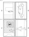
- FIG. 2 is an explanatory diagram that shows an example of a reduced image (reduced image 32).
- the reduced image 32 includes all the regions included in a frame image.
- regions 40 shown in FIG. 2 are regions corresponding to cropped regions, which will be described below.
- the regions corresponding to cropped regions will be described as regions 40 in the reduced image 32.
- FIG. 3 is an explanatory diagram that shows an example of a plurality of cropped images (a set 52 of cropped images 50) generated from one frame image. While the cropped images 50 have a resolution the same as that of the frame image, each of the cropped images 50 only include a part of the region within the frame image, such as shown in FIG. 3 . Accordingly, the camera 10 according to the present embodiment basically generates one reduced image, and one or more cropped images, from one frame image. According to this generation example, a user can confirm a full view photographed by the camera 10, and a user can confirm a region of an attention target with a high resolution. Also, the total data amount can be suppressed compared to that of the frame image.
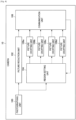
- the camera 10 includes a photographing unit 100, a picture reduction unit 102, a region setting unit 104, a plurality of picture cropping units 106, and a communication unit 108.
- a photographing unit 100 includes a photographing unit 100, a picture reduction unit 102, a region setting unit 104, a plurality of picture cropping units 106, and a communication unit 108.
- a communication unit 108 includes a communication unit 108.
- FIG. 4 where four picture cropping units 106 are included, it is not limited to such an example, and may include an arbitrary number of one or more.
- the photographing unit 100 has a function that acquires a frame image, by forming an external picture on an imaging element such as a Charge Coupled Device (CCD) or a Complementary Metal Oxide Semiconductor (CMOS), for example, through a lens.
- an imaging element such as a Charge Coupled Device (CCD) or a Complementary Metal Oxide Semiconductor (CMOS), for example, through a lens.
- CCD Charge Coupled Device
- CMOS Complementary Metal Oxide Semiconductor
- the picture reduction unit 102 generates a reduced image by reducing the frame image acquired by the photographing unit 100 to a prescribed size.
- the region setting unit 104 sets cropped regions, which are regions that become a generation source of cropped images, in the frame image acquired by the photographing unit 100. For example, the region setting unit 104 sets cropped regions only of the number of picture cropping units 106 included in the camera 10, from the frame image acquired by the photographing unit 100.
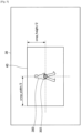
- FIG. 5 is an explanatory diagram that shows a setting example of a cropped region by the region setting unit 104. Note that, in FIG. 5 , the length of a horizontal width of the cropped region 40 is described as "crop_width”, and the length of a vertical width of the cropped region 40 is described as “crop_height”.
- the region setting unit 104 detects an object of a detection target such as a person 300 from within the frame image 30, and sets the cropped region 40 based on a detection position 302 of the object.
- the picture cropping unit 106 is an example of a segmented image generation unit in an embodiment of the present disclosure.
- the picture cropping unit 106 generates a cropped image by segmenting the cropped region set by the region setting unit 104 from the frame image acquired by the photographing unit 100.
- the picture cropping unit 106a generates a cropped image 50a from a cropped region corresponding to the region 40a shown in FIG. 2 , set by the region setting unit 104.
- the picture cropping unit 106b generates a cropped image 50b from a cropped region corresponding to the region 40b shown in FIG. 2 , set by the region setting unit 104.
- the communication unit 108 is an example of an acquisition unit according to the present embodiment.
- the communication unit 108 performs transmission and reception of various types of information between apparatuses connected to the communication network 24, via the communication network 24, which will be described below.
- the communication unit 108 transmits, to the storage 20, the reduced image acquired by the picture reduction unit 102, and the plurality of cropped images generated by the plurality of picture cropping units 106.
- the communication unit 108 receives, from the monitoring terminal 22, detection specification information for selecting a cropping target, set by a user.
- detection specification information may be stored from the beginning by the camera 10, instead of being received from the monitoring terminal 22.
- detection specification information may be stored from the beginning by the camera 10, instead of being received from the monitoring terminal 22.
- a description will be made by centering on an example where detection specification information is received from the monitoring terminal 22.
- the storage 20 is a storage apparatus for storing the reduced image and cropped images received from the camera 10.
- the storage 20 associates and stores identification information of the camera 10, and at the time of photographing, the received reduced image, and the received plurality of cropped images.
- the storage 20 can be set, for example, to a data center, a monitoring center where monitoring staff are employed or the like.
- the monitoring terminal 22 is an information processing terminal for displaying the reduced image and cropped images generated by the camera 10.
- This monitoring terminal 22 can be set, for example, in a monitoring center, and can be used by monitoring staff.
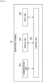
- FIG. 6 is a function block diagram that shows a configuration of the monitoring terminal 22 according to the present embodiment.
- the monitoring terminal 22 has a control unit 220, a communication unit 222, a display unit 224, and an input unit 226.
- the control unit 220 generally controls the operations of the monitoring terminal 22, by using hardware such as a Central Processing Unit (CPU), a Random Access Memory (RAM), and a Read Only Memory (ROM) built into the monitoring terminal 22.
- CPU Central Processing Unit
- RAM Random Access Memory
- ROM Read Only Memory
- the communication unit 222 performs transmission and reception of various types of information between apparatuses connected to the communication network 24, via the communication network 24, which will be described below.
- the communication unit 222 receives, from the storage 20, the reduced image and cropped images stored in the storage 20.
- the communication unit 222 it is possible for the communication unit 222 to directly receive, from the camera 10, the reduced image and plurality of cropped images generated by the camera 10.
- the communication unit 222 transmits, to the camera 10, detection specification information for selecting an object of a cropping target, input by a user on an evaluation standard setting screen, which will be described below, in accordance with a control of the control unit 220.
- the display unit 224 is constituted, for example, by a display such as a Liquid Crystal Display (LCD), or an Organic Light Emitting Diode (OLED).
- This display unit 224 displays, for example, a monitoring screen that includes the reduced image or cropped images received from the storage 20.
- the display unit 224 displays an evaluation standard setting screen, in accordance with a control of the control unit 220.
- This evaluation standard setting screen is a screen for a user to set (or change) detection specification information used for determining an object of a cropping target from within a frame image photographed by the camera 10.
- detection specification information is set so as to include one or more evaluation items selected on the evaluation standard setting screen, and evaluation standards of these evaluation items.
- the evaluation standard setting screen 60 includes, for example, setting columns 600 of a plurality of evaluation items such as an object size setting column 600a, and an object speed setting column 600b.
- the plurality of evaluation items includes, for example, an object size, an object speed, an object staying time, an object aspect ratio, a predicted time up until an object goes outside the screen, a distance between an object and a home position, an object tracking time, an object stopping time or the like.
- an object aspect ratio is an evaluation item used for distinguishing an object type of a detection target, such as distinguishing between a person and a vehicle, for example. Note that, being able to identify an object type with a low calculation amount can be included as an advantage of using an aspect ratio.
- a predicted time up until an object goes outside the screen is a time at which an object movement speed is calculated based on a change of position in a past frame, for example, and is predicted based on the calculated movement speed.
- This "predicted time up until an object goes outside the screen" is an evaluation item used in the case where photographing at least one time, for example, even if it is an object moving at a high speed.
- a home position is an example of a monitoring target region in an embodiment of the present disclosure. This home position is determined, for example, for each detection frame of an object.
- a detection frame can be determined, for example, for each location where a user desires to monitor such as a passage, a building entrance, or a restricted region.
- a detection frame of an object may be set in association with each of the plurality of picture cropping units 106 included in the camera 10.
- FIG. 7 shows an object speed, an object aspect ratio, a distance up to a home position, and an object stopping time selected as evaluation items by a user.
- FIG. 7 shows evaluation standards specified so that an evaluation becomes higher, such as an object with an object speed faster than a stipulated value, an object with an object aspect ratio smaller than a stipulated value, an object with a distance up to a home position longer than a stipulated value, or an object with an object stopping time shorter than a stipulated value.
- the input unit 226 includes, for example, an input apparatus such as a mouse, a keyboard, a touch panel, or a microphone. This input unit 226 receives various types of inputs by a user to the monitoring terminal 22. For example, the input unit 226 receives an input of detection specification information to the evaluation standard setting screen displayed in the display unit 224.
- the communication network 24 is a wired or wireless transmission path of information transmitted from apparatuses connected to the communication network 24.
- the communication network 24 may include a public line network such as a telephone line network, the Internet, or a satellite communication network, or various types of Local Area Networks (LAN), Wide Area Networks (WAN) or the like that include an Ethernet (registered trademark).
- the communication network 24 may include a dedicated line network such as an Internet Protocol-Virtual Private Network (IP-VPN).
- IP-VPN Internet Protocol-Virtual Private Network
- the image processing system according to the present embodiment is not limited to the above described configuration.
- the storage 20 and the monitoring terminal 22 may be integrally constituted.
- the camera 10 it is possible for the camera 10 according to the present embodiment to automatically select the most suitable cropping target, based on detection specification information specified by a user.
- the features of the configuration of the camera 10 according to the present embodiment are related, in particular, to the configuration of the region setting unit 104.
- a configuration of the region setting unit 104 will be additionally described in detail by referring to FIG. 8 .
- the region setting unit 104 includes an object detection unit 120, a cropped region determination unit 122, and an overlapping decision unit 124.
- the object detection unit 120 detects an object of a cropping target from within a detection frame in a frame image (hereinafter, called a present frame image) acquired by the photographing unit 100, for example, based on detection specification information received from the monitoring terminal 22. For example, the object detection unit 120 detects, as a cropping target, an object with the highest value evaluated by an evaluation standard of an evaluation item included in the received detection specification information, from among a plurality of objects included in a detection frame.
- the object detection unit 120 detects an object of a cropping target based on a combination of evaluation values by the evaluation standards of each of the plurality of evaluation items included in this detection specification information, from among a plurality of objects included in a detection frame. For example, in the above described case, the object detection unit 120 first performs an evaluation for each of a plurality of objects included in a detection frame, in accordance with the evaluation standards for each of the plurality of evaluation items shown by this detection specification information, and calculates a total of the evaluation values of each evaluation item. Then, the object detection unit 120 detects, as a cropping target, an object with the highest total of the evaluation values of each evaluation item.
- the object detection unit 120 decides whether or not to switch an object of a detection target, based on a comparison between the length of time that the present object of a detection target is estimated to have stopped, and a stopping upper limit time included in this detection specification information.
- the object detection unit 120 decides to switch an object of a detection target to another object. Further, in the case where the length of time that the present object of a detection target is estimated to have stopped is smaller than a stopping upper limit time, the object detection unit 120 decides to set an object of a detection target the same as in the previous frame image. Note that, in the case where a change amount of a detection position of an object of a detection target between consecutive frame images is within a prescribed range, for example, it is possible for the object detection unit 120 to estimate that this object is stopped.
- the object detection unit 120 decides whether or not to switch an object of a detection target, based on a comparison between a continuation time of the detection of the present object of a detection target, and a tracking upper limit time included in this detection specification information.
- a tracking upper limit time is an upper limit value of time to maintain an object of a cropping target to a same object.
- the object detection unit 120 decides to switch an object of a detection target to another object. Further, in the case where a continuation time of the detection of the present object of a detection target is a tracking upper limit time or less, the object detection unit 120 decides to set an object of a detection target the same as in the previous frame image.
- the object detection unit 120 decides whether or not to switch an object of a detection target, based on a comparison between a distance between a home position set beforehand in a moving image and the present object of a detection target, and a monitoring upper limit distance included in this detection specification information.
- the object detection unit 120 decides to switch an object of a detection target to another object, such as an object positioned closest to the home position, for example. Further, in the case where a distance between the home position and the present object of a detection target is within a monitoring upper limit distance, the object detection unit 120 decides to set an object of a detection target the same as in the previous frame image.
- the object detection unit 120 decides to switch an object of a cropping target of any of the decided cropped regions to another object.
- the object detection unit 120 decides to switch an object of a cropping target of any of the overlapping cropped regions to another object.
- the object detection unit 120 may decide a cropped region for which an object of a cropping target is to be switched to another object (hereinafter, called a cropping target switching region), from among the cropped regions for which it has been decided that the cropped regions are overlapping by the overlapping decision unit 124, in accordance with the received detection specification information. For example, the object detection unit 120 may determine a cropped region, which includes a cropping target with a low value of an evaluation item included in the received detection specification information, from among the overlapping cropped regions, to be a cropping target switching region. Further, the object detection unit 120 may determine a cropped region, for which the detection (tracking) of an object of a cropping target is continuing from an earlier time, from among the overlapping cropped regions, to be a cropping target switching region.
- a cropping target switching region another object
- the object detection unit 120 it is possible for the object detection unit 120 to detect a prescribed number of objects, such as a number within the number of picture cropping units 106, for example, from within the present frame image.
- the object detection unit 120 may not detect any objects.
- the cropped region determination unit 122 is an example of a segmented region determination unit in an embodiment of the present disclosure.
- the cropped region determination unit 122 determines a cropped region in the present frame image, so that a detection position of an object detected by the object detection unit 120 is included.
- the cropped region determination unit 122 determines a cropped region in the present frame image, so that a detection position of an object detected by the object detection unit 120 becomes the center of the cropped region.
- the shape and size of the cropped region in the frame image is basically determined the same in all of the frame images. Further, the size of the cropped region is basically determined to a predetermined size.
- the cropped region determination unit 122 may determine not to output any region. Or, in the above described case, the cropped region determination unit 122 may determine a region that includes a home position as a cropped region.
- the overlapping decision unit 124 decides whether or not this cropped region is overlapping with another cropped region, based on an overlapping decision condition included in the received detection specification information. For example, in the case where the ratio of the area of an overlapping region is a prescribed threshold or more, with respect to the area of the cropped region, the overlapping decision unit 124 decides that this cropped region is overlapping with the other cropped region. Further, in the case where a distance from the center of this cropped region up to another cropped region is a prescribed threshold or less, the overlapping decision unit 124 decides that this cropped region is overlapping with the other cropped region.
- FIG. 9 to FIG. 11 an operation example will be described in a scene where the camera 10 has four picture cropping units 106, and one reduced image and four cropped images are generated from one frame image. Note that, this operation is repeatedly executed for each prescribed frame rate.
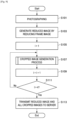
- FIG. 9 is a flow chart that shows an operation example according to the present embodiment. As shown in FIG. 9 , first the photographing unit 100 of the camera 10 acquires a frame image by photographing an external picture, when a prescribed photographing timing is reached (S101).
- the picture reduction unit 102 generates a reduced image by reducing the frame image acquired in step S101 (hereinafter, called a present frame image) to a prescribed size (S103).
- the camera 10 repeatedly performs a "cropped image generation process", which will be described below, the number of the picture cropping units 106, that is, four times (S105 to S111).
- the communication unit 108 transmits the reduced image generated in S103 and the four cropped images generated in step S107 to the storage 20 (S113).
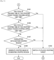
- the object detection unit 120 of the camera 10 detects an object set as an I-th placed cropping target, that is, an object being tracked (S151).
- the cropped region determination unit 122 determines a cropped region in the present frame image, so that a detection position of the object detected in S151 becomes the center of the cropped region (S153).
- the object detection unit 120 decides whether or not the total of a tracking time (from a tracking start) of the object detected in S151 has passed a tracking upper limit time (S161). In the case where the total of the object tracking time has passed a tracking upper limit time (S161: Yes), the object detection unit 120 switches the I-th placed cropping target to another object (S163). Afterwards, the camera 10 again performs the operation of S153.
- next the object detection unit 120 decides whether or not the total of a stopping time (from the time when a stop has been detected) of the object detected in S151 has passed a stopping upper limit time (S165). In the case where the total of the object stopping time has passed a stopping upper limit time (S165: Yes), the object detection unit 120 performs the operation of S163.
- the overlapping decision unit 124 decides whether or not the cropped region determined in S153 is overlapping with another cropped region within the same frame image (S167). In the case where this cropped region is overlapping with another cropped region (S167: Yes), the object detection unit 120 performs the operation of S163.
- the picture cropping unit 106 generates a cropped image, by segmenting this cropped region from the present frame image (S169).
- the camera 10 detects an object based on an evaluation item selected by a user from among a plurality of evaluation items, and determines a cropped region in the present frame image, so that a detection position of the detected object is included. Accordingly, the most suitable cropping target can be automatically selected, from among a plurality of objects included in the frame image. Further, an object of a cropping target can be similarly optimized with respect to the length of time to be cropped.
- the camera 10 switches an object of a cropping target to another object, and determines a cropped region so that the object after switching becomes the center. Accordingly, even if an object determined once to be a cropping target continues to be positioned at the same location, an object of a cropping target is changed to another object, if a stopping condition time has passed. Therefore, the same location continuing to be set to a segmented region for a long time can be prevented.
- the camera 10 can perform the generation of a cropped image in real time.
- the present embodiment it is possible to generate a reduced image and cropped images only with the camera 10 unit. Accordingly, since it may not be necessary for the camera 10 to transmit a frame image to another apparatus such as a server, for example, for generating a reduced image and cropped images, the communication amount can be reduced.
- the image processing apparatus according to an embodiment of the present disclosure is the camera 10, it is not limited to such an example.
- the image processing apparatus according to the present embodiment may be the monitoring terminal 22.
- the image processing apparatus may be the server.
- this server and the storage 20 may be integrally constituted.
- a tracking upper limit time of an object, and a stopping upper limit time of an object are values included in detection specification information, that is, are fixed values, it is not limited to such an example, and the camera 10 may dynamically determine a tracking upper limit time, or a stopping upper limit time.
- the camera 10 may dynamically determine a tracking upper limit time, or a stopping upper limit time, for each detection frame.
- the camera 10 may make a tracking upper limit time longer as the number of untracked objects decreases, for each detection frame.
- a monitoring target region is included, for example, in a detection frame, the camera 10 may make a tracking upper limit time longer.
- a computer program for causing hardware such as a CPU, a ROM, and a RAM, for example, to exhibit functions the same as the above described picture reduction unit 102, region setting unit 104, and picture cropping unit 106 can be provided. Further, a recording medium to which this computer program is recorded can also be provided.
Landscapes
- Engineering & Computer Science (AREA)
- Physics & Mathematics (AREA)
- General Physics & Mathematics (AREA)
- Theoretical Computer Science (AREA)
- Multimedia (AREA)
- Computer Vision & Pattern Recognition (AREA)
- Health & Medical Sciences (AREA)
- General Health & Medical Sciences (AREA)
- Psychiatry (AREA)
- Social Psychology (AREA)
- Human Computer Interaction (AREA)
- Studio Devices (AREA)
- Image Analysis (AREA)
- Image Processing (AREA)
- Closed-Circuit Television Systems (AREA)
Claims (14)
- Informationsverarbeitungsvorrichtung, umfassend:
Schaltungsanordnung (100, 120), die für folgende Vorgänge ausgelegt ist:Erzeugen oder Empfangen eines ersten Bildes und eines zweiten Bildes, das vor dem ersten Bild einer Sequenz von Bildern aufgenommen wurde, beinhaltend ein Objekt, das als das Zielobjekt im zweiten Bild identifiziert wird, Bestimmen, dass eine Zeitdauer von Bewegung des Objekts unter einem vorbestimmten Bewegungsschwellenwert liegt, undEntscheiden, ob das zu identifizierende Zielobjekt auf ein anderes Objekt im ersten Bild umgeschaltet werden soll, auf der Grundlage der bestimmten Zeitdauer, in der die Bewegung des Objekts unter dem vorbestimmten Bewegungsschwellenwert liegt, und einer Zeitdauer, in der das Objekt als das Zielobjekt identifiziert wird. - Informationsverarbeitungsvorrichtung nach Anspruch 1, wobei die Schaltungsanordnung dafür ausgelegt ist, das Zielobjekt vom Objekt zu einem anderen Objekt zu wechseln, das im ersten Bild beinhaltet ist, wenn die Schaltungsanordnung bestimmt, das Objekt nicht mehr als Zielobjekt zu identifizieren.
- Informationsverarbeitungsvorrichtung nach Anspruch 1, wobei die Schaltungsanordnung für folgende Vorgänge ausgelegt ist:Bestimmen, ob die Zeitdauer, in der die Bewegung des Objekts unter dem vorbestimmten Bewegungsschwellenwert liegt, eine obere Zeitgrenze überschreitet, undIdentifizieren des Objekts als das Zielobjekt, wenn die Zeitdauer, in der die Bewegung des Objekts unter dem vorbestimmten Bewegungsschwellenwert liegt, kleiner oder gleich der oberen Zeitgrenze ist.
- Informationsverarbeitungsvorrichtung nach Anspruch 1, wobei die Schaltungsanordnung für folgende Vorgänge ausgelegt ist:Bestimmen, ob die Zeitdauer, in der die Bewegung des Objekts unter dem vorbestimmten Bewegungsschwellenwert liegt, eine obere Zeitgrenze überschreitet, undIdentifizieren eines anderen Objekts, das im ersten Bild beinhaltet ist, als das Zielobjekt, wenn die Zeitdauer, in der die Bewegung des Objekts unter dem vorbestimmten Bewegungsschwellenwert liegt, die obere Zeitgrenze überschreitet.
- Informationsverarbeitungsvorrichtung nach Anspruch 1, wobeidas Zielobjekt ein Ausschnittsziel ist, unddie Schaltungsanordnung dafür ausgelegt ist, ein ausgeschnittenes Bild zu erzeugen, indem sie das erste Bild auf der Grundlage einer Position des Objekts innerhalb des ersten Bildes beschneidet, wenn das Objekt als das Zielobjekt identifiziert ist.
- Informationsverarbeitungsvorrichtung nach Anspruch 1, wobeidie Schaltungsanordnung dafür ausgelegt ist, eine Vielzahl von Bildströmen zu übertragen,die Vielzahl von Bildströmen ausgeschnittene Bilder von verschiedenen Abschnitten jeder Sequenz von Bildern beinhalten und jeder der verschiedenen Abschnitte einem anderen Objekt entspricht.
- Informationsverarbeitungsvorrichtung nach Anspruch 6, wobei die Schaltungsanordnung für folgende Vorgänge ausgelegt ist:Erzeugen einer Version des ersten Bildes mit geringerer Auflösung, undÜbertragen des ausgeschnittenen Bildes und der Version des ersten Bildes mit geringerer Auflösung.
- Informationsverarbeitungsvorrichtung nach Anspruch 1, wobei die Schaltungsanordnung für folgende Vorgänge ausgelegt ist:Festlegen einer obere Zeitgrenze auf der Grundlage einer Benutzereingabe; undIdentifizieren des Objekts als das Zielobjekt auf der Grundlage eines Vergleichs der Zeitdauer, in der die Bewegung des Objekts unter dem vorbestimmten Bewegungsschwellenwert liegt, mit der festgelegten oberen Zeitgrenze.
- Informationsverarbeitungsvorrichtung nach Anspruch 1, wobei die Schaltungsanordnung für folgende Vorgänge ausgelegt ist:Festlegen unterschiedlicher oberer Zeitgrenzen für verschiedene Bilder, einschließlich des ersten Bildes, in der Sequenz von Bildern, undIdentifizieren des Objekts als das Zielobjekt im ersten Bild auf der Grundlage eines Vergleichs der Zeitdauer, in der die Bewegung des Objekts unter dem vorbestimmten Bewegungsschwellenwert liegt, und der für das erste Bild festgelegten oberen Zeitgrenze.
- Informationsverarbeitungsvorrichtung nach Anspruch 1, wobei die Schaltungsanordnung für folgende Vorgänge ausgelegt ist:Erfassen einer Vielzahl von Objekten, die im ersten Bild beinhaltet sind, undIdentifizieren einer Teilmenge der Vielzahl von Objekten als Zielobjekte im ersten Bild, wenn eine Anzahl der Vielzahl von Objekten eine vorbestimmte maximale Anzahl von Zielobjekten überschreitet, wobei die vorbestimmte maximale Anzahl größer als 1 ist.
- Informationsverarbeitungsvorrichtung nach Anspruch 1, wobei die Schaltungsanordnung für folgende Vorgänge ausgelegt ist:
Fortsetzen des Identifizierens des Objekts als das Zielobjekt in nachfolgenden aufeinanderfolgenden Bildern der Sequenz von Bildern, die das Objekt beinhalten und nach dem ersten Bild aufgenommen wurden, bis die Zeitdauer der Bewegung des Objekts, in der die Bewegung des Objekts unter dem vorbestimmten Bewegungsschwellenwert liegt, eine obere Zeitgrenze überschreitet. - Informationsverarbeitungsvorrichtung nach Anspruch 1, wobei die Schaltungsanordnung für folgende Vorgänge ausgelegt ist:Bestimmen einer Vielzahl von ausgeschnittenen Bereichen des ersten Bildes, wobei jedes der ausgeschnittenen Bilder einem anderen Zielobjekt entspricht, undBestimmen, ob sich ein erster der Vielzahl von ausgeschnittenen Bereichen mit einem zweiten der Vielzahl von ausgeschnittenen Bereichen überschneidet.Bestimmen, dass der erste der Vielzahl von ausgeschnittenen Bereichen mit dem zweiten der Vielzahl von ausgeschnittenen Bereichen überlappt, wenn eine Fläche eines überlappenden Bereichs für den ersten der Vielzahl von ausgeschnittenen Bereichen und den zweiten der Vielzahl von ausgeschnittenen Bereichen einen ersten vorbestimmten Überlappungsschwellenwert überschreitet oder ein Abstand zwischen den Mittelpunkten des ersten der Vielzahl von ausgeschnittenen Bereichen und des zweiten der Vielzahl von ausgeschnittenen Bereichen einen zweiten vorbestimmten Überlappungsschwellenwert überschreitet.
- Verfahren einer Informationsverarbeitungsvorrichtung zum Identifizieren eines Zielobjekts, wobei das Verfahren umfasst:Erzeugen oder Empfangen eines ersten Bildes und eines zweiten Bildes, das vor dem ersten Bild einer Sequenz von Bildern aufgenommen wurde, beinhaltend ein Objekt, das als das Zielobjekt im zweiten Bild identifiziert wird;Bestimmen, durch eine Schaltungsanordnung (100, 200) der Informationsverarbeitungsvorrichtung, einer Zeitdauer, in der Bewegung des Objekts unter dem vorbestimmten Bewegungsschwellenwert liegt, undEntscheiden, durch die Schaltungsanordnung, ob das zu identifizierende Zielobjekt auf ein anderes Objekt im ersten Bild umgeschaltet werden soll, auf der Grundlage der bestimmten Zeitdauer, in der die Bewegung des Objekts unter dem vorbestimmten Bewegungsschwellenwert liegt, und einer Zeitdauer, in der das Objekt als das Zielobjekt identifiziert wird.
- Nichtflüchtiges, computerlesbares Medium, auf dem Anweisungen gespeichert sind, die bei ihrer Ausführung durch einen Computer den Computer veranlassen, ein Verfahren für eine Informationsverarbeitungsvorrichtung zum Identifizieren eines Zielobjekts durchzuführen, wobei das Verfahren umfasst:Erzeugen oder Empfangen eines ersten Bildes und eines zweiten Bildes, das vor dem ersten Bild einer Sequenz von Bildern aufgenommen wurde, beinhaltend ein Objekt, das als das Zielobjekt im zweiten Bild identifiziert wird; Bestimmen, dass eine Zeitdauer einer Bewegung des Objekts unter dem vorbestimmten Bewegungsschwellenwert liegt, undEntscheiden, ob das zu identifizierende Zielobjekt auf ein anderes Objekt im ersten Bild umgeschaltet werden soll, auf der Grundlage der bestimmten Zeitdauer, in der die Bewegung des Objekts unter dem vorbestimmten Bewegungsschwellenwert liegt, und einer Zeitdauer, in der das Objekt als das Zielobjekt identifiziert wird.
Applications Claiming Priority (2)
| Application Number | Priority Date | Filing Date | Title |
|---|---|---|---|
| JP2015082275A JP6604019B2 (ja) | 2015-04-14 | 2015-04-14 | 画像処理装置、画像処理方法、および画像処理システム |
| PCT/JP2016/001897 WO2016166950A1 (en) | 2015-04-14 | 2016-04-04 | Image processing apparatus, image processing method, and image processing system |
Publications (2)
| Publication Number | Publication Date |
|---|---|
| EP3284014A1 EP3284014A1 (de) | 2018-02-21 |
| EP3284014B1 true EP3284014B1 (de) | 2023-10-04 |
Family
ID=55808811
Family Applications (1)
| Application Number | Title | Priority Date | Filing Date |
|---|---|---|---|
| EP16718488.6A Active EP3284014B1 (de) | 2015-04-14 | 2016-04-04 | Bildverarbeitungsvorrichtung, bildverarbeitungsverfahren und bildverarbeitungssystem |
Country Status (5)
| Country | Link |
|---|---|
| US (1) | US10319099B2 (de) |
| EP (1) | EP3284014B1 (de) |
| JP (1) | JP6604019B2 (de) |
| CN (1) | CN107408300A (de) |
| WO (1) | WO2016166950A1 (de) |
Families Citing this family (28)
| Publication number | Priority date | Publication date | Assignee | Title |
|---|---|---|---|---|
| JP6587995B2 (ja) * | 2016-09-16 | 2019-10-09 | 富士フイルム株式会社 | 画像表示制御システム,画像表示制御方法および画像表示制御プログラム |
| JP6936018B2 (ja) | 2017-02-21 | 2021-09-15 | ソニーセミコンダクタソリューションズ株式会社 | 映像送信装置および映像受信装置 |
| US10614688B1 (en) * | 2017-03-01 | 2020-04-07 | Sunflower Labs Inc. | Detecting and identifying activities and events within a property's security perimeter using a configurable network of vibration and motion sensors |
| KR102509132B1 (ko) | 2017-06-09 | 2023-03-13 | 소니 세미컨덕터 솔루션즈 가부시키가이샤 | 영상 송신 장치 및 영상 수신 장치 |
| DE102017215079A1 (de) * | 2017-08-29 | 2019-02-28 | Osram Gmbh | Erfassen von Verkehrsteilnehmern auf einem Verkehrsweg |
| JP7007160B2 (ja) | 2017-11-10 | 2022-01-24 | ソニーセミコンダクタソリューションズ株式会社 | 送信装置 |
| EP3709662B1 (de) | 2017-11-10 | 2025-05-21 | Sony Semiconductor Solutions Corporation | Übertragungsvorrichtung |
| JP6572500B1 (ja) * | 2018-03-14 | 2019-09-11 | エスゼット ディージェイアイ テクノロジー カンパニー リミテッドSz Dji Technology Co.,Ltd | 画像処理装置、撮像装置、移動体、画像処理方法、及びプログラム |
| CN108566512A (zh) * | 2018-03-21 | 2018-09-21 | 珠海市魅族科技有限公司 | 一种智能拍摄方法、装置、计算机设备及可读存储介质 |
| EP3780629A1 (de) | 2018-04-05 | 2021-02-17 | Sony Semiconductor Solutions Corporation | Sendevorrichtung, empfangsvorrichtung und kommunikationssystem |
| JP6973258B2 (ja) * | 2018-04-13 | 2021-11-24 | オムロン株式会社 | 画像解析装置、方法およびプログラム |
| US11587292B2 (en) * | 2018-07-30 | 2023-02-21 | Disney Enterprises, Inc. | Triggered virtual reality and augmented reality events in video streams |
| JP7484103B2 (ja) * | 2018-07-31 | 2024-05-16 | 株式会社リコー | 通信端末、通信システム、通信方法、及びプログラム |
| US11528429B2 (en) | 2018-09-12 | 2022-12-13 | Sony Corporation | Image processing device, and image processing method |
| JP7584412B2 (ja) | 2019-06-28 | 2024-11-15 | ソニーセミコンダクタソリューションズ株式会社 | 送信装置、受信装置及び伝送システム |
| WO2020261816A1 (ja) | 2019-06-28 | 2020-12-30 | ソニーセミコンダクタソリューションズ株式会社 | 送信装置、受信装置及び伝送システム |
| EP3993390A4 (de) | 2019-06-28 | 2022-08-31 | Sony Semiconductor Solutions Corporation | Sendevorrichtung, empfangsvorrichtung und kommunikationssystem |
| CN114009007A (zh) | 2019-06-28 | 2022-02-01 | 索尼半导体解决方案公司 | 发送装置、接收装置和传输系统 |
| TW202107892A (zh) | 2019-07-31 | 2021-02-16 | 日商索尼半導體解決方案公司 | 發送裝置、接收裝置及通信系統 |
| TWI749365B (zh) * | 2019-09-06 | 2021-12-11 | 瑞昱半導體股份有限公司 | 移動影像整合方法及移動影像整合系統 |
| CN112954267B (zh) * | 2019-12-11 | 2023-02-07 | 杭州海康威视数字技术股份有限公司 | 一种用于生成报警视频的摄像机 |
| JP7513639B2 (ja) * | 2020-01-30 | 2024-07-09 | 富士フイルム株式会社 | 表示方法 |
| JP7394151B2 (ja) * | 2020-01-30 | 2023-12-07 | 富士フイルム株式会社 | 表示方法 |
| CN115362688A (zh) | 2020-03-25 | 2022-11-18 | 索尼半导体解决方案公司 | 接收装置和传输系统 |
| WO2021199944A1 (ja) | 2020-03-31 | 2021-10-07 | ソニーセミコンダクタソリューションズ株式会社 | 送信装置、受信装置及び伝送システム |
| US12008881B1 (en) * | 2021-05-28 | 2024-06-11 | Swamcam LLC | Water safety device, system, and method |
| JP7690940B2 (ja) * | 2022-10-24 | 2025-06-11 | トヨタ自動車株式会社 | 情報処理システム及び情報処理システムの処理方法 |
| CN119450187A (zh) * | 2023-07-31 | 2025-02-14 | 北京小米移动软件有限公司 | 拍摄方法、装置、电子设备及介质 |
Family Cites Families (29)
| Publication number | Priority date | Publication date | Assignee | Title |
|---|---|---|---|---|
| JP4516665B2 (ja) | 2000-05-19 | 2010-08-04 | パナソニック株式会社 | 監視装置 |
| JP2002092600A (ja) * | 2000-09-19 | 2002-03-29 | Oki Electric Ind Co Ltd | 道路監視装置 |
| JP4421121B2 (ja) * | 2001-02-06 | 2010-02-24 | 株式会社日立国際電気 | 侵入物体検出方法 |
| JP3782368B2 (ja) * | 2002-03-29 | 2006-06-07 | 株式会社東芝 | 物体画像切り出し方法及びプログラム並びに物体画像切り出し装置 |
| JP4186693B2 (ja) | 2003-05-08 | 2008-11-26 | 日本電信電話株式会社 | 部分情報抽出方法及び映像切り出し方法及び映像表示方法及び映像出力方法及び装置及びプログラム及び映像出力プログラムを格納した記憶媒体 |
| US7171024B2 (en) | 2003-12-01 | 2007-01-30 | Brickstream Corporation | Systems and methods for determining if objects are in a queue |
| US7801328B2 (en) * | 2005-03-31 | 2010-09-21 | Honeywell International Inc. | Methods for defining, detecting, analyzing, indexing and retrieving events using video image processing |
| JP5040258B2 (ja) * | 2006-10-23 | 2012-10-03 | 株式会社日立製作所 | 映像監視装置、映像監視システムおよび画像処理方法 |
| JP5111088B2 (ja) * | 2007-12-14 | 2012-12-26 | 三洋電機株式会社 | 撮像装置及び画像再生装置 |
| US8284249B2 (en) | 2008-03-25 | 2012-10-09 | International Business Machines Corporation | Real time processing of video frames for triggering an alert |
| US20100289904A1 (en) * | 2009-05-15 | 2010-11-18 | Microsoft Corporation | Video capture device providing multiple resolution video feeds |
| US8724928B2 (en) * | 2009-08-31 | 2014-05-13 | Intellectual Ventures Fund 83 Llc | Using captured high and low resolution images |
| CN102063610B (zh) * | 2009-11-13 | 2013-08-28 | 鸿富锦精密工业(深圳)有限公司 | 影像辨识系统及方法 |
| US10645344B2 (en) * | 2010-09-10 | 2020-05-05 | Avigilion Analytics Corporation | Video system with intelligent visual display |
| TWI514324B (zh) * | 2010-11-30 | 2015-12-21 | Ind Tech Res Inst | 影像目標區域追蹤系統與方法及電腦程式產品 |
| US8879789B1 (en) | 2011-01-20 | 2014-11-04 | Verint Americas Inc. | Object analysis using motion history |
| US9111352B2 (en) * | 2011-12-27 | 2015-08-18 | Avid Technology, Inc. | Automated detection and correction of stereoscopic edge violations |
| JP2013172446A (ja) * | 2012-02-23 | 2013-09-02 | Sony Corp | 情報処理装置、端末装置、撮像装置、情報処理方法、及び撮像装置における情報提供方法 |
| JP2013232869A (ja) * | 2012-05-02 | 2013-11-14 | Olympus Corp | 撮像装置 |
| US9171382B2 (en) | 2012-08-06 | 2015-10-27 | Cloudparc, Inc. | Tracking speeding violations and controlling use of parking spaces using cameras |
| JP2014053859A (ja) * | 2012-09-10 | 2014-03-20 | Canon Inc | 移動体観測装置 |
| KR101791604B1 (ko) * | 2012-09-11 | 2017-10-30 | 삼성전자주식회사 | 헤드 포지션 추정 방법 및 장치, 컴퓨터 판독가능 저장 매체 |
| CN103020989B (zh) * | 2012-12-05 | 2016-06-08 | 河海大学 | 一种基于在线场景特征聚类的多视角目标跟踪方法 |
| CN105075248A (zh) | 2013-03-29 | 2015-11-18 | 日本电气株式会社 | 对象物体标识设备、对象物体标识方法和对象物体标识程序 |
| JP2014222825A (ja) * | 2013-05-13 | 2014-11-27 | キヤノン株式会社 | 映像処理装置および映像処理方法 |
| US9251431B2 (en) * | 2014-05-30 | 2016-02-02 | Apple Inc. | Object-of-interest detection and recognition with split, full-resolution image processing pipeline |
| US9449239B2 (en) * | 2014-05-30 | 2016-09-20 | Apple Inc. | Credit card auto-fill |
| US20150347860A1 (en) * | 2014-05-30 | 2015-12-03 | Apple Inc. | Systems And Methods For Character Sequence Recognition With No Explicit Segmentation |
| WO2015193877A1 (en) * | 2014-06-18 | 2015-12-23 | Trax Technology Solutions Pte. Ltd. | A method and a system for object recognition |
-
2015
- 2015-04-14 JP JP2015082275A patent/JP6604019B2/ja active Active
-
2016
- 2016-04-04 EP EP16718488.6A patent/EP3284014B1/de active Active
- 2016-04-04 CN CN201680019676.2A patent/CN107408300A/zh active Pending
- 2016-04-04 WO PCT/JP2016/001897 patent/WO2016166950A1/en not_active Ceased
- 2016-04-04 US US15/542,685 patent/US10319099B2/en active Active
Also Published As
| Publication number | Publication date |
|---|---|
| US20170372485A1 (en) | 2017-12-28 |
| JP2016201756A (ja) | 2016-12-01 |
| WO2016166950A1 (en) | 2016-10-20 |
| EP3284014A1 (de) | 2018-02-21 |
| JP6604019B2 (ja) | 2019-11-13 |
| US10319099B2 (en) | 2019-06-11 |
| CN107408300A (zh) | 2017-11-28 |
Similar Documents
| Publication | Publication Date | Title |
|---|---|---|
| EP3284014B1 (de) | Bildverarbeitungsvorrichtung, bildverarbeitungsverfahren und bildverarbeitungssystem | |
| EP3285477B1 (de) | Bildverarbeitungsvorrichtung, bildverarbeitungsverfahren und bildverarbeitungssystem | |
| EP3979200A1 (de) | Verfahren und vorrichtung zur verfolgung von videozielen, computervorrichtung und speichermedium | |
| US10346685B2 (en) | System and method for detecting and tracking a moving object | |
| US10607088B2 (en) | Image processing device, image processing method, and image processing system | |
| CN110472599B (zh) | 对象数量确定方法、装置、存储介质与电子设备 | |
| EP4035070B1 (de) | Verfahren und server zur erleichterung des trainings eines überwachten maschinenlernprozesses | |
| US20200145623A1 (en) | Method and System for Initiating a Video Stream | |
| KR101750094B1 (ko) | 영상의 실시간 모니터링을 통한 비정상 집단행동 분류 방법 | |
| US20170054897A1 (en) | Method of automatically focusing on region of interest by an electronic device | |
| CN110782433B (zh) | 基于时序的动态信息暴力抛物检测方法、装置及存储介质 | |
| CN111091098A (zh) | 检测模型的训练方法、检测方法及相关装置 | |
| US20200082544A1 (en) | Computer vision processing | |
| JP2015103104A (ja) | 情報処理装置、情報処理方法、情報処理システム | |
| Hu et al. | A novel approach for crowd video monitoring of subway platforms | |
| WO2013017184A1 (en) | Method and device for video surveillance | |
| JP6963038B2 (ja) | 画像処理装置および画像処理方法 | |
| CN114332948A (zh) | 基于yolov5算法的人头检测方法、模型训练方法和装置 | |
| JP6996538B2 (ja) | 画像処理装置、画像処理方法、および画像処理システム | |
| US20210250513A1 (en) | Method for tracking target object, storage medium and electronic device | |
| KR102107137B1 (ko) | 팬틸트줌 카메라를 이용한 이벤트 감지방법 및 장치 | |
| Zaihidee et al. | Comparison of human segmentation using thermal and color image in outdoor environment | |
| Nguyen et al. | Effectiveness of detection-based and regression-based approaches for estimating mask-wearing ratio | |
| Ercan et al. | Computer Vision Based Safety Inspection in Public Housing | |
| Tan | Medoid-shift based separation of occluded persons in thermal infrared images |
Legal Events
| Date | Code | Title | Description |
|---|---|---|---|
| STAA | Information on the status of an ep patent application or granted ep patent |
Free format text: STATUS: THE INTERNATIONAL PUBLICATION HAS BEEN MADE |
|
| PUAI | Public reference made under article 153(3) epc to a published international application that has entered the european phase |
Free format text: ORIGINAL CODE: 0009012 |
|
| STAA | Information on the status of an ep patent application or granted ep patent |
Free format text: STATUS: REQUEST FOR EXAMINATION WAS MADE |
|
| 17P | Request for examination filed |
Effective date: 20171002 |
|
| AK | Designated contracting states |
Kind code of ref document: A1 Designated state(s): AL AT BE BG CH CY CZ DE DK EE ES FI FR GB GR HR HU IE IS IT LI LT LU LV MC MK MT NL NO PL PT RO RS SE SI SK SM TR |
|
| AX | Request for extension of the european patent |
Extension state: BA ME |
|
| DAV | Request for validation of the european patent (deleted) | ||
| DAX | Request for extension of the european patent (deleted) | ||
| STAA | Information on the status of an ep patent application or granted ep patent |
Free format text: STATUS: EXAMINATION IS IN PROGRESS |
|
| 17Q | First examination report despatched |
Effective date: 20180720 |
|
| RAP3 | Party data changed (applicant data changed or rights of an application transferred) |
Owner name: SONY GROUP CORPORATION |
|
| REG | Reference to a national code |
Ref country code: DE Ref legal event code: R079 Free format text: PREVIOUS MAIN CLASS: G06K0009000000 Ipc: G06T0007200000 Ref document number: 602016083161 Country of ref document: DE |
|
| GRAP | Despatch of communication of intention to grant a patent |
Free format text: ORIGINAL CODE: EPIDOSNIGR1 |
|
| STAA | Information on the status of an ep patent application or granted ep patent |
Free format text: STATUS: GRANT OF PATENT IS INTENDED |
|
| RIC1 | Information provided on ipc code assigned before grant |
Ipc: G06V 40/20 20220101ALI20230411BHEP Ipc: G06V 20/52 20220101ALI20230411BHEP Ipc: G06T 7/20 20170101AFI20230411BHEP |
|
| INTG | Intention to grant announced |
Effective date: 20230504 |
|
| GRAS | Grant fee paid |
Free format text: ORIGINAL CODE: EPIDOSNIGR3 |
|
| GRAA | (expected) grant |
Free format text: ORIGINAL CODE: 0009210 |
|
| STAA | Information on the status of an ep patent application or granted ep patent |
Free format text: STATUS: THE PATENT HAS BEEN GRANTED |
|
| AK | Designated contracting states |
Kind code of ref document: B1 Designated state(s): AL AT BE BG CH CY CZ DE DK EE ES FI FR GB GR HR HU IE IS IT LI LT LU LV MC MK MT NL NO PL PT RO RS SE SI SK SM TR |
|
| REG | Reference to a national code |
Ref country code: GB Ref legal event code: FG4D |
|
| REG | Reference to a national code |
Ref country code: CH Ref legal event code: EP |
|
| REG | Reference to a national code |
Ref country code: DE Ref legal event code: R096 Ref document number: 602016083161 Country of ref document: DE |
|
| REG | Reference to a national code |
Ref country code: IE Ref legal event code: FG4D |
|
| REG | Reference to a national code |
Ref country code: LT Ref legal event code: MG9D |
|
| REG | Reference to a national code |
Ref country code: NL Ref legal event code: MP Effective date: 20231004 |
|
| REG | Reference to a national code |
Ref country code: AT Ref legal event code: MK05 Ref document number: 1618533 Country of ref document: AT Kind code of ref document: T Effective date: 20231004 |
|
| PG25 | Lapsed in a contracting state [announced via postgrant information from national office to epo] |
Ref country code: NL Free format text: LAPSE BECAUSE OF FAILURE TO SUBMIT A TRANSLATION OF THE DESCRIPTION OR TO PAY THE FEE WITHIN THE PRESCRIBED TIME-LIMIT Effective date: 20231004 |
|
| PG25 | Lapsed in a contracting state [announced via postgrant information from national office to epo] |
Ref country code: GR Free format text: LAPSE BECAUSE OF FAILURE TO SUBMIT A TRANSLATION OF THE DESCRIPTION OR TO PAY THE FEE WITHIN THE PRESCRIBED TIME-LIMIT Effective date: 20240105 |
|
| PG25 | Lapsed in a contracting state [announced via postgrant information from national office to epo] |
Ref country code: IS Free format text: LAPSE BECAUSE OF FAILURE TO SUBMIT A TRANSLATION OF THE DESCRIPTION OR TO PAY THE FEE WITHIN THE PRESCRIBED TIME-LIMIT Effective date: 20240204 |
|
| PG25 | Lapsed in a contracting state [announced via postgrant information from national office to epo] |
Ref country code: LT Free format text: LAPSE BECAUSE OF FAILURE TO SUBMIT A TRANSLATION OF THE DESCRIPTION OR TO PAY THE FEE WITHIN THE PRESCRIBED TIME-LIMIT Effective date: 20231004 |
|
| PG25 | Lapsed in a contracting state [announced via postgrant information from national office to epo] |
Ref country code: AT Free format text: LAPSE BECAUSE OF FAILURE TO SUBMIT A TRANSLATION OF THE DESCRIPTION OR TO PAY THE FEE WITHIN THE PRESCRIBED TIME-LIMIT Effective date: 20231004 |
|
| PG25 | Lapsed in a contracting state [announced via postgrant information from national office to epo] |
Ref country code: ES Free format text: LAPSE BECAUSE OF FAILURE TO SUBMIT A TRANSLATION OF THE DESCRIPTION OR TO PAY THE FEE WITHIN THE PRESCRIBED TIME-LIMIT Effective date: 20231004 |
|
| PG25 | Lapsed in a contracting state [announced via postgrant information from national office to epo] |
Ref country code: LT Free format text: LAPSE BECAUSE OF FAILURE TO SUBMIT A TRANSLATION OF THE DESCRIPTION OR TO PAY THE FEE WITHIN THE PRESCRIBED TIME-LIMIT Effective date: 20231004 Ref country code: IS Free format text: LAPSE BECAUSE OF FAILURE TO SUBMIT A TRANSLATION OF THE DESCRIPTION OR TO PAY THE FEE WITHIN THE PRESCRIBED TIME-LIMIT Effective date: 20240204 Ref country code: GR Free format text: LAPSE BECAUSE OF FAILURE TO SUBMIT A TRANSLATION OF THE DESCRIPTION OR TO PAY THE FEE WITHIN THE PRESCRIBED TIME-LIMIT Effective date: 20240105 Ref country code: ES Free format text: LAPSE BECAUSE OF FAILURE TO SUBMIT A TRANSLATION OF THE DESCRIPTION OR TO PAY THE FEE WITHIN THE PRESCRIBED TIME-LIMIT Effective date: 20231004 Ref country code: BG Free format text: LAPSE BECAUSE OF FAILURE TO SUBMIT A TRANSLATION OF THE DESCRIPTION OR TO PAY THE FEE WITHIN THE PRESCRIBED TIME-LIMIT Effective date: 20240104 Ref country code: AT Free format text: LAPSE BECAUSE OF FAILURE TO SUBMIT A TRANSLATION OF THE DESCRIPTION OR TO PAY THE FEE WITHIN THE PRESCRIBED TIME-LIMIT Effective date: 20231004 Ref country code: PT Free format text: LAPSE BECAUSE OF FAILURE TO SUBMIT A TRANSLATION OF THE DESCRIPTION OR TO PAY THE FEE WITHIN THE PRESCRIBED TIME-LIMIT Effective date: 20240205 |
|
| PG25 | Lapsed in a contracting state [announced via postgrant information from national office to epo] |
Ref country code: SE Free format text: LAPSE BECAUSE OF FAILURE TO SUBMIT A TRANSLATION OF THE DESCRIPTION OR TO PAY THE FEE WITHIN THE PRESCRIBED TIME-LIMIT Effective date: 20231004 Ref country code: RS Free format text: LAPSE BECAUSE OF FAILURE TO SUBMIT A TRANSLATION OF THE DESCRIPTION OR TO PAY THE FEE WITHIN THE PRESCRIBED TIME-LIMIT Effective date: 20231004 Ref country code: PL Free format text: LAPSE BECAUSE OF FAILURE TO SUBMIT A TRANSLATION OF THE DESCRIPTION OR TO PAY THE FEE WITHIN THE PRESCRIBED TIME-LIMIT Effective date: 20231004 Ref country code: NO Free format text: LAPSE BECAUSE OF FAILURE TO SUBMIT A TRANSLATION OF THE DESCRIPTION OR TO PAY THE FEE WITHIN THE PRESCRIBED TIME-LIMIT Effective date: 20240104 Ref country code: LV Free format text: LAPSE BECAUSE OF FAILURE TO SUBMIT A TRANSLATION OF THE DESCRIPTION OR TO PAY THE FEE WITHIN THE PRESCRIBED TIME-LIMIT Effective date: 20231004 Ref country code: HR Free format text: LAPSE BECAUSE OF FAILURE TO SUBMIT A TRANSLATION OF THE DESCRIPTION OR TO PAY THE FEE WITHIN THE PRESCRIBED TIME-LIMIT Effective date: 20231004 |
|
| REG | Reference to a national code |
Ref country code: DE Ref legal event code: R097 Ref document number: 602016083161 Country of ref document: DE |
|
| PG25 | Lapsed in a contracting state [announced via postgrant information from national office to epo] |
Ref country code: DK Free format text: LAPSE BECAUSE OF FAILURE TO SUBMIT A TRANSLATION OF THE DESCRIPTION OR TO PAY THE FEE WITHIN THE PRESCRIBED TIME-LIMIT Effective date: 20231004 |
|
| PG25 | Lapsed in a contracting state [announced via postgrant information from national office to epo] |
Ref country code: CZ Free format text: LAPSE BECAUSE OF FAILURE TO SUBMIT A TRANSLATION OF THE DESCRIPTION OR TO PAY THE FEE WITHIN THE PRESCRIBED TIME-LIMIT Effective date: 20231004 |
|
| PG25 | Lapsed in a contracting state [announced via postgrant information from national office to epo] |
Ref country code: SK Free format text: LAPSE BECAUSE OF FAILURE TO SUBMIT A TRANSLATION OF THE DESCRIPTION OR TO PAY THE FEE WITHIN THE PRESCRIBED TIME-LIMIT Effective date: 20231004 |
|
| PG25 | Lapsed in a contracting state [announced via postgrant information from national office to epo] |
Ref country code: SM Free format text: LAPSE BECAUSE OF FAILURE TO SUBMIT A TRANSLATION OF THE DESCRIPTION OR TO PAY THE FEE WITHIN THE PRESCRIBED TIME-LIMIT Effective date: 20231004 Ref country code: SK Free format text: LAPSE BECAUSE OF FAILURE TO SUBMIT A TRANSLATION OF THE DESCRIPTION OR TO PAY THE FEE WITHIN THE PRESCRIBED TIME-LIMIT Effective date: 20231004 Ref country code: RO Free format text: LAPSE BECAUSE OF FAILURE TO SUBMIT A TRANSLATION OF THE DESCRIPTION OR TO PAY THE FEE WITHIN THE PRESCRIBED TIME-LIMIT Effective date: 20231004 Ref country code: IT Free format text: LAPSE BECAUSE OF FAILURE TO SUBMIT A TRANSLATION OF THE DESCRIPTION OR TO PAY THE FEE WITHIN THE PRESCRIBED TIME-LIMIT Effective date: 20231004 Ref country code: EE Free format text: LAPSE BECAUSE OF FAILURE TO SUBMIT A TRANSLATION OF THE DESCRIPTION OR TO PAY THE FEE WITHIN THE PRESCRIBED TIME-LIMIT Effective date: 20231004 Ref country code: DK Free format text: LAPSE BECAUSE OF FAILURE TO SUBMIT A TRANSLATION OF THE DESCRIPTION OR TO PAY THE FEE WITHIN THE PRESCRIBED TIME-LIMIT Effective date: 20231004 Ref country code: CZ Free format text: LAPSE BECAUSE OF FAILURE TO SUBMIT A TRANSLATION OF THE DESCRIPTION OR TO PAY THE FEE WITHIN THE PRESCRIBED TIME-LIMIT Effective date: 20231004 |
|
| PLBE | No opposition filed within time limit |
Free format text: ORIGINAL CODE: 0009261 |
|
| STAA | Information on the status of an ep patent application or granted ep patent |
Free format text: STATUS: NO OPPOSITION FILED WITHIN TIME LIMIT |
|
| 26N | No opposition filed |
Effective date: 20240705 |
|
| PG25 | Lapsed in a contracting state [announced via postgrant information from national office to epo] |
Ref country code: SI Free format text: LAPSE BECAUSE OF FAILURE TO SUBMIT A TRANSLATION OF THE DESCRIPTION OR TO PAY THE FEE WITHIN THE PRESCRIBED TIME-LIMIT Effective date: 20231004 |
|
| PG25 | Lapsed in a contracting state [announced via postgrant information from national office to epo] |
Ref country code: SI Free format text: LAPSE BECAUSE OF FAILURE TO SUBMIT A TRANSLATION OF THE DESCRIPTION OR TO PAY THE FEE WITHIN THE PRESCRIBED TIME-LIMIT Effective date: 20231004 |
|
| PG25 | Lapsed in a contracting state [announced via postgrant information from national office to epo] |
Ref country code: MC Free format text: LAPSE BECAUSE OF FAILURE TO SUBMIT A TRANSLATION OF THE DESCRIPTION OR TO PAY THE FEE WITHIN THE PRESCRIBED TIME-LIMIT Effective date: 20231004 |
|
| PG25 | Lapsed in a contracting state [announced via postgrant information from national office to epo] |
Ref country code: MC Free format text: LAPSE BECAUSE OF FAILURE TO SUBMIT A TRANSLATION OF THE DESCRIPTION OR TO PAY THE FEE WITHIN THE PRESCRIBED TIME-LIMIT Effective date: 20231004 |
|
| REG | Reference to a national code |
Ref country code: CH Ref legal event code: PL |
|
| PG25 | Lapsed in a contracting state [announced via postgrant information from national office to epo] |
Ref country code: LU Free format text: LAPSE BECAUSE OF NON-PAYMENT OF DUE FEES Effective date: 20240404 |
|
| REG | Reference to a national code |
Ref country code: BE Ref legal event code: MM Effective date: 20240430 |
|
| PG25 | Lapsed in a contracting state [announced via postgrant information from national office to epo] |
Ref country code: LU Free format text: LAPSE BECAUSE OF NON-PAYMENT OF DUE FEES Effective date: 20240404 |
|
| PG25 | Lapsed in a contracting state [announced via postgrant information from national office to epo] |
Ref country code: BE Free format text: LAPSE BECAUSE OF NON-PAYMENT OF DUE FEES Effective date: 20240430 |
|
| PG25 | Lapsed in a contracting state [announced via postgrant information from national office to epo] |
Ref country code: FR Free format text: LAPSE BECAUSE OF NON-PAYMENT OF DUE FEES Effective date: 20240430 |
|
| PG25 | Lapsed in a contracting state [announced via postgrant information from national office to epo] |
Ref country code: FR Free format text: LAPSE BECAUSE OF NON-PAYMENT OF DUE FEES Effective date: 20240430 Ref country code: BE Free format text: LAPSE BECAUSE OF NON-PAYMENT OF DUE FEES Effective date: 20240430 Ref country code: CH Free format text: LAPSE BECAUSE OF NON-PAYMENT OF DUE FEES Effective date: 20240430 |
|
| PG25 | Lapsed in a contracting state [announced via postgrant information from national office to epo] |
Ref country code: IE Free format text: LAPSE BECAUSE OF NON-PAYMENT OF DUE FEES Effective date: 20240404 |
|
| PGFP | Annual fee paid to national office [announced via postgrant information from national office to epo] |
Ref country code: GB Payment date: 20250319 Year of fee payment: 10 |
|
| PGFP | Annual fee paid to national office [announced via postgrant information from national office to epo] |
Ref country code: DE Payment date: 20250319 Year of fee payment: 10 |
|
| PG25 | Lapsed in a contracting state [announced via postgrant information from national office to epo] |
Ref country code: CY Free format text: LAPSE BECAUSE OF FAILURE TO SUBMIT A TRANSLATION OF THE DESCRIPTION OR TO PAY THE FEE WITHIN THE PRESCRIBED TIME-LIMIT; INVALID AB INITIO Effective date: 20160404 |
|
| PG25 | Lapsed in a contracting state [announced via postgrant information from national office to epo] |
Ref country code: HU Free format text: LAPSE BECAUSE OF FAILURE TO SUBMIT A TRANSLATION OF THE DESCRIPTION OR TO PAY THE FEE WITHIN THE PRESCRIBED TIME-LIMIT; INVALID AB INITIO Effective date: 20160404 |
|
| PG25 | Lapsed in a contracting state [announced via postgrant information from national office to epo] |
Ref country code: FI Free format text: LAPSE BECAUSE OF FAILURE TO SUBMIT A TRANSLATION OF THE DESCRIPTION OR TO PAY THE FEE WITHIN THE PRESCRIBED TIME-LIMIT Effective date: 20231004 |
|
| PG25 | Lapsed in a contracting state [announced via postgrant information from national office to epo] |
Ref country code: TR Free format text: LAPSE BECAUSE OF FAILURE TO SUBMIT A TRANSLATION OF THE DESCRIPTION OR TO PAY THE FEE WITHIN THE PRESCRIBED TIME-LIMIT Effective date: 20231004 |
|
| P01 | Opt-out of the competence of the unified patent court (upc) registered |
Free format text: CASE NUMBER: UPC_APP_0013427_3284014/2025 Effective date: 20251113 |