EP3284014B1 - Image processing apparatus, image processing method, and image processing system - Google Patents
Image processing apparatus, image processing method, and image processing system Download PDFInfo
- Publication number
- EP3284014B1 EP3284014B1 EP16718488.6A EP16718488A EP3284014B1 EP 3284014 B1 EP3284014 B1 EP 3284014B1 EP 16718488 A EP16718488 A EP 16718488A EP 3284014 B1 EP3284014 B1 EP 3284014B1
- Authority
- EP
- European Patent Office
- Prior art keywords
- image
- time
- cropped
- processing apparatus
- target
- Prior art date
- Legal status (The legal status is an assumption and is not a legal conclusion. Google has not performed a legal analysis and makes no representation as to the accuracy of the status listed.)
- Active
Links
- 238000012545 processing Methods 0.000 title description 21
- 238000003672 processing method Methods 0.000 title description 3
- 230000010365 information processing Effects 0.000 claims description 19
- 238000000034 method Methods 0.000 claims description 13
- 230000008859 change Effects 0.000 claims description 4
- 238000001514 detection method Methods 0.000 description 110
- 238000011156 evaluation Methods 0.000 description 38
- 238000004891 communication Methods 0.000 description 30
- 238000012544 monitoring process Methods 0.000 description 29
- 238000010586 diagram Methods 0.000 description 12
- 230000006870 function Effects 0.000 description 10
- 230000009467 reduction Effects 0.000 description 9
- 230000000694 effects Effects 0.000 description 8
- 238000005516 engineering process Methods 0.000 description 6
- 230000008569 process Effects 0.000 description 5
- 230000005540 biological transmission Effects 0.000 description 3
- 238000012986 modification Methods 0.000 description 3
- 230000004048 modification Effects 0.000 description 3
- 230000008901 benefit Effects 0.000 description 2
- 238000004590 computer program Methods 0.000 description 2
- 238000013461 design Methods 0.000 description 2
- 230000004075 alteration Effects 0.000 description 1
- 238000004364 calculation method Methods 0.000 description 1
- 230000000295 complement effect Effects 0.000 description 1
- 230000007423 decrease Effects 0.000 description 1
- 239000000284 extract Substances 0.000 description 1
- 230000004927 fusion Effects 0.000 description 1
- 238000003384 imaging method Methods 0.000 description 1
- 239000004973 liquid crystal related substance Substances 0.000 description 1
- 229910044991 metal oxide Inorganic materials 0.000 description 1
- 150000004706 metal oxides Chemical class 0.000 description 1
- 239000004065 semiconductor Substances 0.000 description 1
- 238000012546 transfer Methods 0.000 description 1
Images


Classifications
-
- G—PHYSICS
- G06—COMPUTING; CALCULATING OR COUNTING
- G06T—IMAGE DATA PROCESSING OR GENERATION, IN GENERAL
- G06T7/00—Image analysis
- G06T7/20—Analysis of motion
- G06T7/254—Analysis of motion involving subtraction of images
-
- G—PHYSICS
- G06—COMPUTING; CALCULATING OR COUNTING
- G06T—IMAGE DATA PROCESSING OR GENERATION, IN GENERAL
- G06T7/00—Image analysis
- G06T7/20—Analysis of motion
-
- G—PHYSICS
- G06—COMPUTING; CALCULATING OR COUNTING
- G06T—IMAGE DATA PROCESSING OR GENERATION, IN GENERAL
- G06T7/00—Image analysis
- G06T7/10—Segmentation; Edge detection
- G06T7/11—Region-based segmentation
-
- G—PHYSICS
- G06—COMPUTING; CALCULATING OR COUNTING
- G06V—IMAGE OR VIDEO RECOGNITION OR UNDERSTANDING
- G06V20/00—Scenes; Scene-specific elements
- G06V20/50—Context or environment of the image
- G06V20/52—Surveillance or monitoring of activities, e.g. for recognising suspicious objects
-
- G—PHYSICS
- G06—COMPUTING; CALCULATING OR COUNTING
- G06V—IMAGE OR VIDEO RECOGNITION OR UNDERSTANDING
- G06V40/00—Recognition of biometric, human-related or animal-related patterns in image or video data
- G06V40/20—Movements or behaviour, e.g. gesture recognition
-
- G—PHYSICS
- G06—COMPUTING; CALCULATING OR COUNTING
- G06T—IMAGE DATA PROCESSING OR GENERATION, IN GENERAL
- G06T2207/00—Indexing scheme for image analysis or image enhancement
- G06T2207/30—Subject of image; Context of image processing
- G06T2207/30232—Surveillance
Definitions
- the present disclosure relates to an image processing apparatus, an image processing method, and an image processing system.
- PTL 1 discloses technology that detects moving bodies within an image photographed by a fish-eye lens camera, and respectively segments circumscribed quadrangle regions of each of the detected moving bodies.
- PTL 2 discloses technology that extracts, based on position information of a partial region extracted with an immediately preceding frame image, and a physical feature amount analyzed from a present frame image, a partial region from each frame image.
- PTL 3 discloses technology that detects a moving body with a size, an existing time, or a moving speed the largest from among moving bodies extracted from picture data, and segments a region that includes the detected moving body.
- the present invention proposes a new and improved image processing apparatus, image processing method, and image processing system, capable of adaptively determining a segmented region for the length of time that an object of a detection target is stopped.
- an image processing apparatus according to claim 1.
- a non-transitory computer-readable medium storing instructions which when executed by a computer cause the computer to perform a method of an information processing apparatus for identifying a target object according to claim 14.
- a segmented region can be adaptively determined for the length of time that an object of a detection target is stopped. Note that, the effect described here is not necessarily limited, and may be any of the effects described within the present disclosure.
- a plurality of structural elements having substantially the same function configuration are distinguished from each other by attaching different letters of the alphabet after the same reference sign.
- a plurality of configurations having substantially the same function configuration will be distinguished such as a picture cropping unit 106a and a picture cropping unit 106b as necessary.
- only the same reference sign will be attached.
- the picture cropping unit 106a and the picture cropping unit 106b they will be simply called a picture cropping unit 106.
- the present disclosure can be implemented by various modes, such as described in detail in "2. Detailed description of the embodiments" as an example. Firstly, the basic configuration of an image processing system according to the present embodiment will be described by referring to FIG. 1 .
- an image processing system includes a camera 10, a storage 20, a monitoring terminal 22, and a communication network 24.
- the camera 10 is an example of an image processing apparatus in an embodiment of the present disclosure.
- the camera 10 is an apparatus for photographing a moving image of an external environment.
- This camera 10 can be set at a location where there are many people or a large amount of vehicle traffic, a location of a monitoring target or the like.
- the camera 10 may be set at a road, a train station, an airport, a commercial building, an amusement park, a park, a parking lot, a restricted area or the like.
- the camera 10 may generate another image by using a photographed frame image, and to transmit the generated other image to another apparatus via the communication network 24, which will be described below.
- the frame image is, for example, an image having a resolution with an upper limit that the camera 10 is capable of photographing.
- the frame image may be a 4K image.
- the camera 10 generates another image with a small amount of data based on the frame image.
- the reason for this is that since the frame image has a large amount of data, it is not desirable to transmit the frame image itself to another apparatus, for example, due to a reason such as taking time to transfer.
- an example of another image generated by the camera 10 is a reduced image, which is an image where the resolution of the frame image is simply lowered, or a cropped image, which is an image where a region of an attention target is cropped (cut out).
- the reduced image may be, for example, an HD image.
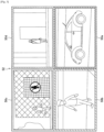
- FIG. 2 is an explanatory diagram that shows an example of a reduced image (reduced image 32).
- the reduced image 32 includes all the regions included in a frame image.
- regions 40 shown in FIG. 2 are regions corresponding to cropped regions, which will be described below.
- the regions corresponding to cropped regions will be described as regions 40 in the reduced image 32.
- FIG. 3 is an explanatory diagram that shows an example of a plurality of cropped images (a set 52 of cropped images 50) generated from one frame image. While the cropped images 50 have a resolution the same as that of the frame image, each of the cropped images 50 only include a part of the region within the frame image, such as shown in FIG. 3 . Accordingly, the camera 10 according to the present embodiment basically generates one reduced image, and one or more cropped images, from one frame image. According to this generation example, a user can confirm a full view photographed by the camera 10, and a user can confirm a region of an attention target with a high resolution. Also, the total data amount can be suppressed compared to that of the frame image.
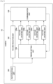
- the camera 10 includes a photographing unit 100, a picture reduction unit 102, a region setting unit 104, a plurality of picture cropping units 106, and a communication unit 108.
- a photographing unit 100 includes a photographing unit 100, a picture reduction unit 102, a region setting unit 104, a plurality of picture cropping units 106, and a communication unit 108.
- a communication unit 108 includes a communication unit 108.
- FIG. 4 where four picture cropping units 106 are included, it is not limited to such an example, and may include an arbitrary number of one or more.
- the photographing unit 100 has a function that acquires a frame image, by forming an external picture on an imaging element such as a Charge Coupled Device (CCD) or a Complementary Metal Oxide Semiconductor (CMOS), for example, through a lens.
- an imaging element such as a Charge Coupled Device (CCD) or a Complementary Metal Oxide Semiconductor (CMOS), for example, through a lens.
- CCD Charge Coupled Device
- CMOS Complementary Metal Oxide Semiconductor
- the picture reduction unit 102 generates a reduced image by reducing the frame image acquired by the photographing unit 100 to a prescribed size.
- the region setting unit 104 sets cropped regions, which are regions that become a generation source of cropped images, in the frame image acquired by the photographing unit 100. For example, the region setting unit 104 sets cropped regions only of the number of picture cropping units 106 included in the camera 10, from the frame image acquired by the photographing unit 100.
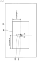
- FIG. 5 is an explanatory diagram that shows a setting example of a cropped region by the region setting unit 104. Note that, in FIG. 5 , the length of a horizontal width of the cropped region 40 is described as "crop_width”, and the length of a vertical width of the cropped region 40 is described as “crop_height”.
- the region setting unit 104 detects an object of a detection target such as a person 300 from within the frame image 30, and sets the cropped region 40 based on a detection position 302 of the object.
- the picture cropping unit 106 is an example of a segmented image generation unit in an embodiment of the present disclosure.
- the picture cropping unit 106 generates a cropped image by segmenting the cropped region set by the region setting unit 104 from the frame image acquired by the photographing unit 100.
- the picture cropping unit 106a generates a cropped image 50a from a cropped region corresponding to the region 40a shown in FIG. 2 , set by the region setting unit 104.
- the picture cropping unit 106b generates a cropped image 50b from a cropped region corresponding to the region 40b shown in FIG. 2 , set by the region setting unit 104.
- the communication unit 108 is an example of an acquisition unit according to the present embodiment.
- the communication unit 108 performs transmission and reception of various types of information between apparatuses connected to the communication network 24, via the communication network 24, which will be described below.
- the communication unit 108 transmits, to the storage 20, the reduced image acquired by the picture reduction unit 102, and the plurality of cropped images generated by the plurality of picture cropping units 106.
- the communication unit 108 receives, from the monitoring terminal 22, detection specification information for selecting a cropping target, set by a user.
- detection specification information may be stored from the beginning by the camera 10, instead of being received from the monitoring terminal 22.
- detection specification information may be stored from the beginning by the camera 10, instead of being received from the monitoring terminal 22.
- a description will be made by centering on an example where detection specification information is received from the monitoring terminal 22.
- the storage 20 is a storage apparatus for storing the reduced image and cropped images received from the camera 10.
- the storage 20 associates and stores identification information of the camera 10, and at the time of photographing, the received reduced image, and the received plurality of cropped images.
- the storage 20 can be set, for example, to a data center, a monitoring center where monitoring staff are employed or the like.
- the monitoring terminal 22 is an information processing terminal for displaying the reduced image and cropped images generated by the camera 10.
- This monitoring terminal 22 can be set, for example, in a monitoring center, and can be used by monitoring staff.
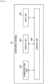
- FIG. 6 is a function block diagram that shows a configuration of the monitoring terminal 22 according to the present embodiment.
- the monitoring terminal 22 has a control unit 220, a communication unit 222, a display unit 224, and an input unit 226.
- the control unit 220 generally controls the operations of the monitoring terminal 22, by using hardware such as a Central Processing Unit (CPU), a Random Access Memory (RAM), and a Read Only Memory (ROM) built into the monitoring terminal 22.
- CPU Central Processing Unit
- RAM Random Access Memory
- ROM Read Only Memory
- the communication unit 222 performs transmission and reception of various types of information between apparatuses connected to the communication network 24, via the communication network 24, which will be described below.
- the communication unit 222 receives, from the storage 20, the reduced image and cropped images stored in the storage 20.
- the communication unit 222 it is possible for the communication unit 222 to directly receive, from the camera 10, the reduced image and plurality of cropped images generated by the camera 10.
- the communication unit 222 transmits, to the camera 10, detection specification information for selecting an object of a cropping target, input by a user on an evaluation standard setting screen, which will be described below, in accordance with a control of the control unit 220.
- the display unit 224 is constituted, for example, by a display such as a Liquid Crystal Display (LCD), or an Organic Light Emitting Diode (OLED).
- This display unit 224 displays, for example, a monitoring screen that includes the reduced image or cropped images received from the storage 20.
- the display unit 224 displays an evaluation standard setting screen, in accordance with a control of the control unit 220.
- This evaluation standard setting screen is a screen for a user to set (or change) detection specification information used for determining an object of a cropping target from within a frame image photographed by the camera 10.
- detection specification information is set so as to include one or more evaluation items selected on the evaluation standard setting screen, and evaluation standards of these evaluation items.
- the evaluation standard setting screen 60 includes, for example, setting columns 600 of a plurality of evaluation items such as an object size setting column 600a, and an object speed setting column 600b.
- the plurality of evaluation items includes, for example, an object size, an object speed, an object staying time, an object aspect ratio, a predicted time up until an object goes outside the screen, a distance between an object and a home position, an object tracking time, an object stopping time or the like.
- an object aspect ratio is an evaluation item used for distinguishing an object type of a detection target, such as distinguishing between a person and a vehicle, for example. Note that, being able to identify an object type with a low calculation amount can be included as an advantage of using an aspect ratio.
- a predicted time up until an object goes outside the screen is a time at which an object movement speed is calculated based on a change of position in a past frame, for example, and is predicted based on the calculated movement speed.
- This "predicted time up until an object goes outside the screen" is an evaluation item used in the case where photographing at least one time, for example, even if it is an object moving at a high speed.
- a home position is an example of a monitoring target region in an embodiment of the present disclosure. This home position is determined, for example, for each detection frame of an object.
- a detection frame can be determined, for example, for each location where a user desires to monitor such as a passage, a building entrance, or a restricted region.
- a detection frame of an object may be set in association with each of the plurality of picture cropping units 106 included in the camera 10.
- FIG. 7 shows an object speed, an object aspect ratio, a distance up to a home position, and an object stopping time selected as evaluation items by a user.
- FIG. 7 shows evaluation standards specified so that an evaluation becomes higher, such as an object with an object speed faster than a stipulated value, an object with an object aspect ratio smaller than a stipulated value, an object with a distance up to a home position longer than a stipulated value, or an object with an object stopping time shorter than a stipulated value.
- the input unit 226 includes, for example, an input apparatus such as a mouse, a keyboard, a touch panel, or a microphone. This input unit 226 receives various types of inputs by a user to the monitoring terminal 22. For example, the input unit 226 receives an input of detection specification information to the evaluation standard setting screen displayed in the display unit 224.
- the communication network 24 is a wired or wireless transmission path of information transmitted from apparatuses connected to the communication network 24.
- the communication network 24 may include a public line network such as a telephone line network, the Internet, or a satellite communication network, or various types of Local Area Networks (LAN), Wide Area Networks (WAN) or the like that include an Ethernet (registered trademark).
- the communication network 24 may include a dedicated line network such as an Internet Protocol-Virtual Private Network (IP-VPN).
- IP-VPN Internet Protocol-Virtual Private Network
- the image processing system according to the present embodiment is not limited to the above described configuration.
- the storage 20 and the monitoring terminal 22 may be integrally constituted.
- the camera 10 it is possible for the camera 10 according to the present embodiment to automatically select the most suitable cropping target, based on detection specification information specified by a user.
- the features of the configuration of the camera 10 according to the present embodiment are related, in particular, to the configuration of the region setting unit 104.
- a configuration of the region setting unit 104 will be additionally described in detail by referring to FIG. 8 .
- the region setting unit 104 includes an object detection unit 120, a cropped region determination unit 122, and an overlapping decision unit 124.
- the object detection unit 120 detects an object of a cropping target from within a detection frame in a frame image (hereinafter, called a present frame image) acquired by the photographing unit 100, for example, based on detection specification information received from the monitoring terminal 22. For example, the object detection unit 120 detects, as a cropping target, an object with the highest value evaluated by an evaluation standard of an evaluation item included in the received detection specification information, from among a plurality of objects included in a detection frame.
- the object detection unit 120 detects an object of a cropping target based on a combination of evaluation values by the evaluation standards of each of the plurality of evaluation items included in this detection specification information, from among a plurality of objects included in a detection frame. For example, in the above described case, the object detection unit 120 first performs an evaluation for each of a plurality of objects included in a detection frame, in accordance with the evaluation standards for each of the plurality of evaluation items shown by this detection specification information, and calculates a total of the evaluation values of each evaluation item. Then, the object detection unit 120 detects, as a cropping target, an object with the highest total of the evaluation values of each evaluation item.
- the object detection unit 120 decides whether or not to switch an object of a detection target, based on a comparison between the length of time that the present object of a detection target is estimated to have stopped, and a stopping upper limit time included in this detection specification information.
- the object detection unit 120 decides to switch an object of a detection target to another object. Further, in the case where the length of time that the present object of a detection target is estimated to have stopped is smaller than a stopping upper limit time, the object detection unit 120 decides to set an object of a detection target the same as in the previous frame image. Note that, in the case where a change amount of a detection position of an object of a detection target between consecutive frame images is within a prescribed range, for example, it is possible for the object detection unit 120 to estimate that this object is stopped.
- the object detection unit 120 decides whether or not to switch an object of a detection target, based on a comparison between a continuation time of the detection of the present object of a detection target, and a tracking upper limit time included in this detection specification information.
- a tracking upper limit time is an upper limit value of time to maintain an object of a cropping target to a same object.
- the object detection unit 120 decides to switch an object of a detection target to another object. Further, in the case where a continuation time of the detection of the present object of a detection target is a tracking upper limit time or less, the object detection unit 120 decides to set an object of a detection target the same as in the previous frame image.
- the object detection unit 120 decides whether or not to switch an object of a detection target, based on a comparison between a distance between a home position set beforehand in a moving image and the present object of a detection target, and a monitoring upper limit distance included in this detection specification information.
- the object detection unit 120 decides to switch an object of a detection target to another object, such as an object positioned closest to the home position, for example. Further, in the case where a distance between the home position and the present object of a detection target is within a monitoring upper limit distance, the object detection unit 120 decides to set an object of a detection target the same as in the previous frame image.
- the object detection unit 120 decides to switch an object of a cropping target of any of the decided cropped regions to another object.
- the object detection unit 120 decides to switch an object of a cropping target of any of the overlapping cropped regions to another object.
- the object detection unit 120 may decide a cropped region for which an object of a cropping target is to be switched to another object (hereinafter, called a cropping target switching region), from among the cropped regions for which it has been decided that the cropped regions are overlapping by the overlapping decision unit 124, in accordance with the received detection specification information. For example, the object detection unit 120 may determine a cropped region, which includes a cropping target with a low value of an evaluation item included in the received detection specification information, from among the overlapping cropped regions, to be a cropping target switching region. Further, the object detection unit 120 may determine a cropped region, for which the detection (tracking) of an object of a cropping target is continuing from an earlier time, from among the overlapping cropped regions, to be a cropping target switching region.
- a cropping target switching region another object
- the object detection unit 120 it is possible for the object detection unit 120 to detect a prescribed number of objects, such as a number within the number of picture cropping units 106, for example, from within the present frame image.
- the object detection unit 120 may not detect any objects.
- the cropped region determination unit 122 is an example of a segmented region determination unit in an embodiment of the present disclosure.
- the cropped region determination unit 122 determines a cropped region in the present frame image, so that a detection position of an object detected by the object detection unit 120 is included.
- the cropped region determination unit 122 determines a cropped region in the present frame image, so that a detection position of an object detected by the object detection unit 120 becomes the center of the cropped region.
- the shape and size of the cropped region in the frame image is basically determined the same in all of the frame images. Further, the size of the cropped region is basically determined to a predetermined size.
- the cropped region determination unit 122 may determine not to output any region. Or, in the above described case, the cropped region determination unit 122 may determine a region that includes a home position as a cropped region.
- the overlapping decision unit 124 decides whether or not this cropped region is overlapping with another cropped region, based on an overlapping decision condition included in the received detection specification information. For example, in the case where the ratio of the area of an overlapping region is a prescribed threshold or more, with respect to the area of the cropped region, the overlapping decision unit 124 decides that this cropped region is overlapping with the other cropped region. Further, in the case where a distance from the center of this cropped region up to another cropped region is a prescribed threshold or less, the overlapping decision unit 124 decides that this cropped region is overlapping with the other cropped region.
- FIG. 9 to FIG. 11 an operation example will be described in a scene where the camera 10 has four picture cropping units 106, and one reduced image and four cropped images are generated from one frame image. Note that, this operation is repeatedly executed for each prescribed frame rate.
- FIG. 9 is a flow chart that shows an operation example according to the present embodiment. As shown in FIG. 9 , first the photographing unit 100 of the camera 10 acquires a frame image by photographing an external picture, when a prescribed photographing timing is reached (S101).
- the picture reduction unit 102 generates a reduced image by reducing the frame image acquired in step S101 (hereinafter, called a present frame image) to a prescribed size (S103).
- the camera 10 repeatedly performs a "cropped image generation process", which will be described below, the number of the picture cropping units 106, that is, four times (S105 to S111).
- the communication unit 108 transmits the reduced image generated in S103 and the four cropped images generated in step S107 to the storage 20 (S113).
- the object detection unit 120 of the camera 10 detects an object set as an I-th placed cropping target, that is, an object being tracked (S151).
- the cropped region determination unit 122 determines a cropped region in the present frame image, so that a detection position of the object detected in S151 becomes the center of the cropped region (S153).
- the object detection unit 120 decides whether or not the total of a tracking time (from a tracking start) of the object detected in S151 has passed a tracking upper limit time (S161). In the case where the total of the object tracking time has passed a tracking upper limit time (S161: Yes), the object detection unit 120 switches the I-th placed cropping target to another object (S163). Afterwards, the camera 10 again performs the operation of S153.
- next the object detection unit 120 decides whether or not the total of a stopping time (from the time when a stop has been detected) of the object detected in S151 has passed a stopping upper limit time (S165). In the case where the total of the object stopping time has passed a stopping upper limit time (S165: Yes), the object detection unit 120 performs the operation of S163.
- the overlapping decision unit 124 decides whether or not the cropped region determined in S153 is overlapping with another cropped region within the same frame image (S167). In the case where this cropped region is overlapping with another cropped region (S167: Yes), the object detection unit 120 performs the operation of S163.
- the picture cropping unit 106 generates a cropped image, by segmenting this cropped region from the present frame image (S169).
- the camera 10 detects an object based on an evaluation item selected by a user from among a plurality of evaluation items, and determines a cropped region in the present frame image, so that a detection position of the detected object is included. Accordingly, the most suitable cropping target can be automatically selected, from among a plurality of objects included in the frame image. Further, an object of a cropping target can be similarly optimized with respect to the length of time to be cropped.
- the camera 10 switches an object of a cropping target to another object, and determines a cropped region so that the object after switching becomes the center. Accordingly, even if an object determined once to be a cropping target continues to be positioned at the same location, an object of a cropping target is changed to another object, if a stopping condition time has passed. Therefore, the same location continuing to be set to a segmented region for a long time can be prevented.
- the camera 10 can perform the generation of a cropped image in real time.
- the present embodiment it is possible to generate a reduced image and cropped images only with the camera 10 unit. Accordingly, since it may not be necessary for the camera 10 to transmit a frame image to another apparatus such as a server, for example, for generating a reduced image and cropped images, the communication amount can be reduced.
- the image processing apparatus according to an embodiment of the present disclosure is the camera 10, it is not limited to such an example.
- the image processing apparatus according to the present embodiment may be the monitoring terminal 22.
- the image processing apparatus may be the server.
- this server and the storage 20 may be integrally constituted.
- a tracking upper limit time of an object, and a stopping upper limit time of an object are values included in detection specification information, that is, are fixed values, it is not limited to such an example, and the camera 10 may dynamically determine a tracking upper limit time, or a stopping upper limit time.
- the camera 10 may dynamically determine a tracking upper limit time, or a stopping upper limit time, for each detection frame.
- the camera 10 may make a tracking upper limit time longer as the number of untracked objects decreases, for each detection frame.
- a monitoring target region is included, for example, in a detection frame, the camera 10 may make a tracking upper limit time longer.
- a computer program for causing hardware such as a CPU, a ROM, and a RAM, for example, to exhibit functions the same as the above described picture reduction unit 102, region setting unit 104, and picture cropping unit 106 can be provided. Further, a recording medium to which this computer program is recorded can also be provided.
Description
- This application claims the benefit of Japanese Priority Patent Application
JP 2015-082275 filed April 14, 2015 - The present disclosure relates to an image processing apparatus, an image processing method, and an image processing system.
- In related art, technology for segmenting a region of an object such as a person of a detection target, within a photographed image, has been variously developed.
- For example,
PTL 1 discloses technology that detects moving bodies within an image photographed by a fish-eye lens camera, and respectively segments circumscribed quadrangle regions of each of the detected moving bodies. Further,PTL 2 discloses technology that extracts, based on position information of a partial region extracted with an immediately preceding frame image, and a physical feature amount analyzed from a present frame image, a partial region from each frame image. Further, PTL 3 discloses technology that detects a moving body with a size, an existing time, or a moving speed the largest from among moving bodies extracted from picture data, and segments a region that includes the detected moving body. -
- [PTL 1]
JP 2001-333422A - [PTL 2]
JP 2004-334587A - [PTL 3]
JP 2014-222825A - Prior Art Includes:
US 8879/789 B1 ,US 2005/117778 A1 and also: - D1
US 2009/244390 A1 (FERIS ROGERIO SCHMIDT [US] ET AL) 1 October 2009 (2009-10-01) - D2 Nils T. Siebel ET AL: "Fusion of Multiple Tracking Algorithms for Robust People Tracking" In: "Correct System Design", 1 January 2002 (2002-01-01), Springer International Publishing, Cham 032548, XP055287552, ISSN: 0302-9743 ISBN: 978-3-642-33352-1 vol. 2353, pages 373-387, DOI: 10.1007/3-540-47979-1_25,
- D3
US 8 879 789 B1 (FIGOV ZVI [IL] ET AL) 4 November 2014 (2014-11-04) and - D4
US 2005/117778 A1 (CRABTREE RALPH N [US]) 2 June 2005 (2005-06-02) Document D1 discloses identifying the object as a target object based on the determined length of time the movement of the object is below a predetermined movement threshold. - However, in the technology disclosed in
PTL 1 to PTL3, there will be cases where the position of a segmented region is restricted. For example, in the technology disclosed in PTL 3, when an object determined once to be a detection target continues to be positioned at the same location, the same location will continue to be set for a long time as a segmented region. - Accordingly, the present
invention proposes a new and improved image processing apparatus, image processing method, and image processing system, capable of adaptively determining a segmented region for the length of time that an object of a detection target is stopped. - According to an embodiment of the present invention there is provided an image processing apparatus according to
claim 1. - According to an embodiment of the present invention, there is provided a method of an information processing apparatus for identifying a target object according to claim 13
- According to an embodiment of the present invention there is provided a non-transitory computer-readable medium storing instructions which when executed by a computer cause the computer to perform a method of an information processing apparatus for identifying a target object according to claim 14.
- According to an embodiment of the present disclosure such as described above, a segmented region can be adaptively determined for the length of time that an object of a detection target is stopped. Note that, the effect described here is not necessarily limited, and may be any of the effects described within the present disclosure.
-
- [
FIG. 1 ]
FIG. 1 is an explanatory diagram that shows a configuration example of an image processing system according to an embodiment of the present disclosure. - [
FIG. 2 ]
FIG. 2 is an explanatory diagram that shows an example of a reducedimage 32 generated by acamera 10. - [
fig.3]FIG. 3 is an explanatory diagram that shows an example of a plurality of cropped images 50 generated from aframe image 30. - [
fig.4]FIG. 4 is a function block diagram that shows a configuration of thecamera 10 according to a same embodiment. - [
fig.5]FIG. 5 is an explanatory diagram that shows a relationship between theframe image 30 and a croppedregion 40. - [
fig.6]FIG. 6 is a function block diagram that shows a configuration of amonitoring terminal 22 according to a same embodiment. - [
fig.7]FIG. 7 is an explanatory diagram that shows a display example of an evaluation standard setting screen according to a same embodiment. - [
fig.8]FIG. 8 is a function block diagram that shows a configuration of aregion setting unit 104 according to a same embodiment. - [
fig.9]FIG. 9 is a flow chart that shows the operations according to a same embodiment. - [
fig.10]FIG. 10 is a flow chart that shows a part of the operations of a cropped image generation process according to a same embodiment. - [
fig.11]FIG. 11 is a flow chart that shows a part of the operations of a cropped image generation process according to a same embodiment. - Hereinafter, (a) preferred embodiment(s) of the present disclosure will be described in detail with reference to the appended drawings. In this specification and the appended drawings, structural elements that have substantially the same function and structure are denoted with the same reference numerals, and repeated explanation of these structural elements is omitted.
- Further, in the present description and drawings, there will be cases where a plurality of structural elements having substantially the same function configuration are distinguished from each other by attaching different letters of the alphabet after the same reference sign. For example, a plurality of configurations having substantially the same function configuration will be distinguished such as a
picture cropping unit 106a and apicture cropping unit 106b as necessary. However, in the case where it may not be necessary to distinguish structural elements having substantially the same function configuration, only the same reference sign will be attached. For example, in the case where it may not be necessary to distinguish thepicture cropping unit 106a and thepicture cropping unit 106b, they will be simply called a picture cropping unit 106. - Further, the "Description of Embodiments" will be described according to the order of items shown below.
- 1. Basic configuration of the image processing system
- 2. Detailed description of the embodiments
- 3. Modifications
- The present disclosure can be implemented by various modes, such as described in detail in "2. Detailed description of the embodiments" as an example. Firstly, the basic configuration of an image processing system according to the present embodiment will be described by referring to
FIG. 1 . - As shown in
FIG. 1 , an image processing system according to the present embodiment includes acamera 10, astorage 20, amonitoring terminal 22, and acommunication network 24. - The
camera 10 is an example of an image processing apparatus in an embodiment of the present disclosure. Thecamera 10 is an apparatus for photographing a moving image of an external environment. Thiscamera 10 can be set at a location where there are many people or a large amount of vehicle traffic, a location of a monitoring target or the like. For example, thecamera 10 may be set at a road, a train station, an airport, a commercial building, an amusement park, a park, a parking lot, a restricted area or the like. - Further, it is possible for the
camera 10 to generate another image by using a photographed frame image, and to transmit the generated other image to another apparatus via thecommunication network 24, which will be described below. Here, the frame image is, for example, an image having a resolution with an upper limit that thecamera 10 is capable of photographing. As an example, the frame image may be a 4K image. - For example, the
camera 10 generates another image with a small amount of data based on the frame image. The reason for this is that since the frame image has a large amount of data, it is not desirable to transmit the frame image itself to another apparatus, for example, due to a reason such as taking time to transfer. - Here, an example of another image generated by the
camera 10 is a reduced image, which is an image where the resolution of the frame image is simply lowered, or a cropped image, which is an image where a region of an attention target is cropped (cut out). Note that, the reduced image may be, for example, an HD image. -
FIG. 2 is an explanatory diagram that shows an example of a reduced image (reduced image 32). The reducedimage 32 includes all the regions included in a frame image. On the other hand, since a region of an attention target, such as a person's face, for example, can become extremely small in the reducedimage 32, such as shown inFIG. 2 , it can become difficult to visually recognize. Note that,regions 40 shown inFIG. 2 are regions corresponding to cropped regions, which will be described below. Ordinarily, while cropped regions are set within a frame image, inFIG. 2 , for the sake of convenience of the description, the regions corresponding to cropped regions will be described asregions 40 in the reducedimage 32. - Further,
FIG. 3 is an explanatory diagram that shows an example of a plurality of cropped images (aset 52 of cropped images 50) generated from one frame image. While the cropped images 50 have a resolution the same as that of the frame image, each of the cropped images 50 only include a part of the region within the frame image, such as shown inFIG. 3 . Accordingly, thecamera 10 according to the present embodiment basically generates one reduced image, and one or more cropped images, from one frame image. According to this generation example, a user can confirm a full view photographed by thecamera 10, and a user can confirm a region of an attention target with a high resolution. Also, the total data amount can be suppressed compared to that of the frame image. - Here, an internal configuration of the
camera 10 will be described by referring toFIG. 4 . As shown inFIG. 4 , thecamera 10 includes a photographingunit 100, apicture reduction unit 102, aregion setting unit 104, a plurality of picture cropping units 106, and acommunication unit 108. Note that, while an example is shown inFIG. 4 where four picture cropping units 106 are included, it is not limited to such an example, and may include an arbitrary number of one or more. - The photographing
unit 100 has a function that acquires a frame image, by forming an external picture on an imaging element such as a Charge Coupled Device (CCD) or a Complementary Metal Oxide Semiconductor (CMOS), for example, through a lens. For example, the photographingunit 100 acquires a frame image, by photographing an external picture for each prescribed frame rate. - The
picture reduction unit 102 generates a reduced image by reducing the frame image acquired by the photographingunit 100 to a prescribed size. - The
region setting unit 104 sets cropped regions, which are regions that become a generation source of cropped images, in the frame image acquired by the photographingunit 100. For example, theregion setting unit 104 sets cropped regions only of the number of picture cropping units 106 included in thecamera 10, from the frame image acquired by the photographingunit 100. -
FIG. 5 is an explanatory diagram that shows a setting example of a cropped region by theregion setting unit 104. Note that, inFIG. 5 , the length of a horizontal width of the croppedregion 40 is described as "crop_width", and the length of a vertical width of the croppedregion 40 is described as "crop_height". - As shown in
FIG. 5 , theregion setting unit 104 detects an object of a detection target such as aperson 300 from within theframe image 30, and sets the croppedregion 40 based on adetection position 302 of the object. - The picture cropping unit 106 is an example of a segmented image generation unit in an embodiment of the present disclosure. The picture cropping unit 106 generates a cropped image by segmenting the cropped region set by the
region setting unit 104 from the frame image acquired by the photographingunit 100. - For example, in the example shown in
FIG. 3 , four cropped images 50 generated by each of the four picture cropping units 106 are shown. As shown inFIG. 3 , for example, thepicture cropping unit 106a generates a croppedimage 50a from a cropped region corresponding to theregion 40a shown inFIG. 2 , set by theregion setting unit 104. Further, thepicture cropping unit 106b generates a croppedimage 50b from a cropped region corresponding to theregion 40b shown inFIG. 2 , set by theregion setting unit 104. - The
communication unit 108 is an example of an acquisition unit according to the present embodiment. Thecommunication unit 108 performs transmission and reception of various types of information between apparatuses connected to thecommunication network 24, via thecommunication network 24, which will be described below. For example, thecommunication unit 108 transmits, to thestorage 20, the reduced image acquired by thepicture reduction unit 102, and the plurality of cropped images generated by the plurality of picture cropping units 106. Further, thecommunication unit 108 receives, from the monitoringterminal 22, detection specification information for selecting a cropping target, set by a user. - Note that, detection specification information may be stored from the beginning by the
camera 10, instead of being received from the monitoringterminal 22. Hereinafter, a description will be made by centering on an example where detection specification information is received from the monitoringterminal 22. - The
storage 20 is a storage apparatus for storing the reduced image and cropped images received from thecamera 10. For example, thestorage 20 associates and stores identification information of thecamera 10, and at the time of photographing, the received reduced image, and the received plurality of cropped images. Note that, thestorage 20 can be set, for example, to a data center, a monitoring center where monitoring staff are employed or the like. - The
monitoring terminal 22 is an information processing terminal for displaying the reduced image and cropped images generated by thecamera 10. This monitoring terminal 22 can be set, for example, in a monitoring center, and can be used by monitoring staff. - Here, a configuration of the
monitoring terminal 22 will be described in detail.FIG. 6 is a function block diagram that shows a configuration of themonitoring terminal 22 according to the present embodiment. As shown inFIG. 6 , the monitoringterminal 22 has acontrol unit 220, acommunication unit 222, adisplay unit 224, and aninput unit 226. - The
control unit 220 generally controls the operations of themonitoring terminal 22, by using hardware such as a Central Processing Unit (CPU), a Random Access Memory (RAM), and a Read Only Memory (ROM) built into themonitoring terminal 22. - The
communication unit 222 performs transmission and reception of various types of information between apparatuses connected to thecommunication network 24, via thecommunication network 24, which will be described below. For example, thecommunication unit 222 receives, from thestorage 20, the reduced image and cropped images stored in thestorage 20. Note that, it is possible for thecommunication unit 222 to directly receive, from thecamera 10, the reduced image and plurality of cropped images generated by thecamera 10. - Further, the
communication unit 222 transmits, to thecamera 10, detection specification information for selecting an object of a cropping target, input by a user on an evaluation standard setting screen, which will be described below, in accordance with a control of thecontrol unit 220. - The
display unit 224 is constituted, for example, by a display such as a Liquid Crystal Display (LCD), or an Organic Light Emitting Diode (OLED). Thisdisplay unit 224 displays, for example, a monitoring screen that includes the reduced image or cropped images received from thestorage 20. - Further, the
display unit 224 displays an evaluation standard setting screen, in accordance with a control of thecontrol unit 220. This evaluation standard setting screen is a screen for a user to set (or change) detection specification information used for determining an object of a cropping target from within a frame image photographed by thecamera 10. For example, detection specification information is set so as to include one or more evaluation items selected on the evaluation standard setting screen, and evaluation standards of these evaluation items. - Here, a display example of the evaluation standard setting screen (an evaluation standard setting screen 60) will be described by referring to
FIG. 7 . As shown inFIG. 7 , the evaluationstandard setting screen 60 includes, for example, setting columns 600 of a plurality of evaluation items such as an objectsize setting column 600a, and an objectspeed setting column 600b. As shown inFIG. 7 , the plurality of evaluation items includes, for example, an object size, an object speed, an object staying time, an object aspect ratio, a predicted time up until an object goes outside the screen, a distance between an object and a home position, an object tracking time, an object stopping time or the like. Here, an object aspect ratio is an evaluation item used for distinguishing an object type of a detection target, such as distinguishing between a person and a vehicle, for example. Note that, being able to identify an object type with a low calculation amount can be included as an advantage of using an aspect ratio. - Further, a predicted time up until an object goes outside the screen is a time at which an object movement speed is calculated based on a change of position in a past frame, for example, and is predicted based on the calculated movement speed. This "predicted time up until an object goes outside the screen" is an evaluation item used in the case where photographing at least one time, for example, even if it is an object moving at a high speed. Note that, a home position is an example of a monitoring target region in an embodiment of the present disclosure. This home position is determined, for example, for each detection frame of an object. As an example, a detection frame can be determined, for example, for each location where a user desires to monitor such as a passage, a building entrance, or a restricted region. Further, a detection frame of an object may be set in association with each of the plurality of picture cropping units 106 included in the
camera 10. - For example, the example shown in
FIG. 7 shows an object speed, an object aspect ratio, a distance up to a home position, and an object stopping time selected as evaluation items by a user. In addition,FIG. 7 shows evaluation standards specified so that an evaluation becomes higher, such as an object with an object speed faster than a stipulated value, an object with an object aspect ratio smaller than a stipulated value, an object with a distance up to a home position longer than a stipulated value, or an object with an object stopping time shorter than a stipulated value. - The
input unit 226 includes, for example, an input apparatus such as a mouse, a keyboard, a touch panel, or a microphone. Thisinput unit 226 receives various types of inputs by a user to themonitoring terminal 22. For example, theinput unit 226 receives an input of detection specification information to the evaluation standard setting screen displayed in thedisplay unit 224. - The
communication network 24 is a wired or wireless transmission path of information transmitted from apparatuses connected to thecommunication network 24. For example, thecommunication network 24 may include a public line network such as a telephone line network, the Internet, or a satellite communication network, or various types of Local Area Networks (LAN), Wide Area Networks (WAN) or the like that include an Ethernet (registered trademark). Further, thecommunication network 24 may include a dedicated line network such as an Internet Protocol-Virtual Private Network (IP-VPN). - Note that, the image processing system according to the present embodiment is not limited to the above described configuration. For example, the
storage 20 and themonitoring terminal 22 may be integrally constituted. Or, it is possible for the present image processing system to not include thestorage 20 or themonitoring terminal 22. - In the above described image processing system, it is possible for the
camera 10 according to the present embodiment to automatically select the most suitable cropping target, based on detection specification information specified by a user. - Heretofore, a configuration of the image processing system according to the present embodiment has been described. Next, a configuration of the
camera 10 according to the present embodiment will be described in detail. - The features of the configuration of the
camera 10 according to the present embodiment are related, in particular, to the configuration of theregion setting unit 104. Hereinafter, a configuration of theregion setting unit 104 will be additionally described in detail by referring toFIG. 8 . - As shown in
FIG. 8 , theregion setting unit 104 includes anobject detection unit 120, a croppedregion determination unit 122, and an overlappingdecision unit 124. - The
object detection unit 120 detects an object of a cropping target from within a detection frame in a frame image (hereinafter, called a present frame image) acquired by the photographingunit 100, for example, based on detection specification information received from the monitoringterminal 22. For example, theobject detection unit 120 detects, as a cropping target, an object with the highest value evaluated by an evaluation standard of an evaluation item included in the received detection specification information, from among a plurality of objects included in a detection frame. - Note that, in the case where the received detection specification information includes a plurality of evaluation items, it is also possible for the
object detection unit 120 to detect an object of a cropping target based on a combination of evaluation values by the evaluation standards of each of the plurality of evaluation items included in this detection specification information, from among a plurality of objects included in a detection frame. For example, in the above described case, theobject detection unit 120 first performs an evaluation for each of a plurality of objects included in a detection frame, in accordance with the evaluation standards for each of the plurality of evaluation items shown by this detection specification information, and calculates a total of the evaluation values of each evaluation item. Then, theobject detection unit 120 detects, as a cropping target, an object with the highest total of the evaluation values of each evaluation item. - Further, in the case where the received detection specification information includes the evaluation item "object stopping time", the
object detection unit 120 decides whether or not to switch an object of a detection target, based on a comparison between the length of time that the present object of a detection target is estimated to have stopped, and a stopping upper limit time included in this detection specification information. - In the case where the length of time that the present object of a detection target is estimated to have stopped is larger than a stopping upper limit time, the
object detection unit 120 decides to switch an object of a detection target to another object. Further, in the case where the length of time that the present object of a detection target is estimated to have stopped is smaller than a stopping upper limit time, theobject detection unit 120 decides to set an object of a detection target the same as in the previous frame image. Note that, in the case where a change amount of a detection position of an object of a detection target between consecutive frame images is within a prescribed range, for example, it is possible for theobject detection unit 120 to estimate that this object is stopped. - Further, in the case where the received detection specification information includes the evaluation item "object tracking time", the
object detection unit 120 decides whether or not to switch an object of a detection target, based on a comparison between a continuation time of the detection of the present object of a detection target, and a tracking upper limit time included in this detection specification information. Note that, a tracking upper limit time is an upper limit value of time to maintain an object of a cropping target to a same object. - In the case where a continuation time of the detection of the present object of a detection target exceeds a tracking upper limit time, the
object detection unit 120 decides to switch an object of a detection target to another object. Further, in the case where a continuation time of the detection of the present object of a detection target is a tracking upper limit time or less, theobject detection unit 120 decides to set an object of a detection target the same as in the previous frame image. - Further, in the case where the received detection specification information includes the evaluation item "distance between an object and a home position", the
object detection unit 120 decides whether or not to switch an object of a detection target, based on a comparison between a distance between a home position set beforehand in a moving image and the present object of a detection target, and a monitoring upper limit distance included in this detection specification information. - For example, in the case where a distance between the home position and the present object of a detection target exceeds a monitoring upper limit distance, the
object detection unit 120 decides to switch an object of a detection target to another object, such as an object positioned closest to the home position, for example. Further, in the case where a distance between the home position and the present object of a detection target is within a monitoring upper limit distance, theobject detection unit 120 decides to set an object of a detection target the same as in the previous frame image. - Further, in the case where it is decided that the cropped regions are overlapping by the overlapping
decision unit 124, which will be described below, theobject detection unit 120 decides to switch an object of a cropping target of any of the decided cropped regions to another object. - For example, in the case where the "switching time of a detection target" included in the received detection specification information has passed, at the time when it is decided that the cropped regions are overlapping by the overlapping
decision unit 124, theobject detection unit 120 decides to switch an object of a cropping target of any of the overlapping cropped regions to another object. - Note that, as a modified example, the
object detection unit 120 may decide a cropped region for which an object of a cropping target is to be switched to another object (hereinafter, called a cropping target switching region), from among the cropped regions for which it has been decided that the cropped regions are overlapping by the overlappingdecision unit 124, in accordance with the received detection specification information. For example, theobject detection unit 120 may determine a cropped region, which includes a cropping target with a low value of an evaluation item included in the received detection specification information, from among the overlapping cropped regions, to be a cropping target switching region. Further, theobject detection unit 120 may determine a cropped region, for which the detection (tracking) of an object of a cropping target is continuing from an earlier time, from among the overlapping cropped regions, to be a cropping target switching region. - Note that, it is possible for the
object detection unit 120 to detect a prescribed number of objects, such as a number within the number of picture cropping units 106, for example, from within the present frame image. - Further, in the case where an object of a cropping target (tracking target) is not present within a detection frame, it is possible for the
object detection unit 120 to not detect any objects. - The cropped
region determination unit 122 is an example of a segmented region determination unit in an embodiment of the present disclosure. The croppedregion determination unit 122 determines a cropped region in the present frame image, so that a detection position of an object detected by theobject detection unit 120 is included. For example, the croppedregion determination unit 122 determines a cropped region in the present frame image, so that a detection position of an object detected by theobject detection unit 120 becomes the center of the cropped region. - Note that, the shape and size of the cropped region in the frame image is basically determined the same in all of the frame images. Further, the size of the cropped region is basically determined to a predetermined size.
- Note that, in the case where no objects have been detected by the
object detection unit 120, the croppedregion determination unit 122 may determine not to output any region. Or, in the above described case, the croppedregion determination unit 122 may determine a region that includes a home position as a cropped region. - At the time when a cropped region has been determined by the cropped
region determination unit 122, the overlappingdecision unit 124 decides whether or not this cropped region is overlapping with another cropped region, based on an overlapping decision condition included in the received detection specification information. For example, in the case where the ratio of the area of an overlapping region is a prescribed threshold or more, with respect to the area of the cropped region, the overlappingdecision unit 124 decides that this cropped region is overlapping with the other cropped region. Further, in the case where a distance from the center of this cropped region up to another cropped region is a prescribed threshold or less, the overlappingdecision unit 124 decides that this cropped region is overlapping with the other cropped region. - Heretofore, a configuration according to an embodiment of the present disclosure has been described. To continue, the operation according to the present embodiment will be described by referring to
FIG. 9 to FIG. 11 . Note that, here, an operation example will be described in a scene where thecamera 10 has four picture cropping units 106, and one reduced image and four cropped images are generated from one frame image. Note that, this operation is repeatedly executed for each prescribed frame rate. -
FIG. 9 is a flow chart that shows an operation example according to the present embodiment. As shown inFIG. 9 , first the photographingunit 100 of thecamera 10 acquires a frame image by photographing an external picture, when a prescribed photographing timing is reached (S101). - To continue, the
picture reduction unit 102 generates a reduced image by reducing the frame image acquired in step S101 (hereinafter, called a present frame image) to a prescribed size (S103). - Afterwards, the
camera 10 repeatedly performs a "cropped image generation process", which will be described below, the number of the picture cropping units 106, that is, four times (S105 to S111). - Afterwards, the
communication unit 108 transmits the reduced image generated in S103 and the four cropped images generated in step S107 to the storage 20 (S113). - Here, the operation of the "cropped image generation process" in S107 will be described in detail by referring to
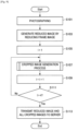
FIG. 10 to FIG. 11 . As shown inFIG. 10 , first theobject detection unit 120 of thecamera 10 detects an object set as an I-th placed cropping target, that is, an object being tracked (S151). - To continue, the cropped
region determination unit 122 determines a cropped region in the present frame image, so that a detection position of the object detected in S151 becomes the center of the cropped region (S153). - Here, the operations after S153 will be described by referring to
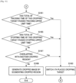
FIG. 11 . As shown inFIG. 11 , after step S153, theobject detection unit 120 decides whether or not the total of a tracking time (from a tracking start) of the object detected in S151 has passed a tracking upper limit time (S161). In the case where the total of the object tracking time has passed a tracking upper limit time (S161: Yes), theobject detection unit 120 switches the I-th placed cropping target to another object (S163). Afterwards, thecamera 10 again performs the operation of S153. - On the other hand, in the case were the total of the object tracking time has not passed a tracking upper limit time (S161: No), next the
object detection unit 120 decides whether or not the total of a stopping time (from the time when a stop has been detected) of the object detected in S151 has passed a stopping upper limit time (S165). In the case where the total of the object stopping time has passed a stopping upper limit time (S165: Yes), theobject detection unit 120 performs the operation of S163. - On the other hand, in the case where the total of the object stopping time has not passed a stopping upper limit time (S165: No), the overlapping
decision unit 124 decides whether or not the cropped region determined in S153 is overlapping with another cropped region within the same frame image (S167). In the case where this cropped region is overlapping with another cropped region (S167: Yes), theobject detection unit 120 performs the operation of S163. - On the other hand, in the case where this cropped region is not overlapping with another cropped region (S167: No), the picture cropping unit 106 generates a cropped image, by segmenting this cropped region from the present frame image (S169).
- Heretofore, for example, as described with reference to
FIG. 4 ,FIG. 8 to FIG. 11 or the like, thecamera 10 according to the present embodiment detects an object based on an evaluation item selected by a user from among a plurality of evaluation items, and determines a cropped region in the present frame image, so that a detection position of the detected object is included. Accordingly, the most suitable cropping target can be automatically selected, from among a plurality of objects included in the frame image. Further, an object of a cropping target can be similarly optimized with respect to the length of time to be cropped. - Further, in the case where the time that an object of a cropping target is estimated to have stopped exceeds a stopping upper limit time, the
camera 10 switches an object of a cropping target to another object, and determines a cropped region so that the object after switching becomes the center. Accordingly, even if an object determined once to be a cropping target continues to be positioned at the same location, an object of a cropping target is changed to another object, if a stopping condition time has passed. Therefore, the same location continuing to be set to a segmented region for a long time can be prevented. - Further, since the determination method of a cropped region by the cropped
region determination unit 122 is a simple method, thecamera 10 can perform the generation of a cropped image in real time. - Further, according to the present embodiment, it is possible to generate a reduced image and cropped images only with the
camera 10 unit. Accordingly, since it may not be necessary for thecamera 10 to transmit a frame image to another apparatus such as a server, for example, for generating a reduced image and cropped images, the communication amount can be reduced. - It should be understood by those skilled in the art that various modifications, combinations, sub-combinations and alterations may occur depending on design requirements and other factors insofar as they are within the scope of the appended claims
- While an example has been described in the above described embodiments where the image processing apparatus according to an embodiment of the present disclosure is the
camera 10, it is not limited to such an example. For example, in the case where (thecontrol unit 220 of) themonitoring terminal 22 has all of the above describedpicture reduction unit 102,region setting unit 104, and plurality of picture cropping units 106, instead of thecamera 10, the image processing apparatus according to the present embodiment may be the monitoringterminal 22. - Further, in the case where a separately included server (illustration omitted) is able to communicate with the
camera 10, for example, via thecommunication network 24, and this server has all of the above describedpicture reduction unit 102,region setting unit 104, and plurality of picture cropping units 106, instead of thecamera 10, the image processing apparatus according to an embodiment of the present disclosure may be the server. Further, this server and thestorage 20 may be integrally constituted. - Further, while an example has been described in the above description where a tracking upper limit time of an object, and a stopping upper limit time of an object, are values included in detection specification information, that is, are fixed values, it is not limited to such an example, and the
camera 10 may dynamically determine a tracking upper limit time, or a stopping upper limit time. For example, thecamera 10 may dynamically determine a tracking upper limit time, or a stopping upper limit time, for each detection frame. As an example, thecamera 10 may make a tracking upper limit time longer as the number of untracked objects decreases, for each detection frame. Further, in the case where a monitoring target region is included, for example, in a detection frame, thecamera 10 may make a tracking upper limit time longer. - Further, according to the above described embodiments, a computer program for causing hardware such as a CPU, a ROM, and a RAM, for example, to exhibit functions the same as the above described
picture reduction unit 102,region setting unit 104, and picture cropping unit 106 can be provided. Further, a recording medium to which this computer program is recorded can also be provided. -
- 10 camera
- 20 storage
- 22 monitoring terminal
- 24 communication network
- 100 photographing unit
- 102 picture reduction unit
- 104 region setting unit
- 106 picture cropping unit
- 108 communication unit
- 120 object detection unit
- 122 cropped region determination unit
- 124 overlapping decision unit
- 220 control unit
- 222 communication unit
- 224 display unit
- 226 input unit
Claims (14)
- An information processing apparatus, comprising:
circuitry (100, 120) configured togenerate or receive a first image and a second image captured before the first image of a sequence of images including an object being identified as the target object in the second image,determine a length of time movement of the object is below a predetermined movement threshold, anddecide whether to switch the target object to be identified as another object in the first image based on the determined length of time that the movement of the object is below the predetermined movement threshold and a length of time the object is identified as the target object. - The information processing apparatus according to claim 1, wherein the circuitry is configured to change the target object from the object to a different object included in the first image when the circuitry determines not to continue identifying the object as the target object.
- The information processing apparatus according to claim 1, wherein the circuitry is configured to:determine whether the length of time the movement of the object is below the predetermined movement threshold exceeds an upper time limit, andidentify the object as the target object when the length of time the movement of the object is below the predetermined movement threshold is less than or equal to the upper time limit.
- The information processing apparatus according to claim 1, wherein the circuitry is configured to:determine whether the length of time the movement of the object is below the predetermined movement threshold exceeds an upper time limit, andidentify a different object included in the first image as the target object when the length of the time the movement of the object is below the predetermined movement threshold exceeds the upper time limit.
- The information processing apparatus according to claim 1, whereinthe target object is a cropping target, andthe circuitry is configured to generate a cropped image by cropping the first image based on a position of the object within the first image when the object is identified as the target object.
- The information processing apparatus according to claim 1, whereinthe circuitry is configured to transmit a plurality of image streams,the plurality of image streams includes cropped images of different portions of each of the sequence of images, andeach of the different portions corresponds to a different object.
- The information processing apparatus according to claim 6, wherein the circuitry is configured to:generate a lower resolution version of the first image, andtransmit the cropped image and the lower resolution version of the first image.
- The information processing apparatus according to claim 1, wherein the circuitry is configured to:set an upper time limit based on a user input, andidentify the object as the target object based on a comparison of the length of time the movement of the object is below the predetermined movement threshold and the set upper time limit.
- The information processing apparatus according to claim 1, wherein the circuitry is configured to:set different upper time limits for different images, including the first image, in the sequence of images, andidentify the object as the target object in the first image based on a comparison of the length of time the movement of the object is below the predetermined movement threshold and the upper time limit set for the first image.
- The information processing apparatus according to claim 1, wherein the circuitry is configured to:detect a plurality of objects included in the first image, andidentify a subset of the plurality of objects as target objects in the first image when a number of the plurality of objects exceeds a predetermined maximum number of target objects, the predetermined maximum number being greater than 1.
- The information processing apparatus according to claim 1, wherein the circuitry is configured to:
continue to identify the object as the target object in subsequent successive images of the sequence of images, including the object and captured after the first image, until the length of time the movement of the object is below the predetermined movement threshold exceeds an upper limit time limit. - The information processing apparatus according to claim 1, wherein the circuitry is configured to:determine a plurality of cropped regions of the first image, each of the cropped images corresponding to a different target object, anddetermine whether a first one of the plurality of cropped regions overlaps with a second one of the plurality of cropped regions.determine that the first one of the plurality of cropped regions overlaps with the second one of the plurality of cropped regions when an area of an overlapping region for the first one of the plurality of cropped regions and the second one of the plurality of cropped regions exceeds a first predetermined overlap threshold or a distance between the centers of the first one of the plurality of cropped regions and the second one of the plurality of cropped regions exceeds a second predetermined overlap threshold.
- A method of an information processing apparatus for identifying a target object, the method comprising:generating or receiving a first image and a second image captured before the first image of a sequence of images including an object being identified as the target object in the second image;determining, by circuitry (100, 200) of the information processing apparatus, a length of time movement of the object is below the predetermined movement threshold, anddeciding, by the circuitry, whether to switch the target object to be identified as another object in the first image based on the determined length of time that the movement of the object is below the predetermined movement threshold and a length of time the object is identified as the target object.
- A non-transitory computer-readable medium storing instructions which when executed by a computer cause the computer to perform a method of an information processing apparatus for identifying a target object, the method comprising:generating or receiving a first image and a second image captured before the first image of a sequence of images including an object being identified as the target object in the second image;determining, a length of time movement of the object is below the predetermined movement threshold, anddeciding whether to switch the target object to be identified as another object in the first image based on the determined length of time that the movement of the object is below the predetermined movement threshold and a length of time the object is identified as the target object.
Applications Claiming Priority (2)
| Application Number | Priority Date | Filing Date | Title |
|---|---|---|---|
| JP2015082275A JP6604019B2 (en) | 2015-04-14 | 2015-04-14 | Image processing apparatus, image processing method, and image processing system |
| PCT/JP2016/001897 WO2016166950A1 (en) | 2015-04-14 | 2016-04-04 | Image processing apparatus, image processing method, and image processing system |
Publications (2)
| Publication Number | Publication Date |
|---|---|
| EP3284014A1 EP3284014A1 (en) | 2018-02-21 |
| EP3284014B1 true EP3284014B1 (en) | 2023-10-04 |
Family
ID=55808811
Family Applications (1)
| Application Number | Title | Priority Date | Filing Date |
|---|---|---|---|
| EP16718488.6A Active EP3284014B1 (en) | 2015-04-14 | 2016-04-04 | Image processing apparatus, image processing method, and image processing system |
Country Status (5)
| Country | Link |
|---|---|
| US (1) | US10319099B2 (en) |
| EP (1) | EP3284014B1 (en) |
| JP (1) | JP6604019B2 (en) |
| CN (1) | CN107408300A (en) |
| WO (1) | WO2016166950A1 (en) |
Families Citing this family (24)
| Publication number | Priority date | Publication date | Assignee | Title |
|---|---|---|---|---|
| JP6587995B2 (en) * | 2016-09-16 | 2019-10-09 | 富士フイルム株式会社 | Image display control system, image display control method, and image display control program |
| JP6936018B2 (en) | 2017-02-21 | 2021-09-15 | ソニーセミコンダクタソリューションズ株式会社 | Video transmitter and video receiver |
| US10614688B1 (en) * | 2017-03-01 | 2020-04-07 | Sunflower Labs Inc. | Detecting and identifying activities and events within a property's security perimeter using a configurable network of vibration and motion sensors |
| WO2018225449A1 (en) | 2017-06-09 | 2018-12-13 | ソニーセミコンダクタソリューションズ株式会社 | Video transmission device and video reception device |
| DE102017215079A1 (en) * | 2017-08-29 | 2019-02-28 | Osram Gmbh | Capturing road users on a traffic route |
| JP7277373B2 (en) | 2017-11-10 | 2023-05-18 | ソニーセミコンダクタソリューションズ株式会社 | transmitter |
| JP7007160B2 (en) | 2017-11-10 | 2022-01-24 | ソニーセミコンダクタソリューションズ株式会社 | Transmitter |
| JP6572500B1 (en) * | 2018-03-14 | 2019-09-11 | エスゼット ディージェイアイ テクノロジー カンパニー リミテッドSz Dji Technology Co.,Ltd | Image processing apparatus, imaging apparatus, moving object, image processing method, and program |
| CN108566512A (en) * | 2018-03-21 | 2018-09-21 | 珠海市魅族科技有限公司 | A kind of intelligence image pickup method, device, computer equipment and readable storage medium storing program for executing |
| WO2019193842A1 (en) | 2018-04-05 | 2019-10-10 | ソニーセミコンダクタソリューションズ株式会社 | Transmission device, reception device, and communication system |
| JP6973258B2 (en) * | 2018-04-13 | 2021-11-24 | オムロン株式会社 | Image analyzers, methods and programs |
| US11587292B2 (en) * | 2018-07-30 | 2023-02-21 | Disney Enterprises, Inc. | Triggered virtual reality and augmented reality events in video streams |
| JP2020025258A (en) * | 2018-07-31 | 2020-02-13 | 株式会社リコー | Communication terminal, communication system, communication method, and program |
| EP3852357A4 (en) * | 2018-09-12 | 2021-10-13 | Sony Group Corporation | Image processing device, program, and image processing method |
| US11871008B2 (en) | 2019-06-28 | 2024-01-09 | Sony Semiconductor Solutions Corporation | Transmitting apparatus, receiving apparatus, and transmission system |
| WO2020261813A1 (en) | 2019-06-28 | 2020-12-30 | ソニーセミコンダクタソリューションズ株式会社 | Transmission device, reception device, and transport system |
| CN114009007A (en) | 2019-06-28 | 2022-02-01 | 索尼半导体解决方案公司 | Transmission device, reception device, and transmission system |
| WO2020261815A1 (en) | 2019-06-28 | 2020-12-30 | ソニーセミコンダクタソリューションズ株式会社 | Transmission device, reception device, and communication system |
| TW202107892A (en) | 2019-07-31 | 2021-02-16 | 日商索尼半導體解決方案公司 | Transmission device, reception device, and communication system |
| TWI749365B (en) * | 2019-09-06 | 2021-12-11 | 瑞昱半導體股份有限公司 | Motion image integration method and motion image integration system |
| CN112954267B (en) * | 2019-12-11 | 2023-02-07 | 杭州海康威视数字技术股份有限公司 | Camera for generating alarm video |
| CN115023942A (en) * | 2020-01-30 | 2022-09-06 | 富士胶片株式会社 | Display method |
| CN115004681A (en) * | 2020-01-30 | 2022-09-02 | 富士胶片株式会社 | Display method |
| JP7450704B2 (en) | 2020-03-31 | 2024-03-15 | ソニーセミコンダクタソリューションズ株式会社 | Transmitting device, receiving device and transmission system |
Family Cites Families (29)
| Publication number | Priority date | Publication date | Assignee | Title |
|---|---|---|---|---|
| JP4516665B2 (en) | 2000-05-19 | 2010-08-04 | パナソニック株式会社 | Monitoring device |
| JP2002092600A (en) * | 2000-09-19 | 2002-03-29 | Oki Electric Ind Co Ltd | Road monitor |
| JP4421121B2 (en) * | 2001-02-06 | 2010-02-24 | 株式会社日立国際電気 | Intruder detection method |
| JP3782368B2 (en) * | 2002-03-29 | 2006-06-07 | 株式会社東芝 | Object image clipping method and program, and object image clipping device |
| JP4186693B2 (en) | 2003-05-08 | 2008-11-26 | 日本電信電話株式会社 | Partial information extraction method, video cutout method, video display method, video output method and apparatus, program, and storage medium storing video output program |
| US7171024B2 (en) | 2003-12-01 | 2007-01-30 | Brickstream Corporation | Systems and methods for determining if objects are in a queue |
| US7801328B2 (en) * | 2005-03-31 | 2010-09-21 | Honeywell International Inc. | Methods for defining, detecting, analyzing, indexing and retrieving events using video image processing |
| JP5040258B2 (en) * | 2006-10-23 | 2012-10-03 | 株式会社日立製作所 | Video surveillance apparatus, video surveillance system, and image processing method |
| JP5111088B2 (en) * | 2007-12-14 | 2012-12-26 | 三洋電機株式会社 | Imaging apparatus and image reproduction apparatus |
| US8284249B2 (en) | 2008-03-25 | 2012-10-09 | International Business Machines Corporation | Real time processing of video frames for triggering an alert |
| US20100289904A1 (en) * | 2009-05-15 | 2010-11-18 | Microsoft Corporation | Video capture device providing multiple resolution video feeds |
| US8724928B2 (en) * | 2009-08-31 | 2014-05-13 | Intellectual Ventures Fund 83 Llc | Using captured high and low resolution images |
| CN102063610B (en) * | 2009-11-13 | 2013-08-28 | 鸿富锦精密工业(深圳)有限公司 | Image identification system and method thereof |
| US10645344B2 (en) * | 2010-09-10 | 2020-05-05 | Avigilion Analytics Corporation | Video system with intelligent visual display |
| TWI514324B (en) * | 2010-11-30 | 2015-12-21 | Ind Tech Res Inst | Tracking system and method for image object region and computer program product thereof |
| US8879789B1 (en) | 2011-01-20 | 2014-11-04 | Verint Americas Inc. | Object analysis using motion history |
| US9111352B2 (en) * | 2011-12-27 | 2015-08-18 | Avid Technology, Inc. | Automated detection and correction of stereoscopic edge violations |
| JP2013172446A (en) * | 2012-02-23 | 2013-09-02 | Sony Corp | Information processor, terminal, imaging apparatus, information processing method, and information provision method in imaging apparatus |
| JP2013232869A (en) * | 2012-05-02 | 2013-11-14 | Olympus Corp | Image pickup device |
| US9171382B2 (en) | 2012-08-06 | 2015-10-27 | Cloudparc, Inc. | Tracking speeding violations and controlling use of parking spaces using cameras |
| JP2014053859A (en) * | 2012-09-10 | 2014-03-20 | Canon Inc | Mobile object observation system |
| KR101791604B1 (en) * | 2012-09-11 | 2017-10-30 | 삼성전자주식회사 | Method and apparatus for estimating position of head, computer readable storage medium thereof |
| CN103020989B (en) * | 2012-12-05 | 2016-06-08 | 河海大学 | A kind of various visual angles method for tracking target based on online scene characteristic cluster |
| CN105075248A (en) | 2013-03-29 | 2015-11-18 | 日本电气株式会社 | Target object identifying device, target object identifying method and target object identifying program |
| JP2014222825A (en) * | 2013-05-13 | 2014-11-27 | キヤノン株式会社 | Video processing apparatus and video processing method |
| US9449239B2 (en) * | 2014-05-30 | 2016-09-20 | Apple Inc. | Credit card auto-fill |
| US20150347860A1 (en) * | 2014-05-30 | 2015-12-03 | Apple Inc. | Systems And Methods For Character Sequence Recognition With No Explicit Segmentation |
| US9251431B2 (en) * | 2014-05-30 | 2016-02-02 | Apple Inc. | Object-of-interest detection and recognition with split, full-resolution image processing pipeline |
| EP3158505B1 (en) * | 2014-06-18 | 2023-06-07 | Trax Technology Solutions Pte Ltd. | A method and a system for object recognition |
-
2015
- 2015-04-14 JP JP2015082275A patent/JP6604019B2/en active Active
-
2016
- 2016-04-04 WO PCT/JP2016/001897 patent/WO2016166950A1/en active Application Filing
- 2016-04-04 CN CN201680019676.2A patent/CN107408300A/en active Pending
- 2016-04-04 EP EP16718488.6A patent/EP3284014B1/en active Active
- 2016-04-04 US US15/542,685 patent/US10319099B2/en active Active
Also Published As
| Publication number | Publication date |
|---|---|
| WO2016166950A1 (en) | 2016-10-20 |
| JP6604019B2 (en) | 2019-11-13 |
| US10319099B2 (en) | 2019-06-11 |
| CN107408300A (en) | 2017-11-28 |
| US20170372485A1 (en) | 2017-12-28 |
| EP3284014A1 (en) | 2018-02-21 |
| JP2016201756A (en) | 2016-12-01 |
Similar Documents
| Publication | Publication Date | Title |
|---|---|---|
| EP3284014B1 (en) | Image processing apparatus, image processing method, and image processing system | |
| EP3285476A1 (en) | Image processing device, image processing method, and image processing system | |
| EP3285477B1 (en) | Image processing device, image processing method, and image processing system | |
| US10346685B2 (en) | System and method for detecting and tracking a moving object | |
| WO2014004901A1 (en) | Unsupervised learning of feature anomalies for a video surveillance system | |
| US10867390B2 (en) | Computer vision processing | |
| CN110472599B (en) | Object quantity determination method and device, storage medium and electronic equipment | |
| US10997469B2 (en) | Method and system for facilitating improved training of a supervised machine learning process | |
| US20220028107A1 (en) | Analysis apparatus, analysis method, and storage medium | |
| US20200145623A1 (en) | Method and System for Initiating a Video Stream | |
| KR101750094B1 (en) | Method for classification of group behavior by real-time video monitoring | |
| JP2015103104A (en) | Information processing apparatus, information processing method, and information processing system | |
| WO2020008667A1 (en) | System and method for video anomaly detection | |
| CN110782433A (en) | Dynamic information violent parabolic detection method and device based on time sequence and storage medium | |
| Hu et al. | A novel approach for crowd video monitoring of subway platforms | |
| JP2016095701A (en) | Image processor, image processing method, and program | |
| JP2018142173A (en) | Image monitoring device | |
| WO2019150649A1 (en) | Image processing device and image processing method | |
| JP6996538B2 (en) | Image processing equipment, image processing methods, and image processing systems | |
| JP2012212235A (en) | Object detection system, object detection method, and program | |
| Nguyen et al. | Effectiveness of detection-based and regression-based approaches for estimating mask-wearing ratio | |
| JP6949656B2 (en) | Object distribution estimator | |
| Kim et al. | Removing Shadows Using Background Features in the Images of a Surveillance Camera | |
| Doulamis et al. | Micro-scale thermal behavioral analysis for active evacuation routes | |
| CN114332948A (en) | Human head detection method based on YOLOV5 algorithm, model training method and device |
Legal Events
| Date | Code | Title | Description |
|---|---|---|---|
| STAA | Information on the status of an ep patent application or granted ep patent |
Free format text: STATUS: THE INTERNATIONAL PUBLICATION HAS BEEN MADE |
|
| PUAI | Public reference made under article 153(3) epc to a published international application that has entered the european phase |
Free format text: ORIGINAL CODE: 0009012 |
|
| STAA | Information on the status of an ep patent application or granted ep patent |
Free format text: STATUS: REQUEST FOR EXAMINATION WAS MADE |
|
| 17P | Request for examination filed |
Effective date: 20171002 |
|
| AK | Designated contracting states |
Kind code of ref document: A1 Designated state(s): AL AT BE BG CH CY CZ DE DK EE ES FI FR GB GR HR HU IE IS IT LI LT LU LV MC MK MT NL NO PL PT RO RS SE SI SK SM TR |
|
| AX | Request for extension of the european patent |
Extension state: BA ME |
|
| DAV | Request for validation of the european patent (deleted) | ||
| DAX | Request for extension of the european patent (deleted) | ||
| STAA | Information on the status of an ep patent application or granted ep patent |
Free format text: STATUS: EXAMINATION IS IN PROGRESS |
|
| 17Q | First examination report despatched |
Effective date: 20180720 |
|
| STAA | Information on the status of an ep patent application or granted ep patent |
Free format text: STATUS: EXAMINATION IS IN PROGRESS |
|
| RAP3 | Party data changed (applicant data changed or rights of an application transferred) |
Owner name: SONY GROUP CORPORATION |
|
| STAA | Information on the status of an ep patent application or granted ep patent |
Free format text: STATUS: EXAMINATION IS IN PROGRESS |
|
| REG | Reference to a national code |
Ref document number: 602016083161 Country of ref document: DE Ref country code: DE Ref legal event code: R079 Free format text: PREVIOUS MAIN CLASS: G06K0009000000 Ipc: G06T0007200000 |
|
| GRAP | Despatch of communication of intention to grant a patent |
Free format text: ORIGINAL CODE: EPIDOSNIGR1 |
|
| STAA | Information on the status of an ep patent application or granted ep patent |
Free format text: STATUS: GRANT OF PATENT IS INTENDED |
|
| RIC1 | Information provided on ipc code assigned before grant |
Ipc: G06V 40/20 20220101ALI20230411BHEP Ipc: G06V 20/52 20220101ALI20230411BHEP Ipc: G06T 7/20 20170101AFI20230411BHEP |
|
| INTG | Intention to grant announced |
Effective date: 20230504 |
|
| GRAS | Grant fee paid |
Free format text: ORIGINAL CODE: EPIDOSNIGR3 |
|
| GRAA | (expected) grant |
Free format text: ORIGINAL CODE: 0009210 |
|
| STAA | Information on the status of an ep patent application or granted ep patent |
Free format text: STATUS: THE PATENT HAS BEEN GRANTED |
|
| AK | Designated contracting states |
Kind code of ref document: B1 Designated state(s): AL AT BE BG CH CY CZ DE DK EE ES FI FR GB GR HR HU IE IS IT LI LT LU LV MC MK MT NL NO PL PT RO RS SE SI SK SM TR |
|
| REG | Reference to a national code |
Ref country code: GB Ref legal event code: FG4D |
|
| REG | Reference to a national code |
Ref country code: CH Ref legal event code: EP |
|
| REG | Reference to a national code |
Ref country code: DE Ref legal event code: R096 Ref document number: 602016083161 Country of ref document: DE |
|
| REG | Reference to a national code |
Ref country code: IE Ref legal event code: FG4D |
|
| REG | Reference to a national code |
Ref country code: LT Ref legal event code: MG9D |
|
| REG | Reference to a national code |
Ref country code: NL Ref legal event code: MP Effective date: 20231004 |
|
| REG | Reference to a national code |
Ref country code: AT Ref legal event code: MK05 Ref document number: 1618533 Country of ref document: AT Kind code of ref document: T Effective date: 20231004 |
|
| PG25 | Lapsed in a contracting state [announced via postgrant information from national office to epo] |
Ref country code: NL Free format text: LAPSE BECAUSE OF FAILURE TO SUBMIT A TRANSLATION OF THE DESCRIPTION OR TO PAY THE FEE WITHIN THE PRESCRIBED TIME-LIMIT Effective date: 20231004 |
|
| PG25 | Lapsed in a contracting state [announced via postgrant information from national office to epo] |
Ref country code: GR Free format text: LAPSE BECAUSE OF FAILURE TO SUBMIT A TRANSLATION OF THE DESCRIPTION OR TO PAY THE FEE WITHIN THE PRESCRIBED TIME-LIMIT Effective date: 20240105 |
|
| PG25 | Lapsed in a contracting state [announced via postgrant information from national office to epo] |
Ref country code: IS Free format text: LAPSE BECAUSE OF FAILURE TO SUBMIT A TRANSLATION OF THE DESCRIPTION OR TO PAY THE FEE WITHIN THE PRESCRIBED TIME-LIMIT Effective date: 20240204 |
|
| PG25 | Lapsed in a contracting state [announced via postgrant information from national office to epo] |
Ref country code: LT Free format text: LAPSE BECAUSE OF FAILURE TO SUBMIT A TRANSLATION OF THE DESCRIPTION OR TO PAY THE FEE WITHIN THE PRESCRIBED TIME-LIMIT Effective date: 20231004 |
|
| PG25 | Lapsed in a contracting state [announced via postgrant information from national office to epo] |
Ref country code: AT Free format text: LAPSE BECAUSE OF FAILURE TO SUBMIT A TRANSLATION OF THE DESCRIPTION OR TO PAY THE FEE WITHIN THE PRESCRIBED TIME-LIMIT Effective date: 20231004 |