EP3285477B1 - Bildverarbeitungsvorrichtung, bildverarbeitungsverfahren und bildverarbeitungssystem - Google Patents
Bildverarbeitungsvorrichtung, bildverarbeitungsverfahren und bildverarbeitungssystem Download PDFInfo
- Publication number
- EP3285477B1 EP3285477B1 EP16779809.9A EP16779809A EP3285477B1 EP 3285477 B1 EP3285477 B1 EP 3285477B1 EP 16779809 A EP16779809 A EP 16779809A EP 3285477 B1 EP3285477 B1 EP 3285477B1
- Authority
- EP
- European Patent Office
- Prior art keywords
- region
- image
- cutout
- unit
- cropping
- Prior art date
- Legal status (The legal status is an assumption and is not a legal conclusion. Google has not performed a legal analysis and makes no representation as to the accuracy of the status listed.)
- Active
Links
Images









Classifications
-
- G—PHYSICS
- G06—COMPUTING OR CALCULATING; COUNTING
- G06T—IMAGE DATA PROCESSING OR GENERATION, IN GENERAL
- G06T7/00—Image analysis
- G06T7/70—Determining position or orientation of objects or cameras
-
- G—PHYSICS
- G06—COMPUTING OR CALCULATING; COUNTING
- G06T—IMAGE DATA PROCESSING OR GENERATION, IN GENERAL
- G06T7/00—Image analysis
- G06T7/10—Segmentation; Edge detection
- G06T7/11—Region-based segmentation
-
- H—ELECTRICITY
- H04—ELECTRIC COMMUNICATION TECHNIQUE
- H04N—PICTORIAL COMMUNICATION, e.g. TELEVISION
- H04N23/00—Cameras or camera modules comprising electronic image sensors; Control thereof
-
- H—ELECTRICITY
- H04—ELECTRIC COMMUNICATION TECHNIQUE
- H04N—PICTORIAL COMMUNICATION, e.g. TELEVISION
- H04N23/00—Cameras or camera modules comprising electronic image sensors; Control thereof
- H04N23/60—Control of cameras or camera modules
- H04N23/61—Control of cameras or camera modules based on recognised objects
-
- H—ELECTRICITY
- H04—ELECTRIC COMMUNICATION TECHNIQUE
- H04N—PICTORIAL COMMUNICATION, e.g. TELEVISION
- H04N23/00—Cameras or camera modules comprising electronic image sensors; Control thereof
- H04N23/60—Control of cameras or camera modules
- H04N23/63—Control of cameras or camera modules by using electronic viewfinders
- H04N23/633—Control of cameras or camera modules by using electronic viewfinders for displaying additional information relating to control or operation of the camera
- H04N23/635—Region indicators; Field of view indicators
-
- H—ELECTRICITY
- H04—ELECTRIC COMMUNICATION TECHNIQUE
- H04N—PICTORIAL COMMUNICATION, e.g. TELEVISION
- H04N23/00—Cameras or camera modules comprising electronic image sensors; Control thereof
- H04N23/60—Control of cameras or camera modules
- H04N23/66—Remote control of cameras or camera parts, e.g. by remote control devices
- H04N23/661—Transmitting camera control signals through networks, e.g. control via the Internet
-
- H—ELECTRICITY
- H04—ELECTRIC COMMUNICATION TECHNIQUE
- H04N—PICTORIAL COMMUNICATION, e.g. TELEVISION
- H04N7/00—Television systems
- H04N7/18—Closed-circuit television [CCTV] systems, i.e. systems in which the video signal is not broadcast
-
- G—PHYSICS
- G06—COMPUTING OR CALCULATING; COUNTING
- G06T—IMAGE DATA PROCESSING OR GENERATION, IN GENERAL
- G06T2207/00—Indexing scheme for image analysis or image enhancement
- G06T2207/30—Subject of image; Context of image processing
- G06T2207/30196—Human being; Person
-
- G—PHYSICS
- G06—COMPUTING OR CALCULATING; COUNTING
- G06T—IMAGE DATA PROCESSING OR GENERATION, IN GENERAL
- G06T2207/00—Indexing scheme for image analysis or image enhancement
- G06T2207/30—Subject of image; Context of image processing
- G06T2207/30248—Vehicle exterior or interior
Definitions
- the present disclosure relates to image processing devices, image processing methods, and image processing systems.
- Patent Literature 1 describes a technology for detecting moving objects in an image captured by a camera with a fisheye lens and cutting out a circumscribed quadrangle region of each of the detected moving objects.
- Patent Literature 2 describes a technology for calculating a central position of a cutout region in a captured image on the basis of a position at which a remarkable point of a target object is detected in the captured image and a previously-stored distance and direction from the remarkable point to a cutout position.
- Patent Literature 3 describes a method for forming a display image and a display control device for displaying an image in which the position of a target is easier to find.
- Patent Literature 4 describes a computer-implemented method of automatically suggesting a cropped area of a digital image.
- Patent Literation 5 relates to stabilizing a subject of interest in captured video.
- Patent Literature 6 considers an image processing device, image processing method, and recording medium.
- Academic Literature 1 describes a method for adapting large images, such as those taken with a digital camera, for a small display, such as a cellular telephone.
- the method uses a non-linear fisheye-view warp that emphasizes parts of an image while shrinking others.
- the present disclosure proposes a novel and improved image processing device, image processing method, and image processing system that are capable of freely deciding a position of a cutout region when cutting out an image from an original image.
- structural elements that have substantially the same function and structure are sometimes distinguished from each other using different alphabets after the same reference numeral.
- structural elements that have substantially the same function and structure are distinguished into a video cropping unit 106a and a video cropping unit 106b as necessary.
- the same reference numeral alone is attached.
- the video cropping units 106 in the case where it is not necessary to distinguish the video cropping unit 106a and the video cropping unit 106b from each other, they are simply referred to as the video cropping units 106.
- the image processing system includes a camera 10, a storage 20, a monitoring terminal 22, and a communication network 24.
- the camera 10 is an example of the image processing device according to the present disclosure.
- the camera 10 is a device for capturing images of an external environment.
- the camera 10 may be installed in a place crowded with people or automobiles, a monitoring target place, or the like.
- the camera 10 may be installed in a road, a station, an airport, a commercial building, an amusement park, a park, a parking lot, a restricted area, or the like.
- the camera 10 is capable of generating another image by using a captured image (hereinafter, referred to as an original image), and transmitting the generated image to another device via the communication network 24 (to be described later).
- the original image is an example of the first image according to the present disclosure.
- the original image is an image with the maximum resolution captured by the camera 10.
- the original image may be a 4K image.
- the camera 10 generates another image with smaller data volume on the basis of the original image. This is because it is not preferable to transmit the original image itself to the another device since transmission of the original image with large data volume takes a long time.
- examples of the another image generated by the camera 10 include a shrunken image obtained by simply reducing the resolution of the original image, and a cropped image obtained by cropping (cutting out) a gaze target region.
- the shrunken image may be a full HD image.
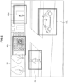
- FIG. 2 is an explanatory diagram illustrating an example of the shrunken image (shrunken image 32).
- the shrunken image 32 includes all regions included in the original image.
- the gaze target region such as a face of a person may be so small in the shrunken image 32, and therefore it may be difficult to see the gaze target region.
- the regions 40 illustrated in FIG. 2 are regions corresponding to cropping regions (to be described later). In general, the cropping region is set within a frame image.
- regions corresponding to the cropping regions in the shrunken image 32 are referred to as the regions 40 for convenience of description.
- FIG. 3 is an explanatory diagram illustrating an example of a plurality of cropped images (a set 52 of the cropped images) generated from one original image.
- the cropped images 50 have the same resolution as the original image, each of the cropped images 50 includes only a partial region of the original image, as illustrated in FIG. 3 .
- the camera 10 basically generates one shrunken image and one or more cropped images from one original image.
- a user can check the entire scene captured by the camera 10 and can check the gaze target region at high resolution.
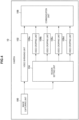
- the camera 10 includes an image capturing unit 100, a video shrinking unit 102, a region setting unit 104, a plurality of video cropping units 106, and a communication unit 108.
- FIG. 4 shows an example in which there are four video cropping units 106, the number of the video cropping units is not limited thereto. For example, there are any number of the video cropping units as long as the minimum number is one.
- the image capturing unit 100 has a function of acquiring the original image by causing an image sensor such as a charge-coupled device (CCD) or a complementary metal-oxide-semiconductor (CMOS) to form an image of video of an outside through a lens.
- an image sensor such as a charge-coupled device (CCD) or a complementary metal-oxide-semiconductor (CMOS) to form an image of video of an outside through a lens.
- CCD charge-coupled device
- CMOS complementary metal-oxide-semiconductor
- the video shrinking unit 102 generates the shrunken image by shrinking the original image acquired by the image capturing unit 100 down to a predetermined size.
- the region setting unit 104 sets a cropping region in the original image acquired by the image capturing unit 100.
- the cropping region is a source region from which a cropped image is to be generated.
- the region setting unit 104 sets the same number of cropping regions as the number of the video cropping units 106 in the camera 10, in the original image acquired by the image capturing unit 100.
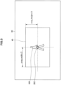
- FIG. 5 is an explanatory diagram illustrating an example in which the region setting unit 104 sets a cropping region. Note that, in FIG. 5 , “crop_width” represents a width of the cropping region, and “crop_height” represents a height of the cropping region.
- the region setting unit 104 detects a detection target object such as a person 300 in the original image 30, and sets the cropping region 40 on the basis of a detection position 302 of the object.
- the video cropping unit 106 is an example of the cutout image generation unit according to the present disclosure.
- the video cropping unit 106 generates a cropped image by cutting out the cropping region set by the region setting unit 104 from the original image acquired by the image capturing unit 100.
- FIG. 3 illustrates four cropped images 50 respectively generated by the four video cropping units 106.
- the video cropping unit 106a generates a cropped image 50a from a cropping region corresponding to a region 40a illustrated in FIG. 2 that is set by the region setting unit 104.
- the video cropping unit 106b generates a cropped image 50b from a cropping region corresponding to a region 40b illustrated in FIG. 2 that is set by the region setting unit 104.
- the communication unit 108 exchanges various kinds of information with devices connected with the communication network 24.
- the communication unit 108 transmits, to the storage 20, the shrunken image acquired by the video shrinking unit 102 and the plurality of cropped images generated by the plurality of video cropping units 106.
- the storage 20 is a storage device configured to store the shrunken image and the cropped images received from the camera 10.
- the storage 20 stores the received shrunken image and the plurality of received cropped images in association with identification information of the camera 10 and image capturing date and time.
- the storage 20 may be installed in a datacenter, a monitoring center where observers are working, or the like.
- the monitoring terminal 22 is an information processing terminal configured to display the shrunken image and the cropped images generated by the camera 10.
- the monitoring terminal 22 may be installed in the monitoring center.
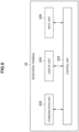
- FIG. 6 is a functional block diagram illustrating the configuration of the monitoring terminal 22 according to the embodiment.
- the monitoring terminal 22 includes a control unit 220, a communication unit 222, a display unit 224, and an input unit 226.
- the control unit 220 controls entire operation of the monitoring terminal 22 by using hardware such as a central processing unit (CPU), random access memory (RAM), and read only memory (ROM) embedded in the monitoring terminal 22.
- hardware such as a central processing unit (CPU), random access memory (RAM), and read only memory (ROM) embedded in the monitoring terminal 22.
- CPU central processing unit
- RAM random access memory
- ROM read only memory
- the communication unit 222 exchanges various kinds of information with devices connected with the communication network 24.
- the communication unit 222 receives, from the storage 20, the shrunken image and the cropped images stored in the storage 20.
- the communication unit 222 may directly receive the shrunken image and the plurality of cropped images generated by the camera 10 from the camera 10.
- the display unit 224 is implemented by a display such as a liquid crystal display (LCD), or an organic light emitting diode (OLED).
- the display unit 224 displays a monitoring screen including the shrunken image and the cropped images received from the storage 20.
- the input unit 226 includes an input device such as a mouse, a keyboard, or a microphone.
- the input unit 226 receives various kinds of input performed by the user on the monitoring terminal 22.
- the communication network 24 is a wired or wireless communication channel through which information is transmitted from devices connected with the communication network 24.
- the communication network 24 may include a public network, various kinds of local area networks (LANs), a wide area network (WAN), and the like.
- the public network includes the Internet, a satellite communication network, a telephone network, and the like, and the LANs include Ethernet (registered trademark).
- the communication network 24 may include a dedicated line network such as an Internet Protocol Virtual Private Network (IP-VPN).
- IP-VPN Internet Protocol Virtual Private Network
- the image processing system is not limited to the above described configurations.
- the storage 20 may be integrated with the monitoring terminal 22.
- the image processing system does not have to include the storage 20 or the monitoring terminal 22.
- the region setting unit 104 sets a cropping region on the basis of the detection position of the object detected in the original image.
- Examples of a method for setting the cropping region include a method for setting a cropping region such that a detection position of a detection target object is at the center of the cropping region. According to this setting method, it is possible to generate the cropped image such that the user can easily see the detection target object in the cropped image.
- FIG. 7 is an explanatory diagram illustrating an example of setting the cropping region 40 such that the detection position 302 of the person 300 is at the center of the cropping region 40.
- a human face is set as a detection target part when detecting a human.
- the facial region of the person 300 is out of the cropping region 40 since the size of the person 300 is extremely larger than the size of the cropping region 40.
- the camera 10 according to the embodiment has been developed in view of the above described circumstance.
- the camera 10 according to the embodiment is capable of setting a cropping region such that a detection target part is included in the cropping region in accordance with the type of a detection target object.
- the region setting unit 104 is one of the features of the camera 10 according to the embodiment. Next, with reference to FIG. 8 , details of the configuration of the region setting unit 104 according to the embodiment will be described.
- the region setting unit 104 includes an object detection unit 120, a detection region calculation unit 122, and a cropping region deciding unit 124.
- the object detection unit 120 detects an object in the original image on the basis of a set detection condition. For example, in the case where a detection mode is set in advance (as the detection condition) in accordance with the type of a detection target object, the object detection unit 120 detects the same number of objects as the number of the video cropping units 106 in the camera 10 or the like, from the original image.
- the types of the objects correspond to the set detection mode.
- the types of the detection target objects may include a human and an automobile.
- the types of the detection target objects may further include a ship, an airplane, a motorcycle, and a bicycle.
- the object detection unit 120 detects regions in which people are captured in the original image.
- the detection mode may be set as a mode for detecting only one type of object, or may be set as a mode for detecting a plurality of types of objects such as "human and automobile detection mode".
- the detection mode may be set or changed by an administrator at any timing, for example.
- a specific detection mode (such as "human detection mode") is set in the camera 10 at the time of development of the camera 10.
- the types of the objects may be classified into a plurality of stages such as a broad category and a narrow category, and different detection modes may be set for classes in different stages.
- the broad category is "automobile”
- the narrow categories include “truck”, “standard-sized car”, and the like.
- a “truck detection mode”, a “standard-sized-car detection mode”, or the like may be set as the detection mode.
- the detection region calculation unit 122 calculates a region size of the object detected by the object detection unit 120. For example, the detection region calculation unit 122 calculates, as the region size of the object, the region size of the object detected in the original image acquired by the image capturing unit 100.
- the detection region calculation unit 122 calculates, as the region size of the object, an average value of region sizes of the object detected in a predetermined number of original images (hereinafter, sometimes referred to as frame images) such as several original images or a few dozen original images that have been captured at the last minute. According to such a calculation example, it is possible to suppress large change in content of cropped images generated from a series of frame images even in the case where the size of the object detected in the series of frame images varies significantly.
- a predetermined number of original images hereinafter, sometimes referred to as frame images
- the detection region calculation unit 122 it is also possible for the detection region calculation unit 122 to calculate the region size of the object by applying an infinite impulse response (IIR) filter, least-squares fitting, or a Kalman filter on a predetermined number of past frame images instead of calculating the average value.
- IIR infinite impulse response
- the average value of the region sizes of the object in the past frame images is smaller than the region size of the object in a current frame image.
- the detection region calculation unit 122 may calculate a final region size of the object by adding a predetermined margin to the region size calculated on the basis of the above described calculation method.
- the detection region calculation unit 122 may calculate a final region size of the object by enlarging the region size calculated on the basis of the above described calculation method to a predetermined percentage such as 110%.
- the detection region calculation unit 122 may calculate a final region size of the object by adding predetermined lengths to the width and the height of the calculated region size of the object.
- the cropping region deciding unit 124 is an example of the cutout region deciding unit according to the present disclosure. On the basis of the size of the object calculated by the detection region calculation unit 122, the cropping region deciding unit 124 decides, as the cropping region, a region positioned in a relative direction based on the detection position of the object in the original image, the relative direction corresponding to the type of the object.
- the cropping region deciding unit 124 calculates a position (correction position) moved from the detection position of the object in the original image by a predetermined distance in the direction corresponding to the type of the object, and decides the cropping region such that the calculated correction position is at the center of the cropping region.
- the camera 10 may store a database in which correspondence relations between types of objects, movement directions (correction directions) of cropping regions, and movement distance calculation formulas are stored.
- the cropping region deciding unit 124 is capable of calculating the correction position by using this database.
- the cropping region deciding unit 124 decides the cropping region such that the detection position of the object in the original image is at the center of the cropping region.
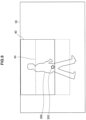
- FIG. 9 is an explanatory diagram illustrating an example of deciding a cropping region in the case where a type of a detection target object is a human.
- a dashed rectangle represents a cropping region 44 decided such that a detection position 302 of a person is at the center of the cropping region 44 (hereinafter, referred to as a standard cropping region 44).
- a solid rectangle represents a cropping region 40 finally decided by the cropping region deciding unit 124.
- the cropping region deciding unit 124 decides the cropping region 40 by moving the standard cropping region 44 in the relative upper direction in the original image 30. For example, in such a case, the cropping region deciding unit 124 first calculates a difference between the height of the upper side of the standard cropping region 44 and the height of the top of the head of the detect person 300. Next, the cropping region deciding unit 124 calculates a position obtained by moving the detection position 302 of the person in the upper direction by the calculated difference or more. Subsequently, the cropping region deciding unit 124 decides the cropping region 40 such that the calculated position is at the center of the cropping region 40.
- the type of the detection target object is a "human”
- a human face is designated as the detection target part in many cases.
- FIG. 10 is an explanatory diagram illustrating an example of a cropped image (cropped image 50) generated by the video cropping unit 106 on the basis of the cropping region 40 illustrated in FIG. 9 .
- the cropped image 50 is generated by the video cropping unit 106 cutting out the cropping region 40 from the original image 30.
- the cropping region deciding unit 124 decides the cropping region 40 by moving the standard cropping region 44 in the relative lower direction in the original image 30. For example, in such a case, the cropping region deciding unit 124 first calculates a difference between the height of the base of the standard cropping region 44 and the height of the bottom of a tire of the detected truck 300. Next, the cropping region deciding unit 124 calculates a position obtained by moving the detection position 302 of the truck in the lower direction by the calculated difference. Subsequently, the cropping region deciding unit 124 decides the cropping region 40 such that the calculated position is at the center of the cropping region 40.
- a vehicle registration plate is designated as the detection target part in many cases.
- the cropping region deciding unit 124 decides the cropping region by moving the position of the standard cropping region in the direction corresponding to the type of the detection target object has been described.
- the present disclosure is not limited thereto.
- the cropping region deciding unit 124 may decide the cropping region by enlarging the size of the standard cropping region in a direction corresponding to the type of a detection target object on the basis of a detection position of the detection target object.
- the cropping region deciding unit 124 may enlarge the standard cropping region 44 in the upper direction by the difference between the height of the upper side of the standard cropping region 44 and the height of the top of the head of the detected person 300 or more, and decide the obtained (rectangular) region as the cropping region.
- the configurations according to the embodiment have been described above.
- operation according to the embodiment will be described. Note that, an operation example will be described in which the camera 10 includes four video cropping units 106 and one shrunken image and four cropped images are generated from one original image.
- FIG. 12 is a flowchart illustrating an operation example according to the embodiment. As illustrated in FIG. 12 , first, the image capturing unit 100 of the camera 10 acquires an original image by capturing video of an outside when a predetermined timing comes (S101).
- the video shrinking unit 102 generates a shrunken image by shrinking the original image acquired in S101 down to a predetermined size (S103).
- the camera 10 performs a "cropped image generation process" (to be described later) the same number of times as the number of the video cropping units 106 (in other words, four times) (S105 to S111).
- the communication unit 108 transmits the shrunken image generated in S103 and four cropped images generated in S107 to the storage 20 (S113).
- the object detection unit 120 of the camera 10 detects a detection target object in the original image acquired in S101, on the basis of a preset detection mode (S151).
- the detection region calculation unit 122 calculates a region size of the object detected in S151. Subsequently, the cropping region deciding unit 124 determines whether the calculated region size is larger than the size of the cropping region (S153).
- the cropping region deciding unit 124 decides that the standard cropping region is used as the cropping region. In other words, the cropping region deciding unit 124 decides the cropping region such that the detection position of the object detected in S151 is at the center of the cropping region (S163). Next, the camera 10 performs operation in S171 to be described later.
- the cropping region deciding unit 124 determines whether the type of the object corresponding to the set detection mode is a human (S155). In the case where the type of the detection target object is a "human" (Yes in S155), the cropping region deciding unit 124 decides the cropping region by moving the standard cropping region in the upper direction in the original image acquired in S101 (S157). Next, the camera 10 performs operation in S171 to be described later.
- the cropping region deciding unit 124 decides the cropping region by moving the standard cropping region in the lower direction in the original image acquired in S101 (S161). Next, the camera 10 performs operation in S171 to be described later.
- the cropping region deciding unit 124 performs operation in S163 described above.
- the video cropping unit 106 generates a cropped image by cutting out the cropping region decided in S157, S161, or S163 from the original image acquired in S101 (S171).
- the camera 10 detects an object from a captured original image, and decides, as a cropping region, a region positioned in a relative direction based on a detection position of the object in the original image, the relative direction varying depending on a detection condition. Therefore, it is possible to change the position of the cutout region depending of the detection condition even if detection positions of objects are the same.
- the camera 10 decides the cropping region such that the correction position obtained by moving the detection position of the object in the original image by a moving distance corresponding to the type of the object in the direction corresponding to the type of the object is at the center of the cropping region. Therefore, it is possible to set the cropping region such that a detection target part of the detection target object is included in the cropping region even in the case where the region size of the detection target object is larger than the size of the cropping region. As a result, visibility of the detection target part (such as human face) in the cropped image can be improved.
- the detection target part such as human face
- the camera 10 can generate cropped images in real time.
- the camera 10 does not have to transmit the original image to another device such as a server to generate the shrunken image and the cropped images, and this enables reducing communication traffic.
- Another problem of the method for setting a cropping region such that a detection position of a detection target object is at the center of the cropping region is that, sometimes a part of the cropping region is out of the original image when the target object is positioned near an edge of the original image.
- a known technology for solving this problem proposes a method for setting a position of a cropping target object at a position different from the center of the cropping region. For example, as illustrated in FIG. 15 , the known technology decides the cropping region 40 such that a part of an edge of the cropping region 40 is identical to a part of an edge of the original image 30.
- the detection target object is not always surely detected, and sometimes the detection fails.
- the position of the object (person) in the original image 30 is generally different from the central position 410 of the cropping region 40 as illustrated in FIG. 16 , for example.
- the known technology includes a problem that a user cannot determine whether detection of a detection target object has failed or the detection target object is near an edge of the original image simply by seeing the cropped image.
- the video cropping unit 106 In the case where a part of the cropping region decided by the cropping region deciding unit 124 is out of the original image, the video cropping unit 106 according to the application example generates a cropped image such that the cropped image includes display showing the region out of the original image. In such a case, the video cropping unit 106 fills the region out of the original image with a predetermined color or a predetermined pattern in the cropped image, for example. In addition, in such a case, the video cropping unit 106 places a predetermined character string in the region out of the original image. In such a generation example, it is possible to clearly show the region out of the original image in the cropped image to a user.
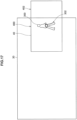
- FIG. 17 is an explanatory diagram illustrating an example of the cropping region 40 decided by the cropping region deciding unit 124 in the case where the person 300 is near an edge of the original image 30.
- the region size of the person 300 is smaller than the size of the cropping region 40. Therefore, the cropping region deciding unit 124 decides the cropping region 40 such that the detection position 302 of the person is at the center of the cropping region 40. As a result, as illustrated in FIG. 17 , a partial region 402 in the cropping region 40 becomes out of the original image 30.
- FIG. 18 is an explanatory diagram illustrating an example of a cropped image (cropped image 50) generated by the video cropping unit 106 in the case where the cropping region 40 is decided as illustrated in FIG. 17 .
- the video cropping unit 106 generates the cropped image 50 such that the cropped image 50 includes a region 500 cut out from the original image 30, and an extruded region 502 that is a region out of the original image 30.
- the cutout region 500 is identical to the region 400 included in the original image 30 in the cropping region 40 illustrated in FIG. 17 .
- the video cropping unit 106 fills the extruded region 502 with a predetermined color, and places a character string such as "Out of sight" in the extruded region 502.
- the character string clearly shows that this region is an extruded region.
- This cropped image 50 can clearly show that the detection of the detection target object has succeeded and the object is near the edge in the original image. In addition, it is also possible to clearly show which of the edges the object is close to in the original image (for example, in the example illustrated in FIG. 18 , the object is close to the right edge of the original image).
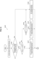
- FIG. 19 is a flowchart illustrating a part of operation of the "cropped image generation process" according to the application example. Note that, operation similar to the operation in S101 to S163 illustrated in FIG. 12 and FIG. 13 according to the embodiment is also used in the application example. In addition, the operation in S201 of FIG. 19 is similar to S171 in FIG. 14 according to the above described embodiment. Hereinafter, operation after S201 will be described.
- the video cropping unit 106 determines whether a part of the cropping region decided in S157, S161, or S163 is out of the original image acquired in S101 (S203) after S201. In the case where the part of the cropping region is not out of the original image (No in S203), the camera 10 finishes the "cropped image generation process".
- the region out of the original image in the cropping region in the cropped image generated in S201 is filled with a predetermined color or a predetermined pattern (S205).
- the camera 10 As described with reference to FIG. 19 and the like, the camera 10 according to the application example generates a cropped image such that the cropped image includes display showing the region out of the original image in the case where the part of the decided cropping region is out of the original image. Therefore, the user can determine whether the detection of the object has failed or the detection of the detection target object has succeeded but the object is near an edge in the original image, simply by seeing the cropped image.
- the user can recognize which of the edges the object is close to, simply by seeing the cropped image.
- the monitoring terminal 22 may serve as the image processing device according to the present disclosure in the case where (the control unit 220 of) the monitoring terminal 22 includes all the video shrinking unit 102, the region setting unit 104, and the plurality of video cropping units 106 instead of the camera 10.
- a separately-provided server may serve as the image processing device according to the present disclosure in the case where the server is capable of communicating with the camera 10 via the communication network 24 and the server includes all the video shrinking unit 102, the region setting unit 104, and the plurality of video cropping units 106 instead of the camera 10.
- the server may be integrated with the storage 20.
- the camera 10 is capable of identifying the type of the object included in the captured original image, and dynamically setting a detection mode corresponding to the identified type.
- the camera 10 in the case where the type of the object included in the captured original image is a human only, it is possible for the camera 10 to identify that the object is a human by calculating a width-height ratio of a detected object region and dynamically set a detection mode (such as a "human detection mode") corresponding to the identification result.
Landscapes
- Engineering & Computer Science (AREA)
- Multimedia (AREA)
- Signal Processing (AREA)
- Computer Vision & Pattern Recognition (AREA)
- Physics & Mathematics (AREA)
- General Physics & Mathematics (AREA)
- Theoretical Computer Science (AREA)
- Image Processing (AREA)
- Closed-Circuit Television Systems (AREA)
- Studio Devices (AREA)
- Image Analysis (AREA)
Claims (12)
- Bildverarbeitungseinrichtung (104), umfassend:eine Objektdetektionseinheit (120), ausgelegt zum Detektieren eines Objekts in einem ersten Bild; undeine Ausschnittsgebiet-Entscheidungseinheit (124), ausgelegt zum Entscheiden eines Ausschnittsgebiets (44) als eine Position, bei der das Objekt in dem ersten Bild detektiert wird, und dann zum Bewegen des Ausschnittsgebiets in eine Richtung entsprechend einem Typ des Objekts, wobeider Typ des Detektionszielobjekts beinhaltet: einen Menschen und ein Kraftfahrzeug; unddie Relativrichtung gemäß dem Typ des Detektionszielobjekts derart variiert, dass, falls der Typ des Detektionszielobjekts ein Mensch ist, das Ausschnittsgebiet in einer ersten Relativrichtung bewegt wird, und falls der Typ des Detektionszielobjekts ein Fahrzeug ist, das Ausschnittsgebiet in einer zweiten Relativrichtung bewegt wird.
- Bildverarbeitungseinrichtung nach Anspruch 1,
wobei in dem Fall, wo das Detektionszielobjekt ein Mensch ist, die Ausschnittsgebiets-Entscheidungseinheit (124) als das Ausschnittsgebiet ein Gebiet entscheidet, das in einer oberen Richtung relativ zu einer Position positioniert ist, bei der der Mensch in dem ersten Bild detektiert wird. - Bildverarbeitungseinrichtung nach Anspruch 1,
wobei in dem Fall, dass das Detektionszielobjekt ein Kraftfahrzeug ist, die Ausschnittsgebiets-Entscheidungseinheit (124) als das Ausschnittsgebiet ein Gebiet entscheidet, das in einer unteren Richtung relativ zu einer Position positioniert ist, bei der das Kraftfahrzeug in dem ersten Bild detektiert wird. - Bildverarbeitungseinrichtung nach Anspruch 1,
wobei die Ausschnittsgebiets-Entscheidungseinheit (124) das Ausschnittsgebiet derart entscheidet, dass eine Position, die erhalten wird durch Bewegen der Position, bei der das Objekt in dem ersten Bild detektiert wird, in einer Relativrichtung, die abhängig von dem Typ des Objekts variiert, auf die Mitte des Ausschnittsgebiets gelegt wird. - Bildverarbeitungseinrichtung nach Anspruch 1, wobeieine Größe des Ausschnittsgebiets im Voraus entschieden wird,die Bildverarbeitungseinrichtung weiter eine Detektionsgebiets-Berechnungseinheit (122) umfasst, die ausgelegt ist zum Berechnen einer Gebietsgröße eines detektierten Objekts, unddie Ausschnittsgebiets-Entscheidungseinheit das Ausschnittsgebiet als Reaktion darauf entscheidet, dass die durch die Detektionsgebiets-Berechnungseinheit (122) berechnete Gebietsgröße größer ist als die Größe des Ausschnittsgebiets.
- Bildverarbeitungseinrichtung nach Anspruch 5, wobeidas erste Bild ein Einzelbild in einem Bewegtbild ist, unddie Detektionsgebiets-Berechnungseinheit (122) die Gebietsgröße des Objekts in dem ersten Bild auf Basis von Gebietsgrößen des in mehreren Einzelbildern vor dem ersten Bild berechneten Objekt berechnet.
- Bildverarbeitungseinrichtung nach Anspruch 1, weiter umfassend
eine Ausschnittsbild-Generierungseinheit, ausgelegt zum Generieren eines Ausschnittsbilds durch Ausschneiden des durch die Ausschnittsgebiet-Entscheidungseinheit (124) entschiedenen Ausschnittsgebiets aus dem ersten Bild. - Bildverarbeitungseinrichtung nach Anspruch 7,
wobei in dem Fall, wo ein Teil des Ausschnittsgebiets, entschieden durch die Ausschnittsgebiet-Entscheidungseinheit (124), sich außerhalb des ersten Bilds befindet, die Ausschnittsbild-Generierungseinheit das Ausschnittsbild derart generiert, das das Ausschnittsbild ein Display zeigt, dass das Gebiet außerhalb des ersten Bilds zeigt. - Bildverarbeitungseinrichtung nach Anspruch 8,
wobei in dem Display, das das Gebiet außerhalb des ersten Bilds zeigt, das Gebiet außerhalb des ersten Bilds mit einer vorbestimmten Farbe oder einem vorbestimmten Muster gefüllt wird. - Bildverarbeitungseinrichtung nach Anspruch 8,
wobei in dem Display, das das Gebiet außerhalb des ersten Bilds zeigt, eine vorbestimmte Zeichenkette in das Gebiet außerhalb des ersten Bilds platziert wird. - Bildverarbeitungsverfahren (S107), umfassend:Detektieren (S151) eines Objekts in einem ersten Bild; undEntscheiden (S155, S159, S157, S161, S163) eines Ausschnittsgebiets an einer Position, bei der das Objekt in dem ersten Bild detektiert wird;Bewegen des Ausschnittsgebiets in einer Richtung entsprechend einem Typ des Objekts, wobeider Typ des Detektionszielobjekts beinhaltet: einen Menschen und ein Kraftfahrzeug; unddie Relativrichtung gemäß dem Typ des Detektionszielobjekts derart variiert, dass, falls der Typ des Detektionszielobjekts ein Mensch ist, das Ausschnittsgebiet in einer ersten Relativrichtung bewegt wird, und falls der Typ des Detektionszielobjekts ein Fahrzeug ist, das Ausschnittsgebiet in einer zweiten Relativrichtung bewegt wird.
- Bildverarbeitungssystem, umfassend:eine Bildverarbeitungseinrichtung nach Anspruch 1,eine Ausschnittsbild-Generierungseinheit, ausgelegt zum Generieren eines Ausschnittsbilds durch Ausschneiden des Ausschnittsbilds, entschieden durch die Ausschnittsgebiet-Entscheidungseinheit, aus dem ersten Bild; undeine Speichereinheit (20), ausgelegt zum Speichern des generierten Ausschnittsbilds.
Applications Claiming Priority (2)
| Application Number | Priority Date | Filing Date | Title |
|---|---|---|---|
| JP2015082273 | 2015-04-14 | ||
| PCT/JP2016/054553 WO2016167017A1 (ja) | 2015-04-14 | 2016-02-17 | 画像処理装置、画像処理方法、および画像処理システム |
Publications (3)
| Publication Number | Publication Date |
|---|---|
| EP3285477A1 EP3285477A1 (de) | 2018-02-21 |
| EP3285477A4 EP3285477A4 (de) | 2018-09-19 |
| EP3285477B1 true EP3285477B1 (de) | 2023-06-28 |
Family
ID=57126149
Family Applications (1)
| Application Number | Title | Priority Date | Filing Date |
|---|---|---|---|
| EP16779809.9A Active EP3285477B1 (de) | 2015-04-14 | 2016-02-17 | Bildverarbeitungsvorrichtung, bildverarbeitungsverfahren und bildverarbeitungssystem |
Country Status (5)
| Country | Link |
|---|---|
| US (1) | US11263769B2 (de) |
| EP (1) | EP3285477B1 (de) |
| JP (1) | JP6724904B2 (de) |
| CN (1) | CN107431762B (de) |
| WO (1) | WO2016167017A1 (de) |
Families Citing this family (14)
| Publication number | Priority date | Publication date | Assignee | Title |
|---|---|---|---|---|
| JP6693509B2 (ja) * | 2015-04-14 | 2020-05-13 | ソニー株式会社 | 画像処理装置、画像処理方法、および画像処理システム |
| US10325390B2 (en) * | 2016-03-31 | 2019-06-18 | Qualcomm Incorporated | Geometric work scheduling with dynamic and probabilistic work trimming |
| JP7521768B2 (ja) * | 2017-02-24 | 2024-07-24 | 国立研究開発法人宇宙航空研究開発機構 | 飛翔体 |
| JP6572500B1 (ja) * | 2018-03-14 | 2019-09-11 | エスゼット ディージェイアイ テクノロジー カンパニー リミテッドSz Dji Technology Co.,Ltd | 画像処理装置、撮像装置、移動体、画像処理方法、及びプログラム |
| JP7216487B2 (ja) | 2018-06-21 | 2023-02-01 | キヤノン株式会社 | 画像処理装置およびその制御方法 |
| JP7347435B2 (ja) * | 2018-09-12 | 2023-09-20 | ソニーグループ株式会社 | 画像処理装置、プログラムおよび画像処理方法 |
| US12073597B2 (en) * | 2019-02-21 | 2024-08-27 | Sony Group Corporation | Information processing device and information processing method |
| US11823715B2 (en) | 2019-03-20 | 2023-11-21 | Sony Group Corporation | Image processing device and image processing method |
| CN112136311B (zh) * | 2019-10-22 | 2022-07-12 | 深圳市大疆创新科技有限公司 | 一种图像处理方法、设备、成像系统及存储介质 |
| CN112954267B (zh) * | 2019-12-11 | 2023-02-07 | 杭州海康威视数字技术股份有限公司 | 一种用于生成报警视频的摄像机 |
| CN113014793A (zh) * | 2019-12-19 | 2021-06-22 | 华为技术有限公司 | 一种视频处理方法及电子设备 |
| US20230114776A1 (en) * | 2020-03-27 | 2023-04-13 | Nec Corporation | Image recognition system, image recognition method, and non-transitory computerreadable medium |
| JP7584907B2 (ja) * | 2020-05-12 | 2024-11-18 | キヤノン株式会社 | 撮像装置および撮像装置の制御方法 |
| JP7800548B2 (ja) * | 2021-07-15 | 2026-01-16 | ソニーグループ株式会社 | 情報処理装置、情報処理方法、プログラム |
Citations (3)
| Publication number | Priority date | Publication date | Assignee | Title |
|---|---|---|---|---|
| US20050025387A1 (en) * | 2003-07-31 | 2005-02-03 | Eastman Kodak Company | Method and computer program product for producing an image of a desired aspect ratio |
| WO2011065960A1 (en) * | 2009-11-30 | 2011-06-03 | Hewlett-Packard Development Company, L.P. | Stabilizing a subject of interest in captured video |
| WO2014097536A1 (en) * | 2012-12-20 | 2014-06-26 | Sony Corporation | Image processing device, image processing method, and recording medium |
Family Cites Families (27)
| Publication number | Priority date | Publication date | Assignee | Title |
|---|---|---|---|---|
| JP4516665B2 (ja) | 2000-05-19 | 2010-08-04 | パナソニック株式会社 | 監視装置 |
| JP2004289516A (ja) * | 2003-03-24 | 2004-10-14 | Konica Minolta Holdings Inc | 画像処理方法、画像処理装置、画像処理プログラム及び画像読取装置 |
| JP2005012764A (ja) * | 2003-05-22 | 2005-01-13 | Casio Comput Co Ltd | データ通信装置、画像送信方法および画像送信プログラム |
| JP4181923B2 (ja) * | 2003-05-29 | 2008-11-19 | キヤノン株式会社 | 撮像装置および撮像装置の制御方法 |
| JP4325385B2 (ja) | 2003-12-09 | 2009-09-02 | 株式会社ニコン | デジタルカメラおよびデジタルカメラの画像取得方法 |
| JP2005184266A (ja) | 2003-12-17 | 2005-07-07 | Olympus Corp | 撮像装置 |
| US20060072847A1 (en) * | 2004-10-01 | 2006-04-06 | Microsoft Corporation | System for automatic image cropping based on image saliency |
| JP2006345134A (ja) * | 2005-06-08 | 2006-12-21 | Tomy Co Ltd | デジタルカメラ |
| WO2008075779A1 (en) * | 2006-12-18 | 2008-06-26 | Fujifilm Corporation | Monitoring system, monitoring method and program |
| JP5150943B2 (ja) * | 2006-12-18 | 2013-02-27 | 富士フイルム株式会社 | 監視システム、監視方法、及びプログラム |
| JP5033412B2 (ja) * | 2006-12-25 | 2012-09-26 | 富士フイルム株式会社 | 監視システム、監視方法、及びプログラム |
| JP2008288797A (ja) * | 2007-05-16 | 2008-11-27 | Nikon Corp | 撮像装置 |
| JP2009089356A (ja) * | 2007-09-10 | 2009-04-23 | Fujifilm Corp | 画像処理装置、画像処理方法、およびプログラム |
| JP5111088B2 (ja) * | 2007-12-14 | 2012-12-26 | 三洋電機株式会社 | 撮像装置及び画像再生装置 |
| US20100074557A1 (en) | 2008-09-25 | 2010-03-25 | Sanyo Electric Co., Ltd. | Image Processing Device And Electronic Appliance |
| JP2010103972A (ja) * | 2008-09-25 | 2010-05-06 | Sanyo Electric Co Ltd | 画像処理装置及び電子機器 |
| JP5237055B2 (ja) * | 2008-11-07 | 2013-07-17 | キヤノン株式会社 | 映像送信装置、映像送信方法、およびコンピュータプログラム |
| JP5302740B2 (ja) * | 2009-04-08 | 2013-10-02 | オリンパスイメージング株式会社 | 画像表示装置 |
| JP5427577B2 (ja) * | 2009-12-04 | 2014-02-26 | パナソニック株式会社 | 表示制御装置及び表示画像形成方法 |
| TWI430185B (zh) * | 2010-06-17 | 2014-03-11 | Inst Information Industry | 臉部表情辨識系統及其辨識方法及其電腦程式產品 |
| JP2012205037A (ja) * | 2011-03-25 | 2012-10-22 | Olympus Imaging Corp | 画像処理装置および画像処理方法 |
| CN102663357A (zh) * | 2012-03-28 | 2012-09-12 | 北京工业大学 | 基于颜色特征的停车场车位检测算法 |
| US9317908B2 (en) * | 2012-06-29 | 2016-04-19 | Behavioral Recognition System, Inc. | Automatic gain control filter in a video analysis system |
| EP2680219A1 (de) * | 2012-06-29 | 2014-01-01 | Thomson Licensing | Verfahren zum Reframing von Bildern einer Videosequenz sowie Vorrichtung zum Reframing von Bildern einer Videosequenz |
| CN102799868B (zh) * | 2012-07-10 | 2014-09-10 | 吉林禹硕动漫游戏科技股份有限公司 | 人脸面部关键表情识别方法 |
| US9087263B2 (en) * | 2013-12-09 | 2015-07-21 | National Chung Shan Institute Of Science And Technology | Vision based pedestrian and cyclist detection method |
| JP6693509B2 (ja) * | 2015-04-14 | 2020-05-13 | ソニー株式会社 | 画像処理装置、画像処理方法、および画像処理システム |
-
2016
- 2016-02-17 WO PCT/JP2016/054553 patent/WO2016167017A1/ja not_active Ceased
- 2016-02-17 CN CN201680019671.XA patent/CN107431762B/zh active Active
- 2016-02-17 EP EP16779809.9A patent/EP3285477B1/de active Active
- 2016-02-17 US US15/559,979 patent/US11263769B2/en active Active
- 2016-02-17 JP JP2017512215A patent/JP6724904B2/ja active Active
Patent Citations (3)
| Publication number | Priority date | Publication date | Assignee | Title |
|---|---|---|---|---|
| US20050025387A1 (en) * | 2003-07-31 | 2005-02-03 | Eastman Kodak Company | Method and computer program product for producing an image of a desired aspect ratio |
| WO2011065960A1 (en) * | 2009-11-30 | 2011-06-03 | Hewlett-Packard Development Company, L.P. | Stabilizing a subject of interest in captured video |
| WO2014097536A1 (en) * | 2012-12-20 | 2014-06-26 | Sony Corporation | Image processing device, image processing method, and recording medium |
Also Published As
| Publication number | Publication date |
|---|---|
| WO2016167017A1 (ja) | 2016-10-20 |
| US20180108144A1 (en) | 2018-04-19 |
| CN107431762A (zh) | 2017-12-01 |
| US11263769B2 (en) | 2022-03-01 |
| JP6724904B2 (ja) | 2020-07-15 |
| JPWO2016167017A1 (ja) | 2018-02-08 |
| EP3285477A1 (de) | 2018-02-21 |
| CN107431762B (zh) | 2020-12-01 |
| EP3285477A4 (de) | 2018-09-19 |
Similar Documents
| Publication | Publication Date | Title |
|---|---|---|
| EP3285477A1 (de) | Bildverarbeitungsvorrichtung, bildverarbeitungsverfahren und bildverarbeitungssystem | |
| EP3588456B1 (de) | Bildverarbeitungsvorrichtung, bildverarbeitungsverfahren und programm | |
| EP3284014B1 (de) | Bildverarbeitungsvorrichtung, bildverarbeitungsverfahren und bildverarbeitungssystem | |
| EP3435667B1 (de) | Überwachungssystem, bildverarbeitungsvorrichtung, bildverarbeitungsverfahren und programmaufzeichnungsmedium | |
| US10762649B2 (en) | Methods and systems for providing selective disparity refinement | |
| JP6584123B2 (ja) | 画像処理装置、画像処理方法、及びプログラム | |
| EP3285476A1 (de) | Bildverarbeitungsvorrichtung, bildverarbeitungsverfahren und bildverarbeitungssystem | |
| US20160335491A1 (en) | Method and device for detecting gathering of objects based on stereo vision as well as non-transitory computer-readable medium | |
| KR20160048140A (ko) | 올-인-포커스 이미지를 생성하기 위한 방법 및 장치 | |
| EP2555163B1 (de) | Bildverarbeitungsvorrichtung, Bildverarbeitungsverfahren und Programm | |
| US20150116355A1 (en) | Reference image slicing | |
| KR102156024B1 (ko) | 영상 인식을 위한 그림자 제거 방법 및 이를 위한 그림자 제거 장치 | |
| JP6577397B2 (ja) | 画像解析装置、画像解析方法、画像解析プログラム、および画像解析システム | |
| US10936876B2 (en) | Content recognition method, system and storage medium thereof | |
| CN112446241B (zh) | 用于获得目标对象的特征信息的方法、装置及电子设备 | |
| CN110505438B (zh) | 一种排队数据的获取方法和摄像机 | |
| US9710911B2 (en) | System and method for generating a background reference image from a series of images to facilitate moving object identification | |
| CN106096493A (zh) | 使用深度学习的棒状像素估计和道路场景分割 | |
| JP5142416B2 (ja) | 物体検出装置 | |
| JP2007300531A (ja) | 物体検出装置 | |
| US20140147011A1 (en) | Object removal detection using 3-d depth information | |
| US9842406B2 (en) | System and method for determining colors of foreground, and computer readable recording medium therefor | |
| KR20140143918A (ko) | 영상의 전경과 배경을 분리하여 전경영상을 검출하는 방법 및 장치 | |
| KR20150060032A (ko) | 움직임 검출 시스템 및 방법 | |
| CN117392634B (zh) | 车道线的获取方法、装置、存储介质及电子装置 |
Legal Events
| Date | Code | Title | Description |
|---|---|---|---|
| STAA | Information on the status of an ep patent application or granted ep patent |
Free format text: STATUS: THE INTERNATIONAL PUBLICATION HAS BEEN MADE |
|
| PUAI | Public reference made under article 153(3) epc to a published international application that has entered the european phase |
Free format text: ORIGINAL CODE: 0009012 |
|
| STAA | Information on the status of an ep patent application or granted ep patent |
Free format text: STATUS: REQUEST FOR EXAMINATION WAS MADE |
|
| 17P | Request for examination filed |
Effective date: 20171007 |
|
| AK | Designated contracting states |
Kind code of ref document: A1 Designated state(s): AL AT BE BG CH CY CZ DE DK EE ES FI FR GB GR HR HU IE IS IT LI LT LU LV MC MK MT NL NO PL PT RO RS SE SI SK SM TR |
|
| AX | Request for extension of the european patent |
Extension state: BA ME |
|
| DAV | Request for validation of the european patent (deleted) | ||
| DAX | Request for extension of the european patent (deleted) | ||
| A4 | Supplementary search report drawn up and despatched |
Effective date: 20180820 |
|
| RIC1 | Information provided on ipc code assigned before grant |
Ipc: H04N 5/225 20060101ALI20180813BHEP Ipc: G06T 7/70 20170101ALI20180813BHEP Ipc: H04N 5/232 20060101AFI20180813BHEP Ipc: H04N 7/18 20060101ALI20180813BHEP Ipc: G06T 7/11 20170101ALI20180813BHEP |
|
| STAA | Information on the status of an ep patent application or granted ep patent |
Free format text: STATUS: EXAMINATION IS IN PROGRESS |
|
| 17Q | First examination report despatched |
Effective date: 20190724 |
|
| RAP3 | Party data changed (applicant data changed or rights of an application transferred) |
Owner name: SONY GROUP CORPORATION |
|
| REG | Reference to a national code |
Ref country code: DE Ref legal event code: R079 Free format text: PREVIOUS MAIN CLASS: H04N0005232000 Ipc: H04N0007180000 Ref country code: DE Ref legal event code: R079 Ref document number: 602016080644 Country of ref document: DE Free format text: PREVIOUS MAIN CLASS: H04N0005232000 Ipc: H04N0007180000 |
|
| GRAP | Despatch of communication of intention to grant a patent |
Free format text: ORIGINAL CODE: EPIDOSNIGR1 |
|
| STAA | Information on the status of an ep patent application or granted ep patent |
Free format text: STATUS: GRANT OF PATENT IS INTENDED |
|
| RIC1 | Information provided on ipc code assigned before grant |
Ipc: H04N 23/661 20230101ALI20230109BHEP Ipc: H04N 23/63 20230101ALI20230109BHEP Ipc: H04N 23/61 20230101ALI20230109BHEP Ipc: H04N 23/00 20230101ALI20230109BHEP Ipc: G06T 7/11 20170101ALI20230109BHEP Ipc: G06T 7/70 20170101ALI20230109BHEP Ipc: H04N 7/18 19680901AFI20230109BHEP |
|
| INTG | Intention to grant announced |
Effective date: 20230201 |
|
| GRAS | Grant fee paid |
Free format text: ORIGINAL CODE: EPIDOSNIGR3 |
|
| GRAA | (expected) grant |
Free format text: ORIGINAL CODE: 0009210 |
|
| STAA | Information on the status of an ep patent application or granted ep patent |
Free format text: STATUS: THE PATENT HAS BEEN GRANTED |
|
| AK | Designated contracting states |
Kind code of ref document: B1 Designated state(s): AL AT BE BG CH CY CZ DE DK EE ES FI FR GB GR HR HU IE IS IT LI LT LU LV MC MK MT NL NO PL PT RO RS SE SI SK SM TR |
|
| REG | Reference to a national code |
Ref country code: CH Ref legal event code: EP |
|
| REG | Reference to a national code |
Ref country code: AT Ref legal event code: REF Ref document number: 1583782 Country of ref document: AT Kind code of ref document: T Effective date: 20230715 |
|
| REG | Reference to a national code |
Ref country code: IE Ref legal event code: FG4D |
|
| REG | Reference to a national code |
Ref country code: DE Ref legal event code: R096 Ref document number: 602016080644 Country of ref document: DE |
|
| REG | Reference to a national code |
Ref country code: LT Ref legal event code: MG9D |
|
| PG25 | Lapsed in a contracting state [announced via postgrant information from national office to epo] |
Ref country code: SE Free format text: LAPSE BECAUSE OF FAILURE TO SUBMIT A TRANSLATION OF THE DESCRIPTION OR TO PAY THE FEE WITHIN THE PRESCRIBED TIME-LIMIT Effective date: 20230628 Ref country code: NO Free format text: LAPSE BECAUSE OF FAILURE TO SUBMIT A TRANSLATION OF THE DESCRIPTION OR TO PAY THE FEE WITHIN THE PRESCRIBED TIME-LIMIT Effective date: 20230928 |
|
| REG | Reference to a national code |
Ref country code: NL Ref legal event code: MP Effective date: 20230628 |
|
| REG | Reference to a national code |
Ref country code: AT Ref legal event code: MK05 Ref document number: 1583782 Country of ref document: AT Kind code of ref document: T Effective date: 20230628 |
|
| PG25 | Lapsed in a contracting state [announced via postgrant information from national office to epo] |
Ref country code: RS Free format text: LAPSE BECAUSE OF FAILURE TO SUBMIT A TRANSLATION OF THE DESCRIPTION OR TO PAY THE FEE WITHIN THE PRESCRIBED TIME-LIMIT Effective date: 20230628 Ref country code: NL Free format text: LAPSE BECAUSE OF FAILURE TO SUBMIT A TRANSLATION OF THE DESCRIPTION OR TO PAY THE FEE WITHIN THE PRESCRIBED TIME-LIMIT Effective date: 20230628 Ref country code: LV Free format text: LAPSE BECAUSE OF FAILURE TO SUBMIT A TRANSLATION OF THE DESCRIPTION OR TO PAY THE FEE WITHIN THE PRESCRIBED TIME-LIMIT Effective date: 20230628 Ref country code: LT Free format text: LAPSE BECAUSE OF FAILURE TO SUBMIT A TRANSLATION OF THE DESCRIPTION OR TO PAY THE FEE WITHIN THE PRESCRIBED TIME-LIMIT Effective date: 20230628 Ref country code: HR Free format text: LAPSE BECAUSE OF FAILURE TO SUBMIT A TRANSLATION OF THE DESCRIPTION OR TO PAY THE FEE WITHIN THE PRESCRIBED TIME-LIMIT Effective date: 20230628 Ref country code: GR Free format text: LAPSE BECAUSE OF FAILURE TO SUBMIT A TRANSLATION OF THE DESCRIPTION OR TO PAY THE FEE WITHIN THE PRESCRIBED TIME-LIMIT Effective date: 20230929 |
|
| PG25 | Lapsed in a contracting state [announced via postgrant information from national office to epo] |
Ref country code: FI Free format text: LAPSE BECAUSE OF FAILURE TO SUBMIT A TRANSLATION OF THE DESCRIPTION OR TO PAY THE FEE WITHIN THE PRESCRIBED TIME-LIMIT Effective date: 20230628 |
|
| PG25 | Lapsed in a contracting state [announced via postgrant information from national office to epo] |
Ref country code: SK Free format text: LAPSE BECAUSE OF FAILURE TO SUBMIT A TRANSLATION OF THE DESCRIPTION OR TO PAY THE FEE WITHIN THE PRESCRIBED TIME-LIMIT Effective date: 20230628 |
|
| PG25 | Lapsed in a contracting state [announced via postgrant information from national office to epo] |
Ref country code: ES Free format text: LAPSE BECAUSE OF FAILURE TO SUBMIT A TRANSLATION OF THE DESCRIPTION OR TO PAY THE FEE WITHIN THE PRESCRIBED TIME-LIMIT Effective date: 20230628 |
|
| PG25 | Lapsed in a contracting state [announced via postgrant information from national office to epo] |
Ref country code: IS Free format text: LAPSE BECAUSE OF FAILURE TO SUBMIT A TRANSLATION OF THE DESCRIPTION OR TO PAY THE FEE WITHIN THE PRESCRIBED TIME-LIMIT Effective date: 20231028 |
|
| PG25 | Lapsed in a contracting state [announced via postgrant information from national office to epo] |
Ref country code: SM Free format text: LAPSE BECAUSE OF FAILURE TO SUBMIT A TRANSLATION OF THE DESCRIPTION OR TO PAY THE FEE WITHIN THE PRESCRIBED TIME-LIMIT Effective date: 20230628 Ref country code: SK Free format text: LAPSE BECAUSE OF FAILURE TO SUBMIT A TRANSLATION OF THE DESCRIPTION OR TO PAY THE FEE WITHIN THE PRESCRIBED TIME-LIMIT Effective date: 20230628 Ref country code: RO Free format text: LAPSE BECAUSE OF FAILURE TO SUBMIT A TRANSLATION OF THE DESCRIPTION OR TO PAY THE FEE WITHIN THE PRESCRIBED TIME-LIMIT Effective date: 20230628 Ref country code: PT Free format text: LAPSE BECAUSE OF FAILURE TO SUBMIT A TRANSLATION OF THE DESCRIPTION OR TO PAY THE FEE WITHIN THE PRESCRIBED TIME-LIMIT Effective date: 20231030 Ref country code: IS Free format text: LAPSE BECAUSE OF FAILURE TO SUBMIT A TRANSLATION OF THE DESCRIPTION OR TO PAY THE FEE WITHIN THE PRESCRIBED TIME-LIMIT Effective date: 20231028 Ref country code: ES Free format text: LAPSE BECAUSE OF FAILURE TO SUBMIT A TRANSLATION OF THE DESCRIPTION OR TO PAY THE FEE WITHIN THE PRESCRIBED TIME-LIMIT Effective date: 20230628 Ref country code: EE Free format text: LAPSE BECAUSE OF FAILURE TO SUBMIT A TRANSLATION OF THE DESCRIPTION OR TO PAY THE FEE WITHIN THE PRESCRIBED TIME-LIMIT Effective date: 20230628 Ref country code: CZ Free format text: LAPSE BECAUSE OF FAILURE TO SUBMIT A TRANSLATION OF THE DESCRIPTION OR TO PAY THE FEE WITHIN THE PRESCRIBED TIME-LIMIT Effective date: 20230628 Ref country code: AT Free format text: LAPSE BECAUSE OF FAILURE TO SUBMIT A TRANSLATION OF THE DESCRIPTION OR TO PAY THE FEE WITHIN THE PRESCRIBED TIME-LIMIT Effective date: 20230628 |
|
| PG25 | Lapsed in a contracting state [announced via postgrant information from national office to epo] |
Ref country code: PL Free format text: LAPSE BECAUSE OF FAILURE TO SUBMIT A TRANSLATION OF THE DESCRIPTION OR TO PAY THE FEE WITHIN THE PRESCRIBED TIME-LIMIT Effective date: 20230628 |
|
| REG | Reference to a national code |
Ref country code: DE Ref legal event code: R097 Ref document number: 602016080644 Country of ref document: DE |
|
| PG25 | Lapsed in a contracting state [announced via postgrant information from national office to epo] |
Ref country code: DK Free format text: LAPSE BECAUSE OF FAILURE TO SUBMIT A TRANSLATION OF THE DESCRIPTION OR TO PAY THE FEE WITHIN THE PRESCRIBED TIME-LIMIT Effective date: 20230628 |
|
| PLBE | No opposition filed within time limit |
Free format text: ORIGINAL CODE: 0009261 |
|
| STAA | Information on the status of an ep patent application or granted ep patent |
Free format text: STATUS: NO OPPOSITION FILED WITHIN TIME LIMIT |
|
| PG25 | Lapsed in a contracting state [announced via postgrant information from national office to epo] |
Ref country code: IT Free format text: LAPSE BECAUSE OF FAILURE TO SUBMIT A TRANSLATION OF THE DESCRIPTION OR TO PAY THE FEE WITHIN THE PRESCRIBED TIME-LIMIT Effective date: 20230628 |
|
| 26N | No opposition filed |
Effective date: 20240402 |
|
| PG25 | Lapsed in a contracting state [announced via postgrant information from national office to epo] |
Ref country code: SI Free format text: LAPSE BECAUSE OF FAILURE TO SUBMIT A TRANSLATION OF THE DESCRIPTION OR TO PAY THE FEE WITHIN THE PRESCRIBED TIME-LIMIT Effective date: 20230628 |
|
| PG25 | Lapsed in a contracting state [announced via postgrant information from national office to epo] |
Ref country code: MC Free format text: LAPSE BECAUSE OF FAILURE TO SUBMIT A TRANSLATION OF THE DESCRIPTION OR TO PAY THE FEE WITHIN THE PRESCRIBED TIME-LIMIT Effective date: 20230628 |
|
| REG | Reference to a national code |
Ref country code: CH Ref legal event code: PL |
|
| PG25 | Lapsed in a contracting state [announced via postgrant information from national office to epo] |
Ref country code: LU Free format text: LAPSE BECAUSE OF NON-PAYMENT OF DUE FEES Effective date: 20240217 |
|
| PG25 | Lapsed in a contracting state [announced via postgrant information from national office to epo] |
Ref country code: CH Free format text: LAPSE BECAUSE OF NON-PAYMENT OF DUE FEES Effective date: 20240229 |
|
| PG25 | Lapsed in a contracting state [announced via postgrant information from national office to epo] |
Ref country code: LU Free format text: LAPSE BECAUSE OF NON-PAYMENT OF DUE FEES Effective date: 20240217 Ref country code: CH Free format text: LAPSE BECAUSE OF NON-PAYMENT OF DUE FEES Effective date: 20240229 |
|
| PG25 | Lapsed in a contracting state [announced via postgrant information from national office to epo] |
Ref country code: BG Free format text: LAPSE BECAUSE OF FAILURE TO SUBMIT A TRANSLATION OF THE DESCRIPTION OR TO PAY THE FEE WITHIN THE PRESCRIBED TIME-LIMIT Effective date: 20230628 |
|
| PG25 | Lapsed in a contracting state [announced via postgrant information from national office to epo] |
Ref country code: BG Free format text: LAPSE BECAUSE OF FAILURE TO SUBMIT A TRANSLATION OF THE DESCRIPTION OR TO PAY THE FEE WITHIN THE PRESCRIBED TIME-LIMIT Effective date: 20230628 |
|
| REG | Reference to a national code |
Ref country code: BE Ref legal event code: MM Effective date: 20240229 |
|
| PG25 | Lapsed in a contracting state [announced via postgrant information from national office to epo] |
Ref country code: BE Free format text: LAPSE BECAUSE OF NON-PAYMENT OF DUE FEES Effective date: 20240229 |
|
| PG25 | Lapsed in a contracting state [announced via postgrant information from national office to epo] |
Ref country code: FR Free format text: LAPSE BECAUSE OF NON-PAYMENT OF DUE FEES Effective date: 20240229 |
|
| PG25 | Lapsed in a contracting state [announced via postgrant information from national office to epo] |
Ref country code: IE Free format text: LAPSE BECAUSE OF NON-PAYMENT OF DUE FEES Effective date: 20240217 |
|
| PG25 | Lapsed in a contracting state [announced via postgrant information from national office to epo] |
Ref country code: IE Free format text: LAPSE BECAUSE OF NON-PAYMENT OF DUE FEES Effective date: 20240217 Ref country code: FR Free format text: LAPSE BECAUSE OF NON-PAYMENT OF DUE FEES Effective date: 20240229 Ref country code: BE Free format text: LAPSE BECAUSE OF NON-PAYMENT OF DUE FEES Effective date: 20240229 |
|
| PG25 | Lapsed in a contracting state [announced via postgrant information from national office to epo] |
Ref country code: CY Free format text: LAPSE BECAUSE OF FAILURE TO SUBMIT A TRANSLATION OF THE DESCRIPTION OR TO PAY THE FEE WITHIN THE PRESCRIBED TIME-LIMIT; INVALID AB INITIO Effective date: 20160217 |
|
| PG25 | Lapsed in a contracting state [announced via postgrant information from national office to epo] |
Ref country code: HU Free format text: LAPSE BECAUSE OF FAILURE TO SUBMIT A TRANSLATION OF THE DESCRIPTION OR TO PAY THE FEE WITHIN THE PRESCRIBED TIME-LIMIT; INVALID AB INITIO Effective date: 20160217 |
|
| PG25 | Lapsed in a contracting state [announced via postgrant information from national office to epo] |
Ref country code: TR Free format text: LAPSE BECAUSE OF FAILURE TO SUBMIT A TRANSLATION OF THE DESCRIPTION OR TO PAY THE FEE WITHIN THE PRESCRIBED TIME-LIMIT Effective date: 20230628 |
|
| P01 | Opt-out of the competence of the unified patent court (upc) registered |
Free format text: CASE NUMBER: UPC_APP_0013426_3285477/2025 Effective date: 20251113 |
|
| PGFP | Annual fee paid to national office [announced via postgrant information from national office to epo] |
Ref country code: GB Payment date: 20260121 Year of fee payment: 11 |
|
| PGFP | Annual fee paid to national office [announced via postgrant information from national office to epo] |
Ref country code: DE Payment date: 20260121 Year of fee payment: 11 |