EP3283813B1 - Tank mit einer wand mit einer spezifischen zone für den durchgang eines durchgangselements - Google Patents
Tank mit einer wand mit einer spezifischen zone für den durchgang eines durchgangselements Download PDFInfo
- Publication number
- EP3283813B1 EP3283813B1 EP16733131.3A EP16733131A EP3283813B1 EP 3283813 B1 EP3283813 B1 EP 3283813B1 EP 16733131 A EP16733131 A EP 16733131A EP 3283813 B1 EP3283813 B1 EP 3283813B1
- Authority
- EP
- European Patent Office
- Prior art keywords
- primary
- tank
- insulating panels
- insulating
- panels
- Prior art date
- Legal status (The legal status is an assumption and is not a legal conclusion. Google has not performed a legal analysis and makes no representation as to the accuracy of the status listed.)
- Active
Links
- 229910052751 metal Inorganic materials 0.000 claims description 96
- 239000002184 metal Substances 0.000 claims description 96
- 239000012528 membrane Substances 0.000 claims description 86
- 230000004888 barrier function Effects 0.000 claims description 66
- 239000012530 fluid Substances 0.000 claims description 23
- 238000007789 sealing Methods 0.000 claims description 20
- 238000003860 storage Methods 0.000 claims description 17
- 238000009434 installation Methods 0.000 claims description 13
- 238000004873 anchoring Methods 0.000 claims description 10
- 238000007667 floating Methods 0.000 claims description 10
- 230000000284 resting effect Effects 0.000 claims description 5
- 230000000717 retained effect Effects 0.000 claims description 5
- 238000000034 method Methods 0.000 claims description 2
- 238000004078 waterproofing Methods 0.000 description 50
- 239000003949 liquefied natural gas Substances 0.000 description 19
- 238000009413 insulation Methods 0.000 description 18
- 239000006260 foam Substances 0.000 description 9
- 229920000642 polymer Polymers 0.000 description 7
- 239000007789 gas Substances 0.000 description 4
- 239000011810 insulating material Substances 0.000 description 4
- 239000011120 plywood Substances 0.000 description 3
- IJGRMHOSHXDMSA-UHFFFAOYSA-N Atomic nitrogen Chemical compound N#N IJGRMHOSHXDMSA-UHFFFAOYSA-N 0.000 description 2
- 235000005921 Cynara humilis Nutrition 0.000 description 2
- 240000002228 Cynara humilis Species 0.000 description 2
- 229910000640 Fe alloy Inorganic materials 0.000 description 2
- PXHVJJICTQNCMI-UHFFFAOYSA-N Nickel Chemical compound [Ni] PXHVJJICTQNCMI-UHFFFAOYSA-N 0.000 description 2
- 229910052782 aluminium Inorganic materials 0.000 description 2
- XAGFODPZIPBFFR-UHFFFAOYSA-N aluminium Chemical compound [Al] XAGFODPZIPBFFR-UHFFFAOYSA-N 0.000 description 2
- 210000004027 cell Anatomy 0.000 description 2
- 230000000694 effects Effects 0.000 description 2
- 238000001704 evaporation Methods 0.000 description 2
- 230000008020 evaporation Effects 0.000 description 2
- 239000012212 insulator Substances 0.000 description 2
- 238000004519 manufacturing process Methods 0.000 description 2
- 238000000926 separation method Methods 0.000 description 2
- 239000010935 stainless steel Substances 0.000 description 2
- 229910001220 stainless steel Inorganic materials 0.000 description 2
- 230000000930 thermomechanical effect Effects 0.000 description 2
- OTMSDBZUPAUEDD-UHFFFAOYSA-N Ethane Chemical compound CC OTMSDBZUPAUEDD-UHFFFAOYSA-N 0.000 description 1
- 229910001374 Invar Inorganic materials 0.000 description 1
- PWHULOQIROXLJO-UHFFFAOYSA-N Manganese Chemical compound [Mn] PWHULOQIROXLJO-UHFFFAOYSA-N 0.000 description 1
- 229910000990 Ni alloy Inorganic materials 0.000 description 1
- 230000004308 accommodation Effects 0.000 description 1
- 239000000853 adhesive Substances 0.000 description 1
- 230000001070 adhesive effect Effects 0.000 description 1
- 230000015572 biosynthetic process Effects 0.000 description 1
- 239000000969 carrier Substances 0.000 description 1
- 230000008602 contraction Effects 0.000 description 1
- 238000005520 cutting process Methods 0.000 description 1
- 238000007872 degassing Methods 0.000 description 1
- 238000009826 distribution Methods 0.000 description 1
- 239000000284 extract Substances 0.000 description 1
- 238000011010 flushing procedure Methods 0.000 description 1
- 239000003365 glass fiber Substances 0.000 description 1
- 239000011491 glass wool Substances 0.000 description 1
- 229910052748 manganese Inorganic materials 0.000 description 1
- 239000011572 manganese Substances 0.000 description 1
- 238000005259 measurement Methods 0.000 description 1
- 239000011490 mineral wool Substances 0.000 description 1
- 229910052757 nitrogen Inorganic materials 0.000 description 1
- 238000005192 partition Methods 0.000 description 1
- 229920002635 polyurethane Polymers 0.000 description 1
- 239000004814 polyurethane Substances 0.000 description 1
- 239000011148 porous material Substances 0.000 description 1
- 239000011347 resin Substances 0.000 description 1
- 229920005989 resin Polymers 0.000 description 1
- XLYOFNOQVPJJNP-UHFFFAOYSA-N water Substances O XLYOFNOQVPJJNP-UHFFFAOYSA-N 0.000 description 1
Images


Classifications
-
- F—MECHANICAL ENGINEERING; LIGHTING; HEATING; WEAPONS; BLASTING
- F17—STORING OR DISTRIBUTING GASES OR LIQUIDS
- F17C—VESSELS FOR CONTAINING OR STORING COMPRESSED, LIQUEFIED OR SOLIDIFIED GASES; FIXED-CAPACITY GAS-HOLDERS; FILLING VESSELS WITH, OR DISCHARGING FROM VESSELS, COMPRESSED, LIQUEFIED, OR SOLIDIFIED GASES
- F17C3/00—Vessels not under pressure
- F17C3/02—Vessels not under pressure with provision for thermal insulation
- F17C3/025—Bulk storage in barges or on ships
- F17C3/027—Wallpanels for so-called membrane tanks
-
- B—PERFORMING OPERATIONS; TRANSPORTING
- B63—SHIPS OR OTHER WATERBORNE VESSELS; RELATED EQUIPMENT
- B63B—SHIPS OR OTHER WATERBORNE VESSELS; EQUIPMENT FOR SHIPPING
- B63B25/00—Load-accommodating arrangements, e.g. stowing, trimming; Vessels characterised thereby
- B63B25/02—Load-accommodating arrangements, e.g. stowing, trimming; Vessels characterised thereby for bulk goods
- B63B25/08—Load-accommodating arrangements, e.g. stowing, trimming; Vessels characterised thereby for bulk goods fluid
- B63B25/12—Load-accommodating arrangements, e.g. stowing, trimming; Vessels characterised thereby for bulk goods fluid closed
- B63B25/16—Load-accommodating arrangements, e.g. stowing, trimming; Vessels characterised thereby for bulk goods fluid closed heat-insulated
-
- B—PERFORMING OPERATIONS; TRANSPORTING
- B63—SHIPS OR OTHER WATERBORNE VESSELS; RELATED EQUIPMENT
- B63B—SHIPS OR OTHER WATERBORNE VESSELS; EQUIPMENT FOR SHIPPING
- B63B27/00—Arrangement of ship-based loading or unloading equipment for cargo or passengers
- B63B27/24—Arrangement of ship-based loading or unloading equipment for cargo or passengers of pipe-lines
-
- F—MECHANICAL ENGINEERING; LIGHTING; HEATING; WEAPONS; BLASTING
- F17—STORING OR DISTRIBUTING GASES OR LIQUIDS
- F17C—VESSELS FOR CONTAINING OR STORING COMPRESSED, LIQUEFIED OR SOLIDIFIED GASES; FIXED-CAPACITY GAS-HOLDERS; FILLING VESSELS WITH, OR DISCHARGING FROM VESSELS, COMPRESSED, LIQUEFIED, OR SOLIDIFIED GASES
- F17C3/00—Vessels not under pressure
- F17C3/02—Vessels not under pressure with provision for thermal insulation
- F17C3/04—Vessels not under pressure with provision for thermal insulation by insulating layers
-
- F—MECHANICAL ENGINEERING; LIGHTING; HEATING; WEAPONS; BLASTING
- F17—STORING OR DISTRIBUTING GASES OR LIQUIDS
- F17C—VESSELS FOR CONTAINING OR STORING COMPRESSED, LIQUEFIED OR SOLIDIFIED GASES; FIXED-CAPACITY GAS-HOLDERS; FILLING VESSELS WITH, OR DISCHARGING FROM VESSELS, COMPRESSED, LIQUEFIED, OR SOLIDIFIED GASES
- F17C6/00—Methods and apparatus for filling vessels not under pressure with liquefied or solidified gases
-
- F—MECHANICAL ENGINEERING; LIGHTING; HEATING; WEAPONS; BLASTING
- F17—STORING OR DISTRIBUTING GASES OR LIQUIDS
- F17C—VESSELS FOR CONTAINING OR STORING COMPRESSED, LIQUEFIED OR SOLIDIFIED GASES; FIXED-CAPACITY GAS-HOLDERS; FILLING VESSELS WITH, OR DISCHARGING FROM VESSELS, COMPRESSED, LIQUEFIED, OR SOLIDIFIED GASES
- F17C2201/00—Vessel construction, in particular geometry, arrangement or size
- F17C2201/01—Shape
- F17C2201/0147—Shape complex
- F17C2201/0157—Polygonal
-
- F—MECHANICAL ENGINEERING; LIGHTING; HEATING; WEAPONS; BLASTING
- F17—STORING OR DISTRIBUTING GASES OR LIQUIDS
- F17C—VESSELS FOR CONTAINING OR STORING COMPRESSED, LIQUEFIED OR SOLIDIFIED GASES; FIXED-CAPACITY GAS-HOLDERS; FILLING VESSELS WITH, OR DISCHARGING FROM VESSELS, COMPRESSED, LIQUEFIED, OR SOLIDIFIED GASES
- F17C2201/00—Vessel construction, in particular geometry, arrangement or size
- F17C2201/05—Size
- F17C2201/052—Size large (>1000 m3)
-
- F—MECHANICAL ENGINEERING; LIGHTING; HEATING; WEAPONS; BLASTING
- F17—STORING OR DISTRIBUTING GASES OR LIQUIDS
- F17C—VESSELS FOR CONTAINING OR STORING COMPRESSED, LIQUEFIED OR SOLIDIFIED GASES; FIXED-CAPACITY GAS-HOLDERS; FILLING VESSELS WITH, OR DISCHARGING FROM VESSELS, COMPRESSED, LIQUEFIED, OR SOLIDIFIED GASES
- F17C2203/00—Vessel construction, in particular walls or details thereof
- F17C2203/03—Thermal insulations
- F17C2203/0304—Thermal insulations by solid means
- F17C2203/0329—Foam
- F17C2203/0333—Polyurethane
-
- F—MECHANICAL ENGINEERING; LIGHTING; HEATING; WEAPONS; BLASTING
- F17—STORING OR DISTRIBUTING GASES OR LIQUIDS
- F17C—VESSELS FOR CONTAINING OR STORING COMPRESSED, LIQUEFIED OR SOLIDIFIED GASES; FIXED-CAPACITY GAS-HOLDERS; FILLING VESSELS WITH, OR DISCHARGING FROM VESSELS, COMPRESSED, LIQUEFIED, OR SOLIDIFIED GASES
- F17C2203/00—Vessel construction, in particular walls or details thereof
- F17C2203/03—Thermal insulations
- F17C2203/0304—Thermal insulations by solid means
- F17C2203/0345—Fibres
- F17C2203/035—Glass wool
-
- F—MECHANICAL ENGINEERING; LIGHTING; HEATING; WEAPONS; BLASTING
- F17—STORING OR DISTRIBUTING GASES OR LIQUIDS
- F17C—VESSELS FOR CONTAINING OR STORING COMPRESSED, LIQUEFIED OR SOLIDIFIED GASES; FIXED-CAPACITY GAS-HOLDERS; FILLING VESSELS WITH, OR DISCHARGING FROM VESSELS, COMPRESSED, LIQUEFIED, OR SOLIDIFIED GASES
- F17C2203/00—Vessel construction, in particular walls or details thereof
- F17C2203/03—Thermal insulations
- F17C2203/0304—Thermal insulations by solid means
- F17C2203/0358—Thermal insulations by solid means in form of panels
-
- F—MECHANICAL ENGINEERING; LIGHTING; HEATING; WEAPONS; BLASTING
- F17—STORING OR DISTRIBUTING GASES OR LIQUIDS
- F17C—VESSELS FOR CONTAINING OR STORING COMPRESSED, LIQUEFIED OR SOLIDIFIED GASES; FIXED-CAPACITY GAS-HOLDERS; FILLING VESSELS WITH, OR DISCHARGING FROM VESSELS, COMPRESSED, LIQUEFIED, OR SOLIDIFIED GASES
- F17C2203/00—Vessel construction, in particular walls or details thereof
- F17C2203/03—Thermal insulations
- F17C2203/0375—Thermal insulations by gas
- F17C2203/0379—Inert
-
- F—MECHANICAL ENGINEERING; LIGHTING; HEATING; WEAPONS; BLASTING
- F17—STORING OR DISTRIBUTING GASES OR LIQUIDS
- F17C—VESSELS FOR CONTAINING OR STORING COMPRESSED, LIQUEFIED OR SOLIDIFIED GASES; FIXED-CAPACITY GAS-HOLDERS; FILLING VESSELS WITH, OR DISCHARGING FROM VESSELS, COMPRESSED, LIQUEFIED, OR SOLIDIFIED GASES
- F17C2203/00—Vessel construction, in particular walls or details thereof
- F17C2203/06—Materials for walls or layers thereof; Properties or structures of walls or their materials
- F17C2203/0602—Wall structures; Special features thereof
- F17C2203/0612—Wall structures
- F17C2203/0626—Multiple walls
- F17C2203/0631—Three or more walls
-
- F—MECHANICAL ENGINEERING; LIGHTING; HEATING; WEAPONS; BLASTING
- F17—STORING OR DISTRIBUTING GASES OR LIQUIDS
- F17C—VESSELS FOR CONTAINING OR STORING COMPRESSED, LIQUEFIED OR SOLIDIFIED GASES; FIXED-CAPACITY GAS-HOLDERS; FILLING VESSELS WITH, OR DISCHARGING FROM VESSELS, COMPRESSED, LIQUEFIED, OR SOLIDIFIED GASES
- F17C2203/00—Vessel construction, in particular walls or details thereof
- F17C2203/06—Materials for walls or layers thereof; Properties or structures of walls or their materials
- F17C2203/0634—Materials for walls or layers thereof
- F17C2203/0636—Metals
- F17C2203/0639—Steels
- F17C2203/0643—Stainless steels
-
- F—MECHANICAL ENGINEERING; LIGHTING; HEATING; WEAPONS; BLASTING
- F17—STORING OR DISTRIBUTING GASES OR LIQUIDS
- F17C—VESSELS FOR CONTAINING OR STORING COMPRESSED, LIQUEFIED OR SOLIDIFIED GASES; FIXED-CAPACITY GAS-HOLDERS; FILLING VESSELS WITH, OR DISCHARGING FROM VESSELS, COMPRESSED, LIQUEFIED, OR SOLIDIFIED GASES
- F17C2203/00—Vessel construction, in particular walls or details thereof
- F17C2203/06—Materials for walls or layers thereof; Properties or structures of walls or their materials
- F17C2203/0634—Materials for walls or layers thereof
- F17C2203/0636—Metals
- F17C2203/0646—Aluminium
-
- F—MECHANICAL ENGINEERING; LIGHTING; HEATING; WEAPONS; BLASTING
- F17—STORING OR DISTRIBUTING GASES OR LIQUIDS
- F17C—VESSELS FOR CONTAINING OR STORING COMPRESSED, LIQUEFIED OR SOLIDIFIED GASES; FIXED-CAPACITY GAS-HOLDERS; FILLING VESSELS WITH, OR DISCHARGING FROM VESSELS, COMPRESSED, LIQUEFIED, OR SOLIDIFIED GASES
- F17C2203/00—Vessel construction, in particular walls or details thereof
- F17C2203/06—Materials for walls or layers thereof; Properties or structures of walls or their materials
- F17C2203/0634—Materials for walls or layers thereof
- F17C2203/0636—Metals
- F17C2203/0648—Alloys or compositions of metals
- F17C2203/0651—Invar
-
- F—MECHANICAL ENGINEERING; LIGHTING; HEATING; WEAPONS; BLASTING
- F17—STORING OR DISTRIBUTING GASES OR LIQUIDS
- F17C—VESSELS FOR CONTAINING OR STORING COMPRESSED, LIQUEFIED OR SOLIDIFIED GASES; FIXED-CAPACITY GAS-HOLDERS; FILLING VESSELS WITH, OR DISCHARGING FROM VESSELS, COMPRESSED, LIQUEFIED, OR SOLIDIFIED GASES
- F17C2205/00—Vessel construction, in particular mounting arrangements, attachments or identifications means
- F17C2205/03—Fluid connections, filters, valves, closure means or other attachments
- F17C2205/0302—Fittings, valves, filters, or components in connection with the gas storage device
- F17C2205/0352—Pipes
- F17C2205/0355—Insulation thereof
-
- F—MECHANICAL ENGINEERING; LIGHTING; HEATING; WEAPONS; BLASTING
- F17—STORING OR DISTRIBUTING GASES OR LIQUIDS
- F17C—VESSELS FOR CONTAINING OR STORING COMPRESSED, LIQUEFIED OR SOLIDIFIED GASES; FIXED-CAPACITY GAS-HOLDERS; FILLING VESSELS WITH, OR DISCHARGING FROM VESSELS, COMPRESSED, LIQUEFIED, OR SOLIDIFIED GASES
- F17C2209/00—Vessel construction, in particular methods of manufacturing
- F17C2209/23—Manufacturing of particular parts or at special locations
-
- F—MECHANICAL ENGINEERING; LIGHTING; HEATING; WEAPONS; BLASTING
- F17—STORING OR DISTRIBUTING GASES OR LIQUIDS
- F17C—VESSELS FOR CONTAINING OR STORING COMPRESSED, LIQUEFIED OR SOLIDIFIED GASES; FIXED-CAPACITY GAS-HOLDERS; FILLING VESSELS WITH, OR DISCHARGING FROM VESSELS, COMPRESSED, LIQUEFIED, OR SOLIDIFIED GASES
- F17C2221/00—Handled fluid, in particular type of fluid
- F17C2221/03—Mixtures
- F17C2221/032—Hydrocarbons
- F17C2221/033—Methane, e.g. natural gas, CNG, LNG, GNL, GNC, PLNG
-
- F—MECHANICAL ENGINEERING; LIGHTING; HEATING; WEAPONS; BLASTING
- F17—STORING OR DISTRIBUTING GASES OR LIQUIDS
- F17C—VESSELS FOR CONTAINING OR STORING COMPRESSED, LIQUEFIED OR SOLIDIFIED GASES; FIXED-CAPACITY GAS-HOLDERS; FILLING VESSELS WITH, OR DISCHARGING FROM VESSELS, COMPRESSED, LIQUEFIED, OR SOLIDIFIED GASES
- F17C2223/00—Handled fluid before transfer, i.e. state of fluid when stored in the vessel or before transfer from the vessel
- F17C2223/01—Handled fluid before transfer, i.e. state of fluid when stored in the vessel or before transfer from the vessel characterised by the phase
- F17C2223/0146—Two-phase
- F17C2223/0153—Liquefied gas, e.g. LPG, GPL
- F17C2223/0161—Liquefied gas, e.g. LPG, GPL cryogenic, e.g. LNG, GNL, PLNG
-
- F—MECHANICAL ENGINEERING; LIGHTING; HEATING; WEAPONS; BLASTING
- F17—STORING OR DISTRIBUTING GASES OR LIQUIDS
- F17C—VESSELS FOR CONTAINING OR STORING COMPRESSED, LIQUEFIED OR SOLIDIFIED GASES; FIXED-CAPACITY GAS-HOLDERS; FILLING VESSELS WITH, OR DISCHARGING FROM VESSELS, COMPRESSED, LIQUEFIED, OR SOLIDIFIED GASES
- F17C2223/00—Handled fluid before transfer, i.e. state of fluid when stored in the vessel or before transfer from the vessel
- F17C2223/03—Handled fluid before transfer, i.e. state of fluid when stored in the vessel or before transfer from the vessel characterised by the pressure level
- F17C2223/033—Small pressure, e.g. for liquefied gas
-
- F—MECHANICAL ENGINEERING; LIGHTING; HEATING; WEAPONS; BLASTING
- F17—STORING OR DISTRIBUTING GASES OR LIQUIDS
- F17C—VESSELS FOR CONTAINING OR STORING COMPRESSED, LIQUEFIED OR SOLIDIFIED GASES; FIXED-CAPACITY GAS-HOLDERS; FILLING VESSELS WITH, OR DISCHARGING FROM VESSELS, COMPRESSED, LIQUEFIED, OR SOLIDIFIED GASES
- F17C2227/00—Transfer of fluids, i.e. method or means for transferring the fluid; Heat exchange with the fluid
- F17C2227/01—Propulsion of the fluid
- F17C2227/0128—Propulsion of the fluid with pumps or compressors
- F17C2227/0135—Pumps
-
- F—MECHANICAL ENGINEERING; LIGHTING; HEATING; WEAPONS; BLASTING
- F17—STORING OR DISTRIBUTING GASES OR LIQUIDS
- F17C—VESSELS FOR CONTAINING OR STORING COMPRESSED, LIQUEFIED OR SOLIDIFIED GASES; FIXED-CAPACITY GAS-HOLDERS; FILLING VESSELS WITH, OR DISCHARGING FROM VESSELS, COMPRESSED, LIQUEFIED, OR SOLIDIFIED GASES
- F17C2250/00—Accessories; Control means; Indicating, measuring or monitoring of parameters
- F17C2250/04—Indicating or measuring of parameters as input values
- F17C2250/0404—Parameters indicated or measured
- F17C2250/043—Pressure
-
- F—MECHANICAL ENGINEERING; LIGHTING; HEATING; WEAPONS; BLASTING
- F17—STORING OR DISTRIBUTING GASES OR LIQUIDS
- F17C—VESSELS FOR CONTAINING OR STORING COMPRESSED, LIQUEFIED OR SOLIDIFIED GASES; FIXED-CAPACITY GAS-HOLDERS; FILLING VESSELS WITH, OR DISCHARGING FROM VESSELS, COMPRESSED, LIQUEFIED, OR SOLIDIFIED GASES
- F17C2250/00—Accessories; Control means; Indicating, measuring or monitoring of parameters
- F17C2250/04—Indicating or measuring of parameters as input values
- F17C2250/0486—Indicating or measuring characterised by the location
- F17C2250/0491—Parameters measured at or inside the vessel
-
- F—MECHANICAL ENGINEERING; LIGHTING; HEATING; WEAPONS; BLASTING
- F17—STORING OR DISTRIBUTING GASES OR LIQUIDS
- F17C—VESSELS FOR CONTAINING OR STORING COMPRESSED, LIQUEFIED OR SOLIDIFIED GASES; FIXED-CAPACITY GAS-HOLDERS; FILLING VESSELS WITH, OR DISCHARGING FROM VESSELS, COMPRESSED, LIQUEFIED, OR SOLIDIFIED GASES
- F17C2260/00—Purposes of gas storage and gas handling
- F17C2260/01—Improving mechanical properties or manufacturing
- F17C2260/011—Improving strength
-
- F—MECHANICAL ENGINEERING; LIGHTING; HEATING; WEAPONS; BLASTING
- F17—STORING OR DISTRIBUTING GASES OR LIQUIDS
- F17C—VESSELS FOR CONTAINING OR STORING COMPRESSED, LIQUEFIED OR SOLIDIFIED GASES; FIXED-CAPACITY GAS-HOLDERS; FILLING VESSELS WITH, OR DISCHARGING FROM VESSELS, COMPRESSED, LIQUEFIED, OR SOLIDIFIED GASES
- F17C2260/00—Purposes of gas storage and gas handling
- F17C2260/03—Dealing with losses
- F17C2260/031—Dealing with losses due to heat transfer
- F17C2260/033—Dealing with losses due to heat transfer by enhancing insulation
-
- F—MECHANICAL ENGINEERING; LIGHTING; HEATING; WEAPONS; BLASTING
- F17—STORING OR DISTRIBUTING GASES OR LIQUIDS
- F17C—VESSELS FOR CONTAINING OR STORING COMPRESSED, LIQUEFIED OR SOLIDIFIED GASES; FIXED-CAPACITY GAS-HOLDERS; FILLING VESSELS WITH, OR DISCHARGING FROM VESSELS, COMPRESSED, LIQUEFIED, OR SOLIDIFIED GASES
- F17C2260/00—Purposes of gas storage and gas handling
- F17C2260/03—Dealing with losses
- F17C2260/035—Dealing with losses of fluid
- F17C2260/037—Handling leaked fluid
-
- F—MECHANICAL ENGINEERING; LIGHTING; HEATING; WEAPONS; BLASTING
- F17—STORING OR DISTRIBUTING GASES OR LIQUIDS
- F17C—VESSELS FOR CONTAINING OR STORING COMPRESSED, LIQUEFIED OR SOLIDIFIED GASES; FIXED-CAPACITY GAS-HOLDERS; FILLING VESSELS WITH, OR DISCHARGING FROM VESSELS, COMPRESSED, LIQUEFIED, OR SOLIDIFIED GASES
- F17C2265/00—Effects achieved by gas storage or gas handling
- F17C2265/03—Treating the boil-off
- F17C2265/031—Treating the boil-off by discharge
-
- F—MECHANICAL ENGINEERING; LIGHTING; HEATING; WEAPONS; BLASTING
- F17—STORING OR DISTRIBUTING GASES OR LIQUIDS
- F17C—VESSELS FOR CONTAINING OR STORING COMPRESSED, LIQUEFIED OR SOLIDIFIED GASES; FIXED-CAPACITY GAS-HOLDERS; FILLING VESSELS WITH, OR DISCHARGING FROM VESSELS, COMPRESSED, LIQUEFIED, OR SOLIDIFIED GASES
- F17C2265/00—Effects achieved by gas storage or gas handling
- F17C2265/03—Treating the boil-off
- F17C2265/032—Treating the boil-off by recovery
- F17C2265/033—Treating the boil-off by recovery with cooling
- F17C2265/034—Treating the boil-off by recovery with cooling with condensing the gas phase
-
- F—MECHANICAL ENGINEERING; LIGHTING; HEATING; WEAPONS; BLASTING
- F17—STORING OR DISTRIBUTING GASES OR LIQUIDS
- F17C—VESSELS FOR CONTAINING OR STORING COMPRESSED, LIQUEFIED OR SOLIDIFIED GASES; FIXED-CAPACITY GAS-HOLDERS; FILLING VESSELS WITH, OR DISCHARGING FROM VESSELS, COMPRESSED, LIQUEFIED, OR SOLIDIFIED GASES
- F17C2270/00—Applications
- F17C2270/01—Applications for fluid transport or storage
- F17C2270/0102—Applications for fluid transport or storage on or in the water
- F17C2270/0105—Ships
- F17C2270/0107—Wall panels
Definitions
- the invention relates to the field of sealed and thermally insulating tanks with membranes, for the storage and / or transport of fluid, such as a cryogenic fluid.
- Sealed and thermally insulating membrane tanks are used in particular for the storage of liquefied natural gas (LNG), which is stored, at atmospheric pressure, at approximately -162 ° C.
- LNG liquefied natural gas
- the document FR2996520 describes a sealed and thermally insulating tank for the storage of liquefied natural gas having a multilayer structure retained in a supporting structure.
- Each wall has successively, in the direction of thickness, from the outside to the inside of the tank, a secondary thermally insulating barrier retained on the supporting structure, a secondary waterproofing membrane resting against the secondary thermally insulating barrier, a primary thermally insulating barrier resting against the secondary waterproofing membrane and a primary waterproofing membrane carried by the primary thermally insulating barrier and intended to be in contact with the liquefied natural gas contained in the tank.
- the primary and secondary thermally insulating barriers respectively comprise a plurality of primary and secondary insulating panels of rectangular parallelepiped shape which are juxtaposed in parallel rows. The longitudinal directions of the primary insulation panels are parallel to those of the secondary insulation panels.
- Each primary insulating panel is placed astride four secondary insulating panels.
- each primary insulating panel is anchored at each of its four corners on an anchoring member fixed to the center of the internal face of one of the secondary insulating panels which it overlaps.
- the primary and secondary waterproofing membranes each consist of a plurality of metal sheets comprising corrugations and allowing them to deform under the effect of stresses. thermal and mechanical generated by the fluid stored in the tank.
- the metal sheets of the secondary waterproofing membrane are anchored to the secondary insulation panels and the metal sheets of the primary waterproofing membrane are anchored to the primary insulation panels.
- the sealed and thermally insulating tanks for the storage of liquefied natural gas are equipped with sealed pipes each passing through a singular zone of one of the walls to define a passage between the interior space of the tank and the outside of the tank. This is particularly the case at the level of the ceiling wall which is crossed by a sealed pipe opening into the upper part of the internal space of the tank and thus defining a vapor passage between the internal space of the tank and a manifold. of steam arranged outside the tank.
- a sealed pipe thus makes it possible to avoid generating, inside the tank, an excess pressure capable of being produced by the natural evaporation of the liquefied natural gas stored inside the tank.
- such a sealed pipe generally has a smaller diameter than the width of the primary and secondary insulation panels as described in the document FR2996520 aforementioned, this diameter is however likely to be sufficiently large so that, given the arrangement of the primary insulating panels straddling the secondary insulating panels, said sealed pipe cannot pass through a primary insulating panel and a secondary insulating panel without at least one cutout is made in an edge of one or more primary or secondary insulating panels.
- the formation of a cutout in an edge of an insulating panel is not desirable because it reduces the rigidity of said insulating panel and weakens its mechanical strength.
- a cutout made in an edge of an insulating panel is also likely to lead to more stress certain areas of the metal plates bordering the sealed pipe, in the singular area of the tank wall.
- An idea at the basis of the invention is to provide a tank with a multilayer structure equipped with a through element passing through a singular zone of a wall of the tank and having primary insulating panels anchored astride several panels. secondary and in which the structure of the tank in said singular zone is simple and has only a reduced negative impact on the resistance to thermomechanical stresses of the tank.
- the invention provides a sealed and thermally insulating tank intended for the storage of a fluid, said tank comprising a tank wall fixed to a supporting structure, the wall comprising successively, in the direction of the thickness from the exterior to the interior of the vessel, a secondary thermally insulating barrier retained against the supporting structure, a secondary waterproofing membrane carried by the secondary thermally insulating barrier, a primary thermally insulating barrier resting against the secondary waterproofing membrane and a primary waterproofing membrane carried by the primary thermally insulating barrier and intended to be in contact with the fluid contained in the tank;
- the secondary thermally insulating barrier comprising juxtaposed secondary insulating panels, held against the supporting structure and having a rectangular parallelepiped shape having a longitudinal direction, each secondary insulating panel having an internal face, opposite to the supporting wall, equipped with at least one member anchoring;
- the primary thermally insulating barrier comprising juxtaposed primary insulating panels having a rectangular parallelepiped shape having a longitudinal direction, each primary insulating panel being disposed astr
- the through element passes through openings with continuous periphery of one of the primary insulating panels and of one of the secondary insulating panels without a cutout being formed in one edge of said insulating panels while each of the primary insulating panels is offset with respect to the secondary insulating panels and straddling several of them.
- the opening crossed by the through element is separate from the edges of the primary panel, respectively secondary.
- Such a tank can be part of an onshore storage installation, for example to store LNG or be installed in a floating, coastal or deep water structure, in particular an LNG vessel, ethane carrier, a floating unit. storage and regasification unit (FSRU), a floating production and remote storage unit (FPSO) and others.
- FSRU storage and regasification unit
- FPSO floating production and remote storage unit
- a vessel for transporting a fluid comprises a double hull and a above-mentioned tank arranged in the double hull.
- the invention also provides a method for loading or unloading such a vessel, in which a fluid is conveyed through isolated pipes from or to a floating or terrestrial storage installation to or from the tank of the vessel. ship.
- the invention also provides a transfer system for a fluid, the system comprising the aforementioned vessel, isolated pipes arranged so as to connect the tank installed in the hull of the vessel to a floating or land storage installation. and a pump for driving fluid through insulated pipelines from or to the floating or onshore storage facility to or from the vessel of the vessel.
- the terms “external” and “internal” are used to define the relative position of an element with respect to another, by reference to the interior and exterior of the tank.
- the term “longitudinal direction” of a rectangular parallelepiped element is understood to mean the direction corresponding to the side of greatest dimension of the rectangle.
- each wall of the tank comprises, from the outside towards the inside of the tank, a secondary thermally insulating barrier 1 comprising insulating panels 2 juxtaposed and anchored to a supporting structure 3 by retaining members secondary 8, a secondary waterproofing membrane 4 carried by the insulating panels 2 of the secondary thermally insulating barrier 1, a primary thermally insulating barrier 5 comprising insulating panels 6 juxtaposed and anchored to the insulating panels 2 of the secondary thermally insulating barrier 1 by primary retaining members 19 and a primary sealing membrane 7, carried by the insulating panels 6 of the primary thermally insulating barrier 5 and intended to be in contact with the liquefied natural gas contained in the vessel.
- the supporting structure 3 can in particular be a self-supporting metal sheet or, more generally, any type of rigid partition having suitable mechanical properties.
- the supporting structure 3 can in particular be formed by the hull or the double hull of a ship.
- the supporting structure 3 comprises a plurality of walls defining the general shape of the tank, usually a polyhedral shape.
- the secondary thermally insulating barrier 1 comprises a plurality of insulating panels 2 anchored to the supporting structure 3 by means of resin cords, not shown, and / or studs 8 welded to the supporting structure 3.
- the insulating panels 2 have substantially a shape of rectangular parallelepiped.
- the insulating panels 2 each comprise a layer of insulating polymer foam 9 sandwiched between an internal rigid plate 10 and an external rigid plate 11.
- the rigid plates, internal 10 and external 11, are, for example, plywood sheets. bonded to said layer of insulating polymer foam 9.
- the insulating polymer foam can in particular be a polyurethane-based foam.
- the polymer foam is advantageously reinforced with glass fibers helping to reduce its coefficient of thermal contraction.
- the insulating panels 2 are juxtaposed in parallel rows and separated from each other by interstices 12 guaranteeing a functional assembly play.
- the interstices 12 are filled with a heat-insulating lining 13, shown on the figures 2 , such as glass wool, rock wool or flexible synthetic foam with open cells for example.
- the thermal insulation 13 is advantageously produced in a porous material so as to provide gas flow spaces in the interstices 12 between the insulating panels 2.
- the interstices 12 have, for example, a width of the order of 30 mm.
- the internal plate 10 has two series of grooves 14, 15, perpendicular to one another, so as to form a network of grooves.
- Each of the series of grooves 14, 15 is parallel to two opposite sides of the insulating panels 2.
- the grooves 14, 15 are intended for the reception of corrugations, projecting outwardly from the tank, formed on the metal sheets of the tank. secondary waterproofing membrane 4.
- each internal plate 10 comprises three grooves 14 extending in the longitudinal direction of the insulating panel 2 and nine grooves 15 extending in the transverse direction of the insulating panel 2.
- the grooves 14, 15 completely pass through the thickness of the internal plate 10 and thus open at the level of the layer of insulating polymer foam 9. Furthermore, the insulating panels 2 comprise in the areas of intersection between the grooves 14, 15, Clearance openings 16 formed in the layer of insulating polymer foam 9. The clearance openings 16 allow the accommodation of the node zones, formed at the intersections between the corrugations of the metal sheets of the secondary waterproofing membrane 4.
- the internal plate 10 is equipped with metal plates 17, 18 for anchoring the edge of the corrugated metal sheets of the secondary waterproofing membrane 4 on the insulating panels 2.
- the metal plates 17, 18 extend along two lines. perpendicular directions which are each parallel to two opposite sides of the insulating panels 2.
- the metal plates 17, 18 are fixed to the internal plate 10 of the insulating panel 2, by screws, rivets or staples, for example.
- the metal plates 17, 18 are placed in recesses made in the internal plate 10 so that the internal surface of the metal plates 17, 18 is flush with the internal surface of the internal plate 10.
- the internal plate 10 is also equipped with threaded studs 19 projecting towards the interior of the tank, and intended to ensure the fixing of the primary thermally insulating barrier 5 on the insulating panels 2 of the secondary thermally insulating barrier 1.
- the insulating panels 2 are provided with cylindrical wells 20, shown in figure 2 , passing through the insulating panels 2 over their entire thickness and provided at each of the four corners of the insulating panels 2.
- the cylindrical wells 20 have a change of section, not shown, defining bearing surfaces for nuts cooperating with the ends threaded studs 8.
- the internal plate 10 has along its edges, in each interval between two successive grooves 14, 15, a recess receiving bridging plates 22 which are each arranged straddling between two adjacent insulating panels 2, spanning the gap 12 between the insulating panels 2.
- Each bridging plate 22 is fixed against each of the two adjacent insulating panels 2 so as to oppose their mutual separation.
- the bridging plates 22 have a rectangular parallelepiped shape and are for example made of a plywood plate.
- the outer face of the bridging plates 22 is fixed against the bottom of the setbacks 21.
- the depth of the setbacks 21 is substantially equal to the thickness of the bridging plates 22 so that the inner face of the bridging plates 22 reaches substantially level. other flat areas of the internal plate 10 of the insulating panel.
- the bridging plates 22 are able to ensure continuity in the carrying of the secondary waterproofing membrane 4.
- a plurality of bridging plates 22 extend along each edge of the internal plate 10 of the insulating panels 2, a bridging plate 22 being disposed in each interval between two neighboring grooves 14, 15 of a series of parallel grooves.
- the bridging plates 22 can be fixed against the internal plate 10 of the insulating panels 2 by any suitable means.
- the combination of the application of an adhesive between the external face of the bridging plates 22 and the internal plate 10 of the insulating panels 2 and the use of mechanical fasteners, such as staples allowing the bridging plates 22 to be pressurized against the insulating panels 2, was particularly advantageous.
- the secondary waterproofing membrane 4 comprises a plurality of corrugated metal sheets 24 each having a substantially rectangular shape.
- the Corrugated metal sheets 24 are arranged offset from the insulating panels 2 of the secondary thermally insulating barrier 1 such that each of said corrugated metal sheets 24 jointly extend over four adjacent insulating panels 2.
- Each corrugated metal sheet 24 has a first series of parallel corrugations 25 extending in a first direction and a second series of parallel corrugations 26 extending in a second direction.
- the directions of the series of corrugations 25, 26 are perpendicular.
- Each of the series of corrugations 25, 26 is parallel to two opposite edges of the corrugated metal sheet 24.
- the corrugations 25, 26 protrude outward from the tank, that is to say in the direction of the supporting structure. 3.
- the corrugated metal sheet 24 has between the corrugations 25, 26, a plurality of flat surfaces. At the level of each crossing between two corrugations 25, 26, the metal sheet comprises a node zone having a top projecting towards the outside of the tank.
- the corrugations 25, 26 of the corrugated metal sheets 24 are housed in the grooves 14, 15 formed in the internal plate 10 of the insulating panels 2.
- the adjacent corrugated metal sheets 24 are welded together to overlap.
- the anchoring of the corrugated metal sheets 24 on the metal plates 17, 18 is carried out by tack welds.
- the corrugated metal sheets 24 comprise, along their longitudinal edges and at their four corners, cutouts 28 allowing the passage of the studs 19 intended to ensure the fixing of the primary thermally insulating barrier 5 on the secondary thermally insulating barrier 1.
- the corrugated metal sheets 24 are, for example, made of Invar®: that is to say an alloy of iron and nickel, the coefficient of expansion of which is typically between 1.2.10 -6 and 2.10 -6 K -1 , or in an iron alloy with a high manganese content, the coefficient of expansion of which is typically of the order of 7.10 -6 K -1 .
- the corrugated metal sheets 24 can also be made of stainless steel or aluminum.
- the primary thermally insulating barrier 5 comprises a plurality of insulating panels 6 of substantially rectangular parallelepiped shape.
- the insulating panels 6 are here offset relative to the insulating panels 2 of the secondary thermally insulating barrier 1 so that each insulating panel 6 extends over four insulating panels 2 of the secondary thermally insulating barrier 1.
- the insulating panels 6 of the primary thermally insulating barrier 5 and the insulating panels 2 of the secondary thermally insulating barrier 1 are oriented such that the longitudinal directions of the insulating panels 2, 6 are parallel to each other.
- the insulating panels 6 have a structure similar to that of the insulating panels 2 of the secondary thermally insulating barrier 1, namely a sandwich structure consisting of a layer of insulating polymer foam sandwiched between two rigid plates, for example made of plywood.
- the internal plate 30 of an insulating panel 6 of the primary thermally insulating barrier 5 is equipped with metal plates 32, 33 for anchoring the corrugated metal sheets of the primary waterproofing membrane 7.
- the metal plates 32, 33 s' extend in two perpendicular directions which are each parallel to two opposite edges of the insulating panels 6.
- the metal plates 32, 33 are fixed in recesses made in the internal plate 30 of the insulating panel 5 and fixed to the latter by screws, rivets or staples for example.
- the internal plate 30 of the insulating panel 6 is provided with a plurality of relaxation slots 34 allowing the primary waterproofing membrane 7 to deform without imposing excessive mechanical stresses on the insulating panels 6.
- Such slots of relaxation are described in particular in the document FR 3001945 .
- each insulating panel 6 has a plurality of cutouts 35 along its sides. edges and at its corners, inside which extends a threaded stud 19.
- the external plate of the insulating panels 2 projects inside the cutouts 35 so as to form a bearing surface for a retaining member which comprises a threaded bore threaded onto each threaded stud 19.
- the retaining member comprises tabs housed inside the cutouts 35 and bearing against the portion of the outer plate projecting inside the cutout 35 so sandwiching the outer plate between a tab of the retaining member and an insulating panel 2 of the secondary thermally insulating barrier 1 and thus securing each insulating panel 6 on the 2 insulation panels that it overlaps.
- the primary thermally insulating barrier 5 comprises a plurality of closure plates 38 making it possible to complete the bearing surface of the primary waterproofing membrane 7 at the level of the cutouts 35.
- the primary waterproofing membrane 7 is obtained by assembling a plurality of corrugated metal sheets 39.
- Each corrugated metal sheet 39 comprises a first series of parallel corrugations 40, called high, extending in a first direction and a second series. of parallel so-called low undulations 41 extending in a second direction perpendicular to the first series.
- the corrugations 40, 41 protrude towards the interior of the tank.
- the corrugated metal sheets 39 are, for example, made of stainless steel or aluminum.
- the first and the second series of corrugations have identical heights.
- the figure 3 shows a sectional view of the upper wall of the vessel, in a singular zone, through which passes a sealed pipe 42 to define a passage between the interior space 43 of the vessel and the exterior of the vessel.
- This sealed pipe 42 opens into the upper portion of the interior space 43 of the tank and aims to evacuate the vapors produced by the natural evaporation of the liquefied natural gas stored inside the tank so as to avoid overpressures.
- the supporting structure 3 has a circular opening 48 around which a barrel 44 is welded which extends outside the supporting structure 3.
- the sealed pipe 42 is anchored inside the barrel 44.
- the sealed pipe 42 passes through it. the ceiling wall in the center of the circular opening 48 as well as the thermally insulating barriers 1, 5 and the sealing membranes 4, 7 to open out inside the tank.
- This sealed pipe 42 is in particular connected to a steam collector, not shown, placed outside the vessel which extracts this steam and transmits it for example to a degassing mast, to a steam turbine for propelling the ship or to a liquefaction device to then reintroduce the fluid into the tank.
- the primary sealing membrane 7 is connected in a sealed manner to the sealed pipe 42.
- the secondary sealing membrane 4 is connected in a sealed manner to the sealed pipe except in passages 45 allowing the fluid present in the thermally barrier.
- the barrel 44 is connected in a sealed manner to the supporting structure 1 and to the sealed pipe 42 in an upper zone, not shown.
- An insulation layer 47 is distributed uniformly over the outer surface of the sealed pipe 42.
- a space between the insulation layer 47 and the circular opening 48 allows the circulation of fluid between the secondary insulating barrier 1 and an intermediate space 49. present between the barrel 44 and the insulation layer 47.
- the two secondary conduits 46 extend parallel to the sealed conduit 42 in the insulation layer 47 up to the passage 45.
- One of the secondary conduits 46 makes it possible to provide a passage between the primary thermally insulating barrier 5 and a member of evacuation, such as a pump, not shown which makes it possible to control the fluids present in the primary thermally insulating barrier 5 while the other secondary pipe 46 makes it possible to provide a passage between the primary thermally insulating barrier 5 and a measuring member pressure, not shown.
- These two secondary conduits 46 make it possible in particular to carry out a nitrogen flushing within the primary thermally insulating barrier 5.
- Two other pipes are welded to the barrel 44 and open inside the barrel 44 into the intermediate space 49 to also allow the management of fluids and the measurement of pressure within the secondary thermally insulating barrier 1.
- the secondary thermally insulating barrier comprises a row 50 of remarkable secondary insulating panels 2a, 2b, 2c, 2d, 2e, one of which 2c is crossed by the sealed pipe 42.
- the sealed pipe 42 passes through a circular opening formed. at the center of said secondary insulating panel 2c.
- the sealed pipe 42 having a diameter smaller than the transverse dimension of the panel 2c, the periphery of the opening is continuous and the edges of said secondary insulating panel 2c are not cut to allow passage of the sealed pipe 42.
- the singular row 50 develops perpendicular to the longitudinal direction of the secondary insulating panels 2, 2a, 2b, 2c, 2d, 2e.
- this singular row 50 consists of secondary insulating panels 2a, 2b, 2c, 2d, 2e which are juxtaposed one after the other in a direction transverse to the longitudinal direction of the secondary insulating panels 2, 2a , 2b, 2c, 2d, 2e.
- This singular row 50 extends substantially over an entire dimension of the ceiling wall, that is to say between two corner zones delimiting said ceiling wall.
- the secondary insulating panels 2a, 2b, 2c, 2d, 2e of the singular row 50 have an orientation identical to that of the insulating panels 2 arranged in the standard zone of the vessel wall, around the singular row 50.
- the longitudinal directions of the secondary insulating panels 2, 2a, 2b, 2c, 2d, 2e are therefore parallel to each other over the entire surface of the ceiling wall.
- the secondary insulating panels 2a, 2b, 2c, 2d, 2e of the singular row 50 have a structure substantially identical to that of the secondary insulating panels 2 of the standard zone.
- the secondary insulating panels 2 of the standard zone and those of the singular zone also have an identical transverse dimension.
- Each of the secondary insulating panels 2a, 2b, 2c, 2d of the singular row 50 is aligned with one of the lines of secondary insulating panels 2, juxtaposed in the standard zone, one after the other in the longitudinal direction of said panels 2.
- the secondary insulating panels 2a, 2b, 2c, 2d, 2e of the single row 50 have a longitudinal dimension smaller than that of the secondary insulating panels 2 of the standard zone.
- the dimensions of the secondary insulating panels 2 of the standard zone correspond approximately to those of a corrugated metal sheet of the secondary waterproofing membrane.
- the secondary insulating panels 2 have on their internal face nine grooves extending in the transverse direction of the panel. The longitudinal dimension of said insulating panels 2 therefore corresponds approximately to nine inter-corrugation intervals.
- the insulating panels 2a, 2b, 2c, 2d of the singular row 50 has only seven grooves extending in the transverse direction of the panel, which corresponds to a longitudinal dimension representing approximately seven inter-corrugation intervals.
- each of the primary insulating panels 6, 6a, 6b, 6c extends straddling several secondary insulating panels 2, 2a, 2b, 2c, 2d, 2e and can be anchored so satisfactory to the secondary insulation panels, away from their edges.
- the secondary insulating panels 2 of the standard zone have a length of about 3 meters, for example 3.06 meters and a width of about 1 meter, for example 1.02 meters while the insulating panels secondary 2a, 2b, 2c, 2d, 2e of the singular row 50 has a length of 2.38 meters for a width of about 1 meter, for example 1.02 meter.
- the secondary insulating panels 2a, 2b, 2c, 2d, 2e of the singular zone have a different longitudinal dimension, corresponding for example to five inter-corrugation intervals.
- the primary thermally insulating barrier comprises a series of three remarkable primary insulating panels 6a, 6b, 6c, one of which 6b is crossed by the sealed pipe 42.
- the three primary insulating panels 6a, 6b, 6c of the singular series have dimensions identical to those of the other secondary insulating panels 6 outside the singular zone, which makes it possible to standardize the size of the primary insulating panels 6, 6a, 6b, 6c and, consequently, to simplify the manufacture of the thermally insulating barrier primary 1.
- the primary insulating panels 6 have transverse and longitudinal dimensions identical to those of the secondary insulating panels 2 of the standard zone, for example a length of about 3 meters and a width of about 1 meter, this which makes it possible to maintain an identical offset between the secondary insulating panels 2 and the primary insulating panels 6 over the entire surface of the zone standard.
- the thickness of the primary insulating panels 6 may be identical or different to that of the secondary insulating panels 2.
- the thickness of the secondary insulating panels 2 is greater than that of the primary insulating panels 6.
- the three primary insulating panels 6a, 6b, 6c are oriented perpendicular to the other primary insulating panels 6 and to the secondary insulating panels 2, 2a, 2b, 2c, 2d, 2e.
- the longitudinal direction of these three primary insulating panels 6a, 6b, 6c is perpendicular to those of the other panels 2, 2a, 2b, 2c, 2d, 2e, 6.
- the sealed pipe 42 passes through an opening, with a continuous circular circumference, which is formed in the central panel 6b of the series of three insulating panels 6a, 6b, 6c and centered in the middle of the transverse dimension of said panel 6b.
- the latter passes through an opening formed in a secondary insulating panel 2c and a circular opening formed in a primary insulating panel 6b, and this without a cutout is formed in one edge of said panels 2c, 6b and while each of the primary insulating panels 6, 6a, 6b, 6c is anchored straddling several secondary insulating panels 2, 2a, 2b, 2c, 2d, 2e.
- the primary insulation panels 6, 6a, 6b, 6c have a longitudinal dimension which is an integer multiple of their transverse dimension and the remarkable series of primary insulation panels 6a, 6b, 6c have a corresponding integer number of panels. Consequently, such an arrangement makes it possible to keep the alignments of the primary insulating panels 6 in rows parallel to each other in the standard zone, outside the singular zone.
- the arrangement of the secondary and primary thermally insulating barriers makes it possible to center the sealed pipe 42, longitudinally and transversely, on a secondary insulating panel 2c and to center the sealed pipe 42 according to the transverse dimension of a primary insulating panel 6b, which makes it possible to best distribute the stresses in the secondary and primary thermally insulating barriers.
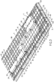
- the figure 4 illustrates in detail the secondary insulating panels 2, 2a, 2b, 2c, 2d, 2e at the level of the singular zone crossed by the sealed pipe 42.
- the other secondary insulating panels 2a, 2b, 2d, 2e of the singular row 50 only comprise metal plates 17 extending in the longitudinal direction of said panels 2a, 2b, 2d, 2e since the edges of the longitudinal ends of each metal sheets of the secondary waterproofing membrane which cover the single row 50 protrude on either side of the longitudinal ends of the panels 2a, 2b, 2d, 2 e and are welded to the metal plates 18 of the secondary insulating panels 2 bordering the singular row 50.
- the secondary insulating panel 2c crossed by the sealed pipe 42 has on either side of the sealed pipe 42 metal plates 51 extending in the transverse direction of said panel 2c. These metal plates 51 are intended for anchoring a secondary closure plate equipped with an opening through which the sealed pipe passes, which will be described in more detail below.
- the studs 19 fixed to the internal plate 10 of the panels are positioned in accordance with the arrangement of the primary insulating panels 6, 6a, 6b, 6c so that each primary insulating panel 6, 6a, 6b, 6c is anchored to the at its four corners and at its side edges on the secondary insulating panels 2, 2a, 2b, 2c, 2d, 2e.
- the figure 5 illustrates in detail the secondary waterproofing membrane 4 in the singular area.
- the secondary sealing membrane 4 comprises a secondary closure plate 53, metallic, of square shape.
- the secondary closure plate 53 has a central circular opening 54 through which passes the sealed pipe, not shown in the figure. figure 5 .
- the secondary closure plate 53 is welded to the aforementioned metal plates 51 which are fixed to the secondary insulating panel 2c.
- the two corrugated metal plates 24a, 24b arranged on either side of the sealed pipe 42 are cut to provide a window having dimensions slightly smaller than that of the secondary closure plate 53.
- the two corrugated metal plates 24a , 24b are sealed overlap welded to the secondary closure plate 53.
- the secondary closure plate 53 has dimensions such that each of its sides meets a series of three corrugations 25a, 25b, 25c, 26a, 26b, 26c.
- the sealed pipe 42 is centered on a position corresponding to the intersection between the guidelines of the central corrugations 25b, 26b of each of these series.
- the guidelines of the central corrugations 25b, 26b are therefore interrupted at the level of the secondary closure plate 53.
- the central corrugations 25b, 26b are closed in a sealed manner with end pieces 55.
- Each end piece 55 has a sole in two. parts sealed to the secondary closure plate 53 and a shell sealed to the central corrugation 25b, 26b at its interruption.
- the secondary closure plate 53 has two pairs of parallel corrugations 56a, 56b, 57a, 57b. Each of the pairs 56a, 56b, 57a, 57b has corrugations perpendicular to those of the other pair.
- the two corrugations 56a and 56b or 57a and 57b of the same pair pass on either side of the circular opening 54 and extend in the extension of the two lateral corrugations 25a, 25c, 26a, 26c of one of the series meeting the secondary closure plate 53.
- the continuity of part of the corrugations 25a,, 25c, 26a,, 26c, meeting the secondary closure plate 53 is ensured, which makes it possible to limit losses elasticity of the secondary waterproofing membrane 4 at the level of the singular zone.
- corrugations 56a, 56b, 57a, 57b of the secondary closure plate 53 protrude outwards from the tank, that is to say in the direction of the supporting structure and are housed inside grooves 14, 15 formed in the internal plate of the secondary insulating panel 2c.
- the secondary closure plate 53 is also equipped with cutouts 58 allowing the passage of studs, not shown on the figure. figure 5 , intended to ensure the fixing of the primary insulating panels 6a, 6b, 6c of the primary thermally insulating barrier.
- the figure 6 illustrates in detail the arrangement of the primary thermally insulating barrier 5 in the singular area of the ceiling wall.
- one of the primary insulating panels 6b of the series of three remarkable panels 6a, 6b, 6c, the orientation of which is perpendicular to that of the other primary insulating panels 6, passes through the sealed pipe 42.
- a closure plate primary 59 of the primary waterproofing membrane 7 is fixed to said primary insulating panel 6b.
- Primary closure plate 59 is provided with an opening for the passage of the sealed pipe 42.
- the sealed pipe 42 is sealed to the primary closure plate 59.
- the three primary insulating panels 6a, 6b, 6c in fact have arrangements of metal plates 60, 61, 62, 63, 64 which are arranged so that they are adapted to the anchoring of the edges of metal sheets of the membrane.
- primary sealing 7 which are arranged in the singular zone, and which have particular dimensions.
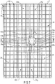
- the arrangement of the primary waterproofing membrane 7, in the singular zone of the ceiling wall, is shown in figure 7 .
- Only seven corrugated metal sheets 39a, 39b, 39c, 39d, 39e, 39f, 39g have different dimensions from those of standard corrugated metal sheets 39 covering the standard area of the vessel wall.
- This particular arrangement aims to prevent the cutting of a window in the primary waterproofing membrane 7 to allow the passage of the sealed pipe 42 is made at a corner zone of the corrugated metal sheets 39, which would have the effect of affecting their mechanical strength.
- the two corrugated metal sheets 39a, 39b arranged on either side of the sealed pipe 42 have smaller dimensions than those of the standard corrugated metal sheets 39. Thus, these two corrugated metal sheets 39a, 39b have only two large corrugations for six small corrugations.
- the two corrugated metal sheets 39a, 39b each have a cutout formed along one of their longitudinal edges and centered along the longitudinal dimension of said corrugated metal sheet 39a, 39b. The cutouts together form a window having dimensions slightly smaller than those of the primary closure plate 52.
- the two corrugated metal sheets 39a, 39b are overlapped welded around the entire periphery of the primary closure plate 52.
- the primary closure plate 52 has dimensions such that each of its sides meets a series of two corrugations 40a, 40b, 41a, 41b.
- the sealed pipe 42 is centered on a position corresponding to the intersection between two perpendicular lines d 1 , d 2 , one of which (d 1 ) is parallel to the two corrugations 40a, 40b of one of the series and disposed at an equal distance between these two corrugations 40a, 40b and the other of which (d 2 ) is parallel to the two corrugations 41a, 41b of the other of the series and disposed at an equal distance between them.
- the corrugations 40a, 40b, 41a, 41b meeting the primary closure plate 52 are sealed with end pieces 65.
- the end pieces 65 each have a two-part sole sealed to the primary closure plate 52 and a shell welded in a corrugation-tight manner at its interruption.
- the primary waterproofing membrane comprises five other corrugated sheets compensation 39c, 39d, 39e, 39f, 39g, the dimensions of which are adjusted such that the arrangement of the set of the two sheets 39a, 39b bordering the sealed pipe 45 and the five corrugated sheets 39c, 39d, 39e, 39f , 39g are equivalent to the arrangement of four corrugated metal sheets of standard dimensions.
- the compensation sheet 39c has two high corrugations 40 for six low corrugations 39 while the other four compensation plates 39d, 39e, 39f, 39g each have three high corrugations 40 for six low undulations 39.
- the corrugated metal sheets 24 of the secondary waterproofing membrane 4 have corrugations 66 projecting towards the interior of the tank, unlike the corrugations of the previous embodiment.
- the corrugated metal sheets 24 of the secondary waterproofing membrane 4 also have two series of perpendicular corrugations 66.
- the corrugated metal sheets 24 are fixed to the inner plate 10 of the insulation panels 2 of the barrier. thermally insulating secondary 1 by means of metal plates, not shown, extending in two perpendicular directions which are fixed to the internal plate 10 of the insulating panels 2.
- the outer plate 30 of the insulating panels 6 of the primary thermally insulating barrier 5 have two series of grooves 67 perpendicular to each other so as to form a network of grooves.
- the grooves 67 are thus intended to receive the corrugations 66, projecting towards the interior of the tank, formed on the corrugated metal sheets 24 of the secondary waterproofing membrane 4.
- the secondary waterproofing membrane comprises a general structure identical to that shown in FIG. figure 5 , the only difference residing in the orientation of the corrugations 66 towards the interior of the tank.
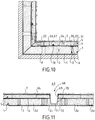
- a sealed and thermally insulating tank wall structure as described above could also be produced at any other type of through element, and in particular at a sump structure 68, as illustrated. on the figure 11 , passing through the bottom wall and intended to accommodate a suction member, for example a pump, not shown.
- the sump structure 68 comprises a conical or primary cylindrical bowl 69, the axis of which is perpendicular to the supporting wall 3.
- the primary cylindrical bowl 69 is continuously connected to the primary sealing membrane 7 which it thus completes with waterproof way.
- the sump structure further comprises a secondary conical or cylindrical bowl 70, concentric with the primary bowl 69, which is connected continuously to the secondary waterproofing membrane 4 which it thus completes in a sealed manner.
- the sump structure 68 also includes insulating materials 71 which are housed between the primary and secondary cylindrical bowls 69, 70 as well as insulating materials 72 interposed between the secondary bowl 70 and the supporting structure 3 in order to ensure continuity. thermal insulation of the primary and secondary thermally insulating barriers 1, 5 at the level of the sump structure 68.
- the tank described above can be used in various types of installation, in particular in an onshore installation or in a floating structure such as an LNG vessel or the like.
- a cut-away view of an LNG carrier 70 shows such a sealed and insulated tank 71 of generally prismatic shape mounted in the double hull 72 of the ship.
- loading / unloading pipes 73 arranged on the upper deck of the ship can be connected, by means of suitable connectors, to a maritime or port terminal for transferring a cargo of LNG from or to the tank 71.
- the figure 9 also represents an example of a maritime terminal comprising a loading and unloading station 75, an underwater pipe 76 and an onshore installation 77.
- the loading and unloading station 75 is a fixed off-shore installation comprising a mobile arm 74 and a tower 78 which supports the movable arm 74.
- the movable arm 74 carries a bundle of insulated flexible pipes 79 which can be connected to the loading / unloading pipes 73.
- the movable arm 74 can be swiveled and adapts to all sizes of LNG carriers.
- a connecting pipe, not shown, extends inside the tower 78.
- the loading and unloading station 75 allows the loading and unloading of the LNG carrier 70 from or to the onshore installation 77.
- the latter comprises liquefied gas storage tanks 80 and connecting pipes 81 connected by the underwater pipe 76 to the loading or unloading station 75.
- the underwater pipe 76 allows the transfer of the liquefied gas between the loading or unloading station 75 and the shore installation 77 over a great distance, for example 5 km, which makes it possible to keep the LNG carrier 70 at a great distance from the coast during loading and unloading operations.
- pumps on board the ship 70 and / or pumps fitted to the shore installation 77 and / or pumps fitted to the loading and unloading station 75 are used.
Landscapes
- Engineering & Computer Science (AREA)
- Mechanical Engineering (AREA)
- General Engineering & Computer Science (AREA)
- Physics & Mathematics (AREA)
- Thermal Sciences (AREA)
- Chemical & Material Sciences (AREA)
- Combustion & Propulsion (AREA)
- Ocean & Marine Engineering (AREA)
- Filling Or Discharging Of Gas Storage Vessels (AREA)
Claims (25)
- Dichter und thermisch isolierender Tank, der zum Speichern eines Fluids bestimmt ist, wobei der Tank eine an einem Tragwerk (3) befestigte Tankwand aufweist, wobei die Wand nacheinander in Richtung der Dicke von der Außen- zur Innenseite des Tanks eine sekundäre thermisch isolierende Sperre (1), die gegen das Tragwerk (3) gehalten wird, eine von der sekundären thermisch isolierenden Sperre (1) getragene sekundäre Dichtungsmembran (4), eine primäre thermisch isolierende Sperre (5), die gegen die sekundäre Dichtungsmembran (4) anliegt, und eine primäre Dichtungsmembran (7) aufweist, die von der primären thermisch isolierenden Sperre (5) getragen wird und dazu bestimmt ist, mit dem im Tank enthaltenen Fluid in Kontakt zu sein;
wobei die sekundäre thermisch isolierende Sperre (1) nebeneinander liegende sekundäre Isolierplatten (2, 2a, 2b, 2c, 2d, 2e) aufweist, die gegen das Tragwerk (3) gehalten werden und eine rechtwinklige parallelepipedische Form mit einer Längsrichtung aufweisen, wobei jede sekundäre Isolierplatte (2, 2a, 2b, 2c, 2d, 2e) eine der Tragwand gegenüberliegende Innenseite aufweist, die mit mindestens einem Verankerungsorgan (19) ausgestattet ist;
wobei die primäre thermisch isolierende Sperre (5) nebeneinander liegende primäre Isolierplatten (6, 6a, 6b, 6c) aufweist, die eine rechtwinklige parallelepipedische Form mit einer Längsrichtung aufweisen, wobei der dichte Tank mit einem Durchgangselement (42, 68) ausgestattet ist, das durch einen besonderen Bereich der Wand geht; wobei die primäre thermisch isolierende Sperre (5) im besonderen Bereich der Tankwand eine primäre Serie von primären Isolierplatten (6a, 6b, 6c) enthält, die zueinander parallele Längsrichtungen aufweisen;
wobei die sekundäre thermisch isolierende Sperre (1) im besonderen Bereich der Wand eine sekundäre Serie von sekundären Isolierplatten (2a, 2b, 2c, 2d, 2e) aufweist, die zueinander parallele Längsrichtungen aufweisen; wobei das Durchgangselement (42, 68) sich in Richtung der Dicke des besonderen Bereichs der Wand erstreckt und nacheinander durch eine Öffnung, die in einer der sekundären Isolierplatten (2c) der sekundären Serie eingerichtet ist, und durch eine Öffnung (54) geht, die in der sekundären Dichtungsmembran (4) eingerichtet ist, wobei der Tank dadurch gekennzeichnet ist, dass jede primäre Isolierplatte (6, 6a, 6b, 6c) überlappend auf mindestens vier sekundären Isolierplatten (2, 2a, 2b, 2c, 2d, 2e) angeordnet und am Verankerungsorgan (19) jeder der sekundären Isolierplatten verankert ist, die die primäre Isolierplatte überlappt; dass die primäre Serie und die sekundäre Serie so zueinander angeordnet sind, dass die Längsrichtungen der primären Isolierplatten (6a, 6b, 6c) der primären Serie lotrecht zu den Längsrichtungen der sekundären Isolierplatten (2a, 2b, 2c, 2d, 2e) der sekundären Serie sind; und dass das Durchgangselement (42, 68) sich außerdem durch eine in einer der primären Isolierplatten (6b) der primären Serie eingerichtete Öffnung und durch eine in der primären Dichtungsmembran (7) eingerichtete Öffnung erstreckt. - Tank nach Anspruch 1, wobei die in einem um den besonderen Bereich der Wand herum befindlichen verbleibenden Bereich angeordneten sekundären Isolierplatten (2) in parallelen Reihen eingerichtet sind und parallel zueinander ausgerichtete Längsrichtungen aufweisen, und die im verbleibenden Bereich angeordneten primären Isolierplatten (6) in parallelen Reihen eingerichtet sind und parallel zueinander ausgerichtete Längsrichtungen aufweisen.
- Tank nach Anspruch 2, wobei die Längsrichtungen der sekundären Isolierplatten (2) des verbleibenden Bereichs parallel zu den Längsrichtungen der primären Isolierplatten (6) des verbleibenden Bereichs sind, und wobei die Längsrichtungen der Isolierplatten (6a, 6b, 6c) einer der primären und sekundären Serien lotrecht zu den Längsrichtungen der primären und sekundären Isolierplatten (2, 6) des verbleibenden Bereichs ausgerichtet sind, und die Längsrichtungen der Isolierplatten (2a, 2b, 2c, 2d, 2e) der anderen der primären und sekundären Serien parallel zu den Längsrichtungen der primären und sekundären Isolierplatten (2, 6) des verbleibenden Bereichs ausgerichtet sind.
- Tank nach Anspruch 3, wobei die Serie, deren Isolierplatten (6a, 6b, 6c) lotrecht zu den Längsrichtungen der primären und sekundären Isolierplatten (2, 6) des verbleibenden Bereichs ausgerichtete Längsrichtungen aufweisen, die primäre Serie ist.
- Tank nach Anspruch 4, wobei die primären Isolierplatten (6) des verbleibenden Bereichs gleiche Abmessungen wie diejenigen der primären Isolierplatten (6a, 6b, 6c) der primären Serie aufweisen.
- Tank nach Anspruch 5, wobei die primären Isolierplatten (6, 6a, 6b, 6c) je eine Längsabmessung gleich n Mal ihre Querabmessung aufweisen, wobei n eine ganze Zahl größer als 1 ist, und wobei die primäre Serie n primäre Isolierplatten (6a, 6b, 6c) aufweist.
- Tank nach einem der Ansprüche 2 bis 6, wobei die sekundären Isolierplatten (2) des verbleibenden Bereichs Längs- und Querabmessungen gleich denjenigen der primären Isolierplatten (6) des verbleibenden Bereichs aufweisen.
- Tank nach einem der Ansprüche 2 bis 7, wobei die sekundäre Serie von sekundären Isolierplatten (2a, 2b, 2c, 2d, 2e) eine Reihe von sekundären Isolierplatten aufweist, die sich von einem Rand der Tankwand zum anderen gemäß einer Querrichtung lotrecht zur Längsrichtung der sekundären Isolierplatten erstreckt, und wobei die sekundären Isolierplatten (2a, 2b, 2c, 2d, 2e) der sekundären Serie eine Längsabmessung kleiner als die Längsabmessung der sekundären Isolierplatten (2) im verbleibenden Bereich aufweisen.
- Tank nach einem der Ansprüche 1 bis 8, wobei die Öffnung, durch die hindurch das Durchgangselement (42, 68) geht, die in der sekundären Isolierplatte (2c) der sekundären Serie eingerichtet ist, in der Mitte der sekundären Isolierplatte (2c) angeordnet ist.
- Tank nach einem der Ansprüche 1 bis 9, wobei die Öffnung, durch die das Durchgangselement (42, 68) geht, die in der primären Isolierplatte (6b) der primären Serie eingerichtet ist, auf die Mitte der Querabmessung der primären Isolierplatte (6b) zentriert ist.
- Tank nach einem der Ansprüche 1 bis 10, wobei jede sekundäre Isolierplatte (2, 2a, 2b, 2c, 2d, 2e) den benachbarten sekundären Isolierplatten mittels einer Vielzahl von Überbrückungselementen (22) zugeordnet ist, wobei jedes Überbrückungselement (22) überlappend zwischen mindestens der sekundären Isolierplatte und einer benachbarten sekundären Isolierplatte angeordnet ist und einerseits an einem Rand der Innenseite einer der sekundären Isolierplatten und andererseits an einem gegenüberliegenden Rand der Innenseite der anderen sekundären Isolierplatte befestigt ist, um einem Entfernen der benachbarten sekundären Isolierplatten voneinander entgegenzuwirken.
- Tank nach einem der Ansprüche 1 bis 11, wobei die Innenseite jeder sekundären Isolierplatte (2, 2a, 2b, 2c, 2d, 2e) mit Metallplatinen (17, 18, 51) ausgestattet ist, wobei die sekundäre Dichtungsmembran (4) im besonderen Bereich der Wand eine sekundäre Verschlussplatte (53) aufweist, die mit der Öffnung (54) ausgestattet ist, durch die das Durchgangselement (42, 68) geht; wobei die sekundäre Verschlussplatte (53) auf die Metallplatinen (51) der mit der Öffnung ausgestatteten sekundären Isolierplatte (2c) geschweißt ist.
- Tank nach Anspruch 12, wobei die sekundäre Dichtungsmembran (4) eine Vielzahl von sekundären Wellblechen (24, 24a, 24b) aufweist, die dicht aneinandergeschweißt sind und je mindestens zwei lotrechte Welligkeiten (25, 26) enthalten, wobei die sekundären Bleche (24, 24a, 24b) an die Metallplatinen (17, 18, 51) der sekundären Isolierplatten (2, 2a, 2b, 2c, 2d, 2e) geschweißt sind, wobei die der sekundären Verschlussplatte (53) benachbarten sekundären Wellbleche (24a, 24b) an diese geschweißt sind.
- Tank nach Anspruch 13, wobei das Durchgangselement (42, 68) auf eine Position zentriert ist, die der Kreuzung zwischen den Leitlinien von zwei zueinander lotrechten Welligkeiten (25b, 26b) der sekundären Bleche (24a, 24b) entspricht.
- Tank nach einem der Ansprüche 12 bis 14, wobei die sekundäre Verschlussplatte (53) zwei Paare paralleler Welligkeiten (56a, 56b, 57a, 57b) aufweist, wobei die zwei Welligkeiten (56a, 56b; 57a, 57b) eines gleichen Paars zu beiden Seiten der Öffnung (54) verlaufen und sich je in der Verlängerung einer Welligkeit (25a, 25c, 26a, 26c) eines der sekundären Wellbleche (24a, 24b) erstrecken.
- Tank nach einem der Ansprüche 13 bis 15, wobei die Welligkeiten (25, 26) der sekundären Bleche (24, 24a, 24b) nach außerhalb des Tanks in Richtung des Tragwerks vorstehen, wobei die Innenseite der sekundären Isolierplatten (2, 2a, 2b, 2c, 2d, 2e) lotrechte Rillen (14, 15) aufweist, die die Welligkeiten (25, 26) der sekundären Bleche (24, 24a, 24b) aufnehmen.
- Tank nach einem der Ansprüche 13 bis 15, wobei die Welligkeiten (66) der sekundären Bleche (24) zur Innenseite des Tanks vorstehen, wobei die primären Isolierplatten (6) je eine Außenseite (31) aufweisen, die lotrechte Rillen (67) aufweist, die die Welligkeiten (66) der Wellbleche (24) der sekundären Dichtungsmembran (4) aufnehmen.
- Tank nach einem der Ansprüche 1 bis 17, wobei die primäre Dichtungsmembran (7) im besonderen Bereich der Wand eine primäre Verschlussplatte (52) aufweist, die mit der Öffnung der primären Dichtungsmembran ausgestattet ist, durch die das Durchgangselement geht; wobei die primäre Verschlussplatte (52) dicht an das Durchgangselement (52) geschweißt und an der mit der Öffnung ausgestatteten primären Isolierplatte (6b) befestigt ist.
- Dichter Tank nach Anspruch 18, wobei jede primäre Isolierplatte (6, 6a, 6b, 6c) der primären thermisch isolierenden Sperre eine Innenseite gegenüber der Tragwand aufweist; wobei die Innenseite mit Metallplatinen (32, 33, 60, 61, 62, 63) ausgestattet ist, wobei die primäre Dichtungsmembran (7) eine Vielzahl von primären Wellblechen (39, 39a, 39b, 39c, 39d, 39e, 39f, 39g) aufweist, die dicht aneinander geschweißt sind und je mindestens zwei lotrechte Welligkeiten (40, 41, 40a, 40b, 41a, 41b) enthalten, wobei die primären Bleche (39, 39a, 39b, 39c, 39d, 39e, 39f, 39g) auf die Metallplatinen der primären Isolierplatten (6, 6a, 6b, 6c) geschweißt sind, wobei die der primären Verschlussplatte (52) benachbarten primären Wellbleche (39a, 39b) an diese geschweißt sind.
- Dichter Tank nach Anspruch 19, wobei das Durchgangselement (42, 68) auf eine Position entsprechend der Kreuzung zwischen einer ersten und einer zweiten Geraden (d1, d2) zentriert ist, wobei die erste Gerade (d1) parallel zu einem ersten Paar von parallelen Welligkeiten (40a, 40b) der primären Dichtungsmembran (7) und in gleichem Abstand zwischen den Welligkeiten (40a, 40b) des ersten Paars angeordnet ist, und die zweite Gerade (d2) parallel zu einem zweiten Paar von parallelen Welligkeiten (41a, 41b) ist, die lotrecht zu den Welligkeiten (40a, 40b) des ersten Paars sind, und in gleichem Abstand zwischen den Welligkeiten (41a, 41b) des zweiten Paars angeordnet ist.
- Dichter Tank nach einem der Ansprüche 1 bis 20, wobei das Durchgangselement (42) eine dichte Leitung ist, die durch einen besonderen Bereich der Wand hindurchgeht, um einen Durchgang zwischen dem Innenraum des Tanks und der Außenseite des Tanks zu definieren.
- Dichter Tank nach einem der Ansprüche 1 bis 20, wobei das Durchgangselement (68) eine Sumpfstruktur ist.
- Schiff (70) für den Transport eines Fluids, wobei das Schiff einen Doppelrumpf (72) und einen Tank (71) nach einem der Ansprüche 1 bis 22 aufweist, der in dem Doppelrumpf angeordnet ist.
- Verfahren zum Be- oder Entladen eines Schiffs (70) nach Anspruch 23, wobei ein Fluid durch isolierte Rohrleitungen (73, 79, 76, 81) von oder zu einer schwimmenden oder an Land befindlichen Anlage (77) zu oder vom Tank des Schiffs (71) befördert wird.
- Transfersystem für ein Fluid, wobei das System ein Schiff (70) nach Anspruch 23, isolierte Rohrleitungen (73, 79, 76, 81), die so eingerichtet sind, dass sie den im Rumpf des Schiffs eingebauten Tank (71) mit einer schwimmenden oder an Land befindlichen Speichereinrichtung (77) verbinden, und eine Pumpe aufweist, um ein Fluid durch die isolierten Rohrleitungen hindurch von oder zu der im Wasser oder an Land befindlichen Speicheranlage zu oder von einem Tank des Schiffs anzutreiben.
Applications Claiming Priority (2)
| Application Number | Priority Date | Filing Date | Title |
|---|---|---|---|
| FR1553349A FR3035174B1 (fr) | 2015-04-15 | 2015-04-15 | Cuve equipee d'une paroi presentant une zone singuliere au travers de laquelle passe un element traversant |
| PCT/FR2016/050866 WO2016166481A2 (fr) | 2015-04-15 | 2016-04-14 | Cuve équipée d'une paroi présentant une zone singulière au travers de laquelle passe un élément traversant |
Publications (2)
| Publication Number | Publication Date |
|---|---|
| EP3283813A2 EP3283813A2 (de) | 2018-02-21 |
| EP3283813B1 true EP3283813B1 (de) | 2021-02-17 |
Family
ID=53514350
Family Applications (1)
| Application Number | Title | Priority Date | Filing Date |
|---|---|---|---|
| EP16733131.3A Active EP3283813B1 (de) | 2015-04-15 | 2016-04-14 | Tank mit einer wand mit einer spezifischen zone für den durchgang eines durchgangselements |
Country Status (12)
| Country | Link |
|---|---|
| US (1) | US10203066B2 (de) |
| EP (1) | EP3283813B1 (de) |
| JP (1) | JP6640244B2 (de) |
| KR (1) | KR102497296B1 (de) |
| CN (1) | CN107667244B (de) |
| AU (1) | AU2016250122B2 (de) |
| FR (1) | FR3035174B1 (de) |
| MY (1) | MY187825A (de) |
| PH (1) | PH12017501868B1 (de) |
| RU (1) | RU2697074C2 (de) |
| SG (1) | SG11201708382YA (de) |
| WO (1) | WO2016166481A2 (de) |
Families Citing this family (14)
| Publication number | Priority date | Publication date | Assignee | Title |
|---|---|---|---|---|
| FR3035175B1 (fr) * | 2015-04-20 | 2017-04-28 | Gaztransport Et Technigaz | Cuve etanche et thermiquement isolante equipee d'un element traversant |
| US10378695B2 (en) * | 2016-05-25 | 2019-08-13 | Savsu Technologies Llc | Cryogenic storage container |
| FR3069904B1 (fr) | 2017-08-07 | 2020-10-02 | Gaztransport Et Technigaz | Cuve etanche et thermiquement isolante comportant une structure de dome gaz |
| FR3070745B1 (fr) * | 2017-09-04 | 2019-09-06 | Gaztransport Et Technigaz | Cuve etanche et thermiquement isolante a element de remplissage anti-convectif |
| WO2019077253A1 (fr) * | 2017-10-20 | 2019-04-25 | Gaztransport Et Technigaz | Cuve etanche et thermiquement isolante a plusieurs zones |
| FR3072758B1 (fr) * | 2017-10-20 | 2019-11-01 | Gaztransport Et Technigaz | Cuve etanche et thermiquement isolante a plusieurs zones |
| WO2019099803A1 (en) | 2017-11-17 | 2019-05-23 | Savsu Technologies, Inc. | Dry vapor cryogenic container with absorbent core |
| FR3077116B1 (fr) * | 2018-01-23 | 2021-01-08 | Gaztransport Et Technigaz | Cuve etanche et thermiquement isolante |
| FR3077115B1 (fr) * | 2018-01-23 | 2021-02-12 | Gaztransport Et Technigaz | Cuve etanche et thermiquement isolante. |
| FR3082595B1 (fr) * | 2018-06-13 | 2020-06-19 | Gaztransport Et Technigaz | Cuve etanche et thermiquement isolante |
| FR3108383B1 (fr) * | 2020-03-20 | 2023-10-27 | Gaztransport Et Technigaz | Cuve étanche et thermiquement isolante |
| FR3109979B1 (fr) * | 2020-05-05 | 2022-04-08 | Gaztransport Et Technigaz | Cuve étanche et thermiquement isolante comprenant des éléments de remplissage anti-convectif |
| FR3112588B1 (fr) * | 2020-07-20 | 2022-07-22 | Gaztransport Et Technigaz | Paroi d'une cuve de stockage d'un gaz liquéfiée |
| FR3117993A1 (fr) * | 2020-12-22 | 2022-06-24 | Gaztransport Et Technigaz | Navire comprenant une cuve |
Family Cites Families (23)
| Publication number | Priority date | Publication date | Assignee | Title |
|---|---|---|---|---|
| SU932091A1 (ru) * | 1980-01-09 | 1982-05-30 | Предприятие П/Я А-7937 | Теплова изол ци корпуса высокого давлени |
| CN85105351B (zh) * | 1985-07-13 | 1988-04-13 | 日本钢管株式会社 | 液化气储运罐的绝热方法和系统 |
| JP2582984Y2 (ja) * | 1991-07-12 | 1998-10-15 | 川崎重工業株式会社 | 低温貯槽のメンブレンのノズル等貫通部構造 |
| JPH08219399A (ja) * | 1995-02-08 | 1996-08-30 | Ishikawajima Harima Heavy Ind Co Ltd | 低温液化ガス貯蔵タンクにおける屋根のノズル貫通装置 |
| JP3978892B2 (ja) * | 1998-09-28 | 2007-09-19 | 株式会社Ihi | タンク用ポンプピットおよびその施工方法 |
| FR2798902B1 (fr) * | 1999-09-29 | 2001-11-23 | Gaz Transport & Technigaz | Cuve etanche et thermiquement isolante integree dans une structure porteuse de navire et procede de fabrication de caissons isolants destines a etre utilises dans cette cuve |
| JP2001108198A (ja) * | 1999-10-04 | 2001-04-20 | Kawasaki Heavy Ind Ltd | Lngなどの低温地下式貯槽 |
| FR2826630B1 (fr) * | 2001-06-29 | 2003-10-24 | Gaz Transport & Technigaz | Cuve etanche et thermiquement isolante avec aretes longitudinales obliques |
| WO2008007837A1 (en) * | 2006-07-11 | 2008-01-17 | Hyundai Heavy Industries Co., Ltd. | Seam butt type insulation system having weldable secondary barrier for lng tanks |
| CN101688640B (zh) * | 2007-05-29 | 2011-06-08 | 现代重工业株式会社 | 具有焊接的次防壁的液化天然气储存箱绝热系统及其构造方法 |
| KR101122292B1 (ko) * | 2008-06-19 | 2012-03-21 | 삼성중공업 주식회사 | 액화천연가스 운반선 화물창의 단열구조 및 그것의 시공방법 |
| FR2961580B1 (fr) * | 2010-06-17 | 2012-07-13 | Gaztransport Et Technigaz | Cuve etanche et isolante comportant un pied de support |
| FR2977575B1 (fr) * | 2011-07-06 | 2014-06-27 | Gaztransp Et Technigaz | Coupleur pour maintenir un element par rapport a une structure de retenue |
| FR2977562B1 (fr) * | 2011-07-06 | 2016-12-23 | Gaztransport Et Technigaz | Cuve etanche et thermiquement isolante integree dans une structure porteuse |
| RU2522691C2 (ru) * | 2012-05-31 | 2014-07-20 | Российская Федерация, от имени которой выступает Министерство промышленности и торговли Российской Федерации (Минпромторг России) | Мембранная грузовая емкость для транспортировки и хранения сжиженного природного газа |
| FR2991748B1 (fr) * | 2012-06-11 | 2015-02-20 | Gaztransp Et Technigaz | Cuve etanche et thermiquement isolante |
| FR2996520B1 (fr) * | 2012-10-09 | 2014-10-24 | Gaztransp Et Technigaz | Cuve etanche et thermiquement isolante comportant une membrane metalique ondulee selon des plis orthogonaux |
| FR3001945B1 (fr) | 2013-02-14 | 2017-04-28 | Gaztransport Et Technigaz | Paroi etanche et thermiquement isolante pour cuve de stockage de fluide |
| FR3002515B1 (fr) * | 2013-02-22 | 2016-10-21 | Gaztransport Et Technigaz | Paroi de cuve comportant un element traversant |
| KR101919167B1 (ko) * | 2013-04-05 | 2018-11-16 | 현대중공업 주식회사 | 극저온 물질 운반선의 화물창 |
| RU2558907C1 (ru) * | 2014-03-20 | 2015-08-10 | Открытое акционерное общество "Акционерная компания по транспорту нефти "Транснефть" (ОАО "АК "Транснефть") | Теплоизолированный резервуар |
| EP3165441A4 (de) * | 2014-07-04 | 2018-06-27 | Daewoo Shipbuilding & Marine Engineering Co., Ltd. | Flüssigerdgasspeichertank und isolierwand für den flüssigerdgasspeichertank |
| FR3026459B1 (fr) * | 2014-09-26 | 2017-06-09 | Gaztransport Et Technigaz | Cuve etanche et isolante comportant un element de pontage entre les panneaux de la barriere isolante secondaire |
-
2015
- 2015-04-15 FR FR1553349A patent/FR3035174B1/fr not_active Expired - Fee Related
-
2016
- 2016-04-14 US US15/565,819 patent/US10203066B2/en not_active Expired - Fee Related
- 2016-04-14 JP JP2017553960A patent/JP6640244B2/ja active Active
- 2016-04-14 SG SG11201708382YA patent/SG11201708382YA/en unknown
- 2016-04-14 MY MYPI2017703855A patent/MY187825A/en unknown
- 2016-04-14 RU RU2017136171A patent/RU2697074C2/ru active
- 2016-04-14 AU AU2016250122A patent/AU2016250122B2/en not_active Ceased
- 2016-04-14 EP EP16733131.3A patent/EP3283813B1/de active Active
- 2016-04-14 WO PCT/FR2016/050866 patent/WO2016166481A2/fr active Application Filing
- 2016-04-14 KR KR1020177032539A patent/KR102497296B1/ko active IP Right Grant
- 2016-04-14 CN CN201680028820.9A patent/CN107667244B/zh active Active
-
2017
- 2017-10-11 PH PH12017501868A patent/PH12017501868B1/en unknown
Non-Patent Citations (1)
| Title |
|---|
| None * |
Also Published As
| Publication number | Publication date |
|---|---|
| RU2697074C2 (ru) | 2019-08-12 |
| JP2018512344A (ja) | 2018-05-17 |
| CN107667244B (zh) | 2020-01-03 |
| KR20170137158A (ko) | 2017-12-12 |
| PH12017501868A1 (en) | 2018-02-26 |
| RU2017136171A3 (de) | 2019-06-11 |
| US20180112823A1 (en) | 2018-04-26 |
| EP3283813A2 (de) | 2018-02-21 |
| FR3035174A1 (fr) | 2016-10-21 |
| SG11201708382YA (en) | 2017-11-29 |
| JP6640244B2 (ja) | 2020-02-05 |
| WO2016166481A2 (fr) | 2016-10-20 |
| WO2016166481A3 (fr) | 2016-12-08 |
| FR3035174B1 (fr) | 2017-04-28 |
| AU2016250122A1 (en) | 2017-11-02 |
| AU2016250122B2 (en) | 2019-02-14 |
| CN107667244A (zh) | 2018-02-06 |
| PH12017501868B1 (en) | 2018-02-26 |
| RU2017136171A (ru) | 2019-05-15 |
| MY187825A (en) | 2021-10-26 |
| US10203066B2 (en) | 2019-02-12 |
| KR102497296B1 (ko) | 2023-02-07 |
Similar Documents
| Publication | Publication Date | Title |
|---|---|---|
| EP3283813B1 (de) | Tank mit einer wand mit einer spezifischen zone für den durchgang eines durchgangselements | |
| EP3320256B1 (de) | Abgedichteter und wärmeisolierter tank mit sekundärdichtungsmembran mit einer eckanordnung mit wellblechen | |
| EP3198186B1 (de) | Abgedichtetes und isoliertes gefäss mit einem überbrückungselement zwischen den platten der sekundären isolierbarriere | |
| EP3286489B1 (de) | Abgedichteter und thermisch isolierter tank mit einem durchgangselement | |
| EP2984384B1 (de) | Winkelkonstruktion eines versiegelten und wärmeisolierenden tanks zum speichern eines fluids | |
| FR3058498B1 (fr) | Structure d'angle d'une cuve etanche et thermiquement isolante et son procede d'assemblage | |
| WO2017064426A1 (fr) | Cuve étanche et thermiquement isolante | |
| EP3365592B1 (de) | Behälter mit isolierenden eckblöcken, die mit belastungslindernden schlitzen versehen sind | |
| WO2014125186A1 (fr) | Paroi, etanche et thermiquement isolante, pour cuve de stockage de fluide | |
| FR3004510A1 (fr) | Cuve etanche et thermiquement isolante de stockage d'un fluide | |
| EP3114387B1 (de) | Abgedichteter und isolierter kessel mit ablenkelement zur ermöglichung des gasstroms an einer ecke | |
| WO2020039134A1 (fr) | Paroi de cuve étanche et thermiquement isolante | |
| WO2019239048A1 (fr) | Cuve etanche et thermiquement isolante | |
| EP3942219B1 (de) | Wärmeisolierender abgedichteter tank | |
| FR3064042A1 (fr) | Cuve etanche et thermiquement isolante comportant un bouchon isolant de renfort | |
| WO2021058824A1 (fr) | Cuve étanche et thermiquement isolante | |
| WO2020115406A1 (fr) | Cuve etanche et thermiquement isolante | |
| EP3665414A1 (de) | Abgedichteter und wärmeisolierender tank | |
| WO2022074226A1 (fr) | Cuve étanche et thermiquement isolante | |
| WO2023025501A1 (fr) | Installation de stockage pour gaz liquéfié |
Legal Events
| Date | Code | Title | Description |
|---|---|---|---|
| STAA | Information on the status of an ep patent application or granted ep patent |
Free format text: STATUS: THE INTERNATIONAL PUBLICATION HAS BEEN MADE |
|
| PUAI | Public reference made under article 153(3) epc to a published international application that has entered the european phase |
Free format text: ORIGINAL CODE: 0009012 |
|
| STAA | Information on the status of an ep patent application or granted ep patent |
Free format text: STATUS: REQUEST FOR EXAMINATION WAS MADE |
|
| 17P | Request for examination filed |
Effective date: 20171009 |
|
| AK | Designated contracting states |
Kind code of ref document: A2 Designated state(s): AL AT BE BG CH CY CZ DE DK EE ES FI FR GB GR HR HU IE IS IT LI LT LU LV MC MK MT NL NO PL PT RO RS SE SI SK SM TR |
|
| AX | Request for extension of the european patent |
Extension state: BA ME |
|
| RAP1 | Party data changed (applicant data changed or rights of an application transferred) |
Owner name: GAZTRANSPORT ET TECHNIGAZ |
|
| DAV | Request for validation of the european patent (deleted) | ||
| DAX | Request for extension of the european patent (deleted) | ||
| GRAP | Despatch of communication of intention to grant a patent |
Free format text: ORIGINAL CODE: EPIDOSNIGR1 |
|
| STAA | Information on the status of an ep patent application or granted ep patent |
Free format text: STATUS: GRANT OF PATENT IS INTENDED |
|
| INTG | Intention to grant announced |
Effective date: 20201029 |
|
| GRAS | Grant fee paid |
Free format text: ORIGINAL CODE: EPIDOSNIGR3 |
|
| GRAA | (expected) grant |
Free format text: ORIGINAL CODE: 0009210 |
|
| STAA | Information on the status of an ep patent application or granted ep patent |
Free format text: STATUS: THE PATENT HAS BEEN GRANTED |
|
| AK | Designated contracting states |
Kind code of ref document: B1 Designated state(s): AL AT BE BG CH CY CZ DE DK EE ES FI FR GB GR HR HU IE IS IT LI LT LU LV MC MK MT NL NO PL PT RO RS SE SI SK SM TR |
|
| REG | Reference to a national code |
Ref country code: GB Ref legal event code: FG4D Free format text: NOT ENGLISH |
|
| REG | Reference to a national code |
Ref country code: CH Ref legal event code: EP |
|
| REG | Reference to a national code |
Ref country code: DE Ref legal event code: R096 Ref document number: 602016052561 Country of ref document: DE |
|
| REG | Reference to a national code |
Ref country code: AT Ref legal event code: REF Ref document number: 1361928 Country of ref document: AT Kind code of ref document: T Effective date: 20210315 |
|
| REG | Reference to a national code |
Ref country code: IE Ref legal event code: FG4D Free format text: LANGUAGE OF EP DOCUMENT: FRENCH |
|
| REG | Reference to a national code |
Ref country code: LT Ref legal event code: MG9D |
|
| REG | Reference to a national code |
Ref country code: NL Ref legal event code: MP Effective date: 20210217 |
|
| PG25 | Lapsed in a contracting state [announced via postgrant information from national office to epo] |
Ref country code: BG Free format text: LAPSE BECAUSE OF FAILURE TO SUBMIT A TRANSLATION OF THE DESCRIPTION OR TO PAY THE FEE WITHIN THE PRESCRIBED TIME-LIMIT Effective date: 20210517 Ref country code: LT Free format text: LAPSE BECAUSE OF FAILURE TO SUBMIT A TRANSLATION OF THE DESCRIPTION OR TO PAY THE FEE WITHIN THE PRESCRIBED TIME-LIMIT Effective date: 20210217 Ref country code: PT Free format text: LAPSE BECAUSE OF FAILURE TO SUBMIT A TRANSLATION OF THE DESCRIPTION OR TO PAY THE FEE WITHIN THE PRESCRIBED TIME-LIMIT Effective date: 20210617 Ref country code: NO Free format text: LAPSE BECAUSE OF FAILURE TO SUBMIT A TRANSLATION OF THE DESCRIPTION OR TO PAY THE FEE WITHIN THE PRESCRIBED TIME-LIMIT Effective date: 20210517 Ref country code: GR Free format text: LAPSE BECAUSE OF FAILURE TO SUBMIT A TRANSLATION OF THE DESCRIPTION OR TO PAY THE FEE WITHIN THE PRESCRIBED TIME-LIMIT Effective date: 20210518 Ref country code: HR Free format text: LAPSE BECAUSE OF FAILURE TO SUBMIT A TRANSLATION OF THE DESCRIPTION OR TO PAY THE FEE WITHIN THE PRESCRIBED TIME-LIMIT Effective date: 20210217 Ref country code: FI Free format text: LAPSE BECAUSE OF FAILURE TO SUBMIT A TRANSLATION OF THE DESCRIPTION OR TO PAY THE FEE WITHIN THE PRESCRIBED TIME-LIMIT Effective date: 20210217 |
|
| REG | Reference to a national code |
Ref country code: AT Ref legal event code: MK05 Ref document number: 1361928 Country of ref document: AT Kind code of ref document: T Effective date: 20210217 |
|
| PG25 | Lapsed in a contracting state [announced via postgrant information from national office to epo] |
Ref country code: NL Free format text: LAPSE BECAUSE OF FAILURE TO SUBMIT A TRANSLATION OF THE DESCRIPTION OR TO PAY THE FEE WITHIN THE PRESCRIBED TIME-LIMIT Effective date: 20210217 Ref country code: RS Free format text: LAPSE BECAUSE OF FAILURE TO SUBMIT A TRANSLATION OF THE DESCRIPTION OR TO PAY THE FEE WITHIN THE PRESCRIBED TIME-LIMIT Effective date: 20210217 Ref country code: LV Free format text: LAPSE BECAUSE OF FAILURE TO SUBMIT A TRANSLATION OF THE DESCRIPTION OR TO PAY THE FEE WITHIN THE PRESCRIBED TIME-LIMIT Effective date: 20210217 Ref country code: PL Free format text: LAPSE BECAUSE OF FAILURE TO SUBMIT A TRANSLATION OF THE DESCRIPTION OR TO PAY THE FEE WITHIN THE PRESCRIBED TIME-LIMIT Effective date: 20210217 Ref country code: SE Free format text: LAPSE BECAUSE OF FAILURE TO SUBMIT A TRANSLATION OF THE DESCRIPTION OR TO PAY THE FEE WITHIN THE PRESCRIBED TIME-LIMIT Effective date: 20210217 |
|
| PG25 | Lapsed in a contracting state [announced via postgrant information from national office to epo] |
Ref country code: IS Free format text: LAPSE BECAUSE OF FAILURE TO SUBMIT A TRANSLATION OF THE DESCRIPTION OR TO PAY THE FEE WITHIN THE PRESCRIBED TIME-LIMIT Effective date: 20210617 |
|
| PG25 | Lapsed in a contracting state [announced via postgrant information from national office to epo] |
Ref country code: AT Free format text: LAPSE BECAUSE OF FAILURE TO SUBMIT A TRANSLATION OF THE DESCRIPTION OR TO PAY THE FEE WITHIN THE PRESCRIBED TIME-LIMIT Effective date: 20210217 Ref country code: SM Free format text: LAPSE BECAUSE OF FAILURE TO SUBMIT A TRANSLATION OF THE DESCRIPTION OR TO PAY THE FEE WITHIN THE PRESCRIBED TIME-LIMIT Effective date: 20210217 Ref country code: EE Free format text: LAPSE BECAUSE OF FAILURE TO SUBMIT A TRANSLATION OF THE DESCRIPTION OR TO PAY THE FEE WITHIN THE PRESCRIBED TIME-LIMIT Effective date: 20210217 Ref country code: CZ Free format text: LAPSE BECAUSE OF FAILURE TO SUBMIT A TRANSLATION OF THE DESCRIPTION OR TO PAY THE FEE WITHIN THE PRESCRIBED TIME-LIMIT Effective date: 20210217 |
|
| REG | Reference to a national code |
Ref country code: DE Ref legal event code: R119 Ref document number: 602016052561 Country of ref document: DE |
|
| PG25 | Lapsed in a contracting state [announced via postgrant information from national office to epo] |
Ref country code: MC Free format text: LAPSE BECAUSE OF FAILURE TO SUBMIT A TRANSLATION OF THE DESCRIPTION OR TO PAY THE FEE WITHIN THE PRESCRIBED TIME-LIMIT Effective date: 20210217 Ref country code: DK Free format text: LAPSE BECAUSE OF FAILURE TO SUBMIT A TRANSLATION OF THE DESCRIPTION OR TO PAY THE FEE WITHIN THE PRESCRIBED TIME-LIMIT Effective date: 20210217 Ref country code: SK Free format text: LAPSE BECAUSE OF FAILURE TO SUBMIT A TRANSLATION OF THE DESCRIPTION OR TO PAY THE FEE WITHIN THE PRESCRIBED TIME-LIMIT Effective date: 20210217 Ref country code: RO Free format text: LAPSE BECAUSE OF FAILURE TO SUBMIT A TRANSLATION OF THE DESCRIPTION OR TO PAY THE FEE WITHIN THE PRESCRIBED TIME-LIMIT Effective date: 20210217 |
|
| PLBE | No opposition filed within time limit |
Free format text: ORIGINAL CODE: 0009261 |
|
| STAA | Information on the status of an ep patent application or granted ep patent |
Free format text: STATUS: NO OPPOSITION FILED WITHIN TIME LIMIT |
|
| PG25 | Lapsed in a contracting state [announced via postgrant information from national office to epo] |
Ref country code: LU Free format text: LAPSE BECAUSE OF NON-PAYMENT OF DUE FEES Effective date: 20210414 |
|
| REG | Reference to a national code |
Ref country code: BE Ref legal event code: MM Effective date: 20210430 |
|
| 26N | No opposition filed |
Effective date: 20211118 |
|
| GBPC | Gb: european patent ceased through non-payment of renewal fee |
Effective date: 20210517 |
|
| PG25 | Lapsed in a contracting state [announced via postgrant information from national office to epo] |
Ref country code: ES Free format text: LAPSE BECAUSE OF FAILURE TO SUBMIT A TRANSLATION OF THE DESCRIPTION OR TO PAY THE FEE WITHIN THE PRESCRIBED TIME-LIMIT Effective date: 20210217 Ref country code: AL Free format text: LAPSE BECAUSE OF FAILURE TO SUBMIT A TRANSLATION OF THE DESCRIPTION OR TO PAY THE FEE WITHIN THE PRESCRIBED TIME-LIMIT Effective date: 20210217 Ref country code: CH Free format text: LAPSE BECAUSE OF NON-PAYMENT OF DUE FEES Effective date: 20210430 Ref country code: LI Free format text: LAPSE BECAUSE OF NON-PAYMENT OF DUE FEES Effective date: 20210430 Ref country code: DE Free format text: LAPSE BECAUSE OF NON-PAYMENT OF DUE FEES Effective date: 20211103 |
|
| PG25 | Lapsed in a contracting state [announced via postgrant information from national office to epo] |
Ref country code: SI Free format text: LAPSE BECAUSE OF FAILURE TO SUBMIT A TRANSLATION OF THE DESCRIPTION OR TO PAY THE FEE WITHIN THE PRESCRIBED TIME-LIMIT Effective date: 20210217 |
|
| PG25 | Lapsed in a contracting state [announced via postgrant information from national office to epo] |
Ref country code: IT Free format text: LAPSE BECAUSE OF FAILURE TO SUBMIT A TRANSLATION OF THE DESCRIPTION OR TO PAY THE FEE WITHIN THE PRESCRIBED TIME-LIMIT Effective date: 20210217 Ref country code: IE Free format text: LAPSE BECAUSE OF NON-PAYMENT OF DUE FEES Effective date: 20210414 Ref country code: GB Free format text: LAPSE BECAUSE OF NON-PAYMENT OF DUE FEES Effective date: 20210517 |
|
| PG25 | Lapsed in a contracting state [announced via postgrant information from national office to epo] |
Ref country code: IS Free format text: LAPSE BECAUSE OF FAILURE TO SUBMIT A TRANSLATION OF THE DESCRIPTION OR TO PAY THE FEE WITHIN THE PRESCRIBED TIME-LIMIT Effective date: 20210617 |
|
| PG25 | Lapsed in a contracting state [announced via postgrant information from national office to epo] |
Ref country code: BE Free format text: LAPSE BECAUSE OF NON-PAYMENT OF DUE FEES Effective date: 20210430 |
|
| PG25 | Lapsed in a contracting state [announced via postgrant information from national office to epo] |
Ref country code: HU Free format text: LAPSE BECAUSE OF FAILURE TO SUBMIT A TRANSLATION OF THE DESCRIPTION OR TO PAY THE FEE WITHIN THE PRESCRIBED TIME-LIMIT; INVALID AB INITIO Effective date: 20160414 |
|
| PG25 | Lapsed in a contracting state [announced via postgrant information from national office to epo] |
Ref country code: CY Free format text: LAPSE BECAUSE OF FAILURE TO SUBMIT A TRANSLATION OF THE DESCRIPTION OR TO PAY THE FEE WITHIN THE PRESCRIBED TIME-LIMIT Effective date: 20210217 |
|
| P01 | Opt-out of the competence of the unified patent court (upc) registered |
Effective date: 20230612 |
|
| PGFP | Annual fee paid to national office [announced via postgrant information from national office to epo] |
Ref country code: FR Payment date: 20230425 Year of fee payment: 8 |
|
| PG25 | Lapsed in a contracting state [announced via postgrant information from national office to epo] |
Ref country code: MK Free format text: LAPSE BECAUSE OF FAILURE TO SUBMIT A TRANSLATION OF THE DESCRIPTION OR TO PAY THE FEE WITHIN THE PRESCRIBED TIME-LIMIT Effective date: 20210217 |