EP3283813B1 - Tank equipped with a wall having a specific zone through which a through-element passes - Google Patents
Tank equipped with a wall having a specific zone through which a through-element passes Download PDFInfo
- Publication number
- EP3283813B1 EP3283813B1 EP16733131.3A EP16733131A EP3283813B1 EP 3283813 B1 EP3283813 B1 EP 3283813B1 EP 16733131 A EP16733131 A EP 16733131A EP 3283813 B1 EP3283813 B1 EP 3283813B1
- Authority
- EP
- European Patent Office
- Prior art keywords
- primary
- tank
- insulating panels
- insulating
- panels
- Prior art date
- Legal status (The legal status is an assumption and is not a legal conclusion. Google has not performed a legal analysis and makes no representation as to the accuracy of the status listed.)
- Active
Links
- 229910052751 metal Inorganic materials 0.000 claims description 96
- 239000002184 metal Substances 0.000 claims description 96
- 239000012528 membrane Substances 0.000 claims description 86
- 230000004888 barrier function Effects 0.000 claims description 66
- 239000012530 fluid Substances 0.000 claims description 23
- 238000007789 sealing Methods 0.000 claims description 20
- 238000003860 storage Methods 0.000 claims description 17
- 238000009434 installation Methods 0.000 claims description 13
- 238000004873 anchoring Methods 0.000 claims description 10
- 238000007667 floating Methods 0.000 claims description 10
- 230000000284 resting effect Effects 0.000 claims description 5
- 230000000717 retained effect Effects 0.000 claims description 5
- 238000000034 method Methods 0.000 claims description 2
- 238000004078 waterproofing Methods 0.000 description 50
- 239000003949 liquefied natural gas Substances 0.000 description 19
- 238000009413 insulation Methods 0.000 description 18
- 239000006260 foam Substances 0.000 description 9
- 229920000642 polymer Polymers 0.000 description 7
- 239000007789 gas Substances 0.000 description 4
- 239000011810 insulating material Substances 0.000 description 4
- 239000011120 plywood Substances 0.000 description 3
- IJGRMHOSHXDMSA-UHFFFAOYSA-N Atomic nitrogen Chemical compound N#N IJGRMHOSHXDMSA-UHFFFAOYSA-N 0.000 description 2
- 235000005921 Cynara humilis Nutrition 0.000 description 2
- 240000002228 Cynara humilis Species 0.000 description 2
- 229910000640 Fe alloy Inorganic materials 0.000 description 2
- PXHVJJICTQNCMI-UHFFFAOYSA-N Nickel Chemical compound [Ni] PXHVJJICTQNCMI-UHFFFAOYSA-N 0.000 description 2
- 229910052782 aluminium Inorganic materials 0.000 description 2
- XAGFODPZIPBFFR-UHFFFAOYSA-N aluminium Chemical compound [Al] XAGFODPZIPBFFR-UHFFFAOYSA-N 0.000 description 2
- 210000004027 cell Anatomy 0.000 description 2
- 230000000694 effects Effects 0.000 description 2
- 238000001704 evaporation Methods 0.000 description 2
- 230000008020 evaporation Effects 0.000 description 2
- 239000012212 insulator Substances 0.000 description 2
- 238000004519 manufacturing process Methods 0.000 description 2
- 238000000926 separation method Methods 0.000 description 2
- 239000010935 stainless steel Substances 0.000 description 2
- 229910001220 stainless steel Inorganic materials 0.000 description 2
- 230000000930 thermomechanical effect Effects 0.000 description 2
- OTMSDBZUPAUEDD-UHFFFAOYSA-N Ethane Chemical compound CC OTMSDBZUPAUEDD-UHFFFAOYSA-N 0.000 description 1
- 229910001374 Invar Inorganic materials 0.000 description 1
- PWHULOQIROXLJO-UHFFFAOYSA-N Manganese Chemical compound [Mn] PWHULOQIROXLJO-UHFFFAOYSA-N 0.000 description 1
- 229910000990 Ni alloy Inorganic materials 0.000 description 1
- 230000004308 accommodation Effects 0.000 description 1
- 239000000853 adhesive Substances 0.000 description 1
- 230000001070 adhesive effect Effects 0.000 description 1
- 230000015572 biosynthetic process Effects 0.000 description 1
- 239000000969 carrier Substances 0.000 description 1
- 230000008602 contraction Effects 0.000 description 1
- 238000005520 cutting process Methods 0.000 description 1
- 238000007872 degassing Methods 0.000 description 1
- 238000009826 distribution Methods 0.000 description 1
- 239000000284 extract Substances 0.000 description 1
- 238000011010 flushing procedure Methods 0.000 description 1
- 239000003365 glass fiber Substances 0.000 description 1
- 239000011491 glass wool Substances 0.000 description 1
- 229910052748 manganese Inorganic materials 0.000 description 1
- 239000011572 manganese Substances 0.000 description 1
- 238000005259 measurement Methods 0.000 description 1
- 239000011490 mineral wool Substances 0.000 description 1
- 229910052757 nitrogen Inorganic materials 0.000 description 1
- 238000005192 partition Methods 0.000 description 1
- 229920002635 polyurethane Polymers 0.000 description 1
- 239000004814 polyurethane Substances 0.000 description 1
- 239000011148 porous material Substances 0.000 description 1
- 239000011347 resin Substances 0.000 description 1
- 229920005989 resin Polymers 0.000 description 1
- XLYOFNOQVPJJNP-UHFFFAOYSA-N water Substances O XLYOFNOQVPJJNP-UHFFFAOYSA-N 0.000 description 1
Images


Classifications
-
- F—MECHANICAL ENGINEERING; LIGHTING; HEATING; WEAPONS; BLASTING
- F17—STORING OR DISTRIBUTING GASES OR LIQUIDS
- F17C—VESSELS FOR CONTAINING OR STORING COMPRESSED, LIQUEFIED OR SOLIDIFIED GASES; FIXED-CAPACITY GAS-HOLDERS; FILLING VESSELS WITH, OR DISCHARGING FROM VESSELS, COMPRESSED, LIQUEFIED, OR SOLIDIFIED GASES
- F17C3/00—Vessels not under pressure
- F17C3/02—Vessels not under pressure with provision for thermal insulation
- F17C3/025—Bulk storage in barges or on ships
- F17C3/027—Wallpanels for so-called membrane tanks
-
- B—PERFORMING OPERATIONS; TRANSPORTING
- B63—SHIPS OR OTHER WATERBORNE VESSELS; RELATED EQUIPMENT
- B63B—SHIPS OR OTHER WATERBORNE VESSELS; EQUIPMENT FOR SHIPPING
- B63B25/00—Load-accommodating arrangements, e.g. stowing, trimming; Vessels characterised thereby
- B63B25/02—Load-accommodating arrangements, e.g. stowing, trimming; Vessels characterised thereby for bulk goods
- B63B25/08—Load-accommodating arrangements, e.g. stowing, trimming; Vessels characterised thereby for bulk goods fluid
- B63B25/12—Load-accommodating arrangements, e.g. stowing, trimming; Vessels characterised thereby for bulk goods fluid closed
- B63B25/16—Load-accommodating arrangements, e.g. stowing, trimming; Vessels characterised thereby for bulk goods fluid closed heat-insulated
-
- B—PERFORMING OPERATIONS; TRANSPORTING
- B63—SHIPS OR OTHER WATERBORNE VESSELS; RELATED EQUIPMENT
- B63B—SHIPS OR OTHER WATERBORNE VESSELS; EQUIPMENT FOR SHIPPING
- B63B27/00—Arrangement of ship-based loading or unloading equipment for cargo or passengers
- B63B27/24—Arrangement of ship-based loading or unloading equipment for cargo or passengers of pipe-lines
-
- F—MECHANICAL ENGINEERING; LIGHTING; HEATING; WEAPONS; BLASTING
- F17—STORING OR DISTRIBUTING GASES OR LIQUIDS
- F17C—VESSELS FOR CONTAINING OR STORING COMPRESSED, LIQUEFIED OR SOLIDIFIED GASES; FIXED-CAPACITY GAS-HOLDERS; FILLING VESSELS WITH, OR DISCHARGING FROM VESSELS, COMPRESSED, LIQUEFIED, OR SOLIDIFIED GASES
- F17C3/00—Vessels not under pressure
- F17C3/02—Vessels not under pressure with provision for thermal insulation
- F17C3/04—Vessels not under pressure with provision for thermal insulation by insulating layers
-
- F—MECHANICAL ENGINEERING; LIGHTING; HEATING; WEAPONS; BLASTING
- F17—STORING OR DISTRIBUTING GASES OR LIQUIDS
- F17C—VESSELS FOR CONTAINING OR STORING COMPRESSED, LIQUEFIED OR SOLIDIFIED GASES; FIXED-CAPACITY GAS-HOLDERS; FILLING VESSELS WITH, OR DISCHARGING FROM VESSELS, COMPRESSED, LIQUEFIED, OR SOLIDIFIED GASES
- F17C6/00—Methods and apparatus for filling vessels not under pressure with liquefied or solidified gases
-
- F—MECHANICAL ENGINEERING; LIGHTING; HEATING; WEAPONS; BLASTING
- F17—STORING OR DISTRIBUTING GASES OR LIQUIDS
- F17C—VESSELS FOR CONTAINING OR STORING COMPRESSED, LIQUEFIED OR SOLIDIFIED GASES; FIXED-CAPACITY GAS-HOLDERS; FILLING VESSELS WITH, OR DISCHARGING FROM VESSELS, COMPRESSED, LIQUEFIED, OR SOLIDIFIED GASES
- F17C2201/00—Vessel construction, in particular geometry, arrangement or size
- F17C2201/01—Shape
- F17C2201/0147—Shape complex
- F17C2201/0157—Polygonal
-
- F—MECHANICAL ENGINEERING; LIGHTING; HEATING; WEAPONS; BLASTING
- F17—STORING OR DISTRIBUTING GASES OR LIQUIDS
- F17C—VESSELS FOR CONTAINING OR STORING COMPRESSED, LIQUEFIED OR SOLIDIFIED GASES; FIXED-CAPACITY GAS-HOLDERS; FILLING VESSELS WITH, OR DISCHARGING FROM VESSELS, COMPRESSED, LIQUEFIED, OR SOLIDIFIED GASES
- F17C2201/00—Vessel construction, in particular geometry, arrangement or size
- F17C2201/05—Size
- F17C2201/052—Size large (>1000 m3)
-
- F—MECHANICAL ENGINEERING; LIGHTING; HEATING; WEAPONS; BLASTING
- F17—STORING OR DISTRIBUTING GASES OR LIQUIDS
- F17C—VESSELS FOR CONTAINING OR STORING COMPRESSED, LIQUEFIED OR SOLIDIFIED GASES; FIXED-CAPACITY GAS-HOLDERS; FILLING VESSELS WITH, OR DISCHARGING FROM VESSELS, COMPRESSED, LIQUEFIED, OR SOLIDIFIED GASES
- F17C2203/00—Vessel construction, in particular walls or details thereof
- F17C2203/03—Thermal insulations
- F17C2203/0304—Thermal insulations by solid means
- F17C2203/0329—Foam
- F17C2203/0333—Polyurethane
-
- F—MECHANICAL ENGINEERING; LIGHTING; HEATING; WEAPONS; BLASTING
- F17—STORING OR DISTRIBUTING GASES OR LIQUIDS
- F17C—VESSELS FOR CONTAINING OR STORING COMPRESSED, LIQUEFIED OR SOLIDIFIED GASES; FIXED-CAPACITY GAS-HOLDERS; FILLING VESSELS WITH, OR DISCHARGING FROM VESSELS, COMPRESSED, LIQUEFIED, OR SOLIDIFIED GASES
- F17C2203/00—Vessel construction, in particular walls or details thereof
- F17C2203/03—Thermal insulations
- F17C2203/0304—Thermal insulations by solid means
- F17C2203/0345—Fibres
- F17C2203/035—Glass wool
-
- F—MECHANICAL ENGINEERING; LIGHTING; HEATING; WEAPONS; BLASTING
- F17—STORING OR DISTRIBUTING GASES OR LIQUIDS
- F17C—VESSELS FOR CONTAINING OR STORING COMPRESSED, LIQUEFIED OR SOLIDIFIED GASES; FIXED-CAPACITY GAS-HOLDERS; FILLING VESSELS WITH, OR DISCHARGING FROM VESSELS, COMPRESSED, LIQUEFIED, OR SOLIDIFIED GASES
- F17C2203/00—Vessel construction, in particular walls or details thereof
- F17C2203/03—Thermal insulations
- F17C2203/0304—Thermal insulations by solid means
- F17C2203/0358—Thermal insulations by solid means in form of panels
-
- F—MECHANICAL ENGINEERING; LIGHTING; HEATING; WEAPONS; BLASTING
- F17—STORING OR DISTRIBUTING GASES OR LIQUIDS
- F17C—VESSELS FOR CONTAINING OR STORING COMPRESSED, LIQUEFIED OR SOLIDIFIED GASES; FIXED-CAPACITY GAS-HOLDERS; FILLING VESSELS WITH, OR DISCHARGING FROM VESSELS, COMPRESSED, LIQUEFIED, OR SOLIDIFIED GASES
- F17C2203/00—Vessel construction, in particular walls or details thereof
- F17C2203/03—Thermal insulations
- F17C2203/0375—Thermal insulations by gas
- F17C2203/0379—Inert
-
- F—MECHANICAL ENGINEERING; LIGHTING; HEATING; WEAPONS; BLASTING
- F17—STORING OR DISTRIBUTING GASES OR LIQUIDS
- F17C—VESSELS FOR CONTAINING OR STORING COMPRESSED, LIQUEFIED OR SOLIDIFIED GASES; FIXED-CAPACITY GAS-HOLDERS; FILLING VESSELS WITH, OR DISCHARGING FROM VESSELS, COMPRESSED, LIQUEFIED, OR SOLIDIFIED GASES
- F17C2203/00—Vessel construction, in particular walls or details thereof
- F17C2203/06—Materials for walls or layers thereof; Properties or structures of walls or their materials
- F17C2203/0602—Wall structures; Special features thereof
- F17C2203/0612—Wall structures
- F17C2203/0626—Multiple walls
- F17C2203/0631—Three or more walls
-
- F—MECHANICAL ENGINEERING; LIGHTING; HEATING; WEAPONS; BLASTING
- F17—STORING OR DISTRIBUTING GASES OR LIQUIDS
- F17C—VESSELS FOR CONTAINING OR STORING COMPRESSED, LIQUEFIED OR SOLIDIFIED GASES; FIXED-CAPACITY GAS-HOLDERS; FILLING VESSELS WITH, OR DISCHARGING FROM VESSELS, COMPRESSED, LIQUEFIED, OR SOLIDIFIED GASES
- F17C2203/00—Vessel construction, in particular walls or details thereof
- F17C2203/06—Materials for walls or layers thereof; Properties or structures of walls or their materials
- F17C2203/0634—Materials for walls or layers thereof
- F17C2203/0636—Metals
- F17C2203/0639—Steels
- F17C2203/0643—Stainless steels
-
- F—MECHANICAL ENGINEERING; LIGHTING; HEATING; WEAPONS; BLASTING
- F17—STORING OR DISTRIBUTING GASES OR LIQUIDS
- F17C—VESSELS FOR CONTAINING OR STORING COMPRESSED, LIQUEFIED OR SOLIDIFIED GASES; FIXED-CAPACITY GAS-HOLDERS; FILLING VESSELS WITH, OR DISCHARGING FROM VESSELS, COMPRESSED, LIQUEFIED, OR SOLIDIFIED GASES
- F17C2203/00—Vessel construction, in particular walls or details thereof
- F17C2203/06—Materials for walls or layers thereof; Properties or structures of walls or their materials
- F17C2203/0634—Materials for walls or layers thereof
- F17C2203/0636—Metals
- F17C2203/0646—Aluminium
-
- F—MECHANICAL ENGINEERING; LIGHTING; HEATING; WEAPONS; BLASTING
- F17—STORING OR DISTRIBUTING GASES OR LIQUIDS
- F17C—VESSELS FOR CONTAINING OR STORING COMPRESSED, LIQUEFIED OR SOLIDIFIED GASES; FIXED-CAPACITY GAS-HOLDERS; FILLING VESSELS WITH, OR DISCHARGING FROM VESSELS, COMPRESSED, LIQUEFIED, OR SOLIDIFIED GASES
- F17C2203/00—Vessel construction, in particular walls or details thereof
- F17C2203/06—Materials for walls or layers thereof; Properties or structures of walls or their materials
- F17C2203/0634—Materials for walls or layers thereof
- F17C2203/0636—Metals
- F17C2203/0648—Alloys or compositions of metals
- F17C2203/0651—Invar
-
- F—MECHANICAL ENGINEERING; LIGHTING; HEATING; WEAPONS; BLASTING
- F17—STORING OR DISTRIBUTING GASES OR LIQUIDS
- F17C—VESSELS FOR CONTAINING OR STORING COMPRESSED, LIQUEFIED OR SOLIDIFIED GASES; FIXED-CAPACITY GAS-HOLDERS; FILLING VESSELS WITH, OR DISCHARGING FROM VESSELS, COMPRESSED, LIQUEFIED, OR SOLIDIFIED GASES
- F17C2205/00—Vessel construction, in particular mounting arrangements, attachments or identifications means
- F17C2205/03—Fluid connections, filters, valves, closure means or other attachments
- F17C2205/0302—Fittings, valves, filters, or components in connection with the gas storage device
- F17C2205/0352—Pipes
- F17C2205/0355—Insulation thereof
-
- F—MECHANICAL ENGINEERING; LIGHTING; HEATING; WEAPONS; BLASTING
- F17—STORING OR DISTRIBUTING GASES OR LIQUIDS
- F17C—VESSELS FOR CONTAINING OR STORING COMPRESSED, LIQUEFIED OR SOLIDIFIED GASES; FIXED-CAPACITY GAS-HOLDERS; FILLING VESSELS WITH, OR DISCHARGING FROM VESSELS, COMPRESSED, LIQUEFIED, OR SOLIDIFIED GASES
- F17C2209/00—Vessel construction, in particular methods of manufacturing
- F17C2209/23—Manufacturing of particular parts or at special locations
-
- F—MECHANICAL ENGINEERING; LIGHTING; HEATING; WEAPONS; BLASTING
- F17—STORING OR DISTRIBUTING GASES OR LIQUIDS
- F17C—VESSELS FOR CONTAINING OR STORING COMPRESSED, LIQUEFIED OR SOLIDIFIED GASES; FIXED-CAPACITY GAS-HOLDERS; FILLING VESSELS WITH, OR DISCHARGING FROM VESSELS, COMPRESSED, LIQUEFIED, OR SOLIDIFIED GASES
- F17C2221/00—Handled fluid, in particular type of fluid
- F17C2221/03—Mixtures
- F17C2221/032—Hydrocarbons
- F17C2221/033—Methane, e.g. natural gas, CNG, LNG, GNL, GNC, PLNG
-
- F—MECHANICAL ENGINEERING; LIGHTING; HEATING; WEAPONS; BLASTING
- F17—STORING OR DISTRIBUTING GASES OR LIQUIDS
- F17C—VESSELS FOR CONTAINING OR STORING COMPRESSED, LIQUEFIED OR SOLIDIFIED GASES; FIXED-CAPACITY GAS-HOLDERS; FILLING VESSELS WITH, OR DISCHARGING FROM VESSELS, COMPRESSED, LIQUEFIED, OR SOLIDIFIED GASES
- F17C2223/00—Handled fluid before transfer, i.e. state of fluid when stored in the vessel or before transfer from the vessel
- F17C2223/01—Handled fluid before transfer, i.e. state of fluid when stored in the vessel or before transfer from the vessel characterised by the phase
- F17C2223/0146—Two-phase
- F17C2223/0153—Liquefied gas, e.g. LPG, GPL
- F17C2223/0161—Liquefied gas, e.g. LPG, GPL cryogenic, e.g. LNG, GNL, PLNG
-
- F—MECHANICAL ENGINEERING; LIGHTING; HEATING; WEAPONS; BLASTING
- F17—STORING OR DISTRIBUTING GASES OR LIQUIDS
- F17C—VESSELS FOR CONTAINING OR STORING COMPRESSED, LIQUEFIED OR SOLIDIFIED GASES; FIXED-CAPACITY GAS-HOLDERS; FILLING VESSELS WITH, OR DISCHARGING FROM VESSELS, COMPRESSED, LIQUEFIED, OR SOLIDIFIED GASES
- F17C2223/00—Handled fluid before transfer, i.e. state of fluid when stored in the vessel or before transfer from the vessel
- F17C2223/03—Handled fluid before transfer, i.e. state of fluid when stored in the vessel or before transfer from the vessel characterised by the pressure level
- F17C2223/033—Small pressure, e.g. for liquefied gas
-
- F—MECHANICAL ENGINEERING; LIGHTING; HEATING; WEAPONS; BLASTING
- F17—STORING OR DISTRIBUTING GASES OR LIQUIDS
- F17C—VESSELS FOR CONTAINING OR STORING COMPRESSED, LIQUEFIED OR SOLIDIFIED GASES; FIXED-CAPACITY GAS-HOLDERS; FILLING VESSELS WITH, OR DISCHARGING FROM VESSELS, COMPRESSED, LIQUEFIED, OR SOLIDIFIED GASES
- F17C2227/00—Transfer of fluids, i.e. method or means for transferring the fluid; Heat exchange with the fluid
- F17C2227/01—Propulsion of the fluid
- F17C2227/0128—Propulsion of the fluid with pumps or compressors
- F17C2227/0135—Pumps
-
- F—MECHANICAL ENGINEERING; LIGHTING; HEATING; WEAPONS; BLASTING
- F17—STORING OR DISTRIBUTING GASES OR LIQUIDS
- F17C—VESSELS FOR CONTAINING OR STORING COMPRESSED, LIQUEFIED OR SOLIDIFIED GASES; FIXED-CAPACITY GAS-HOLDERS; FILLING VESSELS WITH, OR DISCHARGING FROM VESSELS, COMPRESSED, LIQUEFIED, OR SOLIDIFIED GASES
- F17C2250/00—Accessories; Control means; Indicating, measuring or monitoring of parameters
- F17C2250/04—Indicating or measuring of parameters as input values
- F17C2250/0404—Parameters indicated or measured
- F17C2250/043—Pressure
-
- F—MECHANICAL ENGINEERING; LIGHTING; HEATING; WEAPONS; BLASTING
- F17—STORING OR DISTRIBUTING GASES OR LIQUIDS
- F17C—VESSELS FOR CONTAINING OR STORING COMPRESSED, LIQUEFIED OR SOLIDIFIED GASES; FIXED-CAPACITY GAS-HOLDERS; FILLING VESSELS WITH, OR DISCHARGING FROM VESSELS, COMPRESSED, LIQUEFIED, OR SOLIDIFIED GASES
- F17C2250/00—Accessories; Control means; Indicating, measuring or monitoring of parameters
- F17C2250/04—Indicating or measuring of parameters as input values
- F17C2250/0486—Indicating or measuring characterised by the location
- F17C2250/0491—Parameters measured at or inside the vessel
-
- F—MECHANICAL ENGINEERING; LIGHTING; HEATING; WEAPONS; BLASTING
- F17—STORING OR DISTRIBUTING GASES OR LIQUIDS
- F17C—VESSELS FOR CONTAINING OR STORING COMPRESSED, LIQUEFIED OR SOLIDIFIED GASES; FIXED-CAPACITY GAS-HOLDERS; FILLING VESSELS WITH, OR DISCHARGING FROM VESSELS, COMPRESSED, LIQUEFIED, OR SOLIDIFIED GASES
- F17C2260/00—Purposes of gas storage and gas handling
- F17C2260/01—Improving mechanical properties or manufacturing
- F17C2260/011—Improving strength
-
- F—MECHANICAL ENGINEERING; LIGHTING; HEATING; WEAPONS; BLASTING
- F17—STORING OR DISTRIBUTING GASES OR LIQUIDS
- F17C—VESSELS FOR CONTAINING OR STORING COMPRESSED, LIQUEFIED OR SOLIDIFIED GASES; FIXED-CAPACITY GAS-HOLDERS; FILLING VESSELS WITH, OR DISCHARGING FROM VESSELS, COMPRESSED, LIQUEFIED, OR SOLIDIFIED GASES
- F17C2260/00—Purposes of gas storage and gas handling
- F17C2260/03—Dealing with losses
- F17C2260/031—Dealing with losses due to heat transfer
- F17C2260/033—Dealing with losses due to heat transfer by enhancing insulation
-
- F—MECHANICAL ENGINEERING; LIGHTING; HEATING; WEAPONS; BLASTING
- F17—STORING OR DISTRIBUTING GASES OR LIQUIDS
- F17C—VESSELS FOR CONTAINING OR STORING COMPRESSED, LIQUEFIED OR SOLIDIFIED GASES; FIXED-CAPACITY GAS-HOLDERS; FILLING VESSELS WITH, OR DISCHARGING FROM VESSELS, COMPRESSED, LIQUEFIED, OR SOLIDIFIED GASES
- F17C2260/00—Purposes of gas storage and gas handling
- F17C2260/03—Dealing with losses
- F17C2260/035—Dealing with losses of fluid
- F17C2260/037—Handling leaked fluid
-
- F—MECHANICAL ENGINEERING; LIGHTING; HEATING; WEAPONS; BLASTING
- F17—STORING OR DISTRIBUTING GASES OR LIQUIDS
- F17C—VESSELS FOR CONTAINING OR STORING COMPRESSED, LIQUEFIED OR SOLIDIFIED GASES; FIXED-CAPACITY GAS-HOLDERS; FILLING VESSELS WITH, OR DISCHARGING FROM VESSELS, COMPRESSED, LIQUEFIED, OR SOLIDIFIED GASES
- F17C2265/00—Effects achieved by gas storage or gas handling
- F17C2265/03—Treating the boil-off
- F17C2265/031—Treating the boil-off by discharge
-
- F—MECHANICAL ENGINEERING; LIGHTING; HEATING; WEAPONS; BLASTING
- F17—STORING OR DISTRIBUTING GASES OR LIQUIDS
- F17C—VESSELS FOR CONTAINING OR STORING COMPRESSED, LIQUEFIED OR SOLIDIFIED GASES; FIXED-CAPACITY GAS-HOLDERS; FILLING VESSELS WITH, OR DISCHARGING FROM VESSELS, COMPRESSED, LIQUEFIED, OR SOLIDIFIED GASES
- F17C2265/00—Effects achieved by gas storage or gas handling
- F17C2265/03—Treating the boil-off
- F17C2265/032—Treating the boil-off by recovery
- F17C2265/033—Treating the boil-off by recovery with cooling
- F17C2265/034—Treating the boil-off by recovery with cooling with condensing the gas phase
-
- F—MECHANICAL ENGINEERING; LIGHTING; HEATING; WEAPONS; BLASTING
- F17—STORING OR DISTRIBUTING GASES OR LIQUIDS
- F17C—VESSELS FOR CONTAINING OR STORING COMPRESSED, LIQUEFIED OR SOLIDIFIED GASES; FIXED-CAPACITY GAS-HOLDERS; FILLING VESSELS WITH, OR DISCHARGING FROM VESSELS, COMPRESSED, LIQUEFIED, OR SOLIDIFIED GASES
- F17C2270/00—Applications
- F17C2270/01—Applications for fluid transport or storage
- F17C2270/0102—Applications for fluid transport or storage on or in the water
- F17C2270/0105—Ships
- F17C2270/0107—Wall panels
Definitions
- the invention relates to the field of sealed and thermally insulating tanks with membranes, for the storage and / or transport of fluid, such as a cryogenic fluid.
- Sealed and thermally insulating membrane tanks are used in particular for the storage of liquefied natural gas (LNG), which is stored, at atmospheric pressure, at approximately -162 ° C.
- LNG liquefied natural gas
- the document FR2996520 describes a sealed and thermally insulating tank for the storage of liquefied natural gas having a multilayer structure retained in a supporting structure.
- Each wall has successively, in the direction of thickness, from the outside to the inside of the tank, a secondary thermally insulating barrier retained on the supporting structure, a secondary waterproofing membrane resting against the secondary thermally insulating barrier, a primary thermally insulating barrier resting against the secondary waterproofing membrane and a primary waterproofing membrane carried by the primary thermally insulating barrier and intended to be in contact with the liquefied natural gas contained in the tank.
- the primary and secondary thermally insulating barriers respectively comprise a plurality of primary and secondary insulating panels of rectangular parallelepiped shape which are juxtaposed in parallel rows. The longitudinal directions of the primary insulation panels are parallel to those of the secondary insulation panels.
- Each primary insulating panel is placed astride four secondary insulating panels.
- each primary insulating panel is anchored at each of its four corners on an anchoring member fixed to the center of the internal face of one of the secondary insulating panels which it overlaps.
- the primary and secondary waterproofing membranes each consist of a plurality of metal sheets comprising corrugations and allowing them to deform under the effect of stresses. thermal and mechanical generated by the fluid stored in the tank.
- the metal sheets of the secondary waterproofing membrane are anchored to the secondary insulation panels and the metal sheets of the primary waterproofing membrane are anchored to the primary insulation panels.
- the sealed and thermally insulating tanks for the storage of liquefied natural gas are equipped with sealed pipes each passing through a singular zone of one of the walls to define a passage between the interior space of the tank and the outside of the tank. This is particularly the case at the level of the ceiling wall which is crossed by a sealed pipe opening into the upper part of the internal space of the tank and thus defining a vapor passage between the internal space of the tank and a manifold. of steam arranged outside the tank.
- a sealed pipe thus makes it possible to avoid generating, inside the tank, an excess pressure capable of being produced by the natural evaporation of the liquefied natural gas stored inside the tank.
- such a sealed pipe generally has a smaller diameter than the width of the primary and secondary insulation panels as described in the document FR2996520 aforementioned, this diameter is however likely to be sufficiently large so that, given the arrangement of the primary insulating panels straddling the secondary insulating panels, said sealed pipe cannot pass through a primary insulating panel and a secondary insulating panel without at least one cutout is made in an edge of one or more primary or secondary insulating panels.
- the formation of a cutout in an edge of an insulating panel is not desirable because it reduces the rigidity of said insulating panel and weakens its mechanical strength.
- a cutout made in an edge of an insulating panel is also likely to lead to more stress certain areas of the metal plates bordering the sealed pipe, in the singular area of the tank wall.
- An idea at the basis of the invention is to provide a tank with a multilayer structure equipped with a through element passing through a singular zone of a wall of the tank and having primary insulating panels anchored astride several panels. secondary and in which the structure of the tank in said singular zone is simple and has only a reduced negative impact on the resistance to thermomechanical stresses of the tank.
- the invention provides a sealed and thermally insulating tank intended for the storage of a fluid, said tank comprising a tank wall fixed to a supporting structure, the wall comprising successively, in the direction of the thickness from the exterior to the interior of the vessel, a secondary thermally insulating barrier retained against the supporting structure, a secondary waterproofing membrane carried by the secondary thermally insulating barrier, a primary thermally insulating barrier resting against the secondary waterproofing membrane and a primary waterproofing membrane carried by the primary thermally insulating barrier and intended to be in contact with the fluid contained in the tank;
- the secondary thermally insulating barrier comprising juxtaposed secondary insulating panels, held against the supporting structure and having a rectangular parallelepiped shape having a longitudinal direction, each secondary insulating panel having an internal face, opposite to the supporting wall, equipped with at least one member anchoring;
- the primary thermally insulating barrier comprising juxtaposed primary insulating panels having a rectangular parallelepiped shape having a longitudinal direction, each primary insulating panel being disposed astr
- the through element passes through openings with continuous periphery of one of the primary insulating panels and of one of the secondary insulating panels without a cutout being formed in one edge of said insulating panels while each of the primary insulating panels is offset with respect to the secondary insulating panels and straddling several of them.
- the opening crossed by the through element is separate from the edges of the primary panel, respectively secondary.
- Such a tank can be part of an onshore storage installation, for example to store LNG or be installed in a floating, coastal or deep water structure, in particular an LNG vessel, ethane carrier, a floating unit. storage and regasification unit (FSRU), a floating production and remote storage unit (FPSO) and others.
- FSRU storage and regasification unit
- FPSO floating production and remote storage unit
- a vessel for transporting a fluid comprises a double hull and a above-mentioned tank arranged in the double hull.
- the invention also provides a method for loading or unloading such a vessel, in which a fluid is conveyed through isolated pipes from or to a floating or terrestrial storage installation to or from the tank of the vessel. ship.
- the invention also provides a transfer system for a fluid, the system comprising the aforementioned vessel, isolated pipes arranged so as to connect the tank installed in the hull of the vessel to a floating or land storage installation. and a pump for driving fluid through insulated pipelines from or to the floating or onshore storage facility to or from the vessel of the vessel.
- the terms “external” and “internal” are used to define the relative position of an element with respect to another, by reference to the interior and exterior of the tank.
- the term “longitudinal direction” of a rectangular parallelepiped element is understood to mean the direction corresponding to the side of greatest dimension of the rectangle.
- each wall of the tank comprises, from the outside towards the inside of the tank, a secondary thermally insulating barrier 1 comprising insulating panels 2 juxtaposed and anchored to a supporting structure 3 by retaining members secondary 8, a secondary waterproofing membrane 4 carried by the insulating panels 2 of the secondary thermally insulating barrier 1, a primary thermally insulating barrier 5 comprising insulating panels 6 juxtaposed and anchored to the insulating panels 2 of the secondary thermally insulating barrier 1 by primary retaining members 19 and a primary sealing membrane 7, carried by the insulating panels 6 of the primary thermally insulating barrier 5 and intended to be in contact with the liquefied natural gas contained in the vessel.
- the supporting structure 3 can in particular be a self-supporting metal sheet or, more generally, any type of rigid partition having suitable mechanical properties.
- the supporting structure 3 can in particular be formed by the hull or the double hull of a ship.
- the supporting structure 3 comprises a plurality of walls defining the general shape of the tank, usually a polyhedral shape.
- the secondary thermally insulating barrier 1 comprises a plurality of insulating panels 2 anchored to the supporting structure 3 by means of resin cords, not shown, and / or studs 8 welded to the supporting structure 3.
- the insulating panels 2 have substantially a shape of rectangular parallelepiped.
- the insulating panels 2 each comprise a layer of insulating polymer foam 9 sandwiched between an internal rigid plate 10 and an external rigid plate 11.
- the rigid plates, internal 10 and external 11, are, for example, plywood sheets. bonded to said layer of insulating polymer foam 9.
- the insulating polymer foam can in particular be a polyurethane-based foam.
- the polymer foam is advantageously reinforced with glass fibers helping to reduce its coefficient of thermal contraction.
- the insulating panels 2 are juxtaposed in parallel rows and separated from each other by interstices 12 guaranteeing a functional assembly play.
- the interstices 12 are filled with a heat-insulating lining 13, shown on the figures 2 , such as glass wool, rock wool or flexible synthetic foam with open cells for example.
- the thermal insulation 13 is advantageously produced in a porous material so as to provide gas flow spaces in the interstices 12 between the insulating panels 2.
- the interstices 12 have, for example, a width of the order of 30 mm.
- the internal plate 10 has two series of grooves 14, 15, perpendicular to one another, so as to form a network of grooves.
- Each of the series of grooves 14, 15 is parallel to two opposite sides of the insulating panels 2.
- the grooves 14, 15 are intended for the reception of corrugations, projecting outwardly from the tank, formed on the metal sheets of the tank. secondary waterproofing membrane 4.
- each internal plate 10 comprises three grooves 14 extending in the longitudinal direction of the insulating panel 2 and nine grooves 15 extending in the transverse direction of the insulating panel 2.
- the grooves 14, 15 completely pass through the thickness of the internal plate 10 and thus open at the level of the layer of insulating polymer foam 9. Furthermore, the insulating panels 2 comprise in the areas of intersection between the grooves 14, 15, Clearance openings 16 formed in the layer of insulating polymer foam 9. The clearance openings 16 allow the accommodation of the node zones, formed at the intersections between the corrugations of the metal sheets of the secondary waterproofing membrane 4.
- the internal plate 10 is equipped with metal plates 17, 18 for anchoring the edge of the corrugated metal sheets of the secondary waterproofing membrane 4 on the insulating panels 2.
- the metal plates 17, 18 extend along two lines. perpendicular directions which are each parallel to two opposite sides of the insulating panels 2.
- the metal plates 17, 18 are fixed to the internal plate 10 of the insulating panel 2, by screws, rivets or staples, for example.
- the metal plates 17, 18 are placed in recesses made in the internal plate 10 so that the internal surface of the metal plates 17, 18 is flush with the internal surface of the internal plate 10.
- the internal plate 10 is also equipped with threaded studs 19 projecting towards the interior of the tank, and intended to ensure the fixing of the primary thermally insulating barrier 5 on the insulating panels 2 of the secondary thermally insulating barrier 1.
- the insulating panels 2 are provided with cylindrical wells 20, shown in figure 2 , passing through the insulating panels 2 over their entire thickness and provided at each of the four corners of the insulating panels 2.
- the cylindrical wells 20 have a change of section, not shown, defining bearing surfaces for nuts cooperating with the ends threaded studs 8.
- the internal plate 10 has along its edges, in each interval between two successive grooves 14, 15, a recess receiving bridging plates 22 which are each arranged straddling between two adjacent insulating panels 2, spanning the gap 12 between the insulating panels 2.
- Each bridging plate 22 is fixed against each of the two adjacent insulating panels 2 so as to oppose their mutual separation.
- the bridging plates 22 have a rectangular parallelepiped shape and are for example made of a plywood plate.
- the outer face of the bridging plates 22 is fixed against the bottom of the setbacks 21.
- the depth of the setbacks 21 is substantially equal to the thickness of the bridging plates 22 so that the inner face of the bridging plates 22 reaches substantially level. other flat areas of the internal plate 10 of the insulating panel.
- the bridging plates 22 are able to ensure continuity in the carrying of the secondary waterproofing membrane 4.
- a plurality of bridging plates 22 extend along each edge of the internal plate 10 of the insulating panels 2, a bridging plate 22 being disposed in each interval between two neighboring grooves 14, 15 of a series of parallel grooves.
- the bridging plates 22 can be fixed against the internal plate 10 of the insulating panels 2 by any suitable means.
- the combination of the application of an adhesive between the external face of the bridging plates 22 and the internal plate 10 of the insulating panels 2 and the use of mechanical fasteners, such as staples allowing the bridging plates 22 to be pressurized against the insulating panels 2, was particularly advantageous.
- the secondary waterproofing membrane 4 comprises a plurality of corrugated metal sheets 24 each having a substantially rectangular shape.
- the Corrugated metal sheets 24 are arranged offset from the insulating panels 2 of the secondary thermally insulating barrier 1 such that each of said corrugated metal sheets 24 jointly extend over four adjacent insulating panels 2.
- Each corrugated metal sheet 24 has a first series of parallel corrugations 25 extending in a first direction and a second series of parallel corrugations 26 extending in a second direction.
- the directions of the series of corrugations 25, 26 are perpendicular.
- Each of the series of corrugations 25, 26 is parallel to two opposite edges of the corrugated metal sheet 24.
- the corrugations 25, 26 protrude outward from the tank, that is to say in the direction of the supporting structure. 3.
- the corrugated metal sheet 24 has between the corrugations 25, 26, a plurality of flat surfaces. At the level of each crossing between two corrugations 25, 26, the metal sheet comprises a node zone having a top projecting towards the outside of the tank.
- the corrugations 25, 26 of the corrugated metal sheets 24 are housed in the grooves 14, 15 formed in the internal plate 10 of the insulating panels 2.
- the adjacent corrugated metal sheets 24 are welded together to overlap.
- the anchoring of the corrugated metal sheets 24 on the metal plates 17, 18 is carried out by tack welds.
- the corrugated metal sheets 24 comprise, along their longitudinal edges and at their four corners, cutouts 28 allowing the passage of the studs 19 intended to ensure the fixing of the primary thermally insulating barrier 5 on the secondary thermally insulating barrier 1.
- the corrugated metal sheets 24 are, for example, made of Invar®: that is to say an alloy of iron and nickel, the coefficient of expansion of which is typically between 1.2.10 -6 and 2.10 -6 K -1 , or in an iron alloy with a high manganese content, the coefficient of expansion of which is typically of the order of 7.10 -6 K -1 .
- the corrugated metal sheets 24 can also be made of stainless steel or aluminum.
- the primary thermally insulating barrier 5 comprises a plurality of insulating panels 6 of substantially rectangular parallelepiped shape.
- the insulating panels 6 are here offset relative to the insulating panels 2 of the secondary thermally insulating barrier 1 so that each insulating panel 6 extends over four insulating panels 2 of the secondary thermally insulating barrier 1.
- the insulating panels 6 of the primary thermally insulating barrier 5 and the insulating panels 2 of the secondary thermally insulating barrier 1 are oriented such that the longitudinal directions of the insulating panels 2, 6 are parallel to each other.
- the insulating panels 6 have a structure similar to that of the insulating panels 2 of the secondary thermally insulating barrier 1, namely a sandwich structure consisting of a layer of insulating polymer foam sandwiched between two rigid plates, for example made of plywood.
- the internal plate 30 of an insulating panel 6 of the primary thermally insulating barrier 5 is equipped with metal plates 32, 33 for anchoring the corrugated metal sheets of the primary waterproofing membrane 7.
- the metal plates 32, 33 s' extend in two perpendicular directions which are each parallel to two opposite edges of the insulating panels 6.
- the metal plates 32, 33 are fixed in recesses made in the internal plate 30 of the insulating panel 5 and fixed to the latter by screws, rivets or staples for example.
- the internal plate 30 of the insulating panel 6 is provided with a plurality of relaxation slots 34 allowing the primary waterproofing membrane 7 to deform without imposing excessive mechanical stresses on the insulating panels 6.
- Such slots of relaxation are described in particular in the document FR 3001945 .
- each insulating panel 6 has a plurality of cutouts 35 along its sides. edges and at its corners, inside which extends a threaded stud 19.
- the external plate of the insulating panels 2 projects inside the cutouts 35 so as to form a bearing surface for a retaining member which comprises a threaded bore threaded onto each threaded stud 19.
- the retaining member comprises tabs housed inside the cutouts 35 and bearing against the portion of the outer plate projecting inside the cutout 35 so sandwiching the outer plate between a tab of the retaining member and an insulating panel 2 of the secondary thermally insulating barrier 1 and thus securing each insulating panel 6 on the 2 insulation panels that it overlaps.
- the primary thermally insulating barrier 5 comprises a plurality of closure plates 38 making it possible to complete the bearing surface of the primary waterproofing membrane 7 at the level of the cutouts 35.
- the primary waterproofing membrane 7 is obtained by assembling a plurality of corrugated metal sheets 39.
- Each corrugated metal sheet 39 comprises a first series of parallel corrugations 40, called high, extending in a first direction and a second series. of parallel so-called low undulations 41 extending in a second direction perpendicular to the first series.
- the corrugations 40, 41 protrude towards the interior of the tank.
- the corrugated metal sheets 39 are, for example, made of stainless steel or aluminum.
- the first and the second series of corrugations have identical heights.
- the figure 3 shows a sectional view of the upper wall of the vessel, in a singular zone, through which passes a sealed pipe 42 to define a passage between the interior space 43 of the vessel and the exterior of the vessel.
- This sealed pipe 42 opens into the upper portion of the interior space 43 of the tank and aims to evacuate the vapors produced by the natural evaporation of the liquefied natural gas stored inside the tank so as to avoid overpressures.
- the supporting structure 3 has a circular opening 48 around which a barrel 44 is welded which extends outside the supporting structure 3.
- the sealed pipe 42 is anchored inside the barrel 44.
- the sealed pipe 42 passes through it. the ceiling wall in the center of the circular opening 48 as well as the thermally insulating barriers 1, 5 and the sealing membranes 4, 7 to open out inside the tank.
- This sealed pipe 42 is in particular connected to a steam collector, not shown, placed outside the vessel which extracts this steam and transmits it for example to a degassing mast, to a steam turbine for propelling the ship or to a liquefaction device to then reintroduce the fluid into the tank.
- the primary sealing membrane 7 is connected in a sealed manner to the sealed pipe 42.
- the secondary sealing membrane 4 is connected in a sealed manner to the sealed pipe except in passages 45 allowing the fluid present in the thermally barrier.
- the barrel 44 is connected in a sealed manner to the supporting structure 1 and to the sealed pipe 42 in an upper zone, not shown.
- An insulation layer 47 is distributed uniformly over the outer surface of the sealed pipe 42.
- a space between the insulation layer 47 and the circular opening 48 allows the circulation of fluid between the secondary insulating barrier 1 and an intermediate space 49. present between the barrel 44 and the insulation layer 47.
- the two secondary conduits 46 extend parallel to the sealed conduit 42 in the insulation layer 47 up to the passage 45.
- One of the secondary conduits 46 makes it possible to provide a passage between the primary thermally insulating barrier 5 and a member of evacuation, such as a pump, not shown which makes it possible to control the fluids present in the primary thermally insulating barrier 5 while the other secondary pipe 46 makes it possible to provide a passage between the primary thermally insulating barrier 5 and a measuring member pressure, not shown.
- These two secondary conduits 46 make it possible in particular to carry out a nitrogen flushing within the primary thermally insulating barrier 5.
- Two other pipes are welded to the barrel 44 and open inside the barrel 44 into the intermediate space 49 to also allow the management of fluids and the measurement of pressure within the secondary thermally insulating barrier 1.
- the secondary thermally insulating barrier comprises a row 50 of remarkable secondary insulating panels 2a, 2b, 2c, 2d, 2e, one of which 2c is crossed by the sealed pipe 42.
- the sealed pipe 42 passes through a circular opening formed. at the center of said secondary insulating panel 2c.
- the sealed pipe 42 having a diameter smaller than the transverse dimension of the panel 2c, the periphery of the opening is continuous and the edges of said secondary insulating panel 2c are not cut to allow passage of the sealed pipe 42.
- the singular row 50 develops perpendicular to the longitudinal direction of the secondary insulating panels 2, 2a, 2b, 2c, 2d, 2e.
- this singular row 50 consists of secondary insulating panels 2a, 2b, 2c, 2d, 2e which are juxtaposed one after the other in a direction transverse to the longitudinal direction of the secondary insulating panels 2, 2a , 2b, 2c, 2d, 2e.
- This singular row 50 extends substantially over an entire dimension of the ceiling wall, that is to say between two corner zones delimiting said ceiling wall.
- the secondary insulating panels 2a, 2b, 2c, 2d, 2e of the singular row 50 have an orientation identical to that of the insulating panels 2 arranged in the standard zone of the vessel wall, around the singular row 50.
- the longitudinal directions of the secondary insulating panels 2, 2a, 2b, 2c, 2d, 2e are therefore parallel to each other over the entire surface of the ceiling wall.
- the secondary insulating panels 2a, 2b, 2c, 2d, 2e of the singular row 50 have a structure substantially identical to that of the secondary insulating panels 2 of the standard zone.
- the secondary insulating panels 2 of the standard zone and those of the singular zone also have an identical transverse dimension.
- Each of the secondary insulating panels 2a, 2b, 2c, 2d of the singular row 50 is aligned with one of the lines of secondary insulating panels 2, juxtaposed in the standard zone, one after the other in the longitudinal direction of said panels 2.
- the secondary insulating panels 2a, 2b, 2c, 2d, 2e of the single row 50 have a longitudinal dimension smaller than that of the secondary insulating panels 2 of the standard zone.
- the dimensions of the secondary insulating panels 2 of the standard zone correspond approximately to those of a corrugated metal sheet of the secondary waterproofing membrane.
- the secondary insulating panels 2 have on their internal face nine grooves extending in the transverse direction of the panel. The longitudinal dimension of said insulating panels 2 therefore corresponds approximately to nine inter-corrugation intervals.
- the insulating panels 2a, 2b, 2c, 2d of the singular row 50 has only seven grooves extending in the transverse direction of the panel, which corresponds to a longitudinal dimension representing approximately seven inter-corrugation intervals.
- each of the primary insulating panels 6, 6a, 6b, 6c extends straddling several secondary insulating panels 2, 2a, 2b, 2c, 2d, 2e and can be anchored so satisfactory to the secondary insulation panels, away from their edges.
- the secondary insulating panels 2 of the standard zone have a length of about 3 meters, for example 3.06 meters and a width of about 1 meter, for example 1.02 meters while the insulating panels secondary 2a, 2b, 2c, 2d, 2e of the singular row 50 has a length of 2.38 meters for a width of about 1 meter, for example 1.02 meter.
- the secondary insulating panels 2a, 2b, 2c, 2d, 2e of the singular zone have a different longitudinal dimension, corresponding for example to five inter-corrugation intervals.
- the primary thermally insulating barrier comprises a series of three remarkable primary insulating panels 6a, 6b, 6c, one of which 6b is crossed by the sealed pipe 42.
- the three primary insulating panels 6a, 6b, 6c of the singular series have dimensions identical to those of the other secondary insulating panels 6 outside the singular zone, which makes it possible to standardize the size of the primary insulating panels 6, 6a, 6b, 6c and, consequently, to simplify the manufacture of the thermally insulating barrier primary 1.
- the primary insulating panels 6 have transverse and longitudinal dimensions identical to those of the secondary insulating panels 2 of the standard zone, for example a length of about 3 meters and a width of about 1 meter, this which makes it possible to maintain an identical offset between the secondary insulating panels 2 and the primary insulating panels 6 over the entire surface of the zone standard.
- the thickness of the primary insulating panels 6 may be identical or different to that of the secondary insulating panels 2.
- the thickness of the secondary insulating panels 2 is greater than that of the primary insulating panels 6.
- the three primary insulating panels 6a, 6b, 6c are oriented perpendicular to the other primary insulating panels 6 and to the secondary insulating panels 2, 2a, 2b, 2c, 2d, 2e.
- the longitudinal direction of these three primary insulating panels 6a, 6b, 6c is perpendicular to those of the other panels 2, 2a, 2b, 2c, 2d, 2e, 6.
- the sealed pipe 42 passes through an opening, with a continuous circular circumference, which is formed in the central panel 6b of the series of three insulating panels 6a, 6b, 6c and centered in the middle of the transverse dimension of said panel 6b.
- the latter passes through an opening formed in a secondary insulating panel 2c and a circular opening formed in a primary insulating panel 6b, and this without a cutout is formed in one edge of said panels 2c, 6b and while each of the primary insulating panels 6, 6a, 6b, 6c is anchored straddling several secondary insulating panels 2, 2a, 2b, 2c, 2d, 2e.
- the primary insulation panels 6, 6a, 6b, 6c have a longitudinal dimension which is an integer multiple of their transverse dimension and the remarkable series of primary insulation panels 6a, 6b, 6c have a corresponding integer number of panels. Consequently, such an arrangement makes it possible to keep the alignments of the primary insulating panels 6 in rows parallel to each other in the standard zone, outside the singular zone.
- the arrangement of the secondary and primary thermally insulating barriers makes it possible to center the sealed pipe 42, longitudinally and transversely, on a secondary insulating panel 2c and to center the sealed pipe 42 according to the transverse dimension of a primary insulating panel 6b, which makes it possible to best distribute the stresses in the secondary and primary thermally insulating barriers.
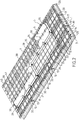
- the figure 4 illustrates in detail the secondary insulating panels 2, 2a, 2b, 2c, 2d, 2e at the level of the singular zone crossed by the sealed pipe 42.
- the other secondary insulating panels 2a, 2b, 2d, 2e of the singular row 50 only comprise metal plates 17 extending in the longitudinal direction of said panels 2a, 2b, 2d, 2e since the edges of the longitudinal ends of each metal sheets of the secondary waterproofing membrane which cover the single row 50 protrude on either side of the longitudinal ends of the panels 2a, 2b, 2d, 2 e and are welded to the metal plates 18 of the secondary insulating panels 2 bordering the singular row 50.
- the secondary insulating panel 2c crossed by the sealed pipe 42 has on either side of the sealed pipe 42 metal plates 51 extending in the transverse direction of said panel 2c. These metal plates 51 are intended for anchoring a secondary closure plate equipped with an opening through which the sealed pipe passes, which will be described in more detail below.
- the studs 19 fixed to the internal plate 10 of the panels are positioned in accordance with the arrangement of the primary insulating panels 6, 6a, 6b, 6c so that each primary insulating panel 6, 6a, 6b, 6c is anchored to the at its four corners and at its side edges on the secondary insulating panels 2, 2a, 2b, 2c, 2d, 2e.
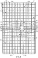
- the figure 5 illustrates in detail the secondary waterproofing membrane 4 in the singular area.
- the secondary sealing membrane 4 comprises a secondary closure plate 53, metallic, of square shape.
- the secondary closure plate 53 has a central circular opening 54 through which passes the sealed pipe, not shown in the figure. figure 5 .
- the secondary closure plate 53 is welded to the aforementioned metal plates 51 which are fixed to the secondary insulating panel 2c.
- the two corrugated metal plates 24a, 24b arranged on either side of the sealed pipe 42 are cut to provide a window having dimensions slightly smaller than that of the secondary closure plate 53.
- the two corrugated metal plates 24a , 24b are sealed overlap welded to the secondary closure plate 53.
- the secondary closure plate 53 has dimensions such that each of its sides meets a series of three corrugations 25a, 25b, 25c, 26a, 26b, 26c.
- the sealed pipe 42 is centered on a position corresponding to the intersection between the guidelines of the central corrugations 25b, 26b of each of these series.
- the guidelines of the central corrugations 25b, 26b are therefore interrupted at the level of the secondary closure plate 53.
- the central corrugations 25b, 26b are closed in a sealed manner with end pieces 55.
- Each end piece 55 has a sole in two. parts sealed to the secondary closure plate 53 and a shell sealed to the central corrugation 25b, 26b at its interruption.
- the secondary closure plate 53 has two pairs of parallel corrugations 56a, 56b, 57a, 57b. Each of the pairs 56a, 56b, 57a, 57b has corrugations perpendicular to those of the other pair.
- the two corrugations 56a and 56b or 57a and 57b of the same pair pass on either side of the circular opening 54 and extend in the extension of the two lateral corrugations 25a, 25c, 26a, 26c of one of the series meeting the secondary closure plate 53.
- the continuity of part of the corrugations 25a,, 25c, 26a,, 26c, meeting the secondary closure plate 53 is ensured, which makes it possible to limit losses elasticity of the secondary waterproofing membrane 4 at the level of the singular zone.
- corrugations 56a, 56b, 57a, 57b of the secondary closure plate 53 protrude outwards from the tank, that is to say in the direction of the supporting structure and are housed inside grooves 14, 15 formed in the internal plate of the secondary insulating panel 2c.
- the secondary closure plate 53 is also equipped with cutouts 58 allowing the passage of studs, not shown on the figure. figure 5 , intended to ensure the fixing of the primary insulating panels 6a, 6b, 6c of the primary thermally insulating barrier.
- the figure 6 illustrates in detail the arrangement of the primary thermally insulating barrier 5 in the singular area of the ceiling wall.
- one of the primary insulating panels 6b of the series of three remarkable panels 6a, 6b, 6c, the orientation of which is perpendicular to that of the other primary insulating panels 6, passes through the sealed pipe 42.
- a closure plate primary 59 of the primary waterproofing membrane 7 is fixed to said primary insulating panel 6b.
- Primary closure plate 59 is provided with an opening for the passage of the sealed pipe 42.
- the sealed pipe 42 is sealed to the primary closure plate 59.
- the three primary insulating panels 6a, 6b, 6c in fact have arrangements of metal plates 60, 61, 62, 63, 64 which are arranged so that they are adapted to the anchoring of the edges of metal sheets of the membrane.
- primary sealing 7 which are arranged in the singular zone, and which have particular dimensions.
- the arrangement of the primary waterproofing membrane 7, in the singular zone of the ceiling wall, is shown in figure 7 .
- Only seven corrugated metal sheets 39a, 39b, 39c, 39d, 39e, 39f, 39g have different dimensions from those of standard corrugated metal sheets 39 covering the standard area of the vessel wall.
- This particular arrangement aims to prevent the cutting of a window in the primary waterproofing membrane 7 to allow the passage of the sealed pipe 42 is made at a corner zone of the corrugated metal sheets 39, which would have the effect of affecting their mechanical strength.
- the two corrugated metal sheets 39a, 39b arranged on either side of the sealed pipe 42 have smaller dimensions than those of the standard corrugated metal sheets 39. Thus, these two corrugated metal sheets 39a, 39b have only two large corrugations for six small corrugations.
- the two corrugated metal sheets 39a, 39b each have a cutout formed along one of their longitudinal edges and centered along the longitudinal dimension of said corrugated metal sheet 39a, 39b. The cutouts together form a window having dimensions slightly smaller than those of the primary closure plate 52.
- the two corrugated metal sheets 39a, 39b are overlapped welded around the entire periphery of the primary closure plate 52.
- the primary closure plate 52 has dimensions such that each of its sides meets a series of two corrugations 40a, 40b, 41a, 41b.
- the sealed pipe 42 is centered on a position corresponding to the intersection between two perpendicular lines d 1 , d 2 , one of which (d 1 ) is parallel to the two corrugations 40a, 40b of one of the series and disposed at an equal distance between these two corrugations 40a, 40b and the other of which (d 2 ) is parallel to the two corrugations 41a, 41b of the other of the series and disposed at an equal distance between them.
- the corrugations 40a, 40b, 41a, 41b meeting the primary closure plate 52 are sealed with end pieces 65.
- the end pieces 65 each have a two-part sole sealed to the primary closure plate 52 and a shell welded in a corrugation-tight manner at its interruption.
- the primary waterproofing membrane comprises five other corrugated sheets compensation 39c, 39d, 39e, 39f, 39g, the dimensions of which are adjusted such that the arrangement of the set of the two sheets 39a, 39b bordering the sealed pipe 45 and the five corrugated sheets 39c, 39d, 39e, 39f , 39g are equivalent to the arrangement of four corrugated metal sheets of standard dimensions.
- the compensation sheet 39c has two high corrugations 40 for six low corrugations 39 while the other four compensation plates 39d, 39e, 39f, 39g each have three high corrugations 40 for six low undulations 39.
- the corrugated metal sheets 24 of the secondary waterproofing membrane 4 have corrugations 66 projecting towards the interior of the tank, unlike the corrugations of the previous embodiment.
- the corrugated metal sheets 24 of the secondary waterproofing membrane 4 also have two series of perpendicular corrugations 66.
- the corrugated metal sheets 24 are fixed to the inner plate 10 of the insulation panels 2 of the barrier. thermally insulating secondary 1 by means of metal plates, not shown, extending in two perpendicular directions which are fixed to the internal plate 10 of the insulating panels 2.
- the outer plate 30 of the insulating panels 6 of the primary thermally insulating barrier 5 have two series of grooves 67 perpendicular to each other so as to form a network of grooves.
- the grooves 67 are thus intended to receive the corrugations 66, projecting towards the interior of the tank, formed on the corrugated metal sheets 24 of the secondary waterproofing membrane 4.
- the secondary waterproofing membrane comprises a general structure identical to that shown in FIG. figure 5 , the only difference residing in the orientation of the corrugations 66 towards the interior of the tank.
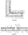
- a sealed and thermally insulating tank wall structure as described above could also be produced at any other type of through element, and in particular at a sump structure 68, as illustrated. on the figure 11 , passing through the bottom wall and intended to accommodate a suction member, for example a pump, not shown.
- the sump structure 68 comprises a conical or primary cylindrical bowl 69, the axis of which is perpendicular to the supporting wall 3.
- the primary cylindrical bowl 69 is continuously connected to the primary sealing membrane 7 which it thus completes with waterproof way.
- the sump structure further comprises a secondary conical or cylindrical bowl 70, concentric with the primary bowl 69, which is connected continuously to the secondary waterproofing membrane 4 which it thus completes in a sealed manner.
- the sump structure 68 also includes insulating materials 71 which are housed between the primary and secondary cylindrical bowls 69, 70 as well as insulating materials 72 interposed between the secondary bowl 70 and the supporting structure 3 in order to ensure continuity. thermal insulation of the primary and secondary thermally insulating barriers 1, 5 at the level of the sump structure 68.
- the tank described above can be used in various types of installation, in particular in an onshore installation or in a floating structure such as an LNG vessel or the like.
- a cut-away view of an LNG carrier 70 shows such a sealed and insulated tank 71 of generally prismatic shape mounted in the double hull 72 of the ship.
- loading / unloading pipes 73 arranged on the upper deck of the ship can be connected, by means of suitable connectors, to a maritime or port terminal for transferring a cargo of LNG from or to the tank 71.
- the figure 9 also represents an example of a maritime terminal comprising a loading and unloading station 75, an underwater pipe 76 and an onshore installation 77.
- the loading and unloading station 75 is a fixed off-shore installation comprising a mobile arm 74 and a tower 78 which supports the movable arm 74.
- the movable arm 74 carries a bundle of insulated flexible pipes 79 which can be connected to the loading / unloading pipes 73.
- the movable arm 74 can be swiveled and adapts to all sizes of LNG carriers.
- a connecting pipe, not shown, extends inside the tower 78.
- the loading and unloading station 75 allows the loading and unloading of the LNG carrier 70 from or to the onshore installation 77.
- the latter comprises liquefied gas storage tanks 80 and connecting pipes 81 connected by the underwater pipe 76 to the loading or unloading station 75.
- the underwater pipe 76 allows the transfer of the liquefied gas between the loading or unloading station 75 and the shore installation 77 over a great distance, for example 5 km, which makes it possible to keep the LNG carrier 70 at a great distance from the coast during loading and unloading operations.
- pumps on board the ship 70 and / or pumps fitted to the shore installation 77 and / or pumps fitted to the loading and unloading station 75 are used.
Landscapes
- Engineering & Computer Science (AREA)
- Mechanical Engineering (AREA)
- General Engineering & Computer Science (AREA)
- Physics & Mathematics (AREA)
- Thermal Sciences (AREA)
- Chemical & Material Sciences (AREA)
- Combustion & Propulsion (AREA)
- Ocean & Marine Engineering (AREA)
- Filling Or Discharging Of Gas Storage Vessels (AREA)
Description
L'invention se rapporte au domaine des cuves, étanches et thermiquement isolantes, à membranes, pour le stockage et/ou le transport de fluide, tel qu'un fluide cryogénique.The invention relates to the field of sealed and thermally insulating tanks with membranes, for the storage and / or transport of fluid, such as a cryogenic fluid.
Des cuves étanches et thermiquement isolantes à membranes sont notamment employées pour le stockage de gaz naturel liquéfié (GNL), qui est stocké, à pression atmosphérique, à environ -162°C.Sealed and thermally insulating membrane tanks are used in particular for the storage of liquefied natural gas (LNG), which is stored, at atmospheric pressure, at approximately -162 ° C.
Le document
Les barrières thermiquement isolantes primaire et secondaire comportent respectivement une pluralité de panneaux isolants primaires et secondaires de forme parallélépipédique rectangle qui sont juxtaposés selon des rangées parallèles. Les directions longitudinales des panneaux isolants primaires sont parallèles à celles des panneaux isolants secondaires. Chaque panneau isolant primaire est disposé à cheval sur quatre panneaux isolants secondaires. En outre, chaque panneau isolant primaire est ancré au niveau de chacun de ses quatre coins sur un organe d'ancrage fixé au centre de la face interne d'un des panneaux isolants secondaires qu'il chevauche. Les membranes d'étanchéité primaire et secondaire sont chacune constituées d'une pluralité de tôles métalliques comportant des ondulations et leur permettant de se déformer sous l'effet des sollicitations thermiques et mécaniques générées par le fluide emmagasiné dans la cuve. Les tôles métalliques de la membrane d'étanchéité secondaire sont ancrées sur les panneaux isolants secondaires et les tôles métalliques de la membrane d'étanchéité primaire sont ancrées sur les panneaux isolants primaires.The primary and secondary thermally insulating barriers respectively comprise a plurality of primary and secondary insulating panels of rectangular parallelepiped shape which are juxtaposed in parallel rows. The longitudinal directions of the primary insulation panels are parallel to those of the secondary insulation panels. Each primary insulating panel is placed astride four secondary insulating panels. In addition, each primary insulating panel is anchored at each of its four corners on an anchoring member fixed to the center of the internal face of one of the secondary insulating panels which it overlaps. The primary and secondary waterproofing membranes each consist of a plurality of metal sheets comprising corrugations and allowing them to deform under the effect of stresses. thermal and mechanical generated by the fluid stored in the tank. The metal sheets of the secondary waterproofing membrane are anchored to the secondary insulation panels and the metal sheets of the primary waterproofing membrane are anchored to the primary insulation panels.
Les cuves étanches et thermiquement isolantes pour le stockage de gaz naturel liquéfié sont équipées de conduites étanches passant chacune au travers d'une zone singulière d'une des parois pour définir un passage entre l'espace intérieur de la cuve et l'extérieur de la cuve. C'est notamment le cas au niveau de la paroi de plafond qui est traversée par une conduite étanche débouchant en partie supérieure de l'espace interne de la cuve et définissant ainsi un passage de vapeur entre l'espace intérieur de la cuve et un collecteur de vapeur agencé à l'extérieur de la cuve. Une telle conduite étanche permet ainsi d'éviter de générer, à l'intérieur de la cuve, une surpression susceptible d'être produite par l'évaporation naturelle du gaz naturel liquéfié stocké à l'intérieur de la cuve.The sealed and thermally insulating tanks for the storage of liquefied natural gas are equipped with sealed pipes each passing through a singular zone of one of the walls to define a passage between the interior space of the tank and the outside of the tank. This is particularly the case at the level of the ceiling wall which is crossed by a sealed pipe opening into the upper part of the internal space of the tank and thus defining a vapor passage between the internal space of the tank and a manifold. of steam arranged outside the tank. Such a sealed pipe thus makes it possible to avoid generating, inside the tank, an excess pressure capable of being produced by the natural evaporation of the liquefied natural gas stored inside the tank.
Si une telle conduite étanche présente généralement un diamètre plus faible que la largeur des panneaux d'isolation primaires et secondaires tels que décrits dans le document
De plus, une découpe ménagée dans un bord d'un panneau isolant est également susceptible de conduire à solliciter davantage certaines zones des plaques métalliques bordant la conduite étanche, dans la zone singulière de la paroi de cuve.In addition, a cutout made in an edge of an insulating panel is also likely to lead to more stress certain areas of the metal plates bordering the sealed pipe, in the singular area of the tank wall.
De problèmes similaires sont également susceptibles de se poser dans la paroi inférieure de la cuve, par exemple au niveau d'une structure de puisard ou de tout autre élément traversant une zone singulière de la paroi de cuve.Similar problems are also likely to arise in the lower wall of the tank, for example at the level of a sump structure or any other element passing through a singular zone of the tank wall.
Le document
Une idée à la base de l'invention est de proposer une cuve à structure multicouche équipée d'un élément traversant passant au travers d'une zone singulière d'une paroi de la cuve et présentant des panneaux isolants primaires ancrés à cheval sur plusieurs panneaux secondaires et dans laquelle la structure de la cuve dans ladite zone singulière est simple et ne présente qu'un impact négatif réduit sur le résistance aux contraintes thermomécaniques de la cuve.An idea at the basis of the invention is to provide a tank with a multilayer structure equipped with a through element passing through a singular zone of a wall of the tank and having primary insulating panels anchored astride several panels. secondary and in which the structure of the tank in said singular zone is simple and has only a reduced negative impact on the resistance to thermomechanical stresses of the tank.
Selon un mode de réalisation, l'invention fournit une cuve étanche et thermiquement isolante destinée au stockage d'un fluide, ladite cuve comportant une paroi de cuve fixée à une structure porteuse, la paroi comportant successivement, dans le sens de l'épaisseur depuis l'extérieur vers l'intérieur de la cuve, une barrière thermiquement isolante secondaire retenue contre la structure porteuse, une membrane d'étanchéité secondaire portée par la barrière thermiquement isolante secondaire, une barrière thermiquement isolante primaire reposant contre la membrane d'étanchéité secondaire et une membrane d'étanchéité primaire portée par la barrière thermiquement isolante primaire et destinée à être en contact avec le fluide contenu dans la cuve ;
la barrière thermiquement isolante secondaire comportant des panneaux isolants secondaires juxtaposés, retenus contre la structure porteuse et présentant une forme parallélépipédique rectangle ayant une direction longitudinale, chaque panneau isolant secondaire présentant une face interne, opposée à la paroi porteuse, équipée d'au moins un organe d'ancrage ;
la barrière thermiquement isolante primaire comportant des panneaux isolants primaires juxtaposés présentant une forme parallélépipédique rectangle ayant une direction longitudinale, chaque panneau isolant primaire étant disposé à cheval sur au moins quatre panneaux isolants secondaires et ancré audit organe d'ancrage de chacun des panneaux isolants secondaires que ledit panneau isolant primaire chevauche ;
la cuve étanche étant équipée d'un élément traversant passant au travers d'une zone singulière de la paroi ;
la barrière thermiquement isolante primaire comprenant dans la zone singulière de la paroi de cuve une série primaire de panneaux isolants primaires présentant des directions longitudinales parallèles les unes aux autres ;
la barrière thermiquement isolante secondaire comprenant dans la zone singulière de la paroi une série secondaire de panneaux isolants secondaires présentant des directions longitudinales parallèles les unes aux autres ;
la série primaire et la série secondaire étant disposées l'une par rapport à l'autre de telle sorte que les directions longitudinales des panneaux isolants primaires de la série primaire soient perpendiculaires aux directions longitudinales des panneaux isolants secondaires de la série secondaire ;
l'élément traversant s'étendant dans le sens de l'épaisseur de la zone singulière de la paroi et passant successivement au travers d'une ouverture ménagée dans un des panneaux isolants secondaires de la série secondaire, au travers d'une ouverture ménagée dans la membrane d'étanchéité secondaire, au travers d'une ouverture ménagée dans un des panneaux isolants primaires de la série primaire et au travers d'une ouverture ménagée dans la membrane d'étanchéité primaire.According to one embodiment, the invention provides a sealed and thermally insulating tank intended for the storage of a fluid, said tank comprising a tank wall fixed to a supporting structure, the wall comprising successively, in the direction of the thickness from the exterior to the interior of the vessel, a secondary thermally insulating barrier retained against the supporting structure, a secondary waterproofing membrane carried by the secondary thermally insulating barrier, a primary thermally insulating barrier resting against the secondary waterproofing membrane and a primary waterproofing membrane carried by the primary thermally insulating barrier and intended to be in contact with the fluid contained in the tank;
the secondary thermally insulating barrier comprising juxtaposed secondary insulating panels, held against the supporting structure and having a rectangular parallelepiped shape having a longitudinal direction, each secondary insulating panel having an internal face, opposite to the supporting wall, equipped with at least one member anchoring;
the primary thermally insulating barrier comprising juxtaposed primary insulating panels having a rectangular parallelepiped shape having a longitudinal direction, each primary insulating panel being disposed astride at least four secondary insulating panels and anchored to said anchoring member of each of the secondary insulating panels that said primary insulating panel overlaps;
the sealed tank being equipped with a through element passing through a singular area of the wall;
the primary thermally insulating barrier comprising in the singular zone of the tank wall a primary series of primary insulating panels having longitudinal directions parallel to one another;
the secondary thermally insulating barrier comprising in the singular zone of the wall a secondary series of secondary insulating panels having longitudinal directions parallel to each other;
the primary series and the secondary series being disposed with respect to each other such that the longitudinal directions of the primary insulating panels of the primary series are perpendicular to the longitudinal directions of the secondary insulating panels of the secondary series;
the through element extending in the direction of the thickness of the singular zone of the wall and passing successively through an opening made in one of the secondary insulating panels of the secondary series, through an opening made in the secondary waterproofing membrane, through an opening made in one of the primary insulating panels of the primary series and through an opening made in the primary waterproofing membrane.
Ainsi, grâce à l'orientation des panneaux isolants primaires de la série primaire perpendiculairement à l'orientation des panneaux isolants secondaires de la série secondaire, l'élément traversant passe au travers d'ouvertures à pourtour continu d'un des panneaux isolants primaires et d'un des panneaux isolants secondaires sans qu'une découpe ne soit formée dans un bord desdits panneaux isolants alors que chacun des panneaux isolants primaires est décalé par rapport aux panneaux isolants secondaires et à cheval sur plusieurs d'entre eux. En d'autres termes, l'ouverture traversée par l'élément traversant est disjointe des bords du panneau primaire, respectivement secondaire.Thus, thanks to the orientation of the primary insulating panels of the primary series perpendicular to the orientation of the secondary insulating panels of the secondary series, the through element passes through openings with continuous periphery of one of the primary insulating panels and of one of the secondary insulating panels without a cutout being formed in one edge of said insulating panels while each of the primary insulating panels is offset with respect to the secondary insulating panels and straddling several of them. In other words, the opening crossed by the through element is separate from the edges of the primary panel, respectively secondary.
La réalisation d'un tel agencement dans la zone singulière de la paroi de cuve est particulièrement simple et permet d'obtenir de bonnes caractéristiques de résistance aux contraintes thermomécaniques au niveau de la zone singulière.The realization of such an arrangement in the singular zone of the vessel wall is particularly simple and makes it possible to obtain good characteristics of resistance to thermomechanical stresses at the level of the singular zone.
Selon d'autres modes de réalisation avantageux, une telle cuve étanche et thermiquement isolante peut présenter une ou plusieurs des caractéristiques suivantes :
- les panneaux isolants secondaires, disposés dans une zone restante située autour de la zone singulière de la paroi, sont agencés en rangées parallèles et présentent des directions longitudinales orientées parallèlement les unes aux autres.
- les panneaux isolants primaires, disposés dans ladite zone restante, sont agencés en rangées parallèles et présentent des directions longitudinales orientées parallèlement les unes aux autres.
- les directions longitudinales des panneaux isolants secondaires de la zone restante sont parallèles aux directions longitudinales des panneaux isolants primaires de la zone restante. Ainsi, les directions longitudinales des panneaux isolants de l'une des séries primaire et secondaire sont orientées perpendiculairement aux directions longitudinales des panneaux isolants primaires et secondaires de la zone restante et les directions longitudinales des panneaux isolants de l'autre des séries primaire et secondaire sont orientées parallèlement aux directions longitudinales des panneaux isolants primaires et secondaires de la zone restante.
- la série dont les panneaux isolants présentent des directions longitudinales orientées perpendiculairement aux directions longitudinales des panneaux isolants primaires et secondaires de la zone restante est la série primaire.
- les panneaux isolants primaires présentent chacun une dimension longitudinale égale à n fois leur dimension transversale, n étant un nombre entier supérieur à 1, et la série primaire comporte n panneaux isolants primaires.
- les panneaux isolants primaires de la zone restante présentent des dimensions longitudinales et transversales identiques à celles des panneaux isolants primaires de la série primaire.
- la série secondaire de panneaux isolants secondaires comporte une rangée de panneaux isolants secondaires s'étendant d'un bord à l'autre de la paroi de cuve selon une direction transversale perpendiculaire à la direction longitudinale desdits panneaux isolants secondaires et les panneaux isolants secondaires de la série secondaire présentent une dimension longitudinale inférieure à la dimension longitudinale des panneaux isolants secondaires dans la zone restante.
- la dimension longitudinale des panneaux isolants secondaire de la série secondaire est un multiple entier de la distance inter-ondulations entre deux ondulations successives de la membrane d'étanchéité secondaire.
- l'ouverture au travers de laquelle passe l'élément traversant qui est ménagée dans le panneau isolant secondaire de la série secondaire est disposée au centre dudit panneau isolant secondaire.
- l'ouverture au travers de laquelle passe l'élément traversant qui est ménagée dans le panneau isolant primaire de la série primaire est centrée au milieu de la dimension transversale dudit panneau isolant primaire.
- l'élément traversant présente une section inférieure à la dimension transversale des panneaux isolants primaire et secondaire qu'il traverse.
- chaque panneau isolant secondaire est associé aux panneaux isolants secondaires adjacents par l'intermédiaire d'une pluralité d'éléments de pontage, chaque élément de pontage étant disposé à cheval entre au moins ledit panneau isolant secondaire et un dit panneau isolant secondaire adjacent et étant d'une part fixé à un bord de la face interne de l'un des panneaux isolants secondaires et, d'autre part, à un bord en vis-à-vis de la face interne de l'autre panneau isolant secondaire de manière à s'opposer à un écartement mutuel desdits panneaux isolants secondaires adjacents.
- les éléments de pontage sont des plaques de pontage qui présentent chacune une face externe reposant contre la face interne de chacun des panneaux isolants secondaires adjacents et une face interne portant la membrane d'étanchéité secondaire.
- la face interne de chaque panneau isolant secondaire est équipée de platines métalliques, la membrane d'étanchéité secondaire comportant dans la zone singulière de la paroi une plaque de fermeture secondaire équipée de l' ouverture de la membrane d'étanchéité secondaire au travers de laquelle passe l'élément traversant ; ladite plaque de fermeture secondaire étant soudée sur les platines métalliques du panneau isolant secondaire équipé de l'ouverture.
- la plaque de fermeture secondaire est soudée sur l'élément traversant.
- la membrane d'étanchéité secondaire comporte une pluralité de tôles métalliques secondaires ondulées soudées les unes aux autres de manière étanche et comprenant chacune au moins deux ondulations perpendiculaires, lesdites tôles métalliques secondaires étant soudées sur les platines métalliques des panneaux isolants secondaires, les tôles métalliques secondaires ondulées adjacentes à la plaque de fermeture secondaire étant soudées sur celle-ci.
- l'élément traversant est centré sur une position correspondant à l'intersection entre les lignes directrices de deux ondulations perpendiculaires l'une à l'autre des tôles métalliques secondaires.
- les deux ondulations perpendiculaires l'une à l'autre et dont l'intersection des lignes directrices correspond au centre de l'élément traversant sont fermées de manière étanche au niveau de la plaque de fermeture secondaire avec des pièces de bout comportant chacune une semelle soudée de manière étanche à la plaque de fermeture secondaire et une coque soudée de manière étanche à ladite ondulation.
- la plaque de fermeture secondaire comporte deux paires d'ondulations parallèles, les deux ondulations d'une même paire passant de part et d'autre de l'ouverture et s'étendant chacune dans le prolongement d'une ondulation d'une des tôles métalliques ondulées secondaires.
- selon un mode de réalisation, les ondulations des tôles métalliques secondaires font saillie vers l'extérieur de la cuve en direction de la structure porteuse, la face interne des panneaux isolants secondaires, présentant des rainures perpendiculaires recevant les ondulations des tôles métalliques secondaires.
- selon un autre mode de réalisation, les ondulations des tôles métalliques secondaires font saillie vers l'intérieur de la cuve, les panneaux isolants primaires présentant chacun une face externe présentant des rainures perpendiculaires recevant les ondulations des tôles métalliques ondulées de la membrane d'étanchéité secondaire.
- la membrane d'étanchéité primaire comporte dans la zone singulière de la paroi une plaque de fermeture primaire équipée de l'ouverture de la membrane d'étanchéité primaire au travers de laquelle passe l'élément traversant ; ladite plaque de fermeture primaire étant soudée de manière étanche à l'élément traversant et étant fixée sur le panneau isolant primaire équipé de l'ouverture.
- chaque panneau isolant primaire de la barrière thermiquement isolante primaire présente une face interne, opposée à la paroi porteuse ; ladite face interne étant équipée de platines métalliques, la membrane d'étanchéité primaire comportant une pluralité de tôles métalliques primaires ondulées soudées les unes aux autres de manière étanche et comprenant chacune au moins deux ondulations perpendiculaires, lesdites tôles métalliques primaires étant soudées sur les platines métalliques des panneaux isolants primaires, les tôles métalliques primaires ondulées adjacentes à la plaque de fermeture primaire étant soudées sur celle-ci.
- l'élément traversant est centré sur une position correspondant à l'intersection entre une première et une seconde droite, la première droite étant parallèle à une première paire d'ondulations parallèles de la membrane d'étanchéité primaire et disposée à égale distance entre les ondulations de la première paire et la seconde droite étant parallèle à une seconde paire d'ondulations parallèles qui sont perpendiculaires aux ondulations de la première paire et disposée à égale distance entre les ondulations de la seconde paire.
- les ondulations interrompues par la plaque de fermeture primaire sont fermées de manière étanche au niveau de la plaque de fermeture primaire avec des pièces de bout comportant chacune une semelle soudée de manière étanche à la plaque de fermeture primaire et une coque soudée de manière étanche à ladite ondulation.
- l'élément traversant est une conduite étanche passant au travers d'une zone singulière de la paroi pour définir un passage entre l'espace intérieur de la cuve et l'extérieur de la cuve.
- l'élément traversant est une structure de puisard.
- La structure de puisard comporte :
- une cuvette primaire raccordée à la membrane d'étanchéité primaire,
- une cuvette secondaire, concentrique à la cuvette primaire, et raccordée à la membrane d'étanchéité secondaire,
- des matières isolantes primaires logées entre les cuvettes primaires et secondaires ;
- des matières isolantes secondaires interposées entre la cuvette secondaire et la structure porteuse.
- the secondary insulating panels, arranged in a remaining area located around the singular area of the wall, are arranged in parallel rows and have longitudinal directions oriented parallel to each other.
- the primary insulating panels, arranged in said remaining zone, are arranged in parallel rows and have longitudinal directions oriented parallel to each other.
- the longitudinal directions of the secondary insulating panels of the remaining area are parallel to the longitudinal directions of the primary insulating panels of the remaining area. Thus, the longitudinal directions of the insulating panels of one of the primary and secondary series are oriented perpendicular to the longitudinal directions of the primary and secondary insulating panels of the remaining area and the longitudinal directions of the insulating panels of the other of the primary and secondary series are oriented parallel to the longitudinal directions of the primary and secondary insulation panels of the remaining area.
- the series of which the insulating panels have longitudinal directions oriented perpendicular to the longitudinal directions of the primary and secondary insulating panels of the remaining zone is the primary series.
- the primary insulating panels each have a longitudinal dimension equal to n times their transverse dimension, n being an integer greater than 1, and the primary series comprises n primary insulating panels.
- the primary insulating panels of the remaining zone have longitudinal and transverse dimensions identical to those of the primary insulating panels of the primary series.
- the secondary series of secondary insulating panels comprises a row of secondary insulating panels extending from one edge to the other of the tank wall in a transverse direction perpendicular to the longitudinal direction of said secondary insulating panels and the secondary insulating panels of the secondary series have a longitudinal dimension smaller than the longitudinal dimension of the secondary insulation panels in the remaining area.
- the longitudinal dimension of the secondary insulating panels of the secondary series is an integer multiple of the inter-corrugation distance between two successive corrugations of the secondary waterproofing membrane.
- the opening through which passes the through element which is formed in the secondary insulating panel of the secondary series is arranged in the center of said secondary insulating panel.
- the opening through which passes the through element which is formed in the primary insulating panel of the primary series is centered in the middle of the transverse dimension of said primary insulating panel.
- the through element has a section smaller than the transverse dimension of the primary and secondary insulating panels that it passes through.
- each secondary insulating panel is associated with the adjacent secondary insulating panels by means of a plurality of bridging elements, each bridging element being disposed astride at least said secondary insulating panel and one said adjacent secondary insulating panel and being d 'on the one hand fixed to an edge of the inner face of one of the secondary insulating panels and, on the other hand, to an edge facing the inner face of the other secondary insulating panel so as to s 'oppose a mutual separation of said adjacent secondary insulating panels.
- the bridging elements are bridging plates which each have an outer face resting against the inner face of each of the adjacent secondary insulating panels and an inner face carrying the secondary waterproofing membrane.
- the internal face of each secondary insulating panel is equipped with metal plates, the secondary waterproofing membrane comprising in the singular zone of the wall a secondary closing plate equipped with the opening of the secondary waterproofing membrane through which passes the through element; said secondary closure plate being welded to the metal plates of the secondary insulating panel equipped with the opening.
- the secondary closure plate is welded to the through element.
- the secondary waterproofing membrane comprises a plurality of corrugated secondary metal sheets welded to each other in a sealed manner and each comprising at least two perpendicular corrugations, said secondary metal sheets being welded to the metal plates of the secondary insulating panels, the secondary metal sheets corrugated waves adjacent to the secondary closure plate being welded to it.
- the through element is centered on a position corresponding to the intersection between the guidelines of two corrugations perpendicular to each other of the secondary metal sheets.
- the two corrugations perpendicular to each other and the intersection of the guidelines of which corresponds to the center of the traversing element are sealed in a sealed manner at the level of the secondary closure plate with end pieces each comprising a welded flange sealed to the secondary closure plate and a shell sealed to said corrugation.
- the secondary closure plate comprises two pairs of parallel corrugations, the two corrugations of the same pair passing on either side of the opening and each extending in the extension of a corrugation of one of the metal sheets secondary wavy.
- according to one embodiment, the corrugations of the secondary metal sheets protrude outwardly from the tank in the direction of the supporting structure, the internal face of the secondary insulating panels, having perpendicular grooves receiving the corrugations of the secondary metal sheets.
- according to another embodiment, the corrugations of the secondary metal sheets protrude towards the interior of the tank, the primary insulating panels each having an external face having perpendicular grooves receiving the undulations of the corrugated metal sheets of the secondary waterproofing membrane .
- the primary waterproofing membrane comprises in the singular region of the wall a primary closure plate equipped with the opening of the primary waterproofing membrane through which the through element passes; said primary closure plate being welded in a sealed manner to the through element and being fixed to the primary insulating panel equipped with the opening.
- each primary insulating panel of the primary thermally insulating barrier has an internal face, opposite to the bearing wall; said internal face being equipped with metal plates, the primary waterproofing membrane comprising a plurality of corrugated primary metal sheets welded to each other in a sealed manner and each comprising at least two corrugations perpendicular, said primary metal sheets being welded to the metal plates of the primary insulating panels, the corrugated primary metal sheets adjacent to the primary closure plate being welded to the latter.
- the through element is centered on a position corresponding to the intersection between a first and a second straight line, the first straight line being parallel to a first pair of parallel corrugations of the primary waterproofing membrane and disposed at an equal distance between the corrugations of the first pair and the second straight line being parallel to a second pair of parallel corrugations which are perpendicular to the corrugations of the first pair and disposed equidistant between the corrugations of the second pair.
- the corrugations interrupted by the primary closure plate are closed in a sealed manner at the level of the primary closure plate with end pieces each comprising a sole welded in a sealed manner to the primary closure plate and a shell sealed in a sealed manner to said ripple.
- the through element is a sealed pipe passing through a singular area of the wall to define a passage between the interior space of the tank and the outside of the tank.
- the through element is a sump structure.
- The sump structure includes:
- a primary cuvette connected to the primary waterproofing membrane,
- a secondary cuvette, concentric with the primary cuvette, and connected to the secondary waterproofing membrane,
- primary insulating materials housed between the primary and secondary cuvettes;
- secondary insulating materials interposed between the secondary bowl and the supporting structure.
Une telle cuve peut faire partie d'une installation de stockage terrestre, par exemple pour stocker du GNL ou être installée dans une structure flottante, côtière ou en eau profonde, notamment un navire méthanier, éthanier, une unité flottante de stockage et de regazéification (FSRU), une unité flottante de production et de stockage déporté (FPSO) et autres.Such a tank can be part of an onshore storage installation, for example to store LNG or be installed in a floating, coastal or deep water structure, in particular an LNG vessel, ethane carrier, a floating unit. storage and regasification unit (FSRU), a floating production and remote storage unit (FPSO) and others.
Selon un mode de réalisation, un navire pour le transport d'un fluide comporte une double coque et une cuve précitée disposée dans la double coque.According to one embodiment, a vessel for transporting a fluid comprises a double hull and a above-mentioned tank arranged in the double hull.
Selon un mode de réalisation, l'invention fournit aussi un procédé de chargement ou déchargement d'un tel navire, dans lequel on achemine un fluide à travers des canalisations isolées depuis ou vers une installation de stockage flottante ou terrestre vers ou depuis la cuve du navire.According to one embodiment, the invention also provides a method for loading or unloading such a vessel, in which a fluid is conveyed through isolated pipes from or to a floating or terrestrial storage installation to or from the tank of the vessel. ship.
Selon un mode de réalisation, l'invention fournit aussi un système de transfert pour un fluide, le système comportant le navire précité, des canalisations isolées agencées de manière à relier la cuve installée dans la coque du navire à une installation de stockage flottante ou terrestre et une pompe pour entraîner un fluide à travers les canalisations isolées depuis ou vers l'installation de stockage flottante ou terrestre vers ou depuis la cuve du navire.According to one embodiment, the invention also provides a transfer system for a fluid, the system comprising the aforementioned vessel, isolated pipes arranged so as to connect the tank installed in the hull of the vessel to a floating or land storage installation. and a pump for driving fluid through insulated pipelines from or to the floating or onshore storage facility to or from the vessel of the vessel.
L'invention sera mieux comprise, et d'autres buts, détails, caractéristiques et avantages de celle-ci apparaîtront plus clairement au cours de la description suivante de plusieurs modes de réalisation particuliers de l'invention, donnés uniquement à titre illustratif et non limitatif, en référence aux dessins annexés.
- La
figure 1 est une vue en coupe d'une cuve étanche et thermiquement isolante de stockage de gaz naturel liquéfié au niveau d'une zone d'angle entre deux parois. - La
figure 2 est une vue en perspective, écorchée, d'une paroi de la cuve dans une zone standard. - La
figure 3 est une vue en coupe d'une paroi de plafond de la cuve dans une zone singulière au travers de laquelle passe une conduite étanche de collecte de fluide, la coupe étant réalisée selon l'axe III-III de lafigure 7 . - La
figure 4 est une vue de dessous de la paroi de plafond représentant la barrière thermiquement isolante secondaire au niveau de la zone singulière. - La
figure 5 est une vue écorchée de dessous de la membrane d'étanchéité secondaire au niveau de la zone singulière. - La
figure 6 est une vue écorchée de dessous de la paroi de plafond au niveau de la zone singulière ; la membrane d'étanchéité primaire n'étant pas représentée afin de permettre l'observation de la barrière thermiquement isolante primaire. - La
figure 7 est une vue de dessous de la paroi de plafond représentant la membrane d'étanchéité primaire au niveau de la zone singulière. - La
figure 8 est une représentation schématique des barrières thermiquement isolantes primaire et secondaire au niveau de la zone singulière, les contours des panneaux isolants primaires étant illustrés en traits pleins et les contours des panneaux isolants secondaires étant illustrés en traits pointillés. - La
figure 9 est une représentation schématique écorchée d'une cuve de navire méthanier comportant une cuve étanche et thermiquement isolante de stockage d'un fluide et d'un terminal de chargement/déchargement de cette cuve. - La
figure 10 est une vue en coupe d'une cuve étanche et thermiquement isolante de stockage d'un fluide au niveau d'une zone d'angle entre deux parois selon un autre mode de réalisation. - La
figure 11 est une vue en coupe analogue à celle de lafigure 3 qui illustre une paroi de fond de la cuve dans une zone singulière au travers de laquelle passe une structure de puisard.
- The
figure 1 is a sectional view of a sealed and thermally insulating tank for storing liquefied natural gas at the level of a corner zone between two walls. - The
figure 2 is a perspective view, cut away, of a vessel wall in a standard area. - The
figure 3 is a sectional view of a ceiling wall of the tank in a singular zone through which passes a sealed fluid collection pipe, the section being taken along the axis III-III of thefigure 7 . - The
figure 4 is a bottom view of the ceiling wall showing the secondary thermally insulating barrier at the level of the singular zone. - The
figure 5 is a cutaway view from below of the secondary waterproofing membrane at the singular area. - The
figure 6 is a cutaway view from below of the ceiling wall at the level of the singular zone; the primary waterproofing membrane not being shown in order to allow observation of the primary thermally insulating barrier. - The
figure 7 is a view from below of the ceiling wall showing the primary waterproofing membrane at the level of the singular zone. - The
figure 8 is a schematic representation of the primary and secondary thermally insulating barriers at the level of the singular zone, the contours of the primary insulating panels being illustrated in solid lines and the contours of the secondary insulating panels being illustrated in dotted lines. - The
figure 9 is a cut-away schematic representation of an LNG vessel tank comprising a sealed and thermally insulating tank for storing a fluid and a loading / unloading terminal for this tank. - The
figure 10 is a sectional view of a sealed and thermally insulating tank for storing a fluid at the level of a corner zone between two walls according to another embodiment. - The
figure 11 is a sectional view similar to that of thefigure 3 which illustrates a bottom wall of the tank in a singular zone through which a sump structure passes.
Par convention, les termes «externe » et « interne » sont utilisés pour définir la position relative d'un élément par rapport à un autre, par référence à l'intérieur et à l'extérieur de la cuve. En outre, on entend par direction longitudinale d'un élément parallélépipédique rectangle, la direction correspondant au côté de plus grande dimension du rectangle.By convention, the terms “external” and “internal” are used to define the relative position of an element with respect to another, by reference to the interior and exterior of the tank. In addition, the term “longitudinal direction” of a rectangular parallelepiped element is understood to mean the direction corresponding to the side of greatest dimension of the rectangle.
En relation avec les
La structure porteuse 3 peut notamment être une tôle métallique autoporteuse ou, plus généralement, tout type de cloison rigide présentant des propriétés mécaniques appropriées. La structure porteuse 3 peut notamment être formée par la coque ou la double coque d'un navire. La structure porteuse 3 comporte une pluralité de parois définissant la forme générale de la cuve, habituellement une forme polyédrique.The supporting
La barrière thermiquement isolante secondaire 1 comporte une pluralité de panneaux isolants 2 ancrés sur la structure porteuse 3 au moyen de cordons de résine, non illustrés, et/ou de goujons 8 soudés sur la structure porteuse 3. Les panneaux isolants 2 présentent sensiblement une forme de parallélépipède rectangle.The secondary thermally insulating barrier 1 comprises a plurality of insulating
Comme illustré sur la
Dans une zone standard d'une paroi, tel que représenté sur la
Comme représenté sur la
Les rainures 14, 15 traversent intégralement l'épaisseur de la plaque interne 10 et débouchent ainsi au niveau de la couche de mousse polymère isolante 9. Par ailleurs, les panneaux isolants 2 comportent dans les zones de croisement entre les rainures 14, 15, des orifices de dégagement 16 ménagés dans la couche de mousse polymère isolante 9. Les orifices de dégagements 16 permettent le logement des zones de nœud, formés aux intersections entre les ondulations des tôles métalliques de la membrane d'étanchéité secondaire 4.The
Par ailleurs, la plaque interne 10 est équipée de platines métalliques 17, 18 pour l'ancrage du bord des tôles métalliques ondulées de la membrane d'étanchéité secondaire 4 sur les panneaux isolants 2. Les platines métalliques 17, 18 s'étendent selon deux directions perpendiculaires qui sont chacune parallèles à deux côtés opposés des panneaux isolants 2. Les platines métalliques 17, 18 sont fixées sur la plaque interne 10 du panneau isolant 2, par des vis, des rivets ou des agrafes, par exemple. Les platines métalliques 17, 18 sont mises en place dans des évidements ménagés dans la plaque interne 10 de telle sorte que la surface interne des platines métalliques 17, 18 affleure la surface interne de la plaque interne 10.Furthermore, the
La plaque interne 10 est également équipée de goujons filetés 19 faisant saillie vers l'intérieur de la cuve, et destinés à assurer la fixation de la barrière thermiquement isolante primaire 5 sur les panneaux isolants 2 de la barrière thermiquement isolante secondaire 1.The
Afin d'assurer la fixation des panneaux isolants 2 aux goujons 8 fixés à la structure porteuse 3, les panneaux isolants 2 sont pourvues de puits cylindrique 20, représentés sur la
Par ailleurs, la plaque interne 10 présente le long de ses bords, dans chaque intervalle entre deux rainures successives 14, 15, un décrochement recevant des plaques de pontage 22 qui sont chacune disposées à cheval entre deux panneaux isolants 2 adjacents, en enjambant l'interstice 12 entre les panneaux isolants 2. Chaque plaque de pontage 22 est fixée contre chacun des deux panneaux isolants 2 adjacents de manière à s'opposer à leur écartement mutuel. Les plaques de pontage 22 présentent une forme parallélépipédique rectangle et sont par exemple constituées d'une plaque de bois contreplaqué. La face externe des plaques de pontage 22 est fixée contre le fond des décrochements 21. La profondeur des décrochements 21 est sensiblement égale à l'épaisseur des plaques de pontage 22 de telle sorte que la face interne des plaques de pontage 22 parvienne sensiblement au niveau des autres zones planes de la plaque interne 10 du panneau isolant. Ainsi, les plaques de pontage 22 sont en mesure d'assurer une continuité dans le portage de la membrane d'étanchéité secondaire 4.Furthermore, the
De manière à assurer une bonne répartition des efforts de liaison entre les panneaux adjacents, une pluralité de plaques de pontage 22 s'étend le long de chaque bord de la plaque interne 10 des panneaux isolants 2, une plaque de pontage 22 étant disposée dans chaque intervalle entre deux rainures voisines 14, 15 d'une série de rainures parallèles. Les plaques de pontage 22 peuvent être fixées contre la plaque interne 10 des panneaux isolants 2 par tous moyens appropriés. Il a toutefois été constaté que la combinaison de l'application d'une colle entre la face externe des plaques de pontage 22 et la plaque interne 10 des panneaux isolants 2 et de l'utilisation d'organes de fixation mécanique, tels que des agrafes, permettant une mise en pression des plaques de pontage 22 contre les panneaux isolants 2, était particulièrement avantageuse.In order to ensure a good distribution of the connecting forces between the adjacent panels, a plurality of bridging
La membrane d'étanchéité secondaire 4 comporte une pluralité de tôles métalliques ondulées 24 ayant chacune une forme sensiblement rectangulaire. Les tôles métalliques ondulées 24 sont disposées de manière décalée par rapport aux panneaux isolants 2 de la barrière thermiquement isolante secondaire 1 de telle sorte que chacune desdites tôles métalliques ondulées 24 s'étende conjointement sur quatre panneaux isolants 2 adjacents. Chaque tôle métallique ondulée 24 présente une première série d'ondulations 25 parallèles s'étendant selon une première direction et une seconde série d'ondulations 26 parallèles s'étendant selon une seconde direction. Les directions des séries d'ondulations 25, 26 sont perpendiculaires. Chacune des séries d'ondulations 25, 26 est parallèle à deux bords opposés de la tôle métallique ondulée 24. Les ondulations 25, 26 font saillie vers l'extérieur de la cuve, c'est-à-dire en direction de la structure porteuse 3. La tôle métallique ondulée 24 comporte entre les ondulations 25, 26, une pluralité de surfaces planes. Au niveau de chaque croisement entre deux ondulations 25, 26, la tôle métallique comporte une zone de nœud présentant un sommet en saillie vers l'extérieur de la cuve. Les ondulations 25, 26 des tôles métalliques ondulées 24 sont logées dans les rainures 14, 15 ménagées dans la plaque interne 10 des panneaux isolants 2. Les tôles métalliques ondulées 24 adjacentes sont soudées entre elles à recouvrement. L'ancrage des tôles métalliques ondulées 24 sur les platines métalliques 17, 18 est réalisé par des soudures de pointage.The
Les tôles métalliques ondulées 24 comportent le long de leur bords longitudinaux et au niveau de leur quatre coins des découpes 28 permettant le passage des goujons 19 destinés à assurer la fixation de la barrière thermiquement isolante primaire 5 sur la barrière thermiquement isolante secondaire 1.The
Les tôles métalliques ondulées 24 sont, par exemple, réalisées en Invar® : c'est-à-dire un alliage de fer et de nickel dont le coefficient de dilatation est typiquement compris entre 1,2.10-6 et 2.10-6 K-1, ou dans un alliage de fer à forte teneur en manganèse dont le coefficient de dilatation est typiquement de l'ordre de 7.10-6 K-1. De manière alternative, les tôles métalliques ondulées 24 peuvent également être réalisées en acier inoxydable ou en aluminium.The
La barrière thermiquement isolante primaire 5 comporte une pluralité de panneaux isolants 6 de forme sensiblement parallélépipédique rectangle. Les panneaux isolants 6 sont ici décalés par rapport aux panneaux isolants 2 de la barrière thermiquement isolante secondaire 1 de telle sorte que chaque panneau isolant 6 s'étende sur quatre panneaux isolants 2 de la barrière thermiquement isolante secondaire 1. Dans une zone standard, les panneaux isolants 6 de la barrière thermiquement isolante primaire 5 et les panneaux isolants 2 de la barrière thermiquement isolante secondaire 1 sont orientés de telle sorte que les directions longitudinales des panneaux isolants 2, 6 soient parallèles les unes aux autres.The primary thermally insulating
Les panneaux isolants 6 comportent une structure analogue à celle des panneaux isolants 2 de la barrière thermiquement isolante secondaire 1, à savoir une structure sandwich constituée d'une couche de mousse polymère isolante prise en sandwich entre deux plaques rigides, par exemple en bois contreplaqué. La plaque interne 30 d'un panneau isolant 6 de la barrière thermiquement isolante primaire 5 est équipée de platines métalliques 32, 33 pour l'ancrage des tôles métalliques ondulées de la membrane d'étanchéité primaire 7. Les platines métalliques 32, 33 s'étendent selon deux directions perpendiculaires qui sont chacune parallèles à deux bords opposés des panneaux isolants 6. Les platines métalliques 32, 33 sont fixées dans des évidements ménagés dans la plaque interne 30 du panneau isolant 5 et fixées à celui-ci, par des vis, des rivets ou des agrafes par exemple.The insulating
Par ailleurs, la plaque interne 30 du panneau isolant 6 est pourvue d'une pluralité de fentes de relaxation 34 permettant à la membrane d'étanchéité primaire 7 de se déformer sans imposer des contraintes mécaniques trop importantes sur les panneaux isolants 6. De telles fentes de relaxation sont notamment décrites dans le document
La fixation des panneaux isolants 6 de la barrière thermiquement isolante primaire sur les panneaux isolants 2 de la barrière thermiquement isolante secondaire est assurée au moyen des goujons filetés 19. Pour ce faire, chaque panneau isolant 6 comporte une pluralité de découpes 35 le long de ses bords et au niveau de ses coins, à l'intérieur desquelles s'étend un goujon fileté 19. La plaque externe des panneaux isolants 2 déborde à l'intérieur des découpes 35 de sorte à former une surface d'appui pour un organe de retenue qui comporte un alésage fileté enfilé sur chaque goujon fileté 19. L'organe de retenue comporte des pattes logées à l'intérieur des découpes 35 et venant en appui contre la portion de la plaque externe débordant à l'intérieur de la découpe 35 de sorte à prendre en sandwich la plaque externe entre une patte de l'organe de retenue et un panneau isolant 2 de la barrière thermiquement isolante secondaire 1 et assurer ainsi la fixation de chaque panneau isolant 6 sur les panneaux isolants 2 qu'il chevauche.The fixing of the insulating
La barrière thermiquement isolante primaire 5 comporte une pluralité de plaques de fermeture 38 permettant de compléter la surface d'appui de la membrane d'étanchéité primaire 7 au niveau des découpes 35.The primary thermally insulating
La membrane d'étanchéité primaire 7 est obtenue par assemblage d'une pluralité de tôles métalliques ondulées 39. Chaque tôle métallique ondulée 39 comporte une première série d'ondulations 40 parallèles, dite hautes, s'étendant selon une première direction et une seconde série d'ondulations 41 parallèles, dites basses, s'étendant selon une seconde direction perpendiculaire à la première série. Les ondulations 40, 41 font saillie vers l'intérieur de la cuve. Les tôles métalliques ondulées 39 sont, par exemple, réalisées en acier inoxydable ou en aluminium. Dans un mode de réalisation non illustré, la première et la seconde séries d'ondulations présentent des hauteurs identiques.The
La
La structure porteuse 3 comporte une ouverture circulaire 48 autour de laquelle est soudé un fût 44 qui s'étend à l'extérieur de la structure porteuse 3. La conduite étanche 42 est ancrée à l'intérieur du fût 44. La conduite étanche 42 traverse la paroi de plafond au centre de l'ouverture circulaire 48 ainsi que les barrières thermiquement isolantes 1, 5 et les membranes d'étanchéité 4, 7 pour déboucher à l'intérieur de la cuve. Cette conduite étanche 42 est notamment reliée à un collecteur de vapeur, non représenté, disposé à l'extérieur de la cuve qui extrait cette vapeur et la transmet par exemple à un mât de dégazage, à une turbine à vapeur pour la propulsion du navire ou à un dispositif de liquéfaction pour réintroduire ensuite le fluide dans la cuve.The supporting
La membrane d'étanchéité primaire 7 est reliée de manière étanche à la conduite étanche 42. De même, la membrane d'étanchéité secondaire 4 est reliée de manière étanche à la conduite étanche sauf en des passages 45 permettant au fluide présent dans la barrière thermiquement isolante primaire 5, c'est-à-dire entre les membranes d'étanchéité primaire 7 et secondaire 4, de circuler vers des conduites secondaires 46.The
Par ailleurs, le fût 44 est relié de manière étanche à la structure porteuse 1 et à la conduite étanche 42 dans une zone supérieure non représentée. Une couche d'isolation 47 est répartie uniformément sur la portée extérieure de la conduite étanche 42. Un espace entre la couche d'isolation 47 et l'ouverture circulaire 48 permet la circulation de fluide entre la barrière isolante secondaire 1 et un espace intermédiaire 49 présent entre le fût 44 et la couche d'isolation 47.Furthermore, the
Les deux conduites secondaires 46 s'étendent parallèlement à la conduite étanche 42 dans la couche d'isolation 47 jusqu'au passage 45. L'une des conduites secondaires 46 permet de réaliser un passage entre la barrière thermiquement isolante primaire 5 et un organe d'évacuation, tel qu'une pompe, non représenté qui permet de contrôler les fluides présents dans la barrière thermiquement isolante primaire 5 tandis que l'autre conduite secondaire 46 permet de réaliser un passage entre la barrière thermiquement isolante primaire 5 et un organe de mesure de pression, non représenté. Ces deux conduites secondaires 46 permettent notamment de réaliser un balayage d'azote au sein de la barrière thermiquement isolante primaire 5.The two
Deux autres conduites, non représentées, sont soudées au fût 44 et débouchent à l'intérieur du fût 44 dans l'espace intermédiaire 49 pour permettre elles aussi la gestion des fluides et la mesure de pression au sein de la barrière thermiquement isolante secondaire 1.Two other pipes, not shown, are welded to the
Sur la
Dans la zone singulière, la barrière thermiquement isolante secondaire comporte une rangée 50 de panneaux isolants secondaires remarquables 2a, 2b, 2c, 2d, 2e dont l'un 2c est traversé par la conduite étanche 42. La conduite étanche 42 traverse une ouverture circulaire ménagée au centre dudit panneau isolant secondaire 2c. La conduite étanche 42 présentant un diamètre inférieure à la dimension transversale du panneau 2c, le pourtour de l'ouverture est continu et les bords dudit panneau isolant secondaire 2c ne sont pas découpés pour permettre le passage de la conduite étanche 42.In the singular zone, the secondary thermally insulating barrier comprises a
La rangée singulière 50 se développe perpendiculairement à la direction longitudinale des panneaux isolants secondaires 2, 2a, 2b, 2c, 2d, 2e. En d'autres termes, cette rangée singulière 50 est constituée de panneaux isolants secondaires 2a, 2b, 2c, 2d, 2e qui sont juxtaposés les uns à la suite des autres selon une direction transversale à la direction longitudinale des panneaux isolants secondaires 2, 2a, 2b, 2c, 2d, 2e. Cette rangée singulière 50 s'étend sensiblement sur toute une dimension de la paroi de plafond, c'est-à-dire entre deux zones d'angle délimitant ladite paroi de plafond. Les panneaux isolants secondaires 2a, 2b, 2c, 2d, 2e de la rangée singulière 50 présentent une orientation identique à celle des panneaux isolants 2 disposés dans la zone standard de la paroi de cuve, autour de la rangée singulière 50. Les directions longitudinales des panneaux isolants secondaires 2, 2a, 2b, 2c, 2d, 2e sont donc parallèles les unes aux autres sur toute la surface de la paroi de plafond.The
Les panneaux isolants secondaires 2a, 2b, 2c, 2d, 2e de la rangée singulière 50 présentent une structure sensiblement identique à celle des panneaux isolants secondaires 2 de la zone standard. Les panneaux isolants secondaires 2 de la zone standard et ceux de la zone singulière présentent en outre une dimension transversale identique. Chacun des panneaux isolants secondaires 2a, 2b, 2c, 2d de la rangée singulière 50 est aligné avec l'une des lignes de panneaux isolants secondaires 2, juxtaposés dans la zone standard, les uns à la suite des autres selon la direction longitudinale desdits panneaux 2.The secondary
Toutefois, les panneaux isolants secondaire 2a, 2b, 2c, 2d, 2e de la rangée singulière 50 présentent une dimension longitudinale inférieure à celle des panneaux isolants secondaires 2 de la zone standard. Les dimensions des panneaux isolants secondaires 2 de la zone standard correspondent approximativement à celles d'une tôle métallique ondulée de la membrane d'étanchéité secondaire. Aussi, comme indiqué précédemment, dans la zone standard, les panneaux isolants secondaires 2 présentent sur leur face interne neuf rainures s'étendant selon la direction transversale du panneau. La dimension longitudinale desdits panneaux isolants 2 correspond donc approximativement à neuf intervalles inter-ondulations. Dans le mode de réalisation représenté, les panneaux isolants 2a, 2b, 2c, 2d de la rangée singulière 50 ne comporte que sept rainures s'étendant selon la direction transversale du panneau, ce qui correspond à une dimension longitudinale représentant approximativement sept intervalles inter-ondulations.However, the secondary insulating
Cette rangée singulière 50 dont les panneaux 2a, 2b, 2c, 2d, 2e présentent une dimension longitudinale inférieure à celle des panneaux 2 de la zone standard permet d'assurer que, compte-tenu de l'agencement des panneaux isolants primaires 6, 6a, 6b, 6c qui sera décrit ci-après, chacun des panneaux isolants primaires 6, 6a, 6b, 6c s'étende à cheval entre plusieurs panneaux isolants secondaires 2, 2a, 2b, 2c, 2d, 2e et puisse être ancré de manière satisfaisante aux panneaux isolants secondaires, à distance de leur bords.This
A titre d'exemple, les panneaux isolants secondaires 2 de la zone standard présente une longueur d'environ 3 mètres, par exemple 3,06 mètres et une largeur d'environ 1 mètre, par exemple 1,02 mètre tandis que les panneaux isolants secondaires 2a, 2b, 2c, 2d, 2e de la rangée singulière 50 présente une longueur de 2,38 mètres pour une largeur d'environ 1 mètre, par exemple 1,02 mètre.As an example, the secondary insulating
On note toutefois que, selon un autre mode de réalisation, non illustré, les panneaux isolants secondaires 2a, 2b, 2c, 2d, 2e de la zone singulière présentent une dimension longitudinale différente, correspondant par exemple à cinq intervalles inter-ondulations.It should be noted however that, according to another embodiment, not illustrated, the secondary insulating
Par ailleurs, la barrière thermiquement isolante primaire comporte une série de trois panneaux isolants primaires remarquables 6a, 6b, 6c dont l'un 6b est traversé par la conduite étanche 42. Les trois panneaux isolants primaires 6a, 6b, 6c de la série singulière présentent des dimensions identiques à celles des autres panneaux isolants secondaires 6 en dehors de la zone singulière, ce qui permet de standardiser la taille des panneaux isolants primaires 6, 6a, 6b, 6c et, par conséquent, de simplifier la fabrication de la barrière thermiquement isolante primaire 1. De manière avantageuse, les panneaux isolants primaires 6 présentent des dimensions transversales et longitudinales identiques à celles des panneaux isolants secondaire 2 de la zone standard, par exemple une longueur d'environ 3 mètres et une largeur d'environ 1 mètre, ce qui permet de conserver un décalage identique entre les panneaux isolants secondaires 2 et les panneaux isolants primaires 6 sur toute la surface de la zone standard. Notons toutefois que l'épaisseur des panneaux isolants primaires 6 peut être identique ou différente à celle des panneaux isolants secondaires 2. De manière avantageuse, l'épaisseur des panneaux isolants secondaires 2 est supérieure à celle des panneaux isolants primaires 6.Furthermore, the primary thermally insulating barrier comprises a series of three remarkable primary
Les trois panneaux isolants primaires 6a, 6b, 6c sont orientés perpendiculairement aux autres panneaux isolants primaires 6 et aux panneaux isolants secondaires 2, 2a, 2b, 2c, 2d, 2e. Autrement dit, la direction longitudinale de ces trois panneaux isolants primaires 6a, 6b, 6c est perpendiculaire à celles des autres panneaux 2, 2a, 2b, 2c, 2d, 2e, 6. Aussi, grâce au changement d'orientation de ces trois panneaux isolants primaires 6a, 6b, 6c, la conduite étanche 42 traverse une ouverture, à pourtour continu circulaire, qui est ménagée dans le panneau central 6b de la série de trois panneaux isolants 6a, 6b, 6c et centré au milieu de la dimension transversale dudit panneau 6b. Dès lors, malgré les dimensions relativement importantes de la conduite étanche 42, celle-ci passe au travers d'une ouverture ménagée dans un panneau isolant secondaire 2c et d'une ouverture circulaire ménagée dans un panneau isolant primaire 6b, et cela sans qu'une découpe ne soit formée dans un bord desdits panneaux 2c, 6b et alors que chacun des panneaux isolants primaires 6, 6a, 6b, 6c est ancré à cheval sur plusieurs panneaux isolants secondaires 2, 2a, 2b, 2c, 2d, 2e.The three primary insulating
Les panneaux isolants primaires 6, 6a, 6b, 6c présentent une dimension longitudinale qui est un multiple entier de leur dimension transversale et la série de panneaux isolants primaire 6a, 6b, 6c remarquables comporte un nombre entier correspondant de panneaux. Dès lors, un tel agencement permet de conserver les alignements des panneaux isolants primaires 6 selon des rangées parallèles les unes aux autres dans la zone standard, en dehors de la zone singulière.The
On observe en outre que l'agencement des barrières thermiquement isolantes secondaire et primaire, tel que décrit ci-dessus, permet de centrer la conduite étanche 42, longitudinalement et transversalement, sur un panneau isolant secondaire 2c et de centrer la conduite étanche 42 suivant la dimension transversale d'un panneau isolant primaire 6b, ce qui permet de répartir au mieux les contraintes dans les barrières thermiquement isolantes secondaire et primaire.It is also observed that the arrangement of the secondary and primary thermally insulating barriers, as described above, makes it possible to center the sealed
La
Le panneau isolant secondaire 2c traversé par la conduite étanche 42 présente de part et d'autre de la conduite étanche 42 des platines métalliques 51 s'étendant selon la direction transversale dudit panneau 2c. Ces platines métalliques 51 sont destinées à l'ancrage d'une plaque de fermeture secondaire équipée d'une ouverture au travers de laquelle passe la conduite étanche, qui sera décrite de manière plus détaillée par la suite.The secondary
Par ailleurs, les goujons 19 fixés sur la plaque interne 10 des panneaux sont positionnés en conformité avec la disposition des panneaux isolants primaires 6, 6a, 6b, 6c de telle sorte que chaque panneau isolant primaire 6, 6a, 6b, 6c soit ancré au niveau de ses quatre coins et au niveau de ses bords latéraux sur les panneaux isolants secondaires 2, 2a, 2b, 2c, 2d, 2e.Furthermore, the
La
La plaque de fermeture secondaire 53 présente des dimensions telles que chacun de ses côtés rencontre une série de trois ondulations 25a, 25b, 25c, 26a, 26b, 26c. La conduite étanche 42 est centrée sur une position correspondant à l'intersection entres les lignes directrices des ondulations centrales 25b, 26b de chacune de ces séries. Les lignes directrices des ondulations centrales 25b, 26b sont donc interrompues au niveau de la plaque de fermeture secondaire 53. Les ondulations centrales 25b, 26b sont fermées de manière étanche avec des pièces de bout 55. Chaque pièce de bout 55 comporte une semelle en deux parties soudée de manière étanche à la plaque de fermeture secondaire 53 et une coque soudée de manière étanche à l'ondulation centrale 25b, 26b au niveau de son interruption.The
Par ailleurs, la plaque de fermeture secondaire 53 présente deux paires d'ondulations parallèles 56a, 56b, 57a, 57b. Chacune des paires 56a, 56b, 57a, 57b présente des ondulations perpendiculaires à celles de l'autre paire. En outre, les deux ondulations 56a et 56b ou 57a et 57b d'une même paire passent de part et d'autre de l'ouverture circulaire 54 et s'étendent dans le prolongement des deux ondulations latérales 25a, 25c, 26a, 26c de l'une des séries rencontrant la plaque de fermeture secondaire 53. Ainsi, la continuité d'une partie des ondulations 25a, , 25c, 26a, , 26c, rencontrant la plaque de fermeture secondaire 53 est assurée, ce qui permet de limiter les pertes d'élasticité de la membrane d'étanchéité secondaire 4 au niveau de la zone singulière.Furthermore, the
Les ondulations 56a, 56b, 57a, 57b de la plaque de fermeture secondaire 53 font saillie vers l'extérieur de la cuve, c'est-à-dire en direction de la structure porteuse et sont logés à l'intérieur de rainures 14, 15 formées dans la plaque interne du panneau isolant secondaire 2c.The
On remarque en outre que la plaque de fermeture secondaire 53 est également équipée de découpes 58 permettant le passage de goujons, non illustrés sur la
La
Seuls les trois panneaux isolants primaires 6a, 6b, 6c sont impactés par le passage de la conduite étanche 42 au travers de la zone singulière, les autres panneaux isolants primaires 6 présentant une structure identique.Only the three primary insulating
Les trois panneaux isolants primaires 6a, 6b, 6c présentent en effet des agencements de platines métalliques 60, 61, 62, 63, 64 qui sont disposées de telle sorte qu'elles soient adaptées à l'ancrage des bords de tôles métalliques de la membrane d'étanchéité primaire 7 qui sont disposées dans la zone singulière, et qui présentent des dimensions particulières.The three primary insulating
L'agencement de la membrane d'étanchéité primaire 7, dans la zone singulière de la paroi de plafond, est représenté sur la
Les deux tôles métalliques ondulées 39a, 39b disposés de part et d'autre de la conduite étanche 42 présentent des dimensions plus faibles que celles des tôles métalliques ondulées 39 standard. Ainsi, ces deux tôles métalliques ondulées 39a, 39b ne comportent que deux grandes ondulations pour six petites ondulations. Les deux tôles métalliques ondulées 39a, 39b présente chacune une découpe ménagée le long d'un de leurs bords longitudinaux et centrée selon la dimension longitudinale de ladite tôle métallique ondulée 39a, 39b. Les découpes ménagent ensemble une fenêtre présentant des dimensions légèrement inférieures à celles de la plaque de fermeture primaire 52. Les deux tôles métalliques ondulées 39a, 39b sont soudées à recouvrement sur toute la périphérie de la plaque de fermeture primaire 52.The two
La plaque de fermeture primaire 52 comporte des dimensions telles que chacun de ses côtés rencontre une série de deux ondulations 40a, 40b, 41a, 41b. La conduite étanche 42 est centrée sur une position correspondant à l'intersection entre deux droites d1, d2 perpendiculaires dont l'une (d1) est parallèle aux deux ondulations 40a, 40b de l'une des séries et disposée à égale distance entre ces deux ondulations 40a, 40b et dont l'autre (d2) est parallèle aux deux ondulations 41a, 41b de l'autre des séries et disposée à égale distance entre celles-ci.The
Les ondulations 40a, 40b, 41a, 41b rencontrant la plaque de fermeture primaire 52 sont fermées de manière étanche avec des pièces de bout 65. Les pièces de bout 65 comportent chacune une semelle en deux parties soudée de manière étanche sur la plaque de fermeture primaire 52 et une coque soudée de manière étanche à l'ondulation au niveau de son interruption.The corrugations 40a, 40b, 41a, 41b meeting the
Par ailleurs, afin de compenser les dimensions particulières des deux tôles métalliques ondulées 39a, 39b bordant la conduite étanche 42 de sorte à retomber sur le maillage de tôles métalliques ondulées 39 dans la zone standard, la membrane d'étanchéité primaire comporte cinq autres tôles ondulées de compensation 39c, 39d, 39e, 39f, 39g dont les dimensions sont ajustées de telle sorte que l'agencement de l'ensemble des deux tôles 39a, 39b bordant la conduite étanche 45 et des cinq tôles ondulées 39c, 39d, 39e, 39f, 39g soient équivalents à l'agencement de quatre tôles métalliques ondulées de dimensions standards.Furthermore, in order to compensate for the particular dimensions of the two
Aussi, la tôle de compensation 39c comporte deux ondulations hautes 40 pour six ondulations basses 39 tandis que les quatre autres tôles de compensation 39d, 39e, 39f, 39g présentent chacune trois ondulations hautes 40 pour six ondulations basses 39.Also, the compensation sheet 39c has two
Dans un autre mode de réalisation, représenté sur la
Toutefois, dans ce mode de réalisation, la plaque externe 30 des panneaux isolants 6 de la barrière thermiquement isolante primaire 5 présentent deux séries de rainures 67 perpendiculaires l'une à l'autre de sorte à former un réseau de rainures. Les rainures 67 sont ainsi destinées à la réception des ondulations 66, faisant saillie vers l'intérieur de la cuve, formées sur les tôles métalliques ondulées 24 de la membrane d'étanchéité secondaire 4.However, in this embodiment, the
Dans un tel mode de réalisation, la membrane d'étanchéité secondaire comprend une structure générale identique à celle représentée sur la
Par ailleurs, il convient de noter que si l'invention a été décrite ci-dessus en relation avec un élément traversant qui est une conduite étanche 42 passant au travers d'une zone singulière de la paroi pour définir un passage entre l'espace intérieur de la cuve et l'extérieur de la cuve, elle n'est pas pour autant limitée à une telle réalisation. En effet, une structure de paroi de cuve étanche et thermiquement isolante telle que décrite ci-dessus pourra également être réalisée au niveau de tout autre type d'élément traversant, et notamment au niveau d'une structure de puisard 68, telle qu'illustrée sur la
La structure de puisard 68 comporte une cuvette conique ou cylindrique primaire 69, dont l'axe est perpendiculaire à la paroi porteuse 3. La cuvette cylindrique primaire 69 est raccordée de manière continue à la membrane d'étanchéité primaire 7 qu'elle complète ainsi de manière étanche. La structure de puisard comporte en outre une cuvette conique ou cylindrique secondaire 70, concentrique à la cuvette primaire 69, qui est raccordée de manière continue à la membrane d'étanchéité secondaire 4 qu'elle complète ainsi de manière étanche. Par ailleurs, la structure de puisard 68 comporte également des matières isolantes 71 qui sont logées entre les cuvettes cylindriques primaire et secondaire 69, 70 ainsi que des matières isolantes 72 interposées entre la cuvette secondaire 70 et la structure porteuse 3 afin d'assurer la continuité de l'isolation thermique des barrières thermiquement isolantes primaire et secondaire 1, 5 au niveau de la structure de puisard 68.The
La cuve décrite ci-dessus peut être utilisée dans différents types d'installation, notamment dans une installation terrestre ou dans un ouvrage flottant comme un navire méthanier ou autre.The tank described above can be used in various types of installation, in particular in an onshore installation or in a floating structure such as an LNG vessel or the like.
En référence à la
De manière connue en soi, des canalisations de chargement/déchargement 73 disposées sur le pont supérieur du navire peuvent être raccordées, au moyen de connecteurs appropriées, à un terminal maritime ou portuaire pour transférer une cargaison de GNL depuis ou vers la cuve 71.In a manner known per se, loading / unloading
La
Pour engendrer la pression nécessaire au transfert du gaz liquéfié, on met en oeuvre des pompes embarquées dans le navire 70 et/ou des pompes équipant l'installation à terre 77 et/ou des pompes équipant le poste de chargement et de déchargement 75.To generate the pressure necessary for the transfer of the liquefied gas, pumps on board the
Bien que l'invention ait été décrite en liaison avec plusieurs modes de réalisation particuliers, il est bien évident qu'elle n'y est nullement limitée et qu'elle comprend tous les équivalents techniques des moyens décrits ainsi que leurs combinaisons si celles-ci entrent dans le cadre de l'invention.Although the invention has been described in connection with several particular embodiments, it is obvious that it is in no way limited thereto and that it includes all the technical equivalents of the means described as well as their combinations if these fall within the scope of the invention.
L'usage du verbe « comporter », « comprendre » ou « inclure » et de ses formes conjuguées n'exclut pas la présence d'autres éléments ou d'autres étapes que ceux énoncés dans une revendication. L'usage de l'article indéfini « un » ou « une » pour un élément ou une étape n'exclut pas, sauf mention contraire, la présence d'une pluralité de tels éléments ou étapes.The use of the verb “comprise”, “understand” or “include” and its conjugated forms does not exclude the presence of other elements or other steps than those stated in a claim. The use of the indefinite article "a" or "a" for an element or a stage does not exclude, unless otherwise specified, the presence of a plurality of such elements or stages.
Dans les revendications, tout signe de référence entre parenthèses ne saurait être interprété comme une limitation de la revendication.In the claims, any reference sign in parentheses cannot be interpreted as a limitation of the claim.
Claims (25)
- A sealed and thermally insulating tank intended for the storage of a fluid, said tank comprising a tank wall fixed to a carrying structure (3), the wall comprising successively, in the direction of the thickness, from the exterior to the interior of the tank, a secondary thermally insulating barrier (1) retained against the carrying structure (3), a secondary sealing membrane (4) carried by the secondary thermally insulating barrier (1), a primary thermally insulating barrier (5) resting against the secondary sealing membrane (4), and a primary sealing membrane (7) carried by the primary thermally insulating barrier (5) and designed to be in contact with the fluid contained in the tank;
the secondary thermally insulating barrier (1) comprising juxtaposed secondary insulating panels (2, 2a, 2b, 2c, 2d, 2e), retained against the carrying structure (3) and having a rectangular parallelepipedal form having a longitudinal direction, each secondary insulating panel (2, 2a, 2b, 2c, 2d, 2e) having an internal face, opposite the carrying wall, equipped with at least one anchoring member (19); the primary thermally insulating barrier (5) comprising juxtaposed primary insulating panels (6, 6a, 6b, 6c), having a rectangular parallelepipedal form having a longitudinal direction, the sealed tank being equipped with a through-element (42, 68) passing through a specific zone of the wall;
the primary thermally insulating barrier (5) comprising, in the specific zone of the tank wall, a primary series of primary insulating panels (6a, 6b, 6c) having mutually parallel longitudinal directions;
the secondary thermally insulating barrier (1) comprising, in the specific zone of the wall, a secondary series of secondary insulating panels (2a, 2b, 2c, 2d, 2e) having mutually parallel longitudinal directions;
the through-element (42, 68) extending in the direction of the thickness of the specific zone of the wall and passing successively through an opening made in one (2c) of the secondary insulating panels of the secondary series, through an opening (54) made in the secondary sealing membrane (4),
the tank being characterized in that each primary insulating panel (6, 6a, 6b, 6c) being arranged straddling at least four secondary insulating panels (2, 2a, 2b, 2c, 2d, 2e) and anchored to said anchoring member (19) of each of the secondary insulating panels that said primary insulating panel straddles; in that the primary series and the secondary series being arranged one relative to the other such that the longitudinal directions of the primary insulating panels (6a, 6b, 6c) of the primary series are perpendicular to the longitudinal directions of the secondary insulating panels (2a, 2b, 2c, 2d, 2e) of the secondary series; and in that the through-element (42, 68) also extends through an opening made in one (6b) of the primary insulating panels of the first series, and through an opening made in the primary sealing membrane (7). - The tank as claimed in claim 1, wherein the secondary insulating panels (2), arranged in a remaining zone located around the specific zone of the wall, are arranged in parallel rows and have longitudinal directions oriented parallel to one another, and the primary insulating panels (6), arranged in said remaining zone, are arranged in parallel rows and have longitudinal directions oriented parallel to one another.
- The tank as claimed in claim 2, wherein the longitudinal directions of the secondary insulating panels (2) of the remaining zone are parallel to the longitudinal directions of the primary insulating panels (6) of the remaining zone, and wherein the longitudinal directions of the insulating panels (6a, 6b, 6c) of one of the primary and secondary series are oriented perpendicularly to the longitudinal directions of the primary and secondary insulating panels (2, 6) of the remaining zone, and the longitudinal directions of the insulating panels (2a, 2b, 2c, 2d, 2e) of the other of the primary and secondary series are oriented parallel to the longitudinal directions of the primary and secondary insulating panels (2, 6) of the remaining zone.
- The tank as claimed in claim 3, wherein the series of which the insulating panels (6a, 6b, 6c) have longitudinal directions oriented perpendicularly to the longitudinal directions of the primary and secondary insulating panels (2, 6) of the remaining zone is the primary series.
- The tank as claimed in claim 4, wherein the primary insulating panels (6) of the remaining zone have dimensions identical to those of the primary insulating panels (6a, 6b, 6c) of the primary series.
- The tank as claimed in claim 5, wherein the primary insulating panels (6, 6a, 6b, 6c) each have a longitudinal dimension equal to n times their transverse dimension, n being an integer greater than 1, and wherein the primary series comprises n primary insulating panels (6a, 6b, 6c).
- The tank as claimed in any one of claims 2 to 6, wherein the secondary insulating panels (2) of the remaining zone have longitudinal and transverse dimensions identical to those of the primary insulating panels (6) of the remaining zone.
- The tank as claimed in any one of claims 2 to 7, wherein the secondary series of secondary insulating panels (2a, 2b, 2c, 2d, 2e) comprises a row of secondary insulating panels extending from one edge to the other of the tank wall in a transverse direction perpendicular to the longitudinal direction of said secondary insulating panels, and wherein the secondary insulating panels (2a, 2b, 2c, 2d, 2e) of the secondary series have a longitudinal dimension smaller than the longitudinal dimension of the secondary insulating panels (2) in the remaining zone.
- The tank as claimed in any one of claims 1 to 8, wherein the opening through which passes the through-element (42, 68) that is made in the secondary insulating panel (2c) of the secondary series is arranged in the center of said secondary insulating panel (2c).
- The tank as claimed in any one of claims 1 to 9, wherein the opening through which passes the through-element (42, 68) that is made in the primary insulating panel (6b) of the primary series is centered in the middle of the transverse dimension of said primary insulating panel (6b).
- The tank as claimed in any one of claims 1 to 10, wherein each secondary insulating panel (2, 2a, 2b, 2c, 2d, 2e) is associated with the adjacent secondary insulating panels by means of a plurality of bridging elements (22), each bridging element (22) being arranged straddling between at least said secondary insulating panel and one said adjacent secondary insulating panel and being fixed, on the one hand, to an edge of the internal face of one of the secondary insulating panels and, on the other, to a facing edge of the internal face of the other secondary insulating panel so as to oppose a mutual distancing of said adjacent secondary insulating panels.
- The tank as claimed in any one of claims 1 to 11, in which the internal face of each secondary insulating panel (2, 2a, 2b, 2c, 2d, 2e) is equipped with metal plates (17,18, 51), the secondary sealing membrane (4) comprising, in the specific zone of the wall, a secondary closure sheet (53) equipped with the opening (54) through which passes the through-element (42, 48); said secondary closure sheet (53) being welded on the metal plates (51) of the secondary insulating panel (2c) equipped with the opening.
- The tank as claimed in claim 12, wherein the secondary sealing membrane (4) comprises a plurality of corrugated secondary metal sheets (24, 24a, 24b) welded to one another in a sealed manner and each comprising at least two perpendicular corrugations (25, 26), said secondary metal sheets (24, 24a, 24b) being welded on the metal plates (17, 18, 51) of the secondary insulating panels (2, 2a, 2b, 2c, 2d, 2e), the corrugated secondary metal sheets (24a, 24b) adjacent the secondary closure sheet (53) being welded on the latter.
- The tank as claimed in claim 13, wherein the through-element (42, 68) is centered on a position corresponding to the intersection between the mutually perpendicular directrices of two corrugations (25b, 26b) of the secondary metal sheets (24a, 24b).
- The tank as claimed in any one of claims 12 to 14, wherein the secondary closure sheet (53) comprises two pairs of parallel corrugations (56a, 56b, 57a, 57b), the two corrugations (56a, 56b; 57a, 57b) of one and the same pair passing on either side of the opening (54) and each extending in the extension of a corrugation (25a, 25c, 26a, 26c) of one of the secondary corrugated metal sheets (24a, 24b).
- The tank as claimed in any one of claims 13 to 15, wherein the corrugations (25, 26) of the secondary metal sheets (24, 24a, 24b) project toward the exterior of the tank in the direction of the carrying structure, the internal face of the secondary insulating panels (2, 2a, 2b, 2c, 2d, 2e) having perpendicular grooves (14, 15) receiving the corrugations (25, 26) of the secondary metal sheets (24, 24a, 24b).
- The tank as claimed in any one of claims 13 to 15, wherein the corrugations (66) of the secondary metal sheets (24) project toward the interior of the tank, the primary insulating panels (6) each having an external face (31) having perpendicular grooves (67) receiving the corrugations (66) of the corrugated metal sheets (24) of the secondary sealing membrane (4).
- The tank as claimed in any one of claims 1 to 17, wherein the primary sealing membrane (7) comprises, in the specific zone of the wall, a primary closure sheet (52) equipped with the opening of the primary sealing membrane through which passes the through-element; said primary sealing sheet (52) being welded in a sealed manner to the through-element (52) and being fixed on the primary insulating panel (6b) equipped with the opening.
- The sealed tank as claimed in claim 18, wherein each primary insulating panel (6, 6a, 6b, 6c) of the primary thermally insulating barrier has an internal face, opposite the carrying wall; said internal face being equipped with metal plates (32, 33, 60, 61, 62, 63), the primary sealing membrane (7) comprising a plurality of corrugated primary metal sheets (39, 39a, 39b, 39c, 39d, 39e, 39f, 39g) welded to one another in a sealed manner and each comprising at least two perpendicular corrugations (40, 41, 40a, 40b, 41a, 41b), said primary metal sheets (39, 39a, 39b, 39c, 39d, 39e, 39f, 39g) being welded on the metal plates of the primary insulating panels (6, 6a, 6b, 6c), the corrugated primary metal sheets (39a, 39b) adjacent the primary closure sheet (52) being welded to the latter.
- The sealed tank as claimed in claim 19, wherein the through-element (42, 68) is centered on a position corresponding to the intersection between a first and a second straight line (d1, d2), the first straight line (d1) being parallel to a first pair of parallel corrugations (40a, 40b) of the primary sealing membrane (7) and arranged equidistantly between the corrugations (40a, 40b) of the first pair and the second straight line (d2) being parallel to a second pair of parallel corrugations (41a, 41b) that are perpendicular to the corrugations (40a, 40b) of the first pair and arranged equidistantly between the corrugations (41a, 41b) of the second pair.
- The sealed tank as claimed in any one of claims 1 to 20, wherein the through-element (42) is a sealed conduit passing through a specific zone of the wall in order to define a passage between the interior space of the tank and the exterior of the tank.
- The sealed tank as claimed in any one of claims 1 to 20, wherein the through-element (68) is a draining structure.
- A ship (70) for transporting a fluid, the ship comprising a double hull (72) and a tank (71) as claimed in any one of claims 1 to 22 arranged in the double hull.
- A method for loading or unloading a ship (70) as claimed in claim 23, wherein a fluid is conveyed through insulated pipes (73, 79, 76, 81) from or toward a floating or onshore storage installation (77) toward or from the ship's tank (71).
- A system for transferring a fluid, the system comprising a ship (70) as claimed in claim 23, insulated pipes (73, 79, 76, 81) arranged in such a manner as to connect the tank (71) installed in the hull of the ship to a floating or onshore storage installation (77) and a pump for entraining a fluid through the insulated pipes from or toward the floating or onshore storage installation toward or from the ship's tank.
Applications Claiming Priority (2)
| Application Number | Priority Date | Filing Date | Title |
|---|---|---|---|
| FR1553349A FR3035174B1 (en) | 2015-04-15 | 2015-04-15 | TANK EQUIPPED WITH A WALL HAVING A SINGLE ZONE THROUGH WHICH PASS A THROUGH ELEMENT |
| PCT/FR2016/050866 WO2016166481A2 (en) | 2015-04-15 | 2016-04-14 | Tank equipped with a wall having a specific zone through which a through-element passes |
Publications (2)
| Publication Number | Publication Date |
|---|---|
| EP3283813A2 EP3283813A2 (en) | 2018-02-21 |
| EP3283813B1 true EP3283813B1 (en) | 2021-02-17 |
Family
ID=53514350
Family Applications (1)
| Application Number | Title | Priority Date | Filing Date |
|---|---|---|---|
| EP16733131.3A Active EP3283813B1 (en) | 2015-04-15 | 2016-04-14 | Tank equipped with a wall having a specific zone through which a through-element passes |
Country Status (12)
| Country | Link |
|---|---|
| US (1) | US10203066B2 (en) |
| EP (1) | EP3283813B1 (en) |
| JP (1) | JP6640244B2 (en) |
| KR (1) | KR102497296B1 (en) |
| CN (1) | CN107667244B (en) |
| AU (1) | AU2016250122B2 (en) |
| FR (1) | FR3035174B1 (en) |
| MY (1) | MY187825A (en) |
| PH (1) | PH12017501868A1 (en) |
| RU (1) | RU2697074C2 (en) |
| SG (1) | SG11201708382YA (en) |
| WO (1) | WO2016166481A2 (en) |
Families Citing this family (17)
| Publication number | Priority date | Publication date | Assignee | Title |
|---|---|---|---|---|
| FR3035175B1 (en) * | 2015-04-20 | 2017-04-28 | Gaztransport Et Technigaz | THERMALLY INSULATED AND WATERPROOF TANK EQUIPPED WITH A THROUGH ELEMENT |
| US10378695B2 (en) * | 2016-05-25 | 2019-08-13 | Savsu Technologies Llc | Cryogenic storage container |
| FR3069904B1 (en) | 2017-08-07 | 2020-10-02 | Gaztransport Et Technigaz | WATERPROOF AND THERMALLY INSULATION CONTAINING A GAS DOME STRUCTURE |
| FR3070745B1 (en) * | 2017-09-04 | 2019-09-06 | Gaztransport Et Technigaz | SEALED AND THERMALLY INSULATING TANK WITH ANTI-CONVICTIVE FILLING ELEMENT |
| FR3072758B1 (en) * | 2017-10-20 | 2019-11-01 | Gaztransport Et Technigaz | SEALED AND THERMALLY INSULATING TANK WITH SEVERAL ZONES |
| WO2019077253A1 (en) * | 2017-10-20 | 2019-04-25 | Gaztransport Et Technigaz | Sealed and thermally insulating tank with several areas |
| WO2019099803A1 (en) | 2017-11-17 | 2019-05-23 | Savsu Technologies, Inc. | Dry vapor cryogenic container with absorbent core |
| FR3077116B1 (en) * | 2018-01-23 | 2021-01-08 | Gaztransport Et Technigaz | WATERPROOF AND THERMALLY INSULATED TANK |
| FR3077115B1 (en) * | 2018-01-23 | 2021-02-12 | Gaztransport Et Technigaz | WATERPROOF AND THERMALLY INSULATED TANK. |
| FR3082595B1 (en) * | 2018-06-13 | 2020-06-19 | Gaztransport Et Technigaz | WATERPROOF AND THERMALLY INSULATING TANK |
| FR3108383B1 (en) * | 2020-03-20 | 2023-10-27 | Gaztransport Et Technigaz | Waterproof and thermally insulating tank |
| FR3109979B1 (en) * | 2020-05-05 | 2022-04-08 | Gaztransport Et Technigaz | Watertight and thermally insulating tank including anti-convective filling elements |
| CN115697831A (en) * | 2020-07-08 | 2023-02-03 | 现代重工业株式会社 | Liquefied gas storage tank and ship comprising same |
| FR3112588B1 (en) * | 2020-07-20 | 2022-07-22 | Gaztransport Et Technigaz | Wall of a liquefied gas storage tank |
| FR3117993A1 (en) * | 2020-12-22 | 2022-06-24 | Gaztransport Et Technigaz | Vessel comprising a tank |
| FR3143712A1 (en) * | 2022-12-16 | 2024-06-21 | Gaztransport Et Technigaz | Waterproof and thermally insulating tank comprising a through element |
| FR3144643A1 (en) * | 2023-06-07 | 2024-07-05 | Gaztransport Et Technigaz | Process for assembling plates to create a waterproof membrane |
Family Cites Families (23)
| Publication number | Priority date | Publication date | Assignee | Title |
|---|---|---|---|---|
| SU932091A1 (en) * | 1980-01-09 | 1982-05-30 | Предприятие П/Я А-7937 | High pressure casing heat insulation |
| CN85105351B (en) * | 1985-07-13 | 1988-04-13 | 日本钢管株式会社 | Method and system for insulating a cargotank for liquefied gas |
| JP2582984Y2 (en) * | 1991-07-12 | 1998-10-15 | 川崎重工業株式会社 | Penetration structure such as nozzle of membrane of low temperature storage tank |
| JPH08219399A (en) * | 1995-02-08 | 1996-08-30 | Ishikawajima Harima Heavy Ind Co Ltd | Nozzle piercing device for roof in low temperature liquefied gas storage device |
| JP3978892B2 (en) * | 1998-09-28 | 2007-09-19 | 株式会社Ihi | Tank pump pit and its construction method |
| FR2798902B1 (en) * | 1999-09-29 | 2001-11-23 | Gaz Transport & Technigaz | WATERPROOF AND THERMALLY INSULATING TANK INTEGRATED INTO A VESSEL CARRIER STRUCTURE AND METHOD OF MANUFACTURING INSULATING BOXES FOR USE IN THIS TANK |
| JP2001108198A (en) * | 1999-10-04 | 2001-04-20 | Kawasaki Heavy Ind Ltd | Low temperatuer underground storage tank for lpg or the like |
| FR2826630B1 (en) * | 2001-06-29 | 2003-10-24 | Gaz Transport & Technigaz | WATERPROOF AND THERMALLY INSULATING TANK WITH LONGITUDINAL OBLIQUE AREAS |
| WO2008007837A1 (en) * | 2006-07-11 | 2008-01-17 | Hyundai Heavy Industries Co., Ltd. | Seam butt type insulation system having weldable secondary barrier for lng tanks |
| ES2383392B1 (en) * | 2007-05-29 | 2013-05-03 | Hyundai Heavy Industries Co., Ltd. | INSULATION SYSTEM OF LNG STORAGE TANKS THAT HAVE A SOLDED SECONDARY BARRIER AND CONSTRUCTION METHOD OF THE SAME |
| KR101122292B1 (en) * | 2008-06-19 | 2012-03-21 | 삼성중공업 주식회사 | Insulation strusture of lng carrier cargo tank and method for constructing the same |
| FR2961580B1 (en) * | 2010-06-17 | 2012-07-13 | Gaztransport Et Technigaz | WATERPROOF AND INSULATED TANK WITH SUPPORT FOOT |
| FR2977562B1 (en) * | 2011-07-06 | 2016-12-23 | Gaztransport Et Technigaz | SEALED AND THERMALLY INSULATING TANK INTEGRATED IN A CARRIER STRUCTURE |
| FR2977575B1 (en) * | 2011-07-06 | 2014-06-27 | Gaztransp Et Technigaz | COUPLER FOR MAINTAINING AN ELEMENT IN RELATION TO A RETENTION STRUCTURE |
| RU2522691C2 (en) * | 2012-05-31 | 2014-07-20 | Российская Федерация, от имени которой выступает Министерство промышленности и торговли Российской Федерации (Минпромторг России) | Membrane cargo capacity for liquefied natural gas transportation and storage |
| FR2991748B1 (en) * | 2012-06-11 | 2015-02-20 | Gaztransp Et Technigaz | SEALED AND THERMALLY INSULATED TANK |
| FR2996520B1 (en) * | 2012-10-09 | 2014-10-24 | Gaztransp Et Technigaz | SEALED AND THERMALLY INSULATING TANK COMPRISING A METALIC MEMBRANE WOUNDED ACCORDING TO ORTHOGONAL PLATES |
| FR3001945B1 (en) | 2013-02-14 | 2017-04-28 | Gaztransport Et Technigaz | WATERPROOF AND THERMALLY INSULATING WALL FOR FLUID STORAGE TANK |
| FR3002515B1 (en) * | 2013-02-22 | 2016-10-21 | Gaztransport Et Technigaz | TANK WALL COMPRISING A CROSSING ELEMENT |
| KR101897837B1 (en) * | 2013-04-05 | 2018-10-29 | 현대중공업 주식회사 | Cargo tank for extremely low temperature substance carrier |
| RU2558907C1 (en) * | 2014-03-20 | 2015-08-10 | Открытое акционерное общество "Акционерная компания по транспорту нефти "Транснефть" (ОАО "АК "Транснефть") | Heat insulated tank |
| SG11201700049UA (en) * | 2014-07-04 | 2017-02-27 | Daewoo Shipbuilding & Marine | Liquefied natural gas storage tank and insulating wall for liquefied natural gas storage tank |
| FR3026459B1 (en) * | 2014-09-26 | 2017-06-09 | Gaztransport Et Technigaz | SEALED AND INSULATING TANK WITH A BRIDGING ELEMENT BETWEEN THE PANELS OF THE SECONDARY INSULATING BARRIER |
-
2015
- 2015-04-15 FR FR1553349A patent/FR3035174B1/en not_active Expired - Fee Related
-
2016
- 2016-04-14 US US15/565,819 patent/US10203066B2/en not_active Expired - Fee Related
- 2016-04-14 CN CN201680028820.9A patent/CN107667244B/en active Active
- 2016-04-14 MY MYPI2017703855A patent/MY187825A/en unknown
- 2016-04-14 EP EP16733131.3A patent/EP3283813B1/en active Active
- 2016-04-14 RU RU2017136171A patent/RU2697074C2/en active
- 2016-04-14 SG SG11201708382YA patent/SG11201708382YA/en unknown
- 2016-04-14 WO PCT/FR2016/050866 patent/WO2016166481A2/en active Application Filing
- 2016-04-14 JP JP2017553960A patent/JP6640244B2/en active Active
- 2016-04-14 KR KR1020177032539A patent/KR102497296B1/en active IP Right Grant
- 2016-04-14 AU AU2016250122A patent/AU2016250122B2/en not_active Ceased
-
2017
- 2017-10-11 PH PH12017501868A patent/PH12017501868A1/en unknown
Non-Patent Citations (1)
| Title |
|---|
| None * |
Also Published As
| Publication number | Publication date |
|---|---|
| AU2016250122A1 (en) | 2017-11-02 |
| SG11201708382YA (en) | 2017-11-29 |
| MY187825A (en) | 2021-10-26 |
| FR3035174B1 (en) | 2017-04-28 |
| US10203066B2 (en) | 2019-02-12 |
| PH12017501868B1 (en) | 2018-02-26 |
| PH12017501868A1 (en) | 2018-02-26 |
| US20180112823A1 (en) | 2018-04-26 |
| KR102497296B1 (en) | 2023-02-07 |
| WO2016166481A3 (en) | 2016-12-08 |
| AU2016250122B2 (en) | 2019-02-14 |
| JP6640244B2 (en) | 2020-02-05 |
| EP3283813A2 (en) | 2018-02-21 |
| WO2016166481A2 (en) | 2016-10-20 |
| JP2018512344A (en) | 2018-05-17 |
| RU2697074C2 (en) | 2019-08-12 |
| RU2017136171A3 (en) | 2019-06-11 |
| FR3035174A1 (en) | 2016-10-21 |
| RU2017136171A (en) | 2019-05-15 |
| KR20170137158A (en) | 2017-12-12 |
| CN107667244A (en) | 2018-02-06 |
| CN107667244B (en) | 2020-01-03 |
Similar Documents
| Publication | Publication Date | Title |
|---|---|---|
| EP3283813B1 (en) | Tank equipped with a wall having a specific zone through which a through-element passes | |
| EP3320256B1 (en) | Sealed and thermally insulated tank having a secondary sealing membrane equipped with a corner arrangement with corrugated metal sheets | |
| EP3198186B1 (en) | Sealed and insulating vessel comprising a bridging element between the panels of the secondary insulation barrier | |
| EP3286489B1 (en) | Sealed and thermally insulated tank fitted with a through-element | |
| EP2984384B1 (en) | Corner structure of a sealed and thermally insulating tank for storing a fluid | |
| EP3803187B1 (en) | Thermally-insulating sealed tank | |
| FR3058498B1 (en) | ANGLE STRUCTURE OF A SEALED AND THERMALLY INSULATING TANK AND METHOD FOR ASSEMBLING THE SAME | |
| EP3362732A1 (en) | Sealed and thermally insulating tank | |
| EP3365592B1 (en) | Vessel including insulating corner blocks provided with stress relief slots | |
| EP2956352A1 (en) | Sealed and thermally insulating wall for a tank for storing fluid | |
| FR3004510A1 (en) | SEALED AND THERMALLY INSULATING TANK FOR STORAGE OF A FLUID | |
| WO2019239048A1 (en) | Thermally insulating sealed tank | |
| WO2020039134A1 (en) | Thermally insulating and leaktight tank wall | |
| FR3064042A1 (en) | SEALED AND THERMALLY INSULATING TANK WITH INSULATING INSULATING PLUG | |
| WO2021058824A1 (en) | Sealed and thermally insulating tank | |
| WO2020115406A1 (en) | Sealed and thermally insulating tank | |
| EP3665414A1 (en) | Sealed and thermally insulating tank | |
| WO2024125850A1 (en) | Sealed and thermally insulating tank comprising a through-element | |
| WO2024125849A1 (en) | Sealed and thermally insulating tank comprising a through-element | |
| WO2022074226A1 (en) | Sealed and thermally insulating tank |
Legal Events
| Date | Code | Title | Description |
|---|---|---|---|
| STAA | Information on the status of an ep patent application or granted ep patent |
Free format text: STATUS: THE INTERNATIONAL PUBLICATION HAS BEEN MADE |
|
| PUAI | Public reference made under article 153(3) epc to a published international application that has entered the european phase |
Free format text: ORIGINAL CODE: 0009012 |
|
| STAA | Information on the status of an ep patent application or granted ep patent |
Free format text: STATUS: REQUEST FOR EXAMINATION WAS MADE |
|
| 17P | Request for examination filed |
Effective date: 20171009 |
|
| AK | Designated contracting states |
Kind code of ref document: A2 Designated state(s): AL AT BE BG CH CY CZ DE DK EE ES FI FR GB GR HR HU IE IS IT LI LT LU LV MC MK MT NL NO PL PT RO RS SE SI SK SM TR |
|
| AX | Request for extension of the european patent |
Extension state: BA ME |
|
| RAP1 | Party data changed (applicant data changed or rights of an application transferred) |
Owner name: GAZTRANSPORT ET TECHNIGAZ |
|
| DAV | Request for validation of the european patent (deleted) | ||
| DAX | Request for extension of the european patent (deleted) | ||
| GRAP | Despatch of communication of intention to grant a patent |
Free format text: ORIGINAL CODE: EPIDOSNIGR1 |
|
| STAA | Information on the status of an ep patent application or granted ep patent |
Free format text: STATUS: GRANT OF PATENT IS INTENDED |
|
| INTG | Intention to grant announced |
Effective date: 20201029 |
|
| GRAS | Grant fee paid |
Free format text: ORIGINAL CODE: EPIDOSNIGR3 |
|
| GRAA | (expected) grant |
Free format text: ORIGINAL CODE: 0009210 |
|
| STAA | Information on the status of an ep patent application or granted ep patent |
Free format text: STATUS: THE PATENT HAS BEEN GRANTED |
|
| AK | Designated contracting states |
Kind code of ref document: B1 Designated state(s): AL AT BE BG CH CY CZ DE DK EE ES FI FR GB GR HR HU IE IS IT LI LT LU LV MC MK MT NL NO PL PT RO RS SE SI SK SM TR |
|
| REG | Reference to a national code |
Ref country code: GB Ref legal event code: FG4D Free format text: NOT ENGLISH |
|
| REG | Reference to a national code |
Ref country code: CH Ref legal event code: EP |
|
| REG | Reference to a national code |
Ref country code: DE Ref legal event code: R096 Ref document number: 602016052561 Country of ref document: DE |
|
| REG | Reference to a national code |
Ref country code: AT Ref legal event code: REF Ref document number: 1361928 Country of ref document: AT Kind code of ref document: T Effective date: 20210315 |
|
| REG | Reference to a national code |
Ref country code: IE Ref legal event code: FG4D Free format text: LANGUAGE OF EP DOCUMENT: FRENCH |
|
| REG | Reference to a national code |
Ref country code: LT Ref legal event code: MG9D |
|
| REG | Reference to a national code |
Ref country code: NL Ref legal event code: MP Effective date: 20210217 |
|
| PG25 | Lapsed in a contracting state [announced via postgrant information from national office to epo] |
Ref country code: BG Free format text: LAPSE BECAUSE OF FAILURE TO SUBMIT A TRANSLATION OF THE DESCRIPTION OR TO PAY THE FEE WITHIN THE PRESCRIBED TIME-LIMIT Effective date: 20210517 Ref country code: LT Free format text: LAPSE BECAUSE OF FAILURE TO SUBMIT A TRANSLATION OF THE DESCRIPTION OR TO PAY THE FEE WITHIN THE PRESCRIBED TIME-LIMIT Effective date: 20210217 Ref country code: PT Free format text: LAPSE BECAUSE OF FAILURE TO SUBMIT A TRANSLATION OF THE DESCRIPTION OR TO PAY THE FEE WITHIN THE PRESCRIBED TIME-LIMIT Effective date: 20210617 Ref country code: NO Free format text: LAPSE BECAUSE OF FAILURE TO SUBMIT A TRANSLATION OF THE DESCRIPTION OR TO PAY THE FEE WITHIN THE PRESCRIBED TIME-LIMIT Effective date: 20210517 Ref country code: GR Free format text: LAPSE BECAUSE OF FAILURE TO SUBMIT A TRANSLATION OF THE DESCRIPTION OR TO PAY THE FEE WITHIN THE PRESCRIBED TIME-LIMIT Effective date: 20210518 Ref country code: HR Free format text: LAPSE BECAUSE OF FAILURE TO SUBMIT A TRANSLATION OF THE DESCRIPTION OR TO PAY THE FEE WITHIN THE PRESCRIBED TIME-LIMIT Effective date: 20210217 Ref country code: FI Free format text: LAPSE BECAUSE OF FAILURE TO SUBMIT A TRANSLATION OF THE DESCRIPTION OR TO PAY THE FEE WITHIN THE PRESCRIBED TIME-LIMIT Effective date: 20210217 |
|
| REG | Reference to a national code |
Ref country code: AT Ref legal event code: MK05 Ref document number: 1361928 Country of ref document: AT Kind code of ref document: T Effective date: 20210217 |
|
| PG25 | Lapsed in a contracting state [announced via postgrant information from national office to epo] |
Ref country code: NL Free format text: LAPSE BECAUSE OF FAILURE TO SUBMIT A TRANSLATION OF THE DESCRIPTION OR TO PAY THE FEE WITHIN THE PRESCRIBED TIME-LIMIT Effective date: 20210217 Ref country code: RS Free format text: LAPSE BECAUSE OF FAILURE TO SUBMIT A TRANSLATION OF THE DESCRIPTION OR TO PAY THE FEE WITHIN THE PRESCRIBED TIME-LIMIT Effective date: 20210217 Ref country code: LV Free format text: LAPSE BECAUSE OF FAILURE TO SUBMIT A TRANSLATION OF THE DESCRIPTION OR TO PAY THE FEE WITHIN THE PRESCRIBED TIME-LIMIT Effective date: 20210217 Ref country code: PL Free format text: LAPSE BECAUSE OF FAILURE TO SUBMIT A TRANSLATION OF THE DESCRIPTION OR TO PAY THE FEE WITHIN THE PRESCRIBED TIME-LIMIT Effective date: 20210217 Ref country code: SE Free format text: LAPSE BECAUSE OF FAILURE TO SUBMIT A TRANSLATION OF THE DESCRIPTION OR TO PAY THE FEE WITHIN THE PRESCRIBED TIME-LIMIT Effective date: 20210217 |
|
| PG25 | Lapsed in a contracting state [announced via postgrant information from national office to epo] |
Ref country code: IS Free format text: LAPSE BECAUSE OF FAILURE TO SUBMIT A TRANSLATION OF THE DESCRIPTION OR TO PAY THE FEE WITHIN THE PRESCRIBED TIME-LIMIT Effective date: 20210617 |
|
| PG25 | Lapsed in a contracting state [announced via postgrant information from national office to epo] |
Ref country code: AT Free format text: LAPSE BECAUSE OF FAILURE TO SUBMIT A TRANSLATION OF THE DESCRIPTION OR TO PAY THE FEE WITHIN THE PRESCRIBED TIME-LIMIT Effective date: 20210217 Ref country code: SM Free format text: LAPSE BECAUSE OF FAILURE TO SUBMIT A TRANSLATION OF THE DESCRIPTION OR TO PAY THE FEE WITHIN THE PRESCRIBED TIME-LIMIT Effective date: 20210217 Ref country code: EE Free format text: LAPSE BECAUSE OF FAILURE TO SUBMIT A TRANSLATION OF THE DESCRIPTION OR TO PAY THE FEE WITHIN THE PRESCRIBED TIME-LIMIT Effective date: 20210217 Ref country code: CZ Free format text: LAPSE BECAUSE OF FAILURE TO SUBMIT A TRANSLATION OF THE DESCRIPTION OR TO PAY THE FEE WITHIN THE PRESCRIBED TIME-LIMIT Effective date: 20210217 |
|
| REG | Reference to a national code |
Ref country code: DE Ref legal event code: R119 Ref document number: 602016052561 Country of ref document: DE |
|
| PG25 | Lapsed in a contracting state [announced via postgrant information from national office to epo] |
Ref country code: MC Free format text: LAPSE BECAUSE OF FAILURE TO SUBMIT A TRANSLATION OF THE DESCRIPTION OR TO PAY THE FEE WITHIN THE PRESCRIBED TIME-LIMIT Effective date: 20210217 Ref country code: DK Free format text: LAPSE BECAUSE OF FAILURE TO SUBMIT A TRANSLATION OF THE DESCRIPTION OR TO PAY THE FEE WITHIN THE PRESCRIBED TIME-LIMIT Effective date: 20210217 Ref country code: SK Free format text: LAPSE BECAUSE OF FAILURE TO SUBMIT A TRANSLATION OF THE DESCRIPTION OR TO PAY THE FEE WITHIN THE PRESCRIBED TIME-LIMIT Effective date: 20210217 Ref country code: RO Free format text: LAPSE BECAUSE OF FAILURE TO SUBMIT A TRANSLATION OF THE DESCRIPTION OR TO PAY THE FEE WITHIN THE PRESCRIBED TIME-LIMIT Effective date: 20210217 |
|
| PLBE | No opposition filed within time limit |
Free format text: ORIGINAL CODE: 0009261 |
|
| STAA | Information on the status of an ep patent application or granted ep patent |
Free format text: STATUS: NO OPPOSITION FILED WITHIN TIME LIMIT |
|
| PG25 | Lapsed in a contracting state [announced via postgrant information from national office to epo] |
Ref country code: LU Free format text: LAPSE BECAUSE OF NON-PAYMENT OF DUE FEES Effective date: 20210414 |
|
| REG | Reference to a national code |
Ref country code: BE Ref legal event code: MM Effective date: 20210430 |
|
| 26N | No opposition filed |
Effective date: 20211118 |
|
| GBPC | Gb: european patent ceased through non-payment of renewal fee |
Effective date: 20210517 |
|
| PG25 | Lapsed in a contracting state [announced via postgrant information from national office to epo] |
Ref country code: ES Free format text: LAPSE BECAUSE OF FAILURE TO SUBMIT A TRANSLATION OF THE DESCRIPTION OR TO PAY THE FEE WITHIN THE PRESCRIBED TIME-LIMIT Effective date: 20210217 Ref country code: AL Free format text: LAPSE BECAUSE OF FAILURE TO SUBMIT A TRANSLATION OF THE DESCRIPTION OR TO PAY THE FEE WITHIN THE PRESCRIBED TIME-LIMIT Effective date: 20210217 Ref country code: CH Free format text: LAPSE BECAUSE OF NON-PAYMENT OF DUE FEES Effective date: 20210430 Ref country code: LI Free format text: LAPSE BECAUSE OF NON-PAYMENT OF DUE FEES Effective date: 20210430 Ref country code: DE Free format text: LAPSE BECAUSE OF NON-PAYMENT OF DUE FEES Effective date: 20211103 |
|
| PG25 | Lapsed in a contracting state [announced via postgrant information from national office to epo] |
Ref country code: SI Free format text: LAPSE BECAUSE OF FAILURE TO SUBMIT A TRANSLATION OF THE DESCRIPTION OR TO PAY THE FEE WITHIN THE PRESCRIBED TIME-LIMIT Effective date: 20210217 |
|
| PG25 | Lapsed in a contracting state [announced via postgrant information from national office to epo] |
Ref country code: IT Free format text: LAPSE BECAUSE OF FAILURE TO SUBMIT A TRANSLATION OF THE DESCRIPTION OR TO PAY THE FEE WITHIN THE PRESCRIBED TIME-LIMIT Effective date: 20210217 Ref country code: IE Free format text: LAPSE BECAUSE OF NON-PAYMENT OF DUE FEES Effective date: 20210414 Ref country code: GB Free format text: LAPSE BECAUSE OF NON-PAYMENT OF DUE FEES Effective date: 20210517 |
|
| PG25 | Lapsed in a contracting state [announced via postgrant information from national office to epo] |
Ref country code: IS Free format text: LAPSE BECAUSE OF FAILURE TO SUBMIT A TRANSLATION OF THE DESCRIPTION OR TO PAY THE FEE WITHIN THE PRESCRIBED TIME-LIMIT Effective date: 20210617 |
|
| PG25 | Lapsed in a contracting state [announced via postgrant information from national office to epo] |
Ref country code: BE Free format text: LAPSE BECAUSE OF NON-PAYMENT OF DUE FEES Effective date: 20210430 |
|
| PG25 | Lapsed in a contracting state [announced via postgrant information from national office to epo] |
Ref country code: HU Free format text: LAPSE BECAUSE OF FAILURE TO SUBMIT A TRANSLATION OF THE DESCRIPTION OR TO PAY THE FEE WITHIN THE PRESCRIBED TIME-LIMIT; INVALID AB INITIO Effective date: 20160414 |
|
| PG25 | Lapsed in a contracting state [announced via postgrant information from national office to epo] |
Ref country code: CY Free format text: LAPSE BECAUSE OF FAILURE TO SUBMIT A TRANSLATION OF THE DESCRIPTION OR TO PAY THE FEE WITHIN THE PRESCRIBED TIME-LIMIT Effective date: 20210217 |
|
| P01 | Opt-out of the competence of the unified patent court (upc) registered |
Effective date: 20230612 |
|
| PG25 | Lapsed in a contracting state [announced via postgrant information from national office to epo] |
Ref country code: MK Free format text: LAPSE BECAUSE OF FAILURE TO SUBMIT A TRANSLATION OF THE DESCRIPTION OR TO PAY THE FEE WITHIN THE PRESCRIBED TIME-LIMIT Effective date: 20210217 |
|
| PG25 | Lapsed in a contracting state [announced via postgrant information from national office to epo] |
Ref country code: TR Free format text: LAPSE BECAUSE OF FAILURE TO SUBMIT A TRANSLATION OF THE DESCRIPTION OR TO PAY THE FEE WITHIN THE PRESCRIBED TIME-LIMIT Effective date: 20210217 |
|
| PGFP | Annual fee paid to national office [announced via postgrant information from national office to epo] |
Ref country code: FR Payment date: 20240423 Year of fee payment: 9 |