EP3280838B1 - Wäschepflegegerät mit einer abführleitung - Google Patents
Wäschepflegegerät mit einer abführleitung Download PDFInfo
- Publication number
- EP3280838B1 EP3280838B1 EP16711851.2A EP16711851A EP3280838B1 EP 3280838 B1 EP3280838 B1 EP 3280838B1 EP 16711851 A EP16711851 A EP 16711851A EP 3280838 B1 EP3280838 B1 EP 3280838B1
- Authority
- EP
- European Patent Office
- Prior art keywords
- discharge line
- guide element
- self
- laundry treatment
- treatment appliance
- Prior art date
- Legal status (The legal status is an assumption and is not a legal conclusion. Google has not performed a legal analysis and makes no representation as to the accuracy of the status listed.)
- Active
Links
Images


Classifications
-
- D—TEXTILES; PAPER
- D06—TREATMENT OF TEXTILES OR THE LIKE; LAUNDERING; FLEXIBLE MATERIALS NOT OTHERWISE PROVIDED FOR
- D06F—LAUNDERING, DRYING, IRONING, PRESSING OR FOLDING TEXTILE ARTICLES
- D06F39/00—Details of washing machines not specific to a single type of machines covered by groups D06F9/00 - D06F27/00
- D06F39/08—Liquid supply or discharge arrangements
- D06F39/083—Liquid discharge or recirculation arrangements
Definitions
- the present invention relates to a laundry care device with a discharge line.
- the availability of the discharge line is limited by the limited space in the laundry care device.
- various elements such as e.g. Washing drum, dryer drum, vibrating elements, electronic components, wiring, be arranged.
- a collision-free laying of the discharge line in the interior of the laundry care appliance is limited by existing elements.
- JP 2012 254107 A discloses a laundry care device having the features of the preamble of claim 1.
- the patent US 5,311,753 shows a drain hose of a washing machine.
- the publication DE 10 2006 030 014 A1 shows a washing machine.
- the object according to the invention is achieved by a laundry care device with a suds container and a discharge line for discharging suds from the suds container, wherein the discharge line comprises a first line section and a second line section, wherein the laundry care device comprises a self-supporting guide element for guiding the discharge line, the self-supporting guide member includes a first guide portion which is in contact with the first line portion, and a second guide portion which is in contact with the second line portion, wherein the first guide portion and the second guide portion are rigidly connected, and wherein the cantilevered guide member is formed to keep the first line section bent relative to a longitudinal axis of the second line section.
- the technical advantage is achieved that the discharge line can be bent by the self-supporting guide element and thus the discharge line can be laid with a defined course of the direction in the laundry care device.
- This is particularly advantageous if only a limited space is available for laying the discharge line in the interior of the laundry care device and the discharge line must therefore be kept bent to be moved past the present in the interior of the laundry care device elements.
- the discharge line does not come into contact with these elements, since the discharge line can be damaged otherwise.
- the guide element according to the invention is designed as a cantilevered guide element, which can hold the discharge line bent, without further fastening elements are required on the cantilevered guide element, for example, to attach the cantilevered guide element to the main body of the laundry care device.
- This is particularly advantageous if the discharge line is to be guided in the interior of the laundry care device, and thus there is no possibility to fasten the self-supporting guide element by fastening elements on the main body of the laundry care device.
- the self-supporting properties of the cantilevered guide element are achieved by the rigid connection of the first guide section and the second guide section in the cantilevered guide element. Characterized in that the first guide portion is in contact with the first line portion of the discharge line, and in that the second guide portion is in contact with the second line portion of the discharge line, the first line portion of the discharge line can not be moved relative to the second line portion. This will be the first line section held bent relative to the longitudinal axis of the second line section by the cantilevered guide element in a certain bending angle. Thus, the rigidity of the discharge line is maintained by the cantilevered guide member and the cantilevered guide member can carry the discharge line freely, without the need for further fasteners to be used.
- the self-supporting guide element is suitable to obtain the required rigidity of the discharge hose and to ensure a fixed attachment of the discharge hose with a defined course of direction in securing a stable position.
- first guide portion and the second guide portion are rigidly connected, in particular causes the first guide portion and the second guide portion can not be moved against each other.
- a laundry care appliance is understood to mean a device which is used for laundry care, such as e.g. a washing machine or a tumble dryer.
- a laundry care appliance is understood as a household laundry care appliance. So a laundry care device, which is used in the context of household management, and is treated with the laundry in normal household quantities.
- the discharge line comprises a plastic, in particular polyethylene, polyamide, polypropylene, polytetrafluoroethylene, polyvinyl chloride or mixtures thereof.
- polypropylene has proven to be a particularly advantageous plastic for the production of a discharge line, since polypropylene has an advantageous rigidity, hardness and strength.
- the discharge line is designed as a corrugated pipe or corrugated hose.
- a corrugated tube or a corrugated hose provides a flexible discharge line, which can be effectively bent by the cantilevered guide member.
- the corrugated tube, or the corrugated tube can be effectively laid in the interior of the laundry care device.
- the corrugated tube or the corrugated tube comprises on the outer surface parallel annular formations or spiral-shaped formations.
- the technical advantage is achieved that has sufficient flexibility by the parallel annular or spiral-shaped projections on the outer surface, the corrugated tube or the corrugated tube.
- the corrugated tube or corrugated tube can be effectively bent without causing damage to the corrugated tube, or the corrugated tube comes.
- the cantilevered guide element comprises a radial positioning rib, wherein the radial positioning rib is insertable into the parallel annular formations or into the spiral shaped formations for positioning the cantilevered guide element on the corrugated tube or on the corrugated tube.
- the technical advantage is achieved that a stable positioning of the cantilevered guide element on the discharge line can be ensured by the introduction of the radial positioning rib of the cantilevered guide element in the formations of the corrugated tube or the corrugated tube. Due to the fact that the radial positioning rib engages in the formations, the self-supporting guide element can not be displaced along the longitudinal axis of the discharge line. Thus, it is ensured that the first guide section is in contact with the first line section of the discharge line, and that the second guide section is in contact with the second line section of the discharge line and thus the first line section is held bent relative to the longitudinal axis of the second line section.
- the cantilevered guide element with the discharge line form-fitting or non-positively, in particular form-fitting, connected.
- the technical advantage is achieved that a particularly stable attachment is achieved by the positive or non-positive connection between the cantilevered guide element and the discharge line.
- the self-supporting guide element comprises a plastic, in particular polyethylene, polyamide, polypropylene, polytetrafluoroethylene, polyvinyl chloride or mixtures thereof.
- polypropylene has proven to be a particularly advantageous plastic for the manufacture of the cantilevered guide element, since polypropylene has advantageous rigidity, hardness and strength.
- the discharge line of the laundry care device comprises a receiving area
- the cantilevered guide element comprises an axial positioning rib
- the axial positioning rib is insertable into the receiving area in order to position the cantilevered guide element on the discharge line.
- the technical advantage is achieved that a stable positioning of the cantilevered guide member is ensured at the discharge line by the introduction of the axial positioning rib of the cantilevered guide element in the receiving area of the discharge line.
- the cantilevered guide element can not be moved on the surface of the discharge line in the radial direction.
- the self-supporting guide element can not slip on the discharge line and the discharge line can not be twisted.
- a stable attachment of the cantilevered guide element is ensured on the discharge line.
- the self-supporting guide element comprises a recess for controlling the discharge line.
- the self-supporting guide element comprises an elevation, wherein the elevation is circumferentially mounted on the recess.
- the technical advantage is achieved that the stability of the self-supporting guide element in the region of the recess can be optimized by the increase, which is circumferentially mounted on the recess of the cantilevered guide element.
- the self-supporting guide element comprises a rounded boundary edge, in particular a plurality of rounded boundary edges.
- the technical advantage is achieved that can be advantageously attached to the discharge line by the rounded boundary edge, the cantilevered guide element during assembly.
- the discharge line can be guided in particular past the rounded boundary edge by the self-supporting guide element.
- the self-supporting guide element comprises a cavity for receiving the discharge line.
- the cavity is designed such that it can effectively absorb the discharge line and thus the cantilevered guide element can hold the discharge line in a bent state.
- the longitudinal axis of the first line section with respect to the longitudinal axis of the second line section includes a bending angle, in particular a bending angle between 1 ° and 179 °, a.
- the cantilevered guide element can be formed geometrically such that it can hold the discharge line in a specific bending angle.
- a large area of the bending angle can be covered.
- a bending angle of 180 ° corresponds to a straight discharge line.
- the self-supporting guide element can hold the discharge line only in a minimally bent state, which corresponds to a bending angle of about 179 °.
- the self-supporting guide element can hold the discharge line in a strongly bent state, so that the discharge line forms a bend, which corresponds to a bending angle of about 1 °.
- the self-supporting guide element can also keep the discharge line bent in any bending angle between 1 ° and 179 °.
- the self-supporting guide element comprises a holding element, wherein the holding element is designed to receive an element of the laundry care appliance.
- the technical advantage is achieved that can be attached to the self-supporting guide element by the support member, another element of the laundry care device. This may be particularly advantageous if in the vicinity of the guide element further elements of the laundry care device are arranged. Since the cantilevered guide element is cantilevered and fixed without a bracket to the Ab211 analog, the self-supporting guide element itself can act as a fastening anchor for other elements of the laundry care device.
- the element of the laundry care appliance comprises a conduit for conducting electrical energy.
- an electric line can be attached to the cantilevered guide element by the support member, whereby the cantilevered guide element can serve as an attitude due to its intrinsic stability to the discharge line itself.
- the first guide section comprises a first opening, which is lateral relative to its longitudinal axis, for introducing the discharge line. That means in particular that the first guide section is not formed closed in itself. This means, in particular, that the first guide section is laterally open relative to its longitudinal axis.
- the first guide portion is in particular resilient, so that the first opening can be changed in size. This means, in particular, that the size of the first opening is reduced by squeezing the first guide section. This means in particular that the first opening can be widened due to the spring elasticity. Thereby, the discharge pipe can be efficiently introduced into the first guide portion. This in particular by the fact that the first opening is widened, then the discharge line is introduced into the first guide portion, in which case the expansion is terminated, so that the first opening gets back to its original size.
- the first opening is bounded, for example, by one or more rounded boundary edges.
- the second guide section comprises a second opening, which is lateral in relation to its longitudinal axis, for introducing the discharge line.
- the second guide section is not formed closed in itself.
- the second guide section is laterally open relative to its longitudinal axis.
- the second guide portion is in particular resilient, so that the second opening can be changed in size. This means, in particular, that the size of the second opening is reduced by squeezing the second guide section. This means in particular that the second opening can be widened due to the elasticity of the spring. Thereby, the discharge pipe can be efficiently introduced into the second guide portion. This is particularly because the second opening is widened, then the discharge line is inserted into the second guide section, in which case the widening is ended so that the second opening is restored to its original size.
- the second opening is bounded, for example, by one or more rounded boundary edges.
- the lateral first opening merges into the lateral second opening, so that a through opening is formed.
- This through opening thus extends in particular from the first guide section to the second guide section.
- the technical advantage is achieved that the discharge line can be efficiently inserted into the guide element during assembly.
- the through-opening can be widened or compressed analogously to the first and second openings in the case of a spring-elastic design of the first and second guide sections. Reference is made to the statements made accordingly.
- the through opening is widened, then the discharge line is inserted into the first and the second guide section, in which case the widening is ended so that the through opening is restored to its original size.
- the through opening is bounded, for example, by one or more rounded boundary edges.
- the cavity is laterally open relative to a longitudinal axis of the first conduit section and / or relative to a longitudinal axis of the second conduit section.
- the lateral opening of the cavity is formed by means of the first and / or the second opening.
- the lateral opening of the cavity is formed, for example, by means of the through-opening.
- Fig. 1 shows a schematic view of a general laundry care device 100, such as a washing machine.
- the laundry care appliance 100 comprises a storage container 101, which is also referred to as an induction bowl, and into which detergent or other liquid substances can be introduced.
- the laundry care appliance 100 comprises a door 103 for loading the laundry care appliance 100 with laundry.
- Fig. 2 shows an interior view of the laundry care device 100 with a tub 105 for receiving wash liquor and with a washing drum 107 for receiving laundry.
- the tub 105 comprises a discharge opening 109 through which the wash liquor can flow out of the tub 105 after completion of the wash cycle.
- the discharge opening 109 is connected to a discharge line 111 through which the effluent from the tub 105 wash liquor can be derived from the laundry care device 100.
- the discharge line 111 includes one or more bends 113. In a tight space situation in laundry care devices 100, it is crucial that the available space is used efficiently. By use a discharge line 111 with one or more bends 113, the discharge line 111 can be moved flexibly in the interior of the laundry care device 100 and can be passed in particular to other elements.
- Fig. 3 shows a self-supporting guide element according to the invention.
- the discharge line comprises a cantilevered guide element 115.
- the cantilevered guide element 115 comprises a first guide section 117 and a second guide section 119, wherein the two sections in FIG Fig. 3 separated by a dividing line 121.
- the first guide portion 117 and the second guide portion 119 are rigidly connected to each other in the cantilevered guide member 115, and can not be moved against each other.
- the first guide portion 117 is in contact with a first pipe portion of the discharge pipe
- the second guide portion 119 is in contact with a second pipe portion of the discharge pipe, thereby ensuring a rigid and stable guiding of the first and second pipe portions in the discharge pipe.
- the first and second line sections of the discharge line are in Fig. 3 not shown.
- the cantilevered guide member 115 may include a radial positioning rib 123.
- the radial positioning rib 123 is insertable into the formations to effectively position the cantilevered guide member 115 on the surface of the discharge line.
- the self-supporting guide element 115 can not be displaced along the longitudinal axis of the discharge line.
- the cantilevered guide member 115 may include an axial positioning rib 125.
- the axial positioning rib 125 may be inserted into the receiving area to position the cantilevered guide member 115 on the discharge line.
- the cantilevered guide element 115 can not be moved on the surface of the discharge line in the radial direction and thus can not slip on the surface of the discharge line.
- the cantilevered guide element 115 further comprises a recess 127, which is surrounded by an elevation 129, wherein the elevation 129 is circumferentially attached to the recess 127.
- the cantilevered guide member 115 further includes a rounded boundary edge 131 which ensures attachment of the cantilevered guide member 115 to the discharge conduit.
- the cantilevered guide member 115 may include a plurality of rounded peripheral edges 131 that facilitate insertion of the discharge conduit into the cantilevered guide member 115.
- the cantilevered guide element 115 further comprises a cavity 133 for receiving the discharge line.
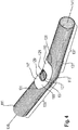
- Fig. 4 shows an inventive cantilever guide element with a discharge line.
- the cantilevered guide element 115 is attached to a discharge line 111, which comprises a bend 113.
- the discharge pipe 111 includes a first pipe portion 135 which is in contact with the first guide portion 117 of the cantilevered guide member 115.
- the discharge pipe 111 includes a second pipe portion 137 which is in contact with the second guide portion 119 of the cantilevered guide member 115, the first guide portion 117 extending from the second guide portion 119 in FIG Fig. 4 is separated by a dividing line 121.
- the cantilevered guide element 115 further comprises a recess 127, which is surrounded by an elevation 129, wherein the elevation 129 is circumferentially attached to the recess 127.
- the cantilever guide member 115 further includes at least one rounded boundary edge 131, which ensures the attachment of the cantilevered guide member 115 to the discharge line 111.
- the longitudinal axis 139 of the first line section 135 of the discharge line 111 encloses a bending angle with the longitudinal axis 141 of the second line section 137, so that it becomes clear that the cantilevered guide element 115 can be formed geometrically such that the cantilevered guide element 115 the discharge line 111 in the bending angle can bend.
- the advantage of the cantilevered guide element 115 according to the invention in comparison to conventional tube constructions is that the discharge line 111, which is arranged on the laundry care device 100, holds the discharge line 111 in one desired direction bent, can be dispensed with. In addition, it is also not necessary to use a mold line in which the desired direction is predetermined by the discharge line 111 itself.
- the self-supporting guide element 115 thus enables a defined laying of the discharge line 111 without the use of additional holders positioned on the laundry care device 100 for the discharge line 111.
- the self-supporting guide element 115 ensures repeatability of the laying line 111 being laid.
- the self-supporting guide element 115 also offers the simplest design of the assembly for the assembly processes and thus offers the most cost-effective solution.
Landscapes
- Engineering & Computer Science (AREA)
- Textile Engineering (AREA)
- Detail Structures Of Washing Machines And Dryers (AREA)
- Sink And Installation For Waste Water (AREA)
- Accessory Of Washing/Drying Machine, Commercial Washing/Drying Machine, Other Washing/Drying Machine (AREA)
Description
- Die vorliegende Erfindung betrifft ein Wäschepflegegerät mit einer Abführleitung.
- Bei der Verlegung von einer Abführleitung in einem Wäschepflegegerät wird die Verlegbarkeit der Abführleitung durch den begrenzten Bauraum in dem Wäschepflegegerät eingeschränkt. In dem Innenraum des Wäschepflegegeräts können verschiedene Elemente, wie z.B. Waschtrommel, Trocknertrommel, Schwingelemente, elektronische Baugruppen, Verkabelung, angeordnet sein. Insbesondere bei einem Wäschepflegegerät mit einem großen Füllvolumen wird eine kollisionsfreie Verlegung der Abführleitung im Innenraum des Wäschepflegegeräts durch vorhandene Elemente eingeschränkt.
-
JP 2012 254107 A - In
DE 41 26 771 A1 sind Wasserleitungsbauteile mit einem Wellrohr-Knickschlauch offenbart. - Die Patentschrift
US 5,311,753 zeigt einen Ablaufschlauch einer Waschmaschine. - Die Offenlegungsschrift
DE 10 2006 030 014 A1 zeigt eine Waschmaschine. - Es ist die Aufgabe der vorliegenden Erfindung, ein Wäschepflegegerät mit einer Abführleitung anzugeben, welche einen definierten Richtungsverlauf aufweist.
- Diese Aufgabe wird durch einen Gegenstand mit den Merkmalen nach dem unabhängigen Anspruch gelöst. Vorteilhafte Ausführungsformen sind Gegenstand der abhängigen Ansprüche, der Beschreibung und der Zeichnungen.
- Gemäß einem Aspekt wird die erfindungsgemäße Aufgabe durch ein Wäschepflegegerät mit einem Laugenbehälter und einer Abführleitung zum Abführen von Waschlauge aus dem Laugenbehälter, wobei die Abführleitung einen ersten Leitungsabschnitt und einen zweiten Leitungsabschnitt umfasst, gelöst, wobei das Wäschepflegegerät ein freitragendes Führungselement zum Führen der Abführleitung umfasst, wobei das freitragende Führungselement einen ersten Führungsabschnitt, welcher in Kontakt mit dem ersten Leitungsabschnitt steht, und einen zweiten Führungsabschnitt, welcher in Kontakt mit dem zweiten Leitungsabschnitt steht, umfasst, wobei der erste Führungsabschnitt und der zweite Führungsabschnitt starr verbunden sind, und wobei das freitragende Führungselement ausgebildet ist, den ersten Leitungsabschnitt gegenüber einer Längsachse des zweiten Leitungsabschnitts gebogen zu halten.
- Dadurch wird der technische Vorteil erreicht, dass durch das freitragende Führungselement die Abführleitung gebogen gehalten werden kann und somit die Abführleitung mit einem definierten Richtungsverlauf in dem Wäschepflegegerät verlegbar ist. Dies ist insbesondere dann von Vorteil, wenn für Verlegung der Abführleitung in dem Innenraum des Wäschepflegegeräts nur ein begrenzter Bauraum zu Verfügung steht und die Abführleitung deshalb gebogen gehalten werden muss, um an den in dem Innenraum des Wäschepflegegeräts vorhandenen Elementen vorbei verlegt zu werden. Bei bestimmten Elementen des Wäschepflegegeräts, wie z.B. Heizeinrichtungen, ist es insbesondere wichtig, dass die Abführleitung nicht mit diesen Elementen in Kontakt kommt, da die Abführleitung ansonsten beschädigt werden kann.
- Ein weiterer Vorteil des erfindungsgemäßen Führungselements ist, dass es als freitragendes Führungselement ausgebildet ist, welches die Abführleitung gebogen halten kann, ohne dass weitere Befestigungselemente an dem freitragenden Führungselement benötigt werden, um beispielsweise das freitragende Führungselement an dem Grundkörper des Wäschepflegegeräts zu befestigen. Dies ist insbesondere von Vorteil, wenn die Abführleitung im Innenraum des Wäschepflegegeräts geführt werden soll, und somit keine Möglichkeit besteht das freitragende Führungselement durch Befestigungselemente an dem Grundkörper des Wäschepflegegeräts zu befestigen.
- Die freitragenden Eigenschaften des freitragenden Führungselements werden durch die starre Verbindung des ersten Führungsabschnitts und des zweiten Führungsabschnitts in dem freitragenden Führungselement erreicht. Dadurch, dass der erste Führungsabschnitt in Kontakt mit dem ersten Leitungsabschnitt der Abführleitung steht, und dadurch, dass der zweite Führungsabschnitt in Kontakt mit dem zweiten Leitungsabschnitt der Abführleitung steht, kann der erste Leitungsabschnitt der Abführleitung nicht gegenüber dem zweiten Leitungsabschnitt bewegt werden. Dadurch wird der erste Leitungsabschnitt gegenüber der Längsachse des zweiten Leitungsabschnitts durch das freitragende Führungselement in einem bestimmten Biegewinkel gebogen gehalten. Somit bleibt die Steifigkeit der Abführleitung durch das freitragende Führungselement erhalten und das freitragende Führungselement kann die Abführleitung frei tragen, ohne dass weitere Befestigungselemente verwendet werden müssen.
- Somit ist das freitragende Führungselement geeignet, die erforderliche Steifigkeit des Abführschlauchs zu erhalten und eine ortsfeste Anbringung des Abführschlauchs mit einem definierten Richtungsverlauf bei Sicherung einer stabilen Lage zu gewährleisten.
- Dadurch, dass der erste Führungsabschnitt und der zweite Führungsabschnitt starr verbunden sind, wird insbesondere bewirkt, dass der erste Führungsabschnitt und der zweite Führungsabschnitt nicht gegeneinander bewegt werden können.
- Unter einem Wäschepflegegerät wird ein Gerät verstanden, welches zur Wäschepflege eingesetzt wird, wie z.B. eine Waschmaschine oder ein Wäschetrockner. Insbesondere wird unter solch einem Wäschepflegegerät ein Haushaltswäschepflegegerät verstanden. Also ein Wäschepflegegerät, welches im Rahmen der Haushaltsführung verwendet wird, und mit dem Wäsche in haushaltsüblichen Mengen behandelt wird.
- In einer vorteilhaften Ausführungsform des Wäschepflegegeräts umfasst die Abführleitung einen Kunststoff, insbesondere Polyethylen, Polyamid, Polypropylen, Polytetrafluorethylen, Polyvinylchlorid oder Mischungen davon.
- Dadurch wird der technische Vorteil erreicht, dass durch die Verwendung von Kunststoff eine leichte, formstabile, einfach zu bearbeitende und kostengünstige Abführleitung bereitgestellt werden kann. Polypropylen hat sich als besonders vorteilhafter Kunststoff für die Fertigung einer Abführleitung erwiesen, da Polypropylen eine vorteilhafte Steifigkeit, Härte und Festigkeit aufweist.
- In einer vorteilhaften Ausführungsform des Wäschepflegegeräts ist die Abführleitung als ein Wellrohr oder Wellschlauch ausgebildet.
- Dadurch wird der technische Vorteil erreicht, dass ein Wellrohr oder ein Wellschlauch eine flexible Abführleitung bereitstellt, die durch das freitragende Führungselement wirksam gebogen gehalten werden kann. Somit kann das Wellrohr, bzw. der Wellschlauch, wirksam in dem Innenraum des Wäschepflegegeräts verlegt werden.
- In einer vorteilhaften Ausführungsform des Wäschepflegegeräts umfasst das Wellrohr oder der Wellschlauch an der Außenfläche parallele ringförmige Ausformungen oder spiralförmige Ausformungen.
- Dadurch wird der technische Vorteil erreicht, dass durch die parallelen ringförmigen oder spiralförmigen Ausformungen an der Außenfläche, das Wellrohr oder der Wellschlauch eine ausreichende Flexibilität aufweist. Somit kann das Wellrohr oder der Wellschlauch wirksam gebogen gehalten werden ohne dass es zu Beschädigungen des Wellrohrs, bzw. des Wellschlauchs, kommt.
- In einer vorteilhaften Ausführungsform des Wäschepflegegeräts umfasst das freitragende Führungselement eine radiale Positionierrippe, wobei die radiale Positionierrippe in die parallelen ringförmigen Ausformungen oder in die spiralförmigen Ausformungen einführbar ist, um das freitragende Führungselement an dem Wellrohr oder an dem Wellschlauch zu positionieren.
- Dadurch wird der technische Vorteil erreicht, dass durch die Einführung der radialen Positionierrippe des freitragenden Führungselements in die Ausformungen des Wellrohrs oder des Wellschlauchs eine stabile Positionierung des freitragenden Führungselements an der Abführleitung sichergestellt werden kann. Dadurch, dass die radiale Positionierrippe in die Ausformungen eingreift kann das freitragende Führungselement nicht entlang der Längsachse der Abführleitung verschoben werden. Somit wird sichergestellt, dass der erste Führungsabschnitt in Kontakt mit dem ersten Leitungsabschnitt der Abführleitung steht, und dass der zweite Führungsabschnitt in Kontakt mit dem zweiten Leitungsabschnitt der Abführleitung steht und somit der erste Leitungsabschnitt gegenüber der Längsachse des zweiten Leitungsabschnitts gebogen gehalten wird.
- In einer vorteilhaften Ausführungsform des Wäschepflegegeräts ist das freitragende Führungselement mit der Abführleitung formschlüssig oder kraftschlüssig, insbesondere formschlüssig, verbunden.
- Dadurch wird der technische Vorteil erreicht, dass durch die formschlüssige oder kraftschlüssige Verbindung zwischen dem freitragenden Führungselement und der Abführleitung eine besonders stabile Befestigung erreicht wird.
- In einer vorteilhaften Ausführungsform des Wäschepflegegeräts umfasst das freitragende Führungselement einen Kunststoff, insbesondere Polyethylen, Polyamid, Polypropylen, Polytetrafluorethylen, Polyvinylchlorid oder Mischungen davon.
- Dadurch wird der technische Vorteil erreicht, dass sich durch die Verwendung von Kunststoff ein leichtes, formstabiles, einfach zu bearbeitendes, stabiles und kostengünstiges freitragendes Führungselement bereitstellen lässt. Polypropylen hat sich als besonders vorteilhafter Kunststoff für die Fertigung des freitragenden Führungselements erwiesen, da Polypropylen eine vorteilhafte Steifigkeit, Härte und Festigkeit aufweist.
- Erfindungsgemäß umfasst die Abführleitung des Wäschepflegegeräts einen Aufnahmebereich, umfasst das freitragende Führungselement eine axiale Positionierrippe, und ist die axiale Positionierrippe in den Aufnahmebereich einführbar, um das freitragende Führungselement an der Abführleitung zu positionieren.
- Dadurch wird der technische Vorteil erreicht, dass durch die Einführung der axialen Positionierrippe des freitragenden Führungselements in den Aufnahmebereich der Abführleitung eine stabile Positionierung des freitragenden Führungselements an der Abführleitung sichergestellt wird. Dadurch, dass die axiale Positionierrippe in den Aufnahmebereich eingreift, kann das freitragende Führungselement nicht an der Oberfläche der Abführleitung in radialer Richtung bewegt werden. Dadurch kann das freitragende Führungselement an der Abführleitung nicht verrutschen und die Abführleitung kann nicht verdreht werden. Somit wird eine stabile Befestigung des freitragenden Führungselements an der Abführleitung sichergestellt.
- In einer vorteilhaften Ausführungsform des Wäschepflegegeräts umfasst das freitragende Führungselement eine Aussparung zur Kontrolle der Abführleitung.
- Dadurch wird der technische Vorteil erreicht, dass der Nutzer durch die Aussparung in dem freitragenden Führungselement die Oberfläche der in gebogenem Zustand gehaltenen Abführleitung kontrollieren und gegebenenfalls auf Beschädigungen überprüfen kann. Darüber hinaus kann an der Abführleitung eine Markierung angebracht sein. Somit kann der Monteur des Wäschepflegegeräts durch die Aussparung die Markierung an der Oberfläche der Abführleitung erkennen, was eine präzise Positionierung des freitragenden Führungselements an der Abführleitung ermöglicht.
- In einer vorteilhaften Ausführungsform des Wäschepflegegeräts umfasst das freitragende Führungselement eine Erhöhung, wobei die Erhöhung umlaufend an der Aussparung angebracht ist.
- Dadurch wird der technische Vorteil erreicht, dass durch die Erhöhung, welche umlaufend an der Aussparung des freitragenden Führungselements angebracht ist, die Stabilität des freitragenden Führungselements im Bereich der Aussparung optimiert werden kann.
- In einer vorteilhaften Ausführungsform des Wäschepflegegeräts umfasst das freitragende Führungselement einen abgerundeten Begrenzungsrand, insbesondere mehrere abgerundete Begrenzungsränder.
- Dadurch wird der technische Vorteil erreicht, dass durch den abgerundeten Begrenzungsrand das freitragende Führungselement bei der Montage vorteilhaft an die Abführleitung angebracht werden kann. Hierbei kann die Abführleitung insbesondere an dem abgerundeten Begrenzungsrand vorbei durch das freitragende Führungselement geführt werden.
- In einer vorteilhaften Ausführungsform des Wäschepflegegeräts umfasst das freitragende Führungselement einen Hohlraum zur Aufnahme der Abführleitung.
- Dadurch wird der technische Vorteil erreicht, dass der Hohlraum derart ausgebildet ist, dass er die Abführleitung wirksam aufnehmen kann und somit das freitragende Führungselement die Abführleitung in einem gebogenen Zustand halten kann.
- In einer vorteilhaften Ausführungsform des Wäschepflegegeräts schließt die Längsachse des ersten Leitungsabschnitts gegenüber der Längsachse des zweiten Leitungsabschnitts einen Biegewinkel, insbesondere einen Biegewinkel zwischen 1° und 179°, ein.
- Dadurch wird der technische Vorteil erreicht, dass das freitragende Führungselement derart geometrisch ausgebildet werden kann, dass es die Abführleitung in einem spezifischen Biegewinkel halten kann. Je nach Ausgestaltung des freitragenden Führungselements ist kann ein großer Bereich des Biegewinkels abgedeckt werden. Ein Biegewinkel von 180° entspricht einer geraden Abführleitung. Das freitragende Führungselement kann die Abführleitung nur in einem minimal gebogenen Zustand halten, was einem Biegewinkel von etwa 179° entspricht. Das freitragende Führungselement kann die Abführleitung auch in einem stark gebogenen Zustand halten, so dass die Abführleitung eine Kehre bildet, was einem Biegewinkel von etwa 1° entspricht. Das freitragende Führungselement kann ferner die Abführleitung in beliebigen Biegewinkeln zwischen 1° und 179° gebogen halten.
- In einer vorteilhaften Ausführungsform des Wäschepflegegeräts umfasst das freitragende Führungselement ein Halterungselement, wobei das Halterungselement ausgebildet ist ein Element des Wäschepflegegeräts aufzunehmen.
- Dadurch wird der technische Vorteil erreicht, dass durch das Halterungselement, ein weiteres Element des Wäschepflegegeräts an dem freitragenden Führungselement befestigt werden kann. Dies kann insbesondere von Vorteil sein, wenn in der Nähe des Führungselements weitere Elemente des Wäschepflegegeräts angeordnet sind. Da das freitragende Führungselement freitragend und ohne eine Halterung stabil an der Abführleistung befestigt ist, kann das freitragende Führungselement selbst als Befestigungsanker für weitere Elemente des Wäschepflegegeräts fungieren.
- In einer vorteilhaften Ausführungsform des Wäschepflegegeräts umfasst das Element des Wäschepflegegeräts eine Leitung zum Leiten von elektrischer Energie.
- Dadurch wird der technische Vorteil erreicht, dass durch das Halterungselement eine elektrische Leitung an dem freitragenden Führungselement befestigt werden kann, wodurch das freitragende Führungselement aufgrund seiner intrinsischen Stabilität an der Abführleitung selbst als Haltung dienen kann.
- Nach einer Ausführungsform umfasst der erste Führungsabschnitt eine bezogen auf seine Längsachse seitliche erste Öffnung zum Einführen der Abführleitung. Das heißt also insbesondere, dass der erste Führungsabschnitt nicht in sich geschlossen ausgebildet ist. Das heißt also insbesondere, dass der erste Führungsabschnitt bezogen auf seine Längsachse seitlich offen ist.
- Dadurch wird insbesondere der technische Vorteil bewirkt, dass die Abführleitung bei der Montage effizient in den ersten Führungsabschnitt eingeführt werden kann.
- Der erste Führungsabschnitt ist insbesondere federelastisch ausgebildet, so dass die erste Öffnung in ihrer Größe geändert werden kann. Das heißt also insbesondere, dass durch ein Zusammendrücken des ersten Führungsabschnitts die Größe der ersten Öffnung reduziert wird. Das heißt also insbesondere, dass die erste Öffnung aufgrund der Federelastizität aufgeweitet werden kann. Dadurch kann die Abführleitung effizient in den ersten Führungsabschnitt eingeführt werden. Dies insbesondere dadurch, dass die erste Öffnung aufgeweitet wird, dann die Abführleitung in den ersten Führungsabschnitt eingeführt wird, wobei dann das Aufweiten beendet wird, so dass die erste Öffnung wieder ihre ursprüngliche Größe bekommt.
- Die erste Öffnung ist zum Beispiel durch einen oder mehrere abgerundete Begrenzungsränder begrenzt.
- Nach einer Ausführungsform umfasst der zweite Führungsabschnitt eine bezogen auf seine Längsachse seitliche zweite Öffnung zum Einführen der Abführleitung. Das heißt also insbesondere, dass der zweite Führungsabschnitt nicht in sich geschlossen ausgebildet ist. Das heißt also insbesondere, dass der zweite Führungsabschnitt bezogen auf seine Längsachse seitlich offen ist.
- Dadurch wird insbesondere der technische Vorteil bewirkt, dass die Abführleitung bei der Montage effizient in den zweiten Führungsabschnitt eingeführt werden kann.
- Der zweite Führungsabschnitt ist insbesondere federelastisch ausgebildet, so dass die zweite Öffnung in ihrer Größe geändert werden kann. Das heißt also insbesondere, dass durch ein Zusammendrücken des zweiten Führungsabschnitts die Größe der zweiten Öffnung reduziert wird. Das heißt also insbesondere, dass die zweite Öffnung aufgrund der Federelastizität aufgeweitet werden kann. Dadurch kann die Abführleitung effizient in den zweiten Führungsabschnitt eingeführt werden. Dies insbesondere dadurch, dass die zweite Öffnung aufgeweitet wird, dann die Abführleitung in den zweiten Führungsabschnitt eingeführt wird, wobei dann das Aufweiten beendet wird, so dass die zweite Öffnung wieder ihre ursprüngliche Größe erhält.
- Die zweite Öffnung ist zum Beispiel durch einen oder mehrere abgerundete Begrenzungsränder begrenzt.
- Nach einer Ausführungsform geht die seitliche erste Öffnung in die seitliche zweite Öffnung über, so dass eine durchgehende Öffnung gebildet ist. Diese durchgehende Öffnung verläuft also insbesondere von dem ersten Führungsabschnitt zu dem zweiten Führungsabschnitt.
- Dadurch wird insbesondere der technische Vorteil bewirkt, dass die Abführleitung bei der Montage effizient in das Führungselement eingeführt werden kann.
- Die durchgehende Öffnung kann bei einer federelastischen Ausbildung des ersten und des zweiten Führungsabschnitts analog zur ersten und zweiten Öffnung aufgeweitet oder zusammengedrückt werden. Auf die entsprechend gemachten Ausführungen wird verwiesen. Zum Einführen der Abführleitung wird die durchgehende Öffnung aufgeweitet, dann wird die Abführleitung in den ersten und in den zweiten Führungsabschnitt eingeführt, wobei dann das Aufweiten beendet wird, so dass die durchgehende Öffnung wieder ihre ursprüngliche Größe erhält.
- Die durchgehende Öffnung ist zum Beispiel durch einen oder mehrere abgerundete Begrenzungsränder begrenzt.
- In einer Ausführungsform ist der Hohlraum relativ zu einer Längsachse des ersten Leitungsabschnitts und/oder relativ zu einer Längsachse des zweiten Leitungsabschnitts seitlich offen. Zum Beispiel ist die seitliche Öffnung des Hohlraums mittels der ersten und/oder mittels der zweiten Öffnung gebildet. Die seitliche Öffnung des Hohlraums ist zum Beispiel mittels der durchgehenden Öffnung gebildet.
- Weitere Ausführungsbeispiele werden Bezug nehmend auf die beiliegenden Zeichnungen erläutert. Es zeigen:
- Fig. 1
- eine schematische Ansicht eines Wäschepflegegeräts;
- Fig. 2
- eine schematische Ansicht eines Wäschepflegegeräts mit einem Laugenbehälter und einer Abführleitung;
- Fig. 3
- ein erfindungsgemäßes freitragendes Führungselement; und
- Fig. 4
- ein erfindungsgemäßes freitragendes Führungselement an einer Abführleitung.
-
Fig. 1 zeigt eine schematische Ansicht eines allgemeinen Wäschepflegegeräts 100, wie z.B. eine Waschmaschine. Das Wäschepflegegerät 100 umfasst einen Vorratsbehälter 101, der auch als Einspülschale bezeichnet wird, und in den Waschmittel oder andere flüssige Substanzen eingefüllt werden können. Das Wäschepflegegerät 100 umfasst eine Tür 103 zum Beladen des Wäschepflegegerätes 100 mit Wäsche. -
Fig. 2 zeigt eine Innenansicht des Wäschepflegegerätes 100 mit einem Laugenbehälter 105 zur Aufnahme von Waschlauge und mit einer Waschtrommel 107 zur Aufnahme von Wäsche. Der Laugenbehälter 105 umfasst eine Abführöffnung 109, durch welche die Waschlauge nach Beendigung des Waschgangs aus dem Laugenbehälter 105 abfließen kann. Die Abführöffnung 109 ist mit einer Abführleitung 111 verbunden durch welche die aus dem Laugenbehälter 105 abfließende Waschlauge aus dem Wäschepflegegerät 100 abgeleitet werden kann. Die Abführleitung 111 umfasst eine oder mehrere Biegungen 113. Bei einer engen Bauraumsituation in Wäschepflegegeräten 100 ist es entscheidend, dass der zur Verfügung stehende Bauraum effizient genutzt wird. Durch die Verwendung einer Abführleitung 111 mit einer oder mehrere Biegungen 113 kann die Abführleitung 111 flexibel in dem Innenraum des Wäschepflegegeräts 100 verlegt werden und kann insbesondere an anderen Elementen vorbeigeführt werden. -
Fig. 3 zeigt ein erfindungsgemäßes freitragendes Führungselement. Um eine Biegung einer Abführleitung sicherzustellen umfasst die Abführleitung ein freitragendes Führungselement 115. - Das freitragende Führungselement 115 umfasst einen ersten Führungsabschnitt 117 und einen zweiten Führungsabschnitt 119, wobei die beiden Abschnitte in
Fig. 3 durch eine Trennlinie 121 voneinander getrennt sind. Der erste Führungsabschnitt 117 und der zweite Führungsabschnitt 119 sind in dem freitragenden Führungselement 115 starr miteinander verbunden, und können gegeneinander nicht bewegt werden. Der erste Führungsabschnitt 117 steht in Kontakt mit einem ersten Leitungsabschnitt der Abführleitung und der zweite Führungsabschnitt 119 steht in Kontakt mit einem zweiten Leitungsabschnitt der Abführleitung, wodurch eine starre und stabile Führung des ersten und des zweiten Leitungsabschnitts in der Abführleitung sichergestellt wird. Der erste und zweite Leitungsabschnitt der Abführleitung sind inFig. 3 nicht dargestellt. - Das freitragende Führungselement 115 kann eine radiale Positionierrippe 123 umfassen. Bei der Verwendung von einem Wellrohr oder Wellschlauch mit parallelen ringförmigen oder spiralförmigen Ausformungen als Abführleitung ist die radiale Positionierrippe 123 in die Ausformungen einführbar, um das freitragende Führungselement 115 wirksam an der Oberfläche der Abführleitung zu positionieren. Dadurch kann das freitragende Führungselement 115 nicht entlang der Längsachse der Abführleitung verschoben werden.
- Das freitragende Führungselement 115 kann eine axiale Positionierrippe 125 umfassen. Wenn die Abführleitung einen Aufnahmebereich aufweist, kann die axiale Positionierrippe 125 in den Aufnahmebereich eingeführt werden, um das freitragende Führungselement 115 an der Abführleitung zu positionieren. Dadurch kann das freitragende Führungselement 115 nicht an der Oberfläche der Abführleitung in radialer Richtung bewegt werden und kann somit nicht an der Oberfläche der Abführleitung verrutschen. Das freitragende Führungselement 115 umfasst ferner eine Aussparung 127, welche von einer Erhöhung 129 umgeben ist, wobei die Erhöhung 129 umlaufend an der Aussparung 127 angebracht ist. Das freitragende Führungselement 115 umfasst ferner einen abgerundeten Begrenzungsrand 131, welcher das Anbringen des freitragenden Führungselements 115 an der Abführleitung sicherstellt. Das freitragende Führungselement 115 kann mehrere abgerundete Begrenzungsränder 131 umfassen, welche das Einführen der Abführleitung in das freitragende Führungselement 115 erleichtern. Das freitragende Führungselement 115 umfasst ferner einen Hohlraum 133 zur Aufnahme der Abführleitung.
-
Fig. 4 zeigt ein erfindungsgemäßes freitragendes Führungselement mit einer Abführleitung. Das freitragende Führungselement 115 ist an einer Abführleitung 111 befestigt, welche eine Biegung 113 umfasst. Die Abführleitung 111 umfasst einen ersten Leitungsabschnitt 135 welcher mit dem ersten Führungsabschnitt 117 des freitragenden Führungselements 115 in Kontakt steht. Die Abführleitung 111 umfasst einen zweiten Leitungsabschnitt 137 welcher mit dem zweiten Führungsabschnitt 119 des freitragenden Führungselements 115 in Kontakt steht, wobei der erste Führungsabschnitt 117 von dem zweiten Führungsabschnitt 119 inFig. 4 durch eine Trennlinie 121 getrennt ist. - Das freitragende Führungselement 115 umfasst ferner eine Aussparung 127, welche von einer Erhöhung 129 umgeben ist, wobei die Erhöhung 129 umlaufend an der Aussparung 127 angebracht ist. Das freitragende Führungselement 115 umfasst ferner zumindest einen abgerundeten Begrenzungsrand 131, welcher das Anbringen des freitragenden Führungselements 115 an der Abführleitung 111 sicherstellt.
- Die Längsachse 139 des ersten Leitungsabschnitts 135 der Abführleitung 111 schließt mit der Längsachse 141 des zweiten Leitungsabschnitts 137 einen Biegewinkel ein, so dass deutlich wird, dass das freitragende Führungselement 115 derart geometrisch ausgebildet werden kann, dass das freitragende Führungselement 115 die Abführleitung 111 in dem Biegewinkel gebogen halten kann.
- Der Vorteil des erfindungsgemäßen freitragenden Führungselements 115 gegenüber herkömmlichen Schlauchkonstruktionen ist, dass auf eine an dem Wäschepflegegerät 100 angeordnete Halterung der Abführleitung 111, welche die Abführleitung 111 in einer gewünschte Richtung gebogen hält, verzichtet werden kann. Zudem ist es auch nicht nötigt, eine Formleitung zu verwenden, bei der die gewünschte Richtung durch die Abführleitung 111 selbst vorgegeben wird.
- Das erfindungsgemäße freitragende Führungselement 115 ermöglicht somit eine definierte Verlegung der Abführleitung 111 ohne die Verwendung von zusätzlichen an dem Wäschepflegegerät 100 positionierten Halterungen für die Abführleitung 111. Durch das freitragende Führungselement 115 wird eine Wiederholbarkeit des Verlegens der Abführleitung 111 gesichert. Das freitragende Führungselement 115 bietet zudem die einfachste Ausführung der Baueinheit für die Montageprozesse und bietet damit die kostengünstigste Lösung.
- Alle in Verbindung mit einzelnen Ausführungsformen der Erfindung erläuterten und gezeigten Merkmale können in unterschiedlicher Kombination in dem erfindungsgemäßen Gegenstand vorgesehen sein, um gleichzeitig deren vorteilhafte Wirkungen zu realisieren.
- Der Schutzbereich der vorliegenden Erfindung ist durch die Ansprüche gegeben und wird durch die in der Beschreibung erläuterten oder den Figuren gezeigten Merkmale nicht beschränkt.
-
- 100
- Wäschepflegegerät
- 101
- Vorratsbehälter
- 103
- Gerätetür
- 105
- Laugenbehälter
- 107
- Waschtrommel
- 109
- Abführöffnung
- 111
- Abführleitung
- 113
- Biegung
- 115
- Freitragendes Führungselement
- 117
- Erster Führungsabschnitt
- 119
- Zweiter Führungsabschnitt
- 121
- Trennlinie
- 123
- Radiale Positionierrippe
- 125
- Axiale Positionierrippe
- 127
- Aussparung
- 129
- Erhöhung
- 131
- Abgerundeter Begrenzungsrand
- 133
- Hohlraum
- 135
- Erster Leitungsabschnitt
- 137
- Zweiter Leitungsabschnitt
- 139
- Längsachse des ersten Leitungsabschnitts
- 141
- Längsachse des zweiten Leitungsabschnitts
Claims (14)
- Wäschepflegegerät (100) mit einem Laugenbehälter (105) und einer in einem Innenraum des Wäschepflegegeräts (100) verlegten Abführleitung (111) zum Abführen von Waschlauge aus dem Laugenbehälter (105), wobei die Abführleitung (111) einen ersten Leitungsabschnitt (135) und einen zweiten Leitungsabschnitt (137) umfasst, wobei
das Wäschepflegegerät (100) ein freitragendes Führungselement (115) zum Führen der Abführleitung (111) umfasst,
das freitragende Führungselement (115) einen ersten Führungsabschnitt (117), welcher in Kontakt mit dem ersten Leitungsabschnitt (135) steht, und einen zweiten Führungsabschnitt (119), welcher in Kontakt mit dem zweiten Leitungsabschnitt (137) steht, umfasst, wobei
der erste Führungsabschnitt (117) und der zweite Führungsabschnitt (119) starr verbunden sind, wodurch bewirkt wird, dass der erste Führungsabschnitt (117) und der zweite Führungsabschnitt (119) nicht gegeneinander bewegt werden können, und
das freitragende Führungselement (115) ausgebildet ist, den ersten Leitungsabschnitt (135) gegenüber der Längsachse (141) des zweiten Leitungsabschnitts (137) gebogen zu halten,
sodass durch das freitragende Führungselement (115) die Abführleitung (111) gebogen gehalten werden kann und somit die Abführleitung (111) mit einem definierten Richtungsverlauf in dem Innenraum des Wäschepflegegeräts (100) verlegbar ist,
wobei die Abführleitung (111) eine Biegung (113) umfasst, die mittels des freitragenden Führungselements (115) sichergestellt ist, und dadurch gekennzeichnet, dass die Abführleitung (111) einen Aufnahmebereich umfasst, dass das freitragende Führungselement (115) eine axiale Positionierrippe (125) umfasst, und dass die axiale Positionierrippe (125) in den Aufnahmebereich einführbar ist, um das freitragende Führungselement (115) an der Abführleitung (111) zu positionieren. - Wäschepflegegerät (100) nach Anspruch 1, dadurch gekennzeichnet, dass die Abführleitung (111) einen Kunststoff, insbesondere Polyethylen, Polyamid, Polypropylen, Polytetrafluorethylen, Polyvinylchlorid oder Mischungen davon, umfasst.
- Wäschepflegegerät (100) nach Anspruch 2, dadurch gekennzeichnet, dass die Abführleitung (111) als ein Wellrohr oder Wellschlauch ausgebildet ist.
- Wäschepflegegerät (100) nach Anspruch 3, dadurch gekennzeichnet, dass das Wellrohr oder der Wellschlauch an der Außenfläche parallele ringförmige Ausformungen oder spiralförmige Ausformungen umfasst.
- Wäschepflegegerät (100) nach Anspruch 4, dadurch gekennzeichnet, dass das freitragende Führungselement (115) eine radiale Positionierrippe (123) umfasst, dass die radiale Positionierrippe (123) in die parallelen ringförmigen Ausformungen oder in die spiralförmigen Ausformungen einführbar ist, um das freitragende Führungselement (115) an dem Wellrohr oder an dem Wellschlauch zu positionieren.
- Wäschepflegegerät (100) nach einem der vorangehenden Ansprüche, dadurch gekennzeichnet, dass das freitragende Führungselement (115) mit der Abführleitung (111) formschlüssig oder kraftschlüssig, insbesondere formschlüssig, verbunden ist.
- Wäschepflegegerät (100) nach einem der vorangehenden Ansprüche, dadurch gekennzeichnet, dass das freitragende Führungselement (115) einen Kunststoff, insbesondere Polyethylen, Polyamid, Polypropylen, Polytetrafluorethylen, Polyvinylchlorid oder Mischungen davon, umfasst.
- Wäschepflegegerät (100) nach einem der vorangehenden Ansprüche, dadurch gekennzeichnet, dass das freitragende Führungselement (115) eine Aussparung (127) zur Kontrolle der Abführleitung (111) umfasst.
- Wäschepflegegerät (100) nach Anspruch 8, dadurch gekennzeichnet, dass das freitragende Führungselement (115) eine Erhöhung (129) umfasst, wobei die Erhöhung (129) umlaufend an der Aussparung (127) angebracht ist.
- Wäschepflegegerät (100) nach einem der vorangehenden Ansprüche, dadurch gekennzeichnet, dass das freitragende Führungselement (115) einen abgerundeten Begrenzungsrand (131) umfasst.
- Wäschepflegegerät (100) nach einem der vorangehenden Ansprüche, dadurch gekennzeichnet, dass das freitragende Führungselement (115) einen Hohlraum (133) zur Aufnahme der Abführleitung (111) umfasst.
- Wäschepflegegerät (100) nach einem der vorangehenden Ansprüche, dadurch gekennzeichnet, dass die Längsachse (139) des ersten Leitungsabschnitts (135) gegenüber der Längsachse (141) des zweiten Leitungsabschnitts (137) einen Biegewinkel, insbesondere einen Biegewinkel zwischen 1° und 179°, einschließt.
- Wäschepflegegerät (100) nach einem der vorangehenden Ansprüche, dadurch gekennzeichnet, dass das freitragende Führungselement (115) ein Halterungselement umfasst, wobei das Halterungselement ausgebildet ist ein Element des Wäschepflegegeräts (100) aufzunehmen.
- Wäschepflegegerät (100) nach Anspruch 13, dadurch gekennzeichnet, dass das Element des Wäschepflegegerät (100) eine Leitung zum Leiten von elektrischer Energie umfasst.
Applications Claiming Priority (2)
| Application Number | Priority Date | Filing Date | Title |
|---|---|---|---|
| DE102015206312.7A DE102015206312A1 (de) | 2015-04-09 | 2015-04-09 | Wäschepflegegerät mit einer Abführleitung |
| PCT/EP2016/056749 WO2016162235A1 (de) | 2015-04-09 | 2016-03-29 | Wäschepflegegerät mit einer abführleitung |
Publications (2)
| Publication Number | Publication Date |
|---|---|
| EP3280838A1 EP3280838A1 (de) | 2018-02-14 |
| EP3280838B1 true EP3280838B1 (de) | 2019-05-22 |
Family
ID=55629042
Family Applications (1)
| Application Number | Title | Priority Date | Filing Date |
|---|---|---|---|
| EP16711851.2A Active EP3280838B1 (de) | 2015-04-09 | 2016-03-29 | Wäschepflegegerät mit einer abführleitung |
Country Status (4)
| Country | Link |
|---|---|
| EP (1) | EP3280838B1 (de) |
| CN (1) | CN107529935B (de) |
| DE (1) | DE102015206312A1 (de) |
| WO (1) | WO2016162235A1 (de) |
Families Citing this family (2)
| Publication number | Priority date | Publication date | Assignee | Title |
|---|---|---|---|---|
| KR102523465B1 (ko) | 2017-11-09 | 2023-04-18 | 엘지전자 주식회사 | 의류처리장치 |
| DE102018202534A1 (de) * | 2018-02-20 | 2019-08-22 | BSH Hausgeräte GmbH | Bauteil für ein Gerät zum Behandeln von Wäsche oder Geschirr sowie Verfahren zum Herstellen eines solchen Bauteils |
Family Cites Families (14)
| Publication number | Priority date | Publication date | Assignee | Title |
|---|---|---|---|---|
| US4151864A (en) * | 1975-03-31 | 1979-05-01 | Arundale, Inc. | Drain adapter for corrugated hose |
| JPH051486U (ja) * | 1991-06-19 | 1993-01-14 | 史朗 金尾 | 洗濯機用ホース |
| DE4126771A1 (de) | 1991-08-13 | 1993-02-18 | Bosch Siemens Hausgeraete | Wasserfuehrendes haushaltgeraet |
| DE29909715U1 (de) * | 1999-06-04 | 1999-09-02 | Anton Hummel Verwaltungs Gmbh, 79183 Waldkirch | Wellschlauch mit einer Halterung |
| US6311936B1 (en) * | 1999-07-30 | 2001-11-06 | Maytag Corporation | Hose retainer |
| US7549191B2 (en) * | 2004-11-22 | 2009-06-23 | Shop Vac Corporation | Gutter cleaning blower vacuum attachment apparatus |
| KR101165627B1 (ko) * | 2005-06-30 | 2012-07-17 | 엘지전자 주식회사 | 드럼세탁기의 배수호스 고정장치 |
| CN201007388Y (zh) * | 2006-07-26 | 2008-01-16 | 韩红军 | 全隐蔽式给水栓及配套使用的快速接头 |
| JP2008110088A (ja) * | 2006-10-31 | 2008-05-15 | Matsushita Electric Ind Co Ltd | ドラム式洗濯乾燥機 |
| DE102009008684B4 (de) * | 2009-02-06 | 2011-03-10 | Maico Elektroapparate-Fabrik Gmbh | Befestigungselement, Vorrichtung sowie Verfahren zum Befestigen eines flexiblen Rohres |
| CN201407420Y (zh) * | 2009-05-25 | 2010-02-17 | 李金生 | 软管固定装置 |
| JP3157888U (ja) * | 2009-12-18 | 2010-03-04 | 株式会社徳信洋行 | 給水システム |
| US20120255329A1 (en) * | 2011-04-06 | 2012-10-11 | Bsh Home Appliances Corporation | Drain hose for a washer |
| JP2012254107A (ja) * | 2011-06-07 | 2012-12-27 | Toshiba Corp | 洗濯機 |
-
2015
- 2015-04-09 DE DE102015206312.7A patent/DE102015206312A1/de not_active Withdrawn
-
2016
- 2016-03-29 WO PCT/EP2016/056749 patent/WO2016162235A1/de not_active Ceased
- 2016-03-29 EP EP16711851.2A patent/EP3280838B1/de active Active
- 2016-03-29 CN CN201680020733.9A patent/CN107529935B/zh not_active Expired - Fee Related
Non-Patent Citations (1)
| Title |
|---|
| None * |
Also Published As
| Publication number | Publication date |
|---|---|
| DE102015206312A1 (de) | 2016-10-13 |
| WO2016162235A1 (de) | 2016-10-13 |
| CN107529935A (zh) | 2018-01-02 |
| CN107529935B (zh) | 2020-03-13 |
| EP3280838A1 (de) | 2018-02-14 |
Similar Documents
| Publication | Publication Date | Title |
|---|---|---|
| DE102007027547B4 (de) | Waschmaschine | |
| DE102007060854A1 (de) | Reinigungsvorrichtung für ein mit Flusen beladenes Bauteil in einem Hausgerät sowie Hausgerät und Verfahren zum Reinigen eines mit Flusen beladenen Bauteils | |
| EP2106236B1 (de) | Korbführungsschiene für eine geschirrspülmaschine | |
| EP2145993B1 (de) | Manschette für eine Wäschebehandlungsmaschine und eine Wäschebehandlungsmaschine mit einer solchen Manschette | |
| WO2016162235A1 (de) | Wäschepflegegerät mit einer abführleitung | |
| DE112018001841B4 (de) | Waschmaschine | |
| EP1544344B1 (de) | Frontbeschickbare Waschmaschine und Verfahren zur Herstellung einer solchen Waschmaschine | |
| EP2794980B1 (de) | Laugenabpumpstrang für ein haushaltsgerät zur pflege von wäschestücken sowie entsprechendes haushaltsgerät mit einem laugenabpumpstrang | |
| EP2022882A2 (de) | Trommel für eine Waschmaschine und Waschmaschine | |
| DE19844568C1 (de) | Befestigungsvorrichtung für elektrische Rohrkörper von Trommelwaschmaschinen | |
| EP3282047B1 (de) | Haushaltsgerät mit einem türscharnier | |
| EP0915197B1 (de) | Wasserführende Haushaltmaschine | |
| EP2306880B1 (de) | Wasserführendes haushaltsgerät | |
| DE102009046682A1 (de) | Tür für ein Wäschebehandlungsgerät und Verfahren zum Herstellen einer solchen | |
| EP1669489B1 (de) | Kunststofflaugenbehälter für eine Waschmaschine mit angeformten Rippen | |
| EP3283681B1 (de) | Anordnung mit einer wäschetrommel und einer unwuchtausgleichsvorrichtung, haushaltsgerät zur pflege von wäschestücken und verfahren zum befestigen einer unwuchtausgleichsvorrichtung | |
| EP2101386B1 (de) | Elektrisches Haustechnikgerät | |
| EP2201886A1 (de) | Spülgutträger mit einem Anschlussstück für schlauchförmiges Reinigungsgut | |
| EP1609903B1 (de) | Vorrichtung zur Halterung eines Heizkörpers in Trommelwaschmaschinen | |
| DE112005000124B4 (de) | Geschirrspülmaschine und zugehörige Ablaufschlauch-Befestigungsanordnung | |
| DE102015104987B4 (de) | Haushaltsgerät | |
| EP1835064B1 (de) | Laugenbehälter mit plattenförmiger Heizeinrichtung | |
| DE102016200604B3 (de) | Wäschepflegegerät mit einem Klemmring | |
| DE102011120730A1 (de) | Befestigungsvorrichtung zum Verbinden eines Endoskopes mit einem Tubus | |
| DE102017209419B4 (de) | Haushaltsgerät mit einem Türscharnier |
Legal Events
| Date | Code | Title | Description |
|---|---|---|---|
| STAA | Information on the status of an ep patent application or granted ep patent |
Free format text: STATUS: THE INTERNATIONAL PUBLICATION HAS BEEN MADE |
|
| PUAI | Public reference made under article 153(3) epc to a published international application that has entered the european phase |
Free format text: ORIGINAL CODE: 0009012 |
|
| STAA | Information on the status of an ep patent application or granted ep patent |
Free format text: STATUS: REQUEST FOR EXAMINATION WAS MADE |
|
| 17P | Request for examination filed |
Effective date: 20171109 |
|
| AK | Designated contracting states |
Kind code of ref document: A1 Designated state(s): AL AT BE BG CH CY CZ DE DK EE ES FI FR GB GR HR HU IE IS IT LI LT LU LV MC MK MT NL NO PL PT RO RS SE SI SK SM TR |
|
| AX | Request for extension of the european patent |
Extension state: BA ME |
|
| RIN1 | Information on inventor provided before grant (corrected) |
Inventor name: PATEL, NECDET Inventor name: RICHTER, KURT Inventor name: XU, JINXIN Inventor name: MUENCH, OLAF |
|
| DAV | Request for validation of the european patent (deleted) | ||
| DAX | Request for extension of the european patent (deleted) | ||
| GRAP | Despatch of communication of intention to grant a patent |
Free format text: ORIGINAL CODE: EPIDOSNIGR1 |
|
| STAA | Information on the status of an ep patent application or granted ep patent |
Free format text: STATUS: GRANT OF PATENT IS INTENDED |
|
| INTG | Intention to grant announced |
Effective date: 20190111 |
|
| RIN1 | Information on inventor provided before grant (corrected) |
Inventor name: MUENCH, OLAF Inventor name: XU, JINXIN Inventor name: RICHTER, KURT Inventor name: PATEL, NECDET |
|
| GRAS | Grant fee paid |
Free format text: ORIGINAL CODE: EPIDOSNIGR3 |
|
| GRAA | (expected) grant |
Free format text: ORIGINAL CODE: 0009210 |
|
| STAA | Information on the status of an ep patent application or granted ep patent |
Free format text: STATUS: THE PATENT HAS BEEN GRANTED |
|
| AK | Designated contracting states |
Kind code of ref document: B1 Designated state(s): AL AT BE BG CH CY CZ DE DK EE ES FI FR GB GR HR HU IE IS IT LI LT LU LV MC MK MT NL NO PL PT RO RS SE SI SK SM TR |
|
| REG | Reference to a national code |
Ref country code: GB Ref legal event code: FG4D Free format text: NOT ENGLISH |
|
| REG | Reference to a national code |
Ref country code: CH Ref legal event code: EP |
|
| REG | Reference to a national code |
Ref country code: IE Ref legal event code: FG4D Free format text: LANGUAGE OF EP DOCUMENT: GERMAN |
|
| REG | Reference to a national code |
Ref country code: AT Ref legal event code: REF Ref document number: 1136245 Country of ref document: AT Kind code of ref document: T Effective date: 20190615 |
|
| REG | Reference to a national code |
Ref country code: DE Ref legal event code: R096 Ref document number: 502016004784 Country of ref document: DE |
|
| REG | Reference to a national code |
Ref country code: NL Ref legal event code: MP Effective date: 20190522 |
|
| REG | Reference to a national code |
Ref country code: LT Ref legal event code: MG4D |
|
| PG25 | Lapsed in a contracting state [announced via postgrant information from national office to epo] |
Ref country code: NL Free format text: LAPSE BECAUSE OF FAILURE TO SUBMIT A TRANSLATION OF THE DESCRIPTION OR TO PAY THE FEE WITHIN THE PRESCRIBED TIME-LIMIT Effective date: 20190522 Ref country code: SE Free format text: LAPSE BECAUSE OF FAILURE TO SUBMIT A TRANSLATION OF THE DESCRIPTION OR TO PAY THE FEE WITHIN THE PRESCRIBED TIME-LIMIT Effective date: 20190522 Ref country code: ES Free format text: LAPSE BECAUSE OF FAILURE TO SUBMIT A TRANSLATION OF THE DESCRIPTION OR TO PAY THE FEE WITHIN THE PRESCRIBED TIME-LIMIT Effective date: 20190522 Ref country code: LT Free format text: LAPSE BECAUSE OF FAILURE TO SUBMIT A TRANSLATION OF THE DESCRIPTION OR TO PAY THE FEE WITHIN THE PRESCRIBED TIME-LIMIT Effective date: 20190522 Ref country code: FI Free format text: LAPSE BECAUSE OF FAILURE TO SUBMIT A TRANSLATION OF THE DESCRIPTION OR TO PAY THE FEE WITHIN THE PRESCRIBED TIME-LIMIT Effective date: 20190522 Ref country code: PT Free format text: LAPSE BECAUSE OF FAILURE TO SUBMIT A TRANSLATION OF THE DESCRIPTION OR TO PAY THE FEE WITHIN THE PRESCRIBED TIME-LIMIT Effective date: 20190922 Ref country code: AL Free format text: LAPSE BECAUSE OF FAILURE TO SUBMIT A TRANSLATION OF THE DESCRIPTION OR TO PAY THE FEE WITHIN THE PRESCRIBED TIME-LIMIT Effective date: 20190522 Ref country code: HR Free format text: LAPSE BECAUSE OF FAILURE TO SUBMIT A TRANSLATION OF THE DESCRIPTION OR TO PAY THE FEE WITHIN THE PRESCRIBED TIME-LIMIT Effective date: 20190522 Ref country code: NO Free format text: LAPSE BECAUSE OF FAILURE TO SUBMIT A TRANSLATION OF THE DESCRIPTION OR TO PAY THE FEE WITHIN THE PRESCRIBED TIME-LIMIT Effective date: 20190822 |
|
| PG25 | Lapsed in a contracting state [announced via postgrant information from national office to epo] |
Ref country code: GR Free format text: LAPSE BECAUSE OF FAILURE TO SUBMIT A TRANSLATION OF THE DESCRIPTION OR TO PAY THE FEE WITHIN THE PRESCRIBED TIME-LIMIT Effective date: 20190823 Ref country code: LV Free format text: LAPSE BECAUSE OF FAILURE TO SUBMIT A TRANSLATION OF THE DESCRIPTION OR TO PAY THE FEE WITHIN THE PRESCRIBED TIME-LIMIT Effective date: 20190522 Ref country code: BG Free format text: LAPSE BECAUSE OF FAILURE TO SUBMIT A TRANSLATION OF THE DESCRIPTION OR TO PAY THE FEE WITHIN THE PRESCRIBED TIME-LIMIT Effective date: 20190822 Ref country code: RS Free format text: LAPSE BECAUSE OF FAILURE TO SUBMIT A TRANSLATION OF THE DESCRIPTION OR TO PAY THE FEE WITHIN THE PRESCRIBED TIME-LIMIT Effective date: 20190522 |
|
| PG25 | Lapsed in a contracting state [announced via postgrant information from national office to epo] |
Ref country code: DK Free format text: LAPSE BECAUSE OF FAILURE TO SUBMIT A TRANSLATION OF THE DESCRIPTION OR TO PAY THE FEE WITHIN THE PRESCRIBED TIME-LIMIT Effective date: 20190522 Ref country code: EE Free format text: LAPSE BECAUSE OF FAILURE TO SUBMIT A TRANSLATION OF THE DESCRIPTION OR TO PAY THE FEE WITHIN THE PRESCRIBED TIME-LIMIT Effective date: 20190522 Ref country code: RO Free format text: LAPSE BECAUSE OF FAILURE TO SUBMIT A TRANSLATION OF THE DESCRIPTION OR TO PAY THE FEE WITHIN THE PRESCRIBED TIME-LIMIT Effective date: 20190522 Ref country code: CZ Free format text: LAPSE BECAUSE OF FAILURE TO SUBMIT A TRANSLATION OF THE DESCRIPTION OR TO PAY THE FEE WITHIN THE PRESCRIBED TIME-LIMIT Effective date: 20190522 Ref country code: SK Free format text: LAPSE BECAUSE OF FAILURE TO SUBMIT A TRANSLATION OF THE DESCRIPTION OR TO PAY THE FEE WITHIN THE PRESCRIBED TIME-LIMIT Effective date: 20190522 |
|
| REG | Reference to a national code |
Ref country code: DE Ref legal event code: R097 Ref document number: 502016004784 Country of ref document: DE |
|
| PG25 | Lapsed in a contracting state [announced via postgrant information from national office to epo] |
Ref country code: SM Free format text: LAPSE BECAUSE OF FAILURE TO SUBMIT A TRANSLATION OF THE DESCRIPTION OR TO PAY THE FEE WITHIN THE PRESCRIBED TIME-LIMIT Effective date: 20190522 Ref country code: IT Free format text: LAPSE BECAUSE OF FAILURE TO SUBMIT A TRANSLATION OF THE DESCRIPTION OR TO PAY THE FEE WITHIN THE PRESCRIBED TIME-LIMIT Effective date: 20190522 |
|
| PLBE | No opposition filed within time limit |
Free format text: ORIGINAL CODE: 0009261 |
|
| STAA | Information on the status of an ep patent application or granted ep patent |
Free format text: STATUS: NO OPPOSITION FILED WITHIN TIME LIMIT |
|
| PG25 | Lapsed in a contracting state [announced via postgrant information from national office to epo] |
Ref country code: TR Free format text: LAPSE BECAUSE OF FAILURE TO SUBMIT A TRANSLATION OF THE DESCRIPTION OR TO PAY THE FEE WITHIN THE PRESCRIBED TIME-LIMIT Effective date: 20190522 |
|
| 26N | No opposition filed |
Effective date: 20200225 |
|
| PG25 | Lapsed in a contracting state [announced via postgrant information from national office to epo] |
Ref country code: PL Free format text: LAPSE BECAUSE OF FAILURE TO SUBMIT A TRANSLATION OF THE DESCRIPTION OR TO PAY THE FEE WITHIN THE PRESCRIBED TIME-LIMIT Effective date: 20190522 |
|
| PG25 | Lapsed in a contracting state [announced via postgrant information from national office to epo] |
Ref country code: SI Free format text: LAPSE BECAUSE OF FAILURE TO SUBMIT A TRANSLATION OF THE DESCRIPTION OR TO PAY THE FEE WITHIN THE PRESCRIBED TIME-LIMIT Effective date: 20190522 |
|
| PG25 | Lapsed in a contracting state [announced via postgrant information from national office to epo] |
Ref country code: MC Free format text: LAPSE BECAUSE OF FAILURE TO SUBMIT A TRANSLATION OF THE DESCRIPTION OR TO PAY THE FEE WITHIN THE PRESCRIBED TIME-LIMIT Effective date: 20190522 |
|
| REG | Reference to a national code |
Ref country code: CH Ref legal event code: PL |
|
| REG | Reference to a national code |
Ref country code: BE Ref legal event code: MM Effective date: 20200331 |
|
| PG25 | Lapsed in a contracting state [announced via postgrant information from national office to epo] |
Ref country code: LU Free format text: LAPSE BECAUSE OF NON-PAYMENT OF DUE FEES Effective date: 20200329 |
|
| PG25 | Lapsed in a contracting state [announced via postgrant information from national office to epo] |
Ref country code: LI Free format text: LAPSE BECAUSE OF NON-PAYMENT OF DUE FEES Effective date: 20200331 Ref country code: FR Free format text: LAPSE BECAUSE OF NON-PAYMENT OF DUE FEES Effective date: 20200331 Ref country code: IE Free format text: LAPSE BECAUSE OF NON-PAYMENT OF DUE FEES Effective date: 20200329 Ref country code: CH Free format text: LAPSE BECAUSE OF NON-PAYMENT OF DUE FEES Effective date: 20200331 |
|
| PG25 | Lapsed in a contracting state [announced via postgrant information from national office to epo] |
Ref country code: BE Free format text: LAPSE BECAUSE OF NON-PAYMENT OF DUE FEES Effective date: 20200331 |
|
| GBPC | Gb: european patent ceased through non-payment of renewal fee |
Effective date: 20200329 |
|
| PG25 | Lapsed in a contracting state [announced via postgrant information from national office to epo] |
Ref country code: GB Free format text: LAPSE BECAUSE OF NON-PAYMENT OF DUE FEES Effective date: 20200329 |
|
| REG | Reference to a national code |
Ref country code: AT Ref legal event code: MM01 Ref document number: 1136245 Country of ref document: AT Kind code of ref document: T Effective date: 20210329 |
|
| PG25 | Lapsed in a contracting state [announced via postgrant information from national office to epo] |
Ref country code: MT Free format text: LAPSE BECAUSE OF FAILURE TO SUBMIT A TRANSLATION OF THE DESCRIPTION OR TO PAY THE FEE WITHIN THE PRESCRIBED TIME-LIMIT Effective date: 20190522 Ref country code: CY Free format text: LAPSE BECAUSE OF FAILURE TO SUBMIT A TRANSLATION OF THE DESCRIPTION OR TO PAY THE FEE WITHIN THE PRESCRIBED TIME-LIMIT Effective date: 20190522 |
|
| PG25 | Lapsed in a contracting state [announced via postgrant information from national office to epo] |
Ref country code: MK Free format text: LAPSE BECAUSE OF FAILURE TO SUBMIT A TRANSLATION OF THE DESCRIPTION OR TO PAY THE FEE WITHIN THE PRESCRIBED TIME-LIMIT Effective date: 20190522 Ref country code: IS Free format text: LAPSE BECAUSE OF FAILURE TO SUBMIT A TRANSLATION OF THE DESCRIPTION OR TO PAY THE FEE WITHIN THE PRESCRIBED TIME-LIMIT Effective date: 20190922 |
|
| PG25 | Lapsed in a contracting state [announced via postgrant information from national office to epo] |
Ref country code: AT Free format text: LAPSE BECAUSE OF NON-PAYMENT OF DUE FEES Effective date: 20210329 |
|
| REG | Reference to a national code |
Ref country code: DE Ref legal event code: R084 Ref document number: 502016004784 Country of ref document: DE |
|
| PGFP | Annual fee paid to national office [announced via postgrant information from national office to epo] |
Ref country code: DE Payment date: 20230331 Year of fee payment: 8 |
|
| REG | Reference to a national code |
Ref country code: DE Ref legal event code: R119 Ref document number: 502016004784 Country of ref document: DE |
|
| PG25 | Lapsed in a contracting state [announced via postgrant information from national office to epo] |
Ref country code: DE Free format text: LAPSE BECAUSE OF NON-PAYMENT OF DUE FEES Effective date: 20241001 |
|
| PG25 | Lapsed in a contracting state [announced via postgrant information from national office to epo] |
Ref country code: DE Free format text: LAPSE BECAUSE OF NON-PAYMENT OF DUE FEES Effective date: 20241001 |