EP3279992B1 - Brennstoffzellensystem - Google Patents
Brennstoffzellensystem Download PDFInfo
- Publication number
- EP3279992B1 EP3279992B1 EP16771632.3A EP16771632A EP3279992B1 EP 3279992 B1 EP3279992 B1 EP 3279992B1 EP 16771632 A EP16771632 A EP 16771632A EP 3279992 B1 EP3279992 B1 EP 3279992B1
- Authority
- EP
- European Patent Office
- Prior art keywords
- fuel cell
- hydrogen generator
- gas
- fuel
- channel
- Prior art date
- Legal status (The legal status is an assumption and is not a legal conclusion. Google has not performed a legal analysis and makes no representation as to the accuracy of the status listed.)
- Active
Links
Images


Classifications
-
- H—ELECTRICITY
- H01—ELECTRIC ELEMENTS
- H01M—PROCESSES OR MEANS, e.g. BATTERIES, FOR THE DIRECT CONVERSION OF CHEMICAL ENERGY INTO ELECTRICAL ENERGY
- H01M8/00—Fuel cells; Manufacture thereof
- H01M8/06—Combination of fuel cells with means for production of reactants or for treatment of residues
- H01M8/0606—Combination of fuel cells with means for production of reactants or for treatment of residues with means for production of gaseous reactants
- H01M8/0612—Combination of fuel cells with means for production of reactants or for treatment of residues with means for production of gaseous reactants from carbon-containing material
-
- C—CHEMISTRY; METALLURGY
- C01—INORGANIC CHEMISTRY
- C01B—NON-METALLIC ELEMENTS; COMPOUNDS THEREOF; METALLOIDS OR COMPOUNDS THEREOF NOT COVERED BY SUBCLASS C01C
- C01B3/00—Hydrogen; Gaseous mixtures containing hydrogen; Separation of hydrogen from mixtures containing it; Purification of hydrogen; Reversible storage of hydrogen
- C01B3/02—Production of hydrogen; Production of gaseous mixtures containing hydrogen
- C01B3/32—Production of hydrogen; Production of gaseous mixtures containing hydrogen by reaction of gaseous or liquid organic compounds with gasifying agents, e.g. water, carbon dioxide or air
- C01B3/34—Production of hydrogen; Production of gaseous mixtures containing hydrogen by reaction of gaseous or liquid organic compounds with gasifying agents, e.g. water, carbon dioxide or air by reaction of hydrocarbons with gasifying agents
- C01B3/38—Production of hydrogen; Production of gaseous mixtures containing hydrogen by reaction of gaseous or liquid organic compounds with gasifying agents, e.g. water, carbon dioxide or air by reaction of hydrocarbons with gasifying agents using catalysts
-
- H—ELECTRICITY
- H01—ELECTRIC ELEMENTS
- H01M—PROCESSES OR MEANS, e.g. BATTERIES, FOR THE DIRECT CONVERSION OF CHEMICAL ENERGY INTO ELECTRICAL ENERGY
- H01M8/00—Fuel cells; Manufacture thereof
- H01M8/04—Auxiliary arrangements, e.g. for control of pressure or for circulation of fluids
-
- H—ELECTRICITY
- H01—ELECTRIC ELEMENTS
- H01M—PROCESSES OR MEANS, e.g. BATTERIES, FOR THE DIRECT CONVERSION OF CHEMICAL ENERGY INTO ELECTRICAL ENERGY
- H01M8/00—Fuel cells; Manufacture thereof
- H01M8/04—Auxiliary arrangements, e.g. for control of pressure or for circulation of fluids
- H01M8/04223—Auxiliary arrangements, e.g. for control of pressure or for circulation of fluids during start-up or shut-down; Depolarisation or activation, e.g. purging; Means for short-circuiting defective fuel cells
- H01M8/04228—Auxiliary arrangements, e.g. for control of pressure or for circulation of fluids during start-up or shut-down; Depolarisation or activation, e.g. purging; Means for short-circuiting defective fuel cells during shut-down
-
- H—ELECTRICITY
- H01—ELECTRIC ELEMENTS
- H01M—PROCESSES OR MEANS, e.g. BATTERIES, FOR THE DIRECT CONVERSION OF CHEMICAL ENERGY INTO ELECTRICAL ENERGY
- H01M8/00—Fuel cells; Manufacture thereof
- H01M8/04—Auxiliary arrangements, e.g. for control of pressure or for circulation of fluids
- H01M8/04298—Processes for controlling fuel cells or fuel cell systems
- H01M8/043—Processes for controlling fuel cells or fuel cell systems applied during specific periods
- H01M8/04303—Processes for controlling fuel cells or fuel cell systems applied during specific periods applied during shut-down
-
- H—ELECTRICITY
- H01—ELECTRIC ELEMENTS
- H01M—PROCESSES OR MEANS, e.g. BATTERIES, FOR THE DIRECT CONVERSION OF CHEMICAL ENERGY INTO ELECTRICAL ENERGY
- H01M8/00—Fuel cells; Manufacture thereof
- H01M8/04—Auxiliary arrangements, e.g. for control of pressure or for circulation of fluids
- H01M8/04298—Processes for controlling fuel cells or fuel cell systems
- H01M8/04313—Processes for controlling fuel cells or fuel cell systems characterised by the detection or assessment of variables; characterised by the detection or assessment of failure or abnormal function
- H01M8/0432—Temperature; Ambient temperature
- H01M8/04373—Temperature; Ambient temperature of auxiliary devices, e.g. reformers, compressors, burners
-
- H—ELECTRICITY
- H01—ELECTRIC ELEMENTS
- H01M—PROCESSES OR MEANS, e.g. BATTERIES, FOR THE DIRECT CONVERSION OF CHEMICAL ENERGY INTO ELECTRICAL ENERGY
- H01M8/00—Fuel cells; Manufacture thereof
- H01M8/04—Auxiliary arrangements, e.g. for control of pressure or for circulation of fluids
- H01M8/04298—Processes for controlling fuel cells or fuel cell systems
- H01M8/04694—Processes for controlling fuel cells or fuel cell systems characterised by variables to be controlled
- H01M8/04746—Pressure; Flow
- H01M8/04776—Pressure; Flow at auxiliary devices, e.g. reformer, compressor, burner
-
- Y—GENERAL TAGGING OF NEW TECHNOLOGICAL DEVELOPMENTS; GENERAL TAGGING OF CROSS-SECTIONAL TECHNOLOGIES SPANNING OVER SEVERAL SECTIONS OF THE IPC; TECHNICAL SUBJECTS COVERED BY FORMER USPC CROSS-REFERENCE ART COLLECTIONS [XRACs] AND DIGESTS
- Y02—TECHNOLOGIES OR APPLICATIONS FOR MITIGATION OR ADAPTATION AGAINST CLIMATE CHANGE
- Y02E—REDUCTION OF GREENHOUSE GAS [GHG] EMISSIONS, RELATED TO ENERGY GENERATION, TRANSMISSION OR DISTRIBUTION
- Y02E60/00—Enabling technologies; Technologies with a potential or indirect contribution to GHG emissions mitigation
- Y02E60/30—Hydrogen technology
- Y02E60/50—Fuel cells
Definitions
- the present invention relates to a fuel cell system which generates electricity from hydrogen-containing gas.
- a conventional fuel cell system of a type described above includes a fuel cell which generates electricity by utilizing electrochemical reaction between oxygen in air, and hydrogen in fuel gas containing hydrogen gas as a main component.
- the anode When oxygen enters an anode of the fuel cell in a storage state of the fuel cell after electricity generation has stopped, the anode may be oxidized.
- the oxidized anode is reduced when hydrogen is supplied to the anode in response to a start of the fuel cell system.
- repeated stops and starts of the fuel cell system i.e., repeated oxidation and reduction of anode
- the Ru catalyst is generally used for securing resistance of an anode to carbon monoxide poisoning.
- the anode deteriorates by deterioration of resistance to carbon monoxide poisoning.
- a reverse current mechanism functions when the anode in the state containing oxygen receives supply of hydrogen. This reverse current mechanism oxidizes carbon constituting an electrode material of a cathode. In this case, the cathode may corrode and deteriorate.
- a fuel cell system discussed in PTL 1 performs a hydrogen-containing gas supply process for supplying hydrogen-containing gas to an anode in a state where gas supply to a cathode is stopped, at a set time in a stop-state maintaining step after a stop of electricity generation by a fuel cell.
- the fuel cell system according to PTL 1 includes fuel cell 102 which generates electricity from fuel gas, and oxidant gas containing oxygen as illustrated in FIG. 3 .
- Fuel cell 102 includes electrolyte 2c between anode 2a and cathode 2b.
- the fuel cell system thus configured operates in a following manner in a stop-storage state for stopping output of power from fuel cell 102.
- fuel cell 102 performs an operation stop shift step. Thereafter, a hydrogen-containing gas supply process is performed to supply hydrogen-containing gas to anode 2a at a set time in a period for maintaining the stop state. In this case, the hydrogen-containing gas supply process is performed in a state where gas supply to cathode 2b is stopped.
- an anode separation process is performed to close a gas supply channel to anode 2a, and open a gas discharge channel from anode 2a. Thereafter, a hydrogen-containing gas supply process is performed at a set time during the anode separation process.
- the fuel cell system of PTL 1 supplies hydrogen-containing gas to anode 2a at an appropriate time during the stop-state maintaining step to increase pressure at anode 2a.
- entrance of oxygen to anode 2a from an outside of fuel cell 102, or from cathode 2b or the like becomes difficult.
- the fuel cell system described above does not supply gas to cathode 2b.
- This configuration eliminates a necessity of a special piping system, such as a gas conduction channel for connection between gas channels of anode 2a and cathode 2b. Accordingly, the fuel cell system achieves cost reduction, and a need of complicated operation procedures, such as switching of gas channels and gas replacement is eliminated.
- gas present in the gas discharge channel on a downstream side of anode 2a is hydrogen-containing gas having been originally present around anode 2a.
- a capacity of the gas discharge channel of anode 2a provided on a downstream side of anode 2a is considerably larger than a capacity of the gas channel of anode 2a. Accordingly, even when gas reversely flows from the gas discharge channel on the downstream side of anode 2a toward anode 2a, a possibility of oxidation of anode 2a is low. As a result, oxidation of anode 2a can be reduced while maintaining presence of hydrogen-containing gas at anode 2a.
- the fuel cell system of PTL 1 performs the hydrogen-containing gas supply process for supplying hydrogen-containing gas to anode 2a in the state where gas supply to cathode 2b is stopped, at the set time in the stop-state maintaining step after a stop of electricity generation by the fuel cell.
- the set time is determined with reference to various values allowed for reference, such as pressure and time, during the operation of the fuel cell.
- JP 2014 172815 A relates to a hydrogen generation device with a hydrogen generator, a combustor and a flame detector.
- the present invention provides a fuel cell system capable of accurately determining whether a hydrogen-containing gas supply process has been performed without necessity of adding a dedicated measuring instrument.
- the fuel cell system according to the present invention is defined in claim 1.
- the material gas is supplied to at least the hydrogen generator, and ignition is performed at the combustor. Accordingly, a combustion state of the combustor is detected by the combustion detector to accurately determine whether or not a hydrogen-containing gas supply process has been performed. As a result, performance deterioration of the fuel cell is effectively reduced by performing the hydrogen-containing gas supply process for supplying hydrogen-containing gas to the fuel cell.
- a configuration of fuel cell system 1 according to a first exemplary embodiment of the present invention is hereinafter described with reference to FIG. 1 .
- FIG. 1 is a block diagram illustrating an example of the configuration of fuel cell system 1 according to the first exemplary embodiment.
- fuel cell system 1 includes fuel cell 2, hydrogen generator 3, burner 4 as a combustor, material gas channel 5, fuel gas channel 6, booster pump 7 as a material supplying unit, water pump 8, air fan 9, igniter 10 as an ignition device, flame rod 11 as a combustion detector, temperature sensor 12, exhaust gas channel 13, heat recovery channel 14, heat exchanger 15, heat recovery pump 16, and controller 17.
- Fuel cell 2 generates electricity by utilizing electrochemical reaction between hydrogen and oxygen.
- Hydrogen generator 3 reforms material gas supplied by pumping of booster pump 7 via material gas channel 5 and generates fuel gas rich in hydrogen which is consumed in generating electricity by fuel cell 2.
- Burner 4 is provided to heat hydrogen generator 3.
- Material gas channel 5 is a channel through which material gas is supplied to hydrogen generator 3 by pumping of booster pump 7.
- Fuel gas channel 6 is a channel through which fuel gas discharged from hydrogen generator 3 is supplied to fuel cell 2. The fuel gas discharged from fuel cell 2 is supplied to burner 4.
- Booster pump 7 is disposed in a course of material gas channel 5 to boost material gas and supplies the boosted material gas to hydrogen generator 3.
- Water pump 8 supplies water to hydrogen generator 3.
- Air fan 9 supplies outside air to burner 4.
- Igniter 10 ignites material gas supplied to burner 4.
- Flame rod 11 detects presence or absence of combustion of burner 4.
- Temperature sensor 12 detects a temperature of hydrogen generator 3.
- Exhaust gas channel 13 is a channel through which exhaust gas is discharged from burner 4.
- Heat recovery channel 14 is a channel through which heat of exhaust gas is recovered from exhaust gas channel 13.
- Heat exchanger 15 exchanges heat between exhaust gas channel 13 and heat recovery channel 14.
- Heat recovery pump 16 supplies a heat medium, such as water, to heat recovery channel 14.
- Controller 17 controls at least booster pump 7, water pump 8, air fan 9, igniter 10, and heat recovery pump 16. Controller 17 further detects presence or absence of combustion within burner 4 based on detection by flame rod 11, and detects a temperature of hydrogen generator 3 based on detection by temperature sensor 12. Based on the presence or absence of combustion of burner 4 and the temperature of hydrogen generator 3 thus detected, controller 17 controls operations of the constituent elements described above and other components.
- Burner 4 igniter 10, and flame rod 11 corresponding to the constituent elements according to the present exemplary embodiment are specific examples of a combustor, an ignition device, and a combustion detector, respectively.
- Fuel cell system 1 according to the present exemplary embodiment is configured as described above.
- controller 17 After completion of a start step of fuel cell system 1, controller 17 initially starts an electricity generation step.
- booster pump 7 supplies material gas from a material supply source to hydrogen generator 3 via material gas channel 5 under control by controller 17.
- temperature sensor 12 detects a temperature of hydrogen generator 3 heated by combustion within burner 4.
- water pump 8 supplies water to hydrogen generator 3 under control by controller 17. This process prevents carbon deposition by a catalyst of hydrogen generator 3.
- hydrogen generator 3 reforms the supplied material gas and water by using the catalyst. Hydrogen generator 3 thereby generates fuel gas rich in hydrogen.
- the fuel gas generated by hydrogen generator 3 is subsequently supplied to an anode of fuel cell 2 via fuel gas channel 6.
- fuel gas not consumed for electricity generation by fuel cell 2 is supplied from fuel cell 2 to burner 4 via fuel gas channel 6.
- air is supplied to a cathode of fuel cell 2 as oxidant gas.
- Fuel cell 2 thus generates electricity by utilizing electrochemical reaction between the supplied fuel gas and oxidant gas. During this reaction, heat is generated as well as electricity. Accordingly, a temperature of fuel cell 2 becomes higher than an outside temperature.
- Fuel cell 2 generates DC power, and outputs the DC power to the outside.
- the output DC power is converted into AC power by an inverter (not illustrated).
- the AC power thus converted is supplied to a load (e.g., electric device for home use) in cooperation with a power system.
- burner 4 burns fuel gas not consumed by fuel cell 2 for electricity generation and discharged from fuel cell 2. Combustion heat thus generated from the fuel gas is supplied to hydrogen generator 3 to heat hydrogen generator 3. As a result, reaction efficiency at hydrogen generator 3 is improved.
- Fuel cell system 1 operates in the manner described above.
- controller 17 shifts to a stop step to start a stop operation.
- controller 17 decreases supply of fuel gas and oxidant gas to fuel cell 2, and then stops only supply of oxidant gas.
- only fuel gas is supplied to fuel cell 2.
- oxygen remaining in the cathode reacts with fuel gas supplied to the anode.
- cell voltage of fuel cell 2 sharply drops.
- controller 17 stops supply of fuel gas to the anode of fuel cell 2 to end the stop step.
- the anode of fuel cell 2 is oxidized when oxygen enters the anode.
- the oxidized anode is reduced when hydrogen is supplied to the anode with a start of fuel cell system 1.
- Repeated stops and starts of fuel cell system 1 accelerate dissolution of a Ru catalyst contained in Pt-Ru/C which constitutes the anode.
- the anode deteriorates by deterioration of resistance of the anode to carbon monoxide poisoning.
- fuel cell system 1 of the present exemplary embodiment performs a following hydrogen-containing gas supply process to prevent entrance of oxygen into the anode of fuel cell 2.
- booster pump 7 supplies material gas to hydrogen generator 3 under control by controller 17.
- water pump 8 supplies water to hydrogen generator 3 under control by controller 17 while the temperature of hydrogen generator 3 detected by temperature sensor 12 is a predetermined temperature or higher. This process prevents carbon deposition by a catalyst of hydrogen generator 3.
- Fuel gas is subsequently supplied to the anode of fuel cell 2 from hydrogen generator 3.
- the fuel gas discharged from the anode of fuel cell 2 is supplied to burner 4.
- air fan 9 supplies air to burner 4 under control by controller 17.
- igniter 10 ignites fuel gas within burner 4 under control by controller 17.
- Controller 17 thus detects a combustion state inside burner 4 based on detection by flame rod 11. Accordingly, whether or not fuel gas has been supplied to the anode of fuel cell 2 is accurately checked. More specifically, it is determined that fuel gas has been supplied to burner 4 via the anode of fuel cell 2 based on detection of a combustion state inside burner 4 by flame rod 11. Accordingly, it is determined that fuel gas is reliably supplied to the anode of fuel cell 2.
- controller 17 operates booster pump 7 such that material gas is supplied to at least hydrogen generator 3 at a predetermined time after an operation stop of hydrogen generator 3. Controller 17 further controls igniter 10 such that ignition takes place at burner 4. Thereafter, controller 17 detects combustion inside burner 4 based on detection by flame rod 11. Controller 17 therefore accurately determines whether or not the hydrogen-containing gas supply process for supplying hydrogen-containing gas to the anode has been performed. As a result, performance deterioration of fuel cell 2 is reduced by reduction of deterioration of resistance of the anode to carbon monoxide poisoning.
- controller 17 stops booster pump 7 at the time of detection of combustion inside burner 4 based on detection by flame rod 11. Controller 17 thereby stops supply of material gas to hydrogen generator 3. Accordingly, a consumption amount of material gas decreases by prevention of wasteful consumption of material gas.
- heat recovery pump 16 operates under control by controller 17 during the hydrogen-containing gas supply process. Thereafter, heat exchanger 15 exchanges heat between exhaust gas produced by combustion at burner 4 and a heat medium of heat recovery channel 14, such as water. This process decreases a temperature of combustion exhaust gas flowing within exhaust gas channel 13 during the hydrogen-containing gas supply process. In other words, heat of the combustion exhaust gas is recovered via water or other types of heat medium of heat recovery channel 14 by using heat exchanger 15. Accordingly, freezing of water or other types of heat medium flowing within heat recovery channel 14 can be prevented even at a low outside temperature, such as in a winter season.
- controller 17 may perform the hydrogen-containing gas supply process not after the elapse of the predetermined time, but at a time of detection of decrease in the temperature of hydrogen generator 3 to a predetermined temperature (e.g., approximately outside temperature) by temperature sensor 12.
- a predetermined temperature e.g., approximately outside temperature
- the temperature of hydrogen generator 3 having decreased to a temperature close to an ambient temperature does not further decrease but is kept substantially unchanged. Accordingly, reduction of a consumption amount of material gas can be achieved by reduction of unnecessary supply of material (fuel gas) to the anode.
- controller 17 may stop supply of material (fuel gas) and issue notification about abnormality. For example, it is determined that flame rod 11 does not detect combustion when no combustion by burner 4 is detected for a predetermined time (e.g., approximately 30 seconds).
- the notification about abnormality is issued by an alarm display on a display unit provided on fuel cell system 1, or by a sound, for example.
- This process prevents a state where fuel gas cannot be supplied to the anode of fuel cell 2 due to abnormality of material gas channel 5 and fuel gas channel 6.
- an effect of reduction of performance deterioration such as a voltage drop, caused by increase in a current density in accordance with deterioration of resistance to carbon monoxide or decrease in an effective electrode area, for example, as a result of oxidation of the anode of fuel cell 2.
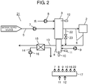
- a configuration of fuel cell system 21 according to a second exemplary embodiment of the present invention is hereinafter described with reference to FIG. 2 .
- FIG. 2 is a block diagram illustrating an example of the configuration of fuel cell system 21 according to the second exemplary embodiment.
- fuel cell system 21 is different from fuel cell system 1 illustrated in FIG. 1 in that bypass channel 22, and bypass isolation valve 23 in a course of bypass channel 22 are further provided.
- bypass channel 22 is configured to branch from fuel gas channel 6 on the upstream side of fuel cell 2, and join fuel gas channel 6 on the downstream side of fuel cell 2.
- Constituent elements in the present exemplary embodiment other than the foregoing constituent elements are similar to the corresponding constituent elements in the first exemplary embodiment. Accordingly, constituent elements identical or equivalent to the corresponding constituent elements illustrated in FIG. 1 have been given similar reference numbers, and the same explanation is not repeated.
- controller 17 After completion of a start step of fuel cell system 21, controller 17 initially starts an electricity generation step.
- booster pump 7 supplies material gas from a material supply source to hydrogen generator 3 via material gas channel 5 under control by controller 17.
- temperature sensor 12 detects a temperature of hydrogen generator 3 heated by combustion within burner 4.
- water pump 8 supplies water to hydrogen generator 3 under control by controller 17. This process prevents carbon deposition by a catalyst of hydrogen generator 3.
- hydrogen generator 3 reforms the supplied material gas and water by using the catalyst. Hydrogen generator 3 thereby generates fuel gas rich in hydrogen.
- controller 17 opens bypass isolation valve 23 provided in the course of bypass channel 22.
- This configuration produces a bypass route of bypass channel 22 which bypasses the anode of fuel cell 2.
- fuel gas to be burned by burner 4 is directly supplied from hydrogen generator 3 to burner 4, and the fuel gas is burned for a predetermined time (e.g., period required for decreasing carbon monoxide amount in fuel gas to predetermined amount or smaller).
- a predetermined time e.g., period required for decreasing carbon monoxide amount in fuel gas to predetermined amount or smaller.
- processing proceeds to an electricity generation step performed by fuel cell 2 under control by controller 17 after an elapse of a predetermined time.
- controller 17 closes bypass isolation valve 23 to isolate bypass channel 22.
- controller 17 supplies fuel gas discharged from hydrogen generator 3 to the anode of fuel cell 2 via fuel gas channel 6.
- controller 17 supplies air to the cathode of fuel cell 2 as oxidant gas.
- Fuel cell 2 thus generates electricity by utilizing electrochemical reaction between the supplied fuel gas and oxidant gas. During this reaction, heat is generated as well as electricity. Accordingly, a temperature of fuel cell 2 becomes higher than an outside temperature.
- Fuel cell 2 generates DC power, and outputs the DC power to the outside.
- the output DC power is converted into AC power by an inverter (not illustrated).
- the AC power thus converted is supplied to a load (e.g., electric device for home use) in cooperation with a power system.
- burner 4 burns fuel gas not consumed by fuel cell 2 for electricity generation and discharged from fuel cell 2. Combustion heat thus generated from the fuel gas is supplied to hydrogen generator 3 to heat hydrogen generator 3. As a result, reaction efficiency at hydrogen generator 3 is improved.
- Fuel cell system 21 operates in the manner described above.
- controller 17 shifts to a stop step to start a stop operation.
- controller 17 decreases supply of fuel gas and oxidant gas to fuel cell 2, and then stops only supply of oxidant gas.
- only fuel gas is supplied to fuel cell 2.
- oxygen remaining in the cathode reacts with fuel gas supplied to the anode.
- cell voltage of fuel cell 2 sharply drops.
- controller 17 stops supply of fuel gas to fuel cell 2 to end the stop step.
- Fuel cell system 21 of the present exemplary embodiment therefore performs a following hydrogen-containing gas supply process to prevent entrance of oxygen into the anode of fuel cell 2.
- booster pump 7 supplies material gas to hydrogen generator 3 under control by controller 17. Thereafter, controller 17 opens bypass isolation valve 23 to directly supply fuel gas discharged from hydrogen generator 3 to burner 4 through the route bypassing fuel cell 2. The fuel gas thus supplied to burner 4 is ignited by igniter 10 to burn the fuel gas within burner 4. As a result, hydrogen generator 3 is heated.
- bypass isolation valve 23 is opened to produce a route bypassing fuel cell 2, whereby deterioration of fuel cell 2 caused by a large amount of carbon monoxide contained in fuel gas discharged from hydrogen generator 3 in the initial period of the start is more reliably reduced.
- controller 17 When it is subsequently detected that the temperature of hydrogen generator 3 has increased to a predetermined temperature or higher in accordance with heating by burner 4, water pump 8 supplies water to hydrogen generator 3 under control by controller 17. This process prevents carbon deposition by a catalyst of hydrogen generator 3. After an elapse of a predetermined time, controller 17 closes bypass isolation valve 23. Subsequently, controller 17 supplies fuel gas discharged from hydrogen generator 3 to the anode of fuel cell 2 via fuel gas channel 6.
- air fan 9 supplies air to burner 4 under control by controller 17.
- igniter 10 ignites fuel gas within burner 4 under control by controller 17.
- Controller 17 thus detects a combustion state inside burner 4 based on detection by flame rod 11. Accordingly, whether or not fuel gas has been supplied to the anode of fuel cell 2 is accurately checked. More specifically, it is determined that fuel gas has been supplied to burner via the anode of fuel cell 2 based on detection of a combustion state inside the burner 4 by flame rod 11. Accordingly, it is determined that fuel gas is reliably supplied to the anode of fuel cell 2.
- controller 17 operates booster pump 7 such that material gas is supplied to at least hydrogen generator 3 at a predetermined time after an operation stop of hydrogen generator 3. Controller 17 further controls igniter 10 such that ignition takes place at burner 4. Thereafter, controller 17 detects combustion inside burner 4 based on detection by flame rod 11. It is therefore accurately determined whether or not the hydrogen-containing gas supply process for supplying hydrogen-containing gas to the anode has been performed. As a result, performance deterioration of fuel cell 2 is reduced by reduction of deterioration of resistance of the anode to carbon monoxide poisoning.
- the fuel cell system according to the present invention is defined in claim 1.
- the material gas is supplied to at least the hydrogen generator, and ignition is performed at the combustor. Accordingly, a combustion state of the combustor is detected by the combustion detector to accurately determine whether or not a hydrogen-containing gas supply process has been performed. As a result, performance deterioration of the fuel cell is effectively reduced by performing the hydrogen-containing gas supply process for supplying hydrogen-containing gas to the fuel cell.
- the fuel cell system further includes: a bypass channel that branches from an upstream side of the fuel gas channel through which the fuel gas discharged from the hydrogen generator is supplied to the fuel cell, and connects to a downstream side of the fuel gas channel through which the fuel gas discharged from the fuel cell is supplied to the combustor; and a bypass isolation valve provided in the bypass channel.
- the controller may control the material supplying unit such that the material gas is supplied to at least the hydrogen generator at a predetermined time after operation stops of the hydrogen generator and the fuel cell.
- the controller may subsequently open the bypass isolation valve, supply the fuel gas discharged from the hydrogen generator to the combustor along a bypass that bypasses the fuel cell, and control the ignition device such that ignition is performed at the combustor.
- the bypass isolation valve is opened to produce a route bypassing the fuel cell.
- the controller may control the material supplying unit such that supply of the material gas stops when the combustion detector detects combustion of the combustor after operation stops of the hydrogen generator and the fuel cell. According to configuration, wasteful consumption of material gas can be prevented.
- the fuel cell system according to the present invention further includes: an exhaust gas channel through which combustion exhaust gas is discharged from the combustor; a heat recovery channel through which heat is collected from the exhaust gas channel; a heat exchanger that performs heat exchange between the exhaust gas channel and the heat recovery channel; and a heat recovery pump that supplies a heat medium to the heat recovery channel.
- the controller may operate the heat recovery pump when the ignition device performs the ignition, or when the combustion detector detects combustion.
- the controller operates the heat recovery pump when the ignition is performed, or when the combustion detector detects combustion.
- a temperature of the combustion exhaust gas can be lowered.
- heat of combustion exhaust gas can be collected by the heat medium of the heat recovery channel.
- freezing of the heat medium flowing within the heat recovery channel can be prevented even at a low outside temperature, such as in a winter season.
- the fuel cell system according to claim 1 of the present invention further includes a temperature detector that detects a temperature of the hydrogen generator.
- the predetermined time may be any time as long as the temperature of the hydrogen generator at the time decreases to a temperature lower than a predetermined temperature.
- the temperature of the hydrogen generator having decreased to a temperature close to an ambient temperature does not further decrease but is kept substantially unchanged. Accordingly, reduction of a consumption amount of material gas can be achieved by reduction of unnecessary supply of the material gas to an anode of the fuel cell.
- the controller of the fuel cell system may control the material supplying unit such that supply of the material gas stops, and may issue notification to indicate abnormality, when the combustion detector does not detect combustion of the combustor even after repetition of the ignition by the ignition device a predetermined number of times.
- This configuration notifies about such an abnormal state that fuel gas cannot be supplied to the anode of the fuel cell. Accordingly, reduction of performance deterioration of the fuel cell can be achieved.
- a fuel cell system according to the present invention is capable of detecting presence or absence of combustion based on detection by a combustion detector to determine whether a hydrogen-containing gas supply process has been reliably performed. Accordingly, the fuel cell system of the present invention is a useful system applicable to a fuel cell system including a combustion detector which detects combustion of a combustor for heating a hydrogen generator, for example.
Landscapes
- Chemical & Material Sciences (AREA)
- Chemical Kinetics & Catalysis (AREA)
- Engineering & Computer Science (AREA)
- General Chemical & Material Sciences (AREA)
- Sustainable Energy (AREA)
- Sustainable Development (AREA)
- Manufacturing & Machinery (AREA)
- Electrochemistry (AREA)
- Life Sciences & Earth Sciences (AREA)
- Organic Chemistry (AREA)
- Health & Medical Sciences (AREA)
- General Health & Medical Sciences (AREA)
- Combustion & Propulsion (AREA)
- Inorganic Chemistry (AREA)
- Fuel Cell (AREA)
- Hydrogen, Water And Hydrids (AREA)
Claims (5)
- Brennstoffzellensystem, mit:einem Wasserstofferzeuger (3), der ausgebildet ist, Materialgas zu reformieren und Wasserstoff enthaltendes Gas zu erzeugen;einer Materialzuführeinheit (7), die ausgebildet ist, das Materialgas dem Wasserstofferzeuger (3) zuzuführen;einer Brennstoffzelle (2), die ausgebildet ist, elektrische Energie durch Verwenden von Wasserstoff enthaltendem Gas, das von dem Wasserstofferzeuger (3) abgegeben wird, und von oxidierendem Gas zu erzeugen;einer Verbrennungseinheit (4), die ausgebildet ist, den Wasserstofferzeuger (3) zu heizen; einem Brennstoffgaskanal (6), durch welchen von dem Wasserstofferzeuger (3) abgegebenes Brennstoffgas über die Brennstoffzelle (2) der Verbrennungseinheit (4) zugeführt wird;einer Zündeinrichtung (10), die ausgebildet ist, ein Zünden in der Verbrennungseinheit (4) auszuführen;einem Verbrennungsdetektor (11), der ausgebildet ist, eine Verbrennung der Verbrennungseinheit (4) zu erfassen;einem Temperaturdetektor (12), der ausgebildet ist, eine Temperatur des Wasserstofferzeugers (3) zu erfassen; undeiner Steuerung (17)dadurch gekennzeichnet, dasszu einer vorbestimmten Zeit nach einer Betriebsunterbrechung des Wasserstofferzeugers (3) und der Brennstoffzelle (2) die Steuerung (17) ausgebildet ist, die Materialzuführeinheit (7) derart zu steuern, dass das Materialgas zumindest dem Wasserstofferzeuger (3) zugeführt wird, und die Zündeinrichtung (10) derart zu steuern, dass eine Zündung in der Verbrennungseinheit (4) ausgeführt wird,wobei die vorbestimmte Zeit eine Zeit ist, wenn die Temperatur des Wasserstofferzeugers (3) auf eine Temperatur abnimmt, die niedriger als eine vorbestimmte Temperatur ist, und wobei die vorbestimmte Temperatur nahe bei der Umgebungstemperatur liegt.
- Brennstoffzellensystem nach Anspruch 1, das ferner aufweist:einen Umgehungskanal (22), der von einer Stromaufwärtsseite des Brennstoffgaskanals (6) abzweigt, durch die das von dem Wasserstofferzeuger (3) abgegebene Brennstoffgas der Brennstoffzelle (2) zugeführt wird, und der mit einer Stromabwärtsseite des Brennstoffgaskanals (6) verbunden ist, durch die das aus der Brennstoffzelle (2) abgegebene Brennstoffgas der Verbrennungseinheit (4) zugeführt wird; undein Umgehungstrennventil (23), das in dem Umgehungskanal (22) vorgesehen ist,wobei die Steuerung (17) ausgebildet ist,die Materialzuführeinheit (7) derart zu steuern, dass das Materialgas zu einer vorbestimmten Zeit nach einer Unterbrechung des Betriebs des Wasserstofferzeugers (3) und der Brennstoffzelle (2) zumindest dem Wasserstofferzeuger (3) zugeführt wird,das Umgehungstrennventil (23) zu öffnen,das aus dem Wasserstofferzeuger (3) abgegebene Brennstoffgas der Verbrennungseinheit (4) entlang einer Umgehung zuzuführen, die die Brennstoffzelle (2) umgeht, unddie Zündeinrichtung (10) derart zu steuern, dass eine Zündung in der Verbrennungseinheit (4) ausgeführt wird.
- Brennstoffzellensystem nach Anspruch 1, wobei die Steuerung (17) ausgebildet ist, die Materialzuführeinheit (7) derart zu steuern, dass die Zufuhr des Materialgases unterbrochen wird, wenn der Verbrennungsdetektor (11) eine Verbrennung in der Verbrennungseinheit (4) nach einer Unterbrechung des Betriebs des Wasserstofferzeugers (3) und der Brennstoffzelle (2) erfasst.
- Brennstoffzellensystem nach Anspruch 1, das ferner aufweist:einen Abgaskanal (13), durch den Verbrennungsabgas aus der Verbrennungseinheit (4) abgegeben wird;einen Wärmerückgewinnungskanal (14), durch welchen Wärme aus dem Abgaskanal (13) gesammelt wird;einen Wärmetauscher (15), der ausgebildet ist, den Wärmeaustausch zwischen dem Abgaskanal (13) und dem Wärmerückgewinnungskanal (14) auszuführen; undeine Wärmerückgewinnungspumpe (16), die ausgebildet ist, dem Wärmerückgewinnungskanal (14) ein Wärmemedium zuzuführen,wobei die Steuerung (17) ausgebildet ist, die Wärmerückgewinnungspumpe (16) zu aktivieren, wenn die Zündeinrichtung (10) die Zündung ausführt, oder wenn der Verbrennungsdetektor (11) eine Verbrennung erfasst.
- Brennstoffzellensystem nach Anspruch 1, wobei, wenn der Verbrennungsdetektor (11) eine Verbrennung in der Verbrennungseinheit (4) selbst nach einer vorbestimmten Anzahl an Wiederholungen des Zündens durch die Zündeinrichtung (10) nicht erfasst, die Steuerung (17) ausgebildet ist, die Materialzuführeinheit (7) derart zu steuern, dass die Zufuhr des Materialgases unterbrochen und eine Benachrichtigung ausgegeben wird, um diese Normabweichung anzuzeigen.
Applications Claiming Priority (2)
| Application Number | Priority Date | Filing Date | Title |
|---|---|---|---|
| JP2015067874 | 2015-03-30 | ||
| PCT/JP2016/001252 WO2016157738A1 (ja) | 2015-03-30 | 2016-03-08 | 燃料電池システム |
Publications (3)
| Publication Number | Publication Date |
|---|---|
| EP3279992A1 EP3279992A1 (de) | 2018-02-07 |
| EP3279992A4 EP3279992A4 (de) | 2018-02-14 |
| EP3279992B1 true EP3279992B1 (de) | 2019-09-11 |
Family
ID=57005428
Family Applications (1)
| Application Number | Title | Priority Date | Filing Date |
|---|---|---|---|
| EP16771632.3A Active EP3279992B1 (de) | 2015-03-30 | 2016-03-08 | Brennstoffzellensystem |
Country Status (3)
| Country | Link |
|---|---|
| EP (1) | EP3279992B1 (de) |
| JP (1) | JP6511650B2 (de) |
| WO (1) | WO2016157738A1 (de) |
Families Citing this family (1)
| Publication number | Priority date | Publication date | Assignee | Title |
|---|---|---|---|---|
| DE102021118406A1 (de) * | 2021-07-16 | 2023-01-19 | Viessmann Climate Solutions Se | Brennervorrichtung und Verfahren zum Betrieb einer Brennervorrichtung |
Family Cites Families (8)
| Publication number | Priority date | Publication date | Assignee | Title |
|---|---|---|---|---|
| JP2005332834A (ja) * | 2002-02-07 | 2005-12-02 | Matsushita Electric Ind Co Ltd | 燃料電池発電システムおよび燃料電池発電システムの制御方法 |
| EP1557395B1 (de) * | 2004-01-22 | 2012-07-04 | Panasonic Corporation | Wasserstoffgenerator und Brennstoffzellensystem |
| JP2006001780A (ja) * | 2004-06-17 | 2006-01-05 | Babcock Hitachi Kk | 水素製造装置およびその起動方法 |
| JP2007335332A (ja) * | 2006-06-16 | 2007-12-27 | Ebara Ballard Corp | 燃料電池システム |
| JP2010015937A (ja) * | 2008-07-07 | 2010-01-21 | Toshiba Fuel Cell Power Systems Corp | 燃料電池発電装置 |
| CN102369624B (zh) * | 2009-03-31 | 2016-06-15 | 松下电器产业株式会社 | 燃料电池系统 |
| JP5605106B2 (ja) * | 2010-09-13 | 2014-10-15 | パナソニック株式会社 | 燃料電池発電装置 |
| JP2014172815A (ja) * | 2013-03-13 | 2014-09-22 | Panasonic Corp | 水素生成装置 |
-
2016
- 2016-03-08 JP JP2017509226A patent/JP6511650B2/ja active Active
- 2016-03-08 EP EP16771632.3A patent/EP3279992B1/de active Active
- 2016-03-08 WO PCT/JP2016/001252 patent/WO2016157738A1/ja not_active Ceased
Non-Patent Citations (1)
| Title |
|---|
| None * |
Also Published As
| Publication number | Publication date |
|---|---|
| EP3279992A1 (de) | 2018-02-07 |
| JP6511650B2 (ja) | 2019-05-15 |
| EP3279992A4 (de) | 2018-02-14 |
| WO2016157738A1 (ja) | 2016-10-06 |
| JPWO2016157738A1 (ja) | 2018-02-22 |
Similar Documents
| Publication | Publication Date | Title |
|---|---|---|
| EP2053680A1 (de) | Brennstoffzellensystem | |
| EP2383824A1 (de) | Brennstoffzellensystem und verfahren zum betreiben dieses systems | |
| US9685672B2 (en) | Hydrogen generation apparatus, fuel cell system including the same, method of operating hydrogen generation apparatus and method of operating fuel cell system | |
| JP2003197231A (ja) | 燃料電池発電システムおよびその制御方法 | |
| EP2416428A1 (de) | Brennstoffzellensystem | |
| JP5148681B2 (ja) | 燃料電池システム | |
| EP2677585B1 (de) | Stromerzeugungssystem und betriebsverfahren dafür | |
| CN103119769B (zh) | 固体氧化物型燃料电池装置 | |
| EP3279992B1 (de) | Brennstoffzellensystem | |
| JP2010238520A (ja) | 燃料電池システム | |
| US7811712B2 (en) | Fuel cell system and operation method thereof | |
| JP5735606B2 (ja) | 燃料電池システムの停止保管方法 | |
| JP2006153595A (ja) | ガス検出装置及びガス検出方法 | |
| JP5986236B2 (ja) | 固体酸化物形燃料電池システム | |
| JP5864059B2 (ja) | 燃料電池システムおよびこれの故障診断方法 | |
| JP2014089890A (ja) | 燃料電池式発電装置及びコージェネレーションシステム | |
| JP2014111509A (ja) | 水素生成装置及びその運転方法 | |
| JP2006179224A (ja) | 燃料電池システム | |
| JP5607951B2 (ja) | 燃料電池システムの停止状態維持方法 | |
| JP2012119244A (ja) | 燃料電池システム | |
| JP2014116069A (ja) | 燃料電池システム | |
| JP2008108667A (ja) | 燃料電池システム | |
| JP2006294498A (ja) | 燃料電池システム | |
| US20140023944A1 (en) | Fuel cell system and method of operating same | |
| JP2012089236A (ja) | 燃料電池システム |
Legal Events
| Date | Code | Title | Description |
|---|---|---|---|
| STAA | Information on the status of an ep patent application or granted ep patent |
Free format text: STATUS: THE INTERNATIONAL PUBLICATION HAS BEEN MADE |
|
| PUAI | Public reference made under article 153(3) epc to a published international application that has entered the european phase |
Free format text: ORIGINAL CODE: 0009012 |
|
| STAA | Information on the status of an ep patent application or granted ep patent |
Free format text: STATUS: REQUEST FOR EXAMINATION WAS MADE |
|
| 17P | Request for examination filed |
Effective date: 20171016 |
|
| AK | Designated contracting states |
Kind code of ref document: A1 Designated state(s): AL AT BE BG CH CY CZ DE DK EE ES FI FR GB GR HR HU IE IS IT LI LT LU LV MC MK MT NL NO PL PT RO RS SE SI SK SM TR |
|
| AX | Request for extension of the european patent |
Extension state: BA ME |
|
| A4 | Supplementary search report drawn up and despatched |
Effective date: 20180111 |
|
| DAV | Request for validation of the european patent (deleted) | ||
| DAX | Request for extension of the european patent (deleted) | ||
| GRAP | Despatch of communication of intention to grant a patent |
Free format text: ORIGINAL CODE: EPIDOSNIGR1 |
|
| STAA | Information on the status of an ep patent application or granted ep patent |
Free format text: STATUS: GRANT OF PATENT IS INTENDED |
|
| INTG | Intention to grant announced |
Effective date: 20190418 |
|
| GRAS | Grant fee paid |
Free format text: ORIGINAL CODE: EPIDOSNIGR3 |
|
| GRAA | (expected) grant |
Free format text: ORIGINAL CODE: 0009210 |
|
| STAA | Information on the status of an ep patent application or granted ep patent |
Free format text: STATUS: THE PATENT HAS BEEN GRANTED |
|
| AK | Designated contracting states |
Kind code of ref document: B1 Designated state(s): AL AT BE BG CH CY CZ DE DK EE ES FI FR GB GR HR HU IE IS IT LI LT LU LV MC MK MT NL NO PL PT RO RS SE SI SK SM TR |
|
| REG | Reference to a national code |
Ref country code: GB Ref legal event code: FG4D |
|
| REG | Reference to a national code |
Ref country code: CH Ref legal event code: EP |
|
| REG | Reference to a national code |
Ref country code: AT Ref legal event code: REF Ref document number: 1179668 Country of ref document: AT Kind code of ref document: T Effective date: 20190915 |
|
| REG | Reference to a national code |
Ref country code: DE Ref legal event code: R096 Ref document number: 602016020496 Country of ref document: DE |
|
| REG | Reference to a national code |
Ref country code: IE Ref legal event code: FG4D |
|
| REG | Reference to a national code |
Ref country code: NL Ref legal event code: MP Effective date: 20190911 |
|
| REG | Reference to a national code |
Ref country code: LT Ref legal event code: MG4D |
|
| PG25 | Lapsed in a contracting state [announced via postgrant information from national office to epo] |
Ref country code: HR Free format text: LAPSE BECAUSE OF FAILURE TO SUBMIT A TRANSLATION OF THE DESCRIPTION OR TO PAY THE FEE WITHIN THE PRESCRIBED TIME-LIMIT Effective date: 20190911 Ref country code: BG Free format text: LAPSE BECAUSE OF FAILURE TO SUBMIT A TRANSLATION OF THE DESCRIPTION OR TO PAY THE FEE WITHIN THE PRESCRIBED TIME-LIMIT Effective date: 20191211 Ref country code: LT Free format text: LAPSE BECAUSE OF FAILURE TO SUBMIT A TRANSLATION OF THE DESCRIPTION OR TO PAY THE FEE WITHIN THE PRESCRIBED TIME-LIMIT Effective date: 20190911 Ref country code: NO Free format text: LAPSE BECAUSE OF FAILURE TO SUBMIT A TRANSLATION OF THE DESCRIPTION OR TO PAY THE FEE WITHIN THE PRESCRIBED TIME-LIMIT Effective date: 20191211 Ref country code: SE Free format text: LAPSE BECAUSE OF FAILURE TO SUBMIT A TRANSLATION OF THE DESCRIPTION OR TO PAY THE FEE WITHIN THE PRESCRIBED TIME-LIMIT Effective date: 20190911 Ref country code: FI Free format text: LAPSE BECAUSE OF FAILURE TO SUBMIT A TRANSLATION OF THE DESCRIPTION OR TO PAY THE FEE WITHIN THE PRESCRIBED TIME-LIMIT Effective date: 20190911 |
|
| PG25 | Lapsed in a contracting state [announced via postgrant information from national office to epo] |
Ref country code: RS Free format text: LAPSE BECAUSE OF FAILURE TO SUBMIT A TRANSLATION OF THE DESCRIPTION OR TO PAY THE FEE WITHIN THE PRESCRIBED TIME-LIMIT Effective date: 20190911 Ref country code: AL Free format text: LAPSE BECAUSE OF FAILURE TO SUBMIT A TRANSLATION OF THE DESCRIPTION OR TO PAY THE FEE WITHIN THE PRESCRIBED TIME-LIMIT Effective date: 20190911 Ref country code: ES Free format text: LAPSE BECAUSE OF FAILURE TO SUBMIT A TRANSLATION OF THE DESCRIPTION OR TO PAY THE FEE WITHIN THE PRESCRIBED TIME-LIMIT Effective date: 20190911 Ref country code: GR Free format text: LAPSE BECAUSE OF FAILURE TO SUBMIT A TRANSLATION OF THE DESCRIPTION OR TO PAY THE FEE WITHIN THE PRESCRIBED TIME-LIMIT Effective date: 20191212 Ref country code: LV Free format text: LAPSE BECAUSE OF FAILURE TO SUBMIT A TRANSLATION OF THE DESCRIPTION OR TO PAY THE FEE WITHIN THE PRESCRIBED TIME-LIMIT Effective date: 20190911 |
|
| REG | Reference to a national code |
Ref country code: AT Ref legal event code: MK05 Ref document number: 1179668 Country of ref document: AT Kind code of ref document: T Effective date: 20190911 |
|
| PG25 | Lapsed in a contracting state [announced via postgrant information from national office to epo] |
Ref country code: NL Free format text: LAPSE BECAUSE OF FAILURE TO SUBMIT A TRANSLATION OF THE DESCRIPTION OR TO PAY THE FEE WITHIN THE PRESCRIBED TIME-LIMIT Effective date: 20190911 Ref country code: IT Free format text: LAPSE BECAUSE OF FAILURE TO SUBMIT A TRANSLATION OF THE DESCRIPTION OR TO PAY THE FEE WITHIN THE PRESCRIBED TIME-LIMIT Effective date: 20190911 Ref country code: EE Free format text: LAPSE BECAUSE OF FAILURE TO SUBMIT A TRANSLATION OF THE DESCRIPTION OR TO PAY THE FEE WITHIN THE PRESCRIBED TIME-LIMIT Effective date: 20190911 Ref country code: AT Free format text: LAPSE BECAUSE OF FAILURE TO SUBMIT A TRANSLATION OF THE DESCRIPTION OR TO PAY THE FEE WITHIN THE PRESCRIBED TIME-LIMIT Effective date: 20190911 Ref country code: RO Free format text: LAPSE BECAUSE OF FAILURE TO SUBMIT A TRANSLATION OF THE DESCRIPTION OR TO PAY THE FEE WITHIN THE PRESCRIBED TIME-LIMIT Effective date: 20190911 Ref country code: PT Free format text: LAPSE BECAUSE OF FAILURE TO SUBMIT A TRANSLATION OF THE DESCRIPTION OR TO PAY THE FEE WITHIN THE PRESCRIBED TIME-LIMIT Effective date: 20200113 Ref country code: PL Free format text: LAPSE BECAUSE OF FAILURE TO SUBMIT A TRANSLATION OF THE DESCRIPTION OR TO PAY THE FEE WITHIN THE PRESCRIBED TIME-LIMIT Effective date: 20190911 |
|
| PG25 | Lapsed in a contracting state [announced via postgrant information from national office to epo] |
Ref country code: SM Free format text: LAPSE BECAUSE OF FAILURE TO SUBMIT A TRANSLATION OF THE DESCRIPTION OR TO PAY THE FEE WITHIN THE PRESCRIBED TIME-LIMIT Effective date: 20190911 Ref country code: IS Free format text: LAPSE BECAUSE OF FAILURE TO SUBMIT A TRANSLATION OF THE DESCRIPTION OR TO PAY THE FEE WITHIN THE PRESCRIBED TIME-LIMIT Effective date: 20200224 Ref country code: SK Free format text: LAPSE BECAUSE OF FAILURE TO SUBMIT A TRANSLATION OF THE DESCRIPTION OR TO PAY THE FEE WITHIN THE PRESCRIBED TIME-LIMIT Effective date: 20190911 Ref country code: CZ Free format text: LAPSE BECAUSE OF FAILURE TO SUBMIT A TRANSLATION OF THE DESCRIPTION OR TO PAY THE FEE WITHIN THE PRESCRIBED TIME-LIMIT Effective date: 20190911 |
|
| REG | Reference to a national code |
Ref country code: DE Ref legal event code: R097 Ref document number: 602016020496 Country of ref document: DE |
|
| PLBE | No opposition filed within time limit |
Free format text: ORIGINAL CODE: 0009261 |
|
| STAA | Information on the status of an ep patent application or granted ep patent |
Free format text: STATUS: NO OPPOSITION FILED WITHIN TIME LIMIT |
|
| PG2D | Information on lapse in contracting state deleted |
Ref country code: IS |
|
| PG25 | Lapsed in a contracting state [announced via postgrant information from national office to epo] |
Ref country code: DK Free format text: LAPSE BECAUSE OF FAILURE TO SUBMIT A TRANSLATION OF THE DESCRIPTION OR TO PAY THE FEE WITHIN THE PRESCRIBED TIME-LIMIT Effective date: 20190911 Ref country code: IS Free format text: LAPSE BECAUSE OF FAILURE TO SUBMIT A TRANSLATION OF THE DESCRIPTION OR TO PAY THE FEE WITHIN THE PRESCRIBED TIME-LIMIT Effective date: 20200112 |
|
| 26N | No opposition filed |
Effective date: 20200615 |
|
| PG25 | Lapsed in a contracting state [announced via postgrant information from national office to epo] |
Ref country code: SI Free format text: LAPSE BECAUSE OF FAILURE TO SUBMIT A TRANSLATION OF THE DESCRIPTION OR TO PAY THE FEE WITHIN THE PRESCRIBED TIME-LIMIT Effective date: 20190911 |
|
| PG25 | Lapsed in a contracting state [announced via postgrant information from national office to epo] |
Ref country code: MC Free format text: LAPSE BECAUSE OF FAILURE TO SUBMIT A TRANSLATION OF THE DESCRIPTION OR TO PAY THE FEE WITHIN THE PRESCRIBED TIME-LIMIT Effective date: 20190911 |
|
| REG | Reference to a national code |
Ref country code: CH Ref legal event code: PL |
|
| REG | Reference to a national code |
Ref country code: BE Ref legal event code: MM Effective date: 20200331 |
|
| PG25 | Lapsed in a contracting state [announced via postgrant information from national office to epo] |
Ref country code: LU Free format text: LAPSE BECAUSE OF NON-PAYMENT OF DUE FEES Effective date: 20200308 |
|
| PG25 | Lapsed in a contracting state [announced via postgrant information from national office to epo] |
Ref country code: CH Free format text: LAPSE BECAUSE OF NON-PAYMENT OF DUE FEES Effective date: 20200331 Ref country code: LI Free format text: LAPSE BECAUSE OF NON-PAYMENT OF DUE FEES Effective date: 20200331 Ref country code: FR Free format text: LAPSE BECAUSE OF NON-PAYMENT OF DUE FEES Effective date: 20200331 Ref country code: IE Free format text: LAPSE BECAUSE OF NON-PAYMENT OF DUE FEES Effective date: 20200308 |
|
| PG25 | Lapsed in a contracting state [announced via postgrant information from national office to epo] |
Ref country code: BE Free format text: LAPSE BECAUSE OF NON-PAYMENT OF DUE FEES Effective date: 20200331 |
|
| PG25 | Lapsed in a contracting state [announced via postgrant information from national office to epo] |
Ref country code: TR Free format text: LAPSE BECAUSE OF FAILURE TO SUBMIT A TRANSLATION OF THE DESCRIPTION OR TO PAY THE FEE WITHIN THE PRESCRIBED TIME-LIMIT Effective date: 20190911 Ref country code: MT Free format text: LAPSE BECAUSE OF FAILURE TO SUBMIT A TRANSLATION OF THE DESCRIPTION OR TO PAY THE FEE WITHIN THE PRESCRIBED TIME-LIMIT Effective date: 20190911 Ref country code: CY Free format text: LAPSE BECAUSE OF FAILURE TO SUBMIT A TRANSLATION OF THE DESCRIPTION OR TO PAY THE FEE WITHIN THE PRESCRIBED TIME-LIMIT Effective date: 20190911 |
|
| PG25 | Lapsed in a contracting state [announced via postgrant information from national office to epo] |
Ref country code: MK Free format text: LAPSE BECAUSE OF FAILURE TO SUBMIT A TRANSLATION OF THE DESCRIPTION OR TO PAY THE FEE WITHIN THE PRESCRIBED TIME-LIMIT Effective date: 20190911 |
|
| PGFP | Annual fee paid to national office [announced via postgrant information from national office to epo] |
Ref country code: DE Payment date: 20250319 Year of fee payment: 10 |
|
| REG | Reference to a national code |
Ref country code: DE Ref legal event code: R084 Ref document number: 602016020496 Country of ref document: DE |
|
| PGFP | Annual fee paid to national office [announced via postgrant information from national office to epo] |
Ref country code: GB Payment date: 20260324 Year of fee payment: 11 |