EP3277403B1 - Multifunctional filters for diesel emission control - Google Patents
Multifunctional filters for diesel emission control Download PDFInfo
- Publication number
- EP3277403B1 EP3277403B1 EP16774106.5A EP16774106A EP3277403B1 EP 3277403 B1 EP3277403 B1 EP 3277403B1 EP 16774106 A EP16774106 A EP 16774106A EP 3277403 B1 EP3277403 B1 EP 3277403B1
- Authority
- EP
- European Patent Office
- Prior art keywords
- catalyst
- coating
- length
- wall
- porous
- Prior art date
- Legal status (The legal status is an assumption and is not a legal conclusion. Google has not performed a legal analysis and makes no representation as to the accuracy of the status listed.)
- Active
Links
- 239000003054 catalyst Substances 0.000 claims description 387
- 238000000576 coating method Methods 0.000 claims description 174
- 239000011248 coating agent Substances 0.000 claims description 145
- 238000011068 loading method Methods 0.000 claims description 127
- 238000007254 oxidation reaction Methods 0.000 claims description 118
- 230000003647 oxidation Effects 0.000 claims description 117
- 238000010531 catalytic reduction reaction Methods 0.000 claims description 112
- BASFCYQUMIYNBI-UHFFFAOYSA-N platinum Chemical group [Pt] BASFCYQUMIYNBI-UHFFFAOYSA-N 0.000 claims description 101
- 230000003197 catalytic effect Effects 0.000 claims description 87
- 229910052751 metal Inorganic materials 0.000 claims description 73
- 239000002184 metal Substances 0.000 claims description 73
- 239000002245 particle Substances 0.000 claims description 51
- 239000012466 permeate Substances 0.000 claims description 46
- 239000000203 mixture Substances 0.000 claims description 43
- VYPSYNLAJGMNEJ-UHFFFAOYSA-N Silicium dioxide Chemical compound O=[Si]=O VYPSYNLAJGMNEJ-UHFFFAOYSA-N 0.000 claims description 40
- 239000000463 material Substances 0.000 claims description 40
- XEEYBQQBJWHFJM-UHFFFAOYSA-N iron Substances [Fe] XEEYBQQBJWHFJM-UHFFFAOYSA-N 0.000 claims description 33
- 239000010949 copper Substances 0.000 claims description 24
- PNEYBMLMFCGWSK-UHFFFAOYSA-N aluminium oxide Inorganic materials [O-2].[O-2].[O-2].[Al+3].[Al+3] PNEYBMLMFCGWSK-UHFFFAOYSA-N 0.000 claims description 23
- 229910052802 copper Inorganic materials 0.000 claims description 23
- 239000002808 molecular sieve Substances 0.000 claims description 22
- URGAHOPLAPQHLN-UHFFFAOYSA-N sodium aluminosilicate Chemical compound [Na+].[Al+3].[O-][Si]([O-])=O.[O-][Si]([O-])=O URGAHOPLAPQHLN-UHFFFAOYSA-N 0.000 claims description 22
- 229910052742 iron Inorganic materials 0.000 claims description 20
- 239000000377 silicon dioxide Substances 0.000 claims description 20
- 238000000034 method Methods 0.000 claims description 19
- 230000001590 oxidative effect Effects 0.000 claims description 16
- 230000009467 reduction Effects 0.000 claims description 15
- 238000006722 reduction reaction Methods 0.000 claims description 15
- RYGMFSIKBFXOCR-UHFFFAOYSA-N Copper Chemical compound [Cu] RYGMFSIKBFXOCR-UHFFFAOYSA-N 0.000 claims description 14
- GWEVSGVZZGPLCZ-UHFFFAOYSA-N Titan oxide Chemical compound O=[Ti]=O GWEVSGVZZGPLCZ-UHFFFAOYSA-N 0.000 claims description 14
- MCMNRKCIXSYSNV-UHFFFAOYSA-N Zirconium dioxide Chemical compound O=[Zr]=O MCMNRKCIXSYSNV-UHFFFAOYSA-N 0.000 claims description 14
- 239000011148 porous material Substances 0.000 claims description 12
- 229910052720 vanadium Inorganic materials 0.000 claims description 8
- 229910052746 lanthanum Inorganic materials 0.000 claims description 7
- 229910052748 manganese Inorganic materials 0.000 claims description 7
- 229910052759 nickel Inorganic materials 0.000 claims description 7
- 239000010953 base metal Substances 0.000 claims description 6
- 238000004519 manufacturing process Methods 0.000 claims description 6
- 229910052709 silver Inorganic materials 0.000 claims description 5
- 229910052684 Cerium Inorganic materials 0.000 claims description 4
- 229910052750 molybdenum Inorganic materials 0.000 claims description 3
- 229910052721 tungsten Inorganic materials 0.000 claims description 3
- 239000000758 substrate Substances 0.000 description 66
- 238000006243 chemical reaction Methods 0.000 description 57
- QGZKDVFQNNGYKY-UHFFFAOYSA-N Ammonia Chemical compound N QGZKDVFQNNGYKY-UHFFFAOYSA-N 0.000 description 52
- 239000002002 slurry Substances 0.000 description 35
- 239000007789 gas Substances 0.000 description 24
- 239000013618 particulate matter Substances 0.000 description 21
- 239000004071 soot Substances 0.000 description 20
- MWUXSHHQAYIFBG-UHFFFAOYSA-N nitrogen oxide Inorganic materials O=[N] MWUXSHHQAYIFBG-UHFFFAOYSA-N 0.000 description 18
- 230000015572 biosynthetic process Effects 0.000 description 17
- 238000005755 formation reaction Methods 0.000 description 17
- KDLHZDBZIXYQEI-UHFFFAOYSA-N palladium Substances [Pd] KDLHZDBZIXYQEI-UHFFFAOYSA-N 0.000 description 17
- 229910021529 ammonia Inorganic materials 0.000 description 14
- 238000011144 upstream manufacturing Methods 0.000 description 13
- 239000007787 solid Substances 0.000 description 10
- 101100365087 Arabidopsis thaliana SCRA gene Proteins 0.000 description 9
- 101150105073 SCR1 gene Proteins 0.000 description 9
- 101100134054 Saccharomyces cerevisiae (strain ATCC 204508 / S288c) NTG1 gene Proteins 0.000 description 9
- XSQUKJJJFZCRTK-UHFFFAOYSA-N Urea Chemical compound NC(N)=O XSQUKJJJFZCRTK-UHFFFAOYSA-N 0.000 description 9
- 239000004202 carbamide Substances 0.000 description 9
- 238000013461 design Methods 0.000 description 9
- 101000668165 Homo sapiens RNA-binding motif, single-stranded-interacting protein 1 Proteins 0.000 description 8
- 102100039692 RNA-binding motif, single-stranded-interacting protein 1 Human genes 0.000 description 8
- 229910052697 platinum Inorganic materials 0.000 description 8
- 239000000843 powder Substances 0.000 description 8
- 238000010422 painting Methods 0.000 description 7
- XLYOFNOQVPJJNP-UHFFFAOYSA-N water Substances O XLYOFNOQVPJJNP-UHFFFAOYSA-N 0.000 description 7
- 230000004323 axial length Effects 0.000 description 6
- 230000008859 change Effects 0.000 description 6
- 238000002360 preparation method Methods 0.000 description 6
- IJGRMHOSHXDMSA-UHFFFAOYSA-N Atomic nitrogen Chemical compound N#N IJGRMHOSHXDMSA-UHFFFAOYSA-N 0.000 description 5
- CURLTUGMZLYLDI-UHFFFAOYSA-N Carbon dioxide Chemical compound O=C=O CURLTUGMZLYLDI-UHFFFAOYSA-N 0.000 description 5
- 229910002091 carbon monoxide Inorganic materials 0.000 description 5
- 238000011156 evaluation Methods 0.000 description 5
- 229930195733 hydrocarbon Natural products 0.000 description 5
- 150000002430 hydrocarbons Chemical class 0.000 description 5
- 239000007788 liquid Substances 0.000 description 5
- 229910052763 palladium Inorganic materials 0.000 description 5
- 238000012360 testing method Methods 0.000 description 5
- UGFAIRIUMAVXCW-UHFFFAOYSA-N Carbon monoxide Chemical compound [O+]#[C-] UGFAIRIUMAVXCW-UHFFFAOYSA-N 0.000 description 4
- QAOWNCQODCNURD-UHFFFAOYSA-N Sulfuric acid Chemical compound OS(O)(=O)=O QAOWNCQODCNURD-UHFFFAOYSA-N 0.000 description 4
- 229910002092 carbon dioxide Inorganic materials 0.000 description 4
- 239000003638 chemical reducing agent Substances 0.000 description 4
- 229910052593 corundum Inorganic materials 0.000 description 4
- 239000002283 diesel fuel Substances 0.000 description 4
- 230000008929 regeneration Effects 0.000 description 4
- 238000011069 regeneration method Methods 0.000 description 4
- 239000010948 rhodium Substances 0.000 description 4
- 229910001845 yogo sapphire Inorganic materials 0.000 description 4
- QTBSBXVTEAMEQO-UHFFFAOYSA-M Acetate Chemical compound CC([O-])=O QTBSBXVTEAMEQO-UHFFFAOYSA-M 0.000 description 3
- 229910021536 Zeolite Inorganic materials 0.000 description 3
- 238000013459 approach Methods 0.000 description 3
- 229910052799 carbon Inorganic materials 0.000 description 3
- 229910052681 coesite Inorganic materials 0.000 description 3
- 238000002485 combustion reaction Methods 0.000 description 3
- 229910052906 cristobalite Inorganic materials 0.000 description 3
- HNPSIPDUKPIQMN-UHFFFAOYSA-N dioxosilane;oxo(oxoalumanyloxy)alumane Chemical compound O=[Si]=O.O=[Al]O[Al]=O HNPSIPDUKPIQMN-UHFFFAOYSA-N 0.000 description 3
- 238000005516 engineering process Methods 0.000 description 3
- 239000003344 environmental pollutant Substances 0.000 description 3
- 230000037361 pathway Effects 0.000 description 3
- 230000035515 penetration Effects 0.000 description 3
- 231100000719 pollutant Toxicity 0.000 description 3
- 229910052703 rhodium Inorganic materials 0.000 description 3
- 239000000243 solution Substances 0.000 description 3
- 229910052682 stishovite Inorganic materials 0.000 description 3
- 229910052905 tridymite Inorganic materials 0.000 description 3
- 239000010457 zeolite Substances 0.000 description 3
- OKTJSMMVPCPJKN-UHFFFAOYSA-N Carbon Chemical compound [C] OKTJSMMVPCPJKN-UHFFFAOYSA-N 0.000 description 2
- KJTLSVCANCCWHF-UHFFFAOYSA-N Ruthenium Chemical compound [Ru] KJTLSVCANCCWHF-UHFFFAOYSA-N 0.000 description 2
- QAOWNCQODCNURD-UHFFFAOYSA-L Sulfate Chemical compound [O-]S([O-])(=O)=O QAOWNCQODCNURD-UHFFFAOYSA-L 0.000 description 2
- NINIDFKCEFEMDL-UHFFFAOYSA-N Sulfur Chemical compound [S] NINIDFKCEFEMDL-UHFFFAOYSA-N 0.000 description 2
- 239000000443 aerosol Substances 0.000 description 2
- 238000004458 analytical method Methods 0.000 description 2
- 238000001354 calcination Methods 0.000 description 2
- 239000000919 ceramic Substances 0.000 description 2
- 239000006185 dispersion Substances 0.000 description 2
- 238000001035 drying Methods 0.000 description 2
- 238000001914 filtration Methods 0.000 description 2
- 239000006260 foam Substances 0.000 description 2
- 229910052741 iridium Inorganic materials 0.000 description 2
- GKOZUEZYRPOHIO-UHFFFAOYSA-N iridium atom Chemical compound [Ir] GKOZUEZYRPOHIO-UHFFFAOYSA-N 0.000 description 2
- 239000010687 lubricating oil Substances 0.000 description 2
- 230000007246 mechanism Effects 0.000 description 2
- 238000002156 mixing Methods 0.000 description 2
- 229910052757 nitrogen Inorganic materials 0.000 description 2
- 229910052762 osmium Inorganic materials 0.000 description 2
- SYQBFIAQOQZEGI-UHFFFAOYSA-N osmium atom Chemical compound [Os] SYQBFIAQOQZEGI-UHFFFAOYSA-N 0.000 description 2
- 239000007800 oxidant agent Substances 0.000 description 2
- -1 platinum group metals Chemical class 0.000 description 2
- 239000002243 precursor Substances 0.000 description 2
- 230000008569 process Effects 0.000 description 2
- MHOVAHRLVXNVSD-UHFFFAOYSA-N rhodium atom Chemical compound [Rh] MHOVAHRLVXNVSD-UHFFFAOYSA-N 0.000 description 2
- 229910052707 ruthenium Inorganic materials 0.000 description 2
- 229910052717 sulfur Inorganic materials 0.000 description 2
- 239000011593 sulfur Substances 0.000 description 2
- 229910052723 transition metal Inorganic materials 0.000 description 2
- 150000003624 transition metals Chemical class 0.000 description 2
- 229910052726 zirconium Inorganic materials 0.000 description 2
- 238000013316 zoning Methods 0.000 description 2
- 239000004215 Carbon black (E152) Substances 0.000 description 1
- 229910002651 NO3 Inorganic materials 0.000 description 1
- NHNBFGGVMKEFGY-UHFFFAOYSA-N Nitrate Chemical compound [O-][N+]([O-])=O NHNBFGGVMKEFGY-UHFFFAOYSA-N 0.000 description 1
- RTAQQCXQSZGOHL-UHFFFAOYSA-N Titanium Chemical compound [Ti] RTAQQCXQSZGOHL-UHFFFAOYSA-N 0.000 description 1
- 239000007864 aqueous solution Substances 0.000 description 1
- QVGXLLKOCUKJST-UHFFFAOYSA-N atomic oxygen Chemical compound [O] QVGXLLKOCUKJST-UHFFFAOYSA-N 0.000 description 1
- 239000011230 binding agent Substances 0.000 description 1
- 238000007664 blowing Methods 0.000 description 1
- UNYSKUBLZGJSLV-UHFFFAOYSA-L calcium;1,3,5,2,4,6$l^{2}-trioxadisilaluminane 2,4-dioxide;dihydroxide;hexahydrate Chemical compound O.O.O.O.O.O.[OH-].[OH-].[Ca+2].O=[Si]1O[Al]O[Si](=O)O1.O=[Si]1O[Al]O[Si](=O)O1 UNYSKUBLZGJSLV-UHFFFAOYSA-L 0.000 description 1
- 239000001569 carbon dioxide Substances 0.000 description 1
- 239000011237 carbonaceous particulate material Substances 0.000 description 1
- 229910052676 chabazite Inorganic materials 0.000 description 1
- 238000004891 communication Methods 0.000 description 1
- 230000001010 compromised effect Effects 0.000 description 1
- 238000010276 construction Methods 0.000 description 1
- 230000002939 deleterious effect Effects 0.000 description 1
- 230000004069 differentiation Effects 0.000 description 1
- 239000000835 fiber Substances 0.000 description 1
- 239000012530 fluid Substances 0.000 description 1
- 239000000446 fuel Substances 0.000 description 1
- 239000008241 heterogeneous mixture Substances 0.000 description 1
- 230000010354 integration Effects 0.000 description 1
- 230000003993 interaction Effects 0.000 description 1
- 239000011159 matrix material Substances 0.000 description 1
- 238000005259 measurement Methods 0.000 description 1
- 229910044991 metal oxide Inorganic materials 0.000 description 1
- 150000004706 metal oxides Chemical class 0.000 description 1
- 150000002739 metals Chemical class 0.000 description 1
- VUZPPFZMUPKLLV-UHFFFAOYSA-N methane;hydrate Chemical compound C.O VUZPPFZMUPKLLV-UHFFFAOYSA-N 0.000 description 1
- 239000011268 mixed slurry Substances 0.000 description 1
- 239000001301 oxygen Substances 0.000 description 1
- 229910052760 oxygen Inorganic materials 0.000 description 1
- 230000002265 prevention Effects 0.000 description 1
- 238000012545 processing Methods 0.000 description 1
- 230000002035 prolonged effect Effects 0.000 description 1
- 230000001737 promoting effect Effects 0.000 description 1
- 239000003870 refractory metal Substances 0.000 description 1
- 230000001105 regulatory effect Effects 0.000 description 1
- 239000010944 silver (metal) Substances 0.000 description 1
- 239000007921 spray Substances 0.000 description 1
- 238000003756 stirring Methods 0.000 description 1
- 230000000153 supplemental effect Effects 0.000 description 1
- 239000000725 suspension Substances 0.000 description 1
- 238000010998 test method Methods 0.000 description 1
- 238000007669 thermal treatment Methods 0.000 description 1
- 229910052719 titanium Inorganic materials 0.000 description 1
- 239000010936 titanium Substances 0.000 description 1
- 230000001052 transient effect Effects 0.000 description 1
- LEONUFNNVUYDNQ-UHFFFAOYSA-N vanadium atom Chemical compound [V] LEONUFNNVUYDNQ-UHFFFAOYSA-N 0.000 description 1
- 239000011800 void material Substances 0.000 description 1
Images


Classifications
-
- B—PERFORMING OPERATIONS; TRANSPORTING
- B01—PHYSICAL OR CHEMICAL PROCESSES OR APPARATUS IN GENERAL
- B01D—SEPARATION
- B01D53/00—Separation of gases or vapours; Recovering vapours of volatile solvents from gases; Chemical or biological purification of waste gases, e.g. engine exhaust gases, smoke, fumes, flue gases, aerosols
- B01D53/34—Chemical or biological purification of waste gases
- B01D53/92—Chemical or biological purification of waste gases of engine exhaust gases
- B01D53/94—Chemical or biological purification of waste gases of engine exhaust gases by catalytic processes
- B01D53/9459—Removing one or more of nitrogen oxides, carbon monoxide, or hydrocarbons by multiple successive catalytic functions; systems with more than one different function, e.g. zone coated catalysts
- B01D53/9463—Removing one or more of nitrogen oxides, carbon monoxide, or hydrocarbons by multiple successive catalytic functions; systems with more than one different function, e.g. zone coated catalysts with catalysts positioned on one brick
- B01D53/9468—Removing one or more of nitrogen oxides, carbon monoxide, or hydrocarbons by multiple successive catalytic functions; systems with more than one different function, e.g. zone coated catalysts with catalysts positioned on one brick in different layers
-
- B—PERFORMING OPERATIONS; TRANSPORTING
- B01—PHYSICAL OR CHEMICAL PROCESSES OR APPARATUS IN GENERAL
- B01D—SEPARATION
- B01D53/00—Separation of gases or vapours; Recovering vapours of volatile solvents from gases; Chemical or biological purification of waste gases, e.g. engine exhaust gases, smoke, fumes, flue gases, aerosols
- B01D53/34—Chemical or biological purification of waste gases
- B01D53/92—Chemical or biological purification of waste gases of engine exhaust gases
- B01D53/94—Chemical or biological purification of waste gases of engine exhaust gases by catalytic processes
- B01D53/9459—Removing one or more of nitrogen oxides, carbon monoxide, or hydrocarbons by multiple successive catalytic functions; systems with more than one different function, e.g. zone coated catalysts
- B01D53/9463—Removing one or more of nitrogen oxides, carbon monoxide, or hydrocarbons by multiple successive catalytic functions; systems with more than one different function, e.g. zone coated catalysts with catalysts positioned on one brick
- B01D53/9472—Removing one or more of nitrogen oxides, carbon monoxide, or hydrocarbons by multiple successive catalytic functions; systems with more than one different function, e.g. zone coated catalysts with catalysts positioned on one brick in different zones
-
- B—PERFORMING OPERATIONS; TRANSPORTING
- B01—PHYSICAL OR CHEMICAL PROCESSES OR APPARATUS IN GENERAL
- B01D—SEPARATION
- B01D46/00—Filters or filtering processes specially modified for separating dispersed particles from gases or vapours
- B01D46/24—Particle separators, e.g. dust precipitators, using rigid hollow filter bodies
- B01D46/2403—Particle separators, e.g. dust precipitators, using rigid hollow filter bodies characterised by the physical shape or structure of the filtering element
- B01D46/2418—Honeycomb filters
- B01D46/2425—Honeycomb filters characterized by parameters related to the physical properties of the honeycomb structure material
- B01D46/2429—Honeycomb filters characterized by parameters related to the physical properties of the honeycomb structure material of the honeycomb walls or cells
-
- B—PERFORMING OPERATIONS; TRANSPORTING
- B01—PHYSICAL OR CHEMICAL PROCESSES OR APPARATUS IN GENERAL
- B01D—SEPARATION
- B01D46/00—Filters or filtering processes specially modified for separating dispersed particles from gases or vapours
- B01D46/24—Particle separators, e.g. dust precipitators, using rigid hollow filter bodies
- B01D46/2403—Particle separators, e.g. dust precipitators, using rigid hollow filter bodies characterised by the physical shape or structure of the filtering element
- B01D46/2418—Honeycomb filters
- B01D46/2425—Honeycomb filters characterized by parameters related to the physical properties of the honeycomb structure material
- B01D46/24491—Porosity
-
- B—PERFORMING OPERATIONS; TRANSPORTING
- B01—PHYSICAL OR CHEMICAL PROCESSES OR APPARATUS IN GENERAL
- B01D—SEPARATION
- B01D46/00—Filters or filtering processes specially modified for separating dispersed particles from gases or vapours
- B01D46/24—Particle separators, e.g. dust precipitators, using rigid hollow filter bodies
- B01D46/2403—Particle separators, e.g. dust precipitators, using rigid hollow filter bodies characterised by the physical shape or structure of the filtering element
- B01D46/2418—Honeycomb filters
- B01D46/2425—Honeycomb filters characterized by parameters related to the physical properties of the honeycomb structure material
- B01D46/24492—Pore diameter
-
- B—PERFORMING OPERATIONS; TRANSPORTING
- B01—PHYSICAL OR CHEMICAL PROCESSES OR APPARATUS IN GENERAL
- B01D—SEPARATION
- B01D46/00—Filters or filtering processes specially modified for separating dispersed particles from gases or vapours
- B01D46/24—Particle separators, e.g. dust precipitators, using rigid hollow filter bodies
- B01D46/2403—Particle separators, e.g. dust precipitators, using rigid hollow filter bodies characterised by the physical shape or structure of the filtering element
- B01D46/2418—Honeycomb filters
- B01D46/2451—Honeycomb filters characterized by the geometrical structure, shape, pattern or configuration or parameters related to the geometry of the structure
- B01D46/2474—Honeycomb filters characterized by the geometrical structure, shape, pattern or configuration or parameters related to the geometry of the structure of the walls along the length of the honeycomb
-
- B—PERFORMING OPERATIONS; TRANSPORTING
- B01—PHYSICAL OR CHEMICAL PROCESSES OR APPARATUS IN GENERAL
- B01D—SEPARATION
- B01D46/00—Filters or filtering processes specially modified for separating dispersed particles from gases or vapours
- B01D46/24—Particle separators, e.g. dust precipitators, using rigid hollow filter bodies
- B01D46/2403—Particle separators, e.g. dust precipitators, using rigid hollow filter bodies characterised by the physical shape or structure of the filtering element
- B01D46/2418—Honeycomb filters
- B01D46/2451—Honeycomb filters characterized by the geometrical structure, shape, pattern or configuration or parameters related to the geometry of the structure
- B01D46/2482—Thickness, height, width, length or diameter
-
- B—PERFORMING OPERATIONS; TRANSPORTING
- B01—PHYSICAL OR CHEMICAL PROCESSES OR APPARATUS IN GENERAL
- B01D—SEPARATION
- B01D53/00—Separation of gases or vapours; Recovering vapours of volatile solvents from gases; Chemical or biological purification of waste gases, e.g. engine exhaust gases, smoke, fumes, flue gases, aerosols
- B01D53/34—Chemical or biological purification of waste gases
- B01D53/92—Chemical or biological purification of waste gases of engine exhaust gases
- B01D53/94—Chemical or biological purification of waste gases of engine exhaust gases by catalytic processes
- B01D53/9404—Removing only nitrogen compounds
- B01D53/9409—Nitrogen oxides
- B01D53/9413—Processes characterised by a specific catalyst
- B01D53/9418—Processes characterised by a specific catalyst for removing nitrogen oxides by selective catalytic reduction [SCR] using a reducing agent in a lean exhaust gas
-
- B—PERFORMING OPERATIONS; TRANSPORTING
- B01—PHYSICAL OR CHEMICAL PROCESSES OR APPARATUS IN GENERAL
- B01D—SEPARATION
- B01D53/00—Separation of gases or vapours; Recovering vapours of volatile solvents from gases; Chemical or biological purification of waste gases, e.g. engine exhaust gases, smoke, fumes, flue gases, aerosols
- B01D53/34—Chemical or biological purification of waste gases
- B01D53/92—Chemical or biological purification of waste gases of engine exhaust gases
- B01D53/94—Chemical or biological purification of waste gases of engine exhaust gases by catalytic processes
- B01D53/9404—Removing only nitrogen compounds
- B01D53/9436—Ammonia
-
- B—PERFORMING OPERATIONS; TRANSPORTING
- B01—PHYSICAL OR CHEMICAL PROCESSES OR APPARATUS IN GENERAL
- B01D—SEPARATION
- B01D53/00—Separation of gases or vapours; Recovering vapours of volatile solvents from gases; Chemical or biological purification of waste gases, e.g. engine exhaust gases, smoke, fumes, flue gases, aerosols
- B01D53/34—Chemical or biological purification of waste gases
- B01D53/92—Chemical or biological purification of waste gases of engine exhaust gases
- B01D53/94—Chemical or biological purification of waste gases of engine exhaust gases by catalytic processes
- B01D53/944—Simultaneously removing carbon monoxide, hydrocarbons or carbon making use of oxidation catalysts
-
- B—PERFORMING OPERATIONS; TRANSPORTING
- B01—PHYSICAL OR CHEMICAL PROCESSES OR APPARATUS IN GENERAL
- B01D—SEPARATION
- B01D53/00—Separation of gases or vapours; Recovering vapours of volatile solvents from gases; Chemical or biological purification of waste gases, e.g. engine exhaust gases, smoke, fumes, flue gases, aerosols
- B01D53/34—Chemical or biological purification of waste gases
- B01D53/92—Chemical or biological purification of waste gases of engine exhaust gases
- B01D53/94—Chemical or biological purification of waste gases of engine exhaust gases by catalytic processes
- B01D53/9445—Simultaneously removing carbon monoxide, hydrocarbons or nitrogen oxides making use of three-way catalysts [TWC] or four-way-catalysts [FWC]
- B01D53/945—Simultaneously removing carbon monoxide, hydrocarbons or nitrogen oxides making use of three-way catalysts [TWC] or four-way-catalysts [FWC] characterised by a specific catalyst
-
- B—PERFORMING OPERATIONS; TRANSPORTING
- B01—PHYSICAL OR CHEMICAL PROCESSES OR APPARATUS IN GENERAL
- B01J—CHEMICAL OR PHYSICAL PROCESSES, e.g. CATALYSIS OR COLLOID CHEMISTRY; THEIR RELEVANT APPARATUS
- B01J23/00—Catalysts comprising metals or metal oxides or hydroxides, not provided for in group B01J21/00
- B01J23/38—Catalysts comprising metals or metal oxides or hydroxides, not provided for in group B01J21/00 of noble metals
- B01J23/40—Catalysts comprising metals or metal oxides or hydroxides, not provided for in group B01J21/00 of noble metals of the platinum group metals
- B01J23/42—Platinum
-
- B—PERFORMING OPERATIONS; TRANSPORTING
- B01—PHYSICAL OR CHEMICAL PROCESSES OR APPARATUS IN GENERAL
- B01J—CHEMICAL OR PHYSICAL PROCESSES, e.g. CATALYSIS OR COLLOID CHEMISTRY; THEIR RELEVANT APPARATUS
- B01J29/00—Catalysts comprising molecular sieves
- B01J29/04—Catalysts comprising molecular sieves having base-exchange properties, e.g. crystalline zeolites
- B01J29/06—Crystalline aluminosilicate zeolites; Isomorphous compounds thereof
- B01J29/70—Crystalline aluminosilicate zeolites; Isomorphous compounds thereof of types characterised by their specific structure not provided for in groups B01J29/08 - B01J29/65
- B01J29/72—Crystalline aluminosilicate zeolites; Isomorphous compounds thereof of types characterised by their specific structure not provided for in groups B01J29/08 - B01J29/65 containing iron group metals, noble metals or copper
- B01J29/76—Iron group metals or copper
- B01J29/763—CHA-type, e.g. Chabazite, LZ-218
-
- B01J35/19—
-
- B01J35/56—
-
- B01J35/657—
-
- B—PERFORMING OPERATIONS; TRANSPORTING
- B01—PHYSICAL OR CHEMICAL PROCESSES OR APPARATUS IN GENERAL
- B01J—CHEMICAL OR PHYSICAL PROCESSES, e.g. CATALYSIS OR COLLOID CHEMISTRY; THEIR RELEVANT APPARATUS
- B01J37/00—Processes, in general, for preparing catalysts; Processes, in general, for activation of catalysts
- B01J37/02—Impregnation, coating or precipitation
- B01J37/024—Multiple impregnation or coating
-
- B—PERFORMING OPERATIONS; TRANSPORTING
- B01—PHYSICAL OR CHEMICAL PROCESSES OR APPARATUS IN GENERAL
- B01D—SEPARATION
- B01D2255/00—Catalysts
- B01D2255/10—Noble metals or compounds thereof
- B01D2255/102—Platinum group metals
- B01D2255/1021—Platinum
-
- B—PERFORMING OPERATIONS; TRANSPORTING
- B01—PHYSICAL OR CHEMICAL PROCESSES OR APPARATUS IN GENERAL
- B01D—SEPARATION
- B01D2255/00—Catalysts
- B01D2255/20—Metals or compounds thereof
- B01D2255/207—Transition metals
- B01D2255/20761—Copper
-
- B—PERFORMING OPERATIONS; TRANSPORTING
- B01—PHYSICAL OR CHEMICAL PROCESSES OR APPARATUS IN GENERAL
- B01D—SEPARATION
- B01D2255/00—Catalysts
- B01D2255/20—Metals or compounds thereof
- B01D2255/209—Other metals
- B01D2255/2092—Aluminium
-
- B—PERFORMING OPERATIONS; TRANSPORTING
- B01—PHYSICAL OR CHEMICAL PROCESSES OR APPARATUS IN GENERAL
- B01D—SEPARATION
- B01D2255/00—Catalysts
- B01D2255/30—Silica
-
- B—PERFORMING OPERATIONS; TRANSPORTING
- B01—PHYSICAL OR CHEMICAL PROCESSES OR APPARATUS IN GENERAL
- B01D—SEPARATION
- B01D2255/00—Catalysts
- B01D2255/50—Zeolites
-
- B—PERFORMING OPERATIONS; TRANSPORTING
- B01—PHYSICAL OR CHEMICAL PROCESSES OR APPARATUS IN GENERAL
- B01D—SEPARATION
- B01D2255/00—Catalysts
- B01D2255/90—Physical characteristics of catalysts
- B01D2255/902—Multilayered catalyst
-
- B—PERFORMING OPERATIONS; TRANSPORTING
- B01—PHYSICAL OR CHEMICAL PROCESSES OR APPARATUS IN GENERAL
- B01D—SEPARATION
- B01D2255/00—Catalysts
- B01D2255/90—Physical characteristics of catalysts
- B01D2255/902—Multilayered catalyst
- B01D2255/9022—Two layers
-
- B—PERFORMING OPERATIONS; TRANSPORTING
- B01—PHYSICAL OR CHEMICAL PROCESSES OR APPARATUS IN GENERAL
- B01D—SEPARATION
- B01D2255/00—Catalysts
- B01D2255/90—Physical characteristics of catalysts
- B01D2255/902—Multilayered catalyst
- B01D2255/9025—Three layers
-
- B—PERFORMING OPERATIONS; TRANSPORTING
- B01—PHYSICAL OR CHEMICAL PROCESSES OR APPARATUS IN GENERAL
- B01D—SEPARATION
- B01D2255/00—Catalysts
- B01D2255/90—Physical characteristics of catalysts
- B01D2255/903—Multi-zoned catalysts
-
- B—PERFORMING OPERATIONS; TRANSPORTING
- B01—PHYSICAL OR CHEMICAL PROCESSES OR APPARATUS IN GENERAL
- B01D—SEPARATION
- B01D2255/00—Catalysts
- B01D2255/90—Physical characteristics of catalysts
- B01D2255/903—Multi-zoned catalysts
- B01D2255/9032—Two zones
-
- B—PERFORMING OPERATIONS; TRANSPORTING
- B01—PHYSICAL OR CHEMICAL PROCESSES OR APPARATUS IN GENERAL
- B01D—SEPARATION
- B01D2255/00—Catalysts
- B01D2255/90—Physical characteristics of catalysts
- B01D2255/903—Multi-zoned catalysts
- B01D2255/9035—Three zones
-
- B—PERFORMING OPERATIONS; TRANSPORTING
- B01—PHYSICAL OR CHEMICAL PROCESSES OR APPARATUS IN GENERAL
- B01D—SEPARATION
- B01D2255/00—Catalysts
- B01D2255/90—Physical characteristics of catalysts
- B01D2255/903—Multi-zoned catalysts
- B01D2255/9037—More than three zones
-
- B—PERFORMING OPERATIONS; TRANSPORTING
- B01—PHYSICAL OR CHEMICAL PROCESSES OR APPARATUS IN GENERAL
- B01D—SEPARATION
- B01D2255/00—Catalysts
- B01D2255/90—Physical characteristics of catalysts
- B01D2255/915—Catalyst supported on particulate filters
- B01D2255/9155—Wall flow filters
-
- B—PERFORMING OPERATIONS; TRANSPORTING
- B01—PHYSICAL OR CHEMICAL PROCESSES OR APPARATUS IN GENERAL
- B01D—SEPARATION
- B01D2258/00—Sources of waste gases
- B01D2258/01—Engine exhaust gases
- B01D2258/012—Diesel engines and lean burn gasoline engines
-
- B—PERFORMING OPERATIONS; TRANSPORTING
- B01—PHYSICAL OR CHEMICAL PROCESSES OR APPARATUS IN GENERAL
- B01D—SEPARATION
- B01D53/00—Separation of gases or vapours; Recovering vapours of volatile solvents from gases; Chemical or biological purification of waste gases, e.g. engine exhaust gases, smoke, fumes, flue gases, aerosols
- B01D53/34—Chemical or biological purification of waste gases
- B01D53/92—Chemical or biological purification of waste gases of engine exhaust gases
- B01D53/94—Chemical or biological purification of waste gases of engine exhaust gases by catalytic processes
- B01D53/9459—Removing one or more of nitrogen oxides, carbon monoxide, or hydrocarbons by multiple successive catalytic functions; systems with more than one different function, e.g. zone coated catalysts
- B01D53/9477—Removing one or more of nitrogen oxides, carbon monoxide, or hydrocarbons by multiple successive catalytic functions; systems with more than one different function, e.g. zone coated catalysts with catalysts positioned on separate bricks, e.g. exhaust systems
-
- F—MECHANICAL ENGINEERING; LIGHTING; HEATING; WEAPONS; BLASTING
- F01—MACHINES OR ENGINES IN GENERAL; ENGINE PLANTS IN GENERAL; STEAM ENGINES
- F01N—GAS-FLOW SILENCERS OR EXHAUST APPARATUS FOR MACHINES OR ENGINES IN GENERAL; GAS-FLOW SILENCERS OR EXHAUST APPARATUS FOR INTERNAL COMBUSTION ENGINES
- F01N2370/00—Selection of materials for exhaust purification
- F01N2370/02—Selection of materials for exhaust purification used in catalytic reactors
- F01N2370/04—Zeolitic material
-
- F—MECHANICAL ENGINEERING; LIGHTING; HEATING; WEAPONS; BLASTING
- F01—MACHINES OR ENGINES IN GENERAL; ENGINE PLANTS IN GENERAL; STEAM ENGINES
- F01N—GAS-FLOW SILENCERS OR EXHAUST APPARATUS FOR MACHINES OR ENGINES IN GENERAL; GAS-FLOW SILENCERS OR EXHAUST APPARATUS FOR INTERNAL COMBUSTION ENGINES
- F01N3/00—Exhaust or silencing apparatus having means for purifying, rendering innocuous, or otherwise treating exhaust
- F01N3/02—Exhaust or silencing apparatus having means for purifying, rendering innocuous, or otherwise treating exhaust for cooling, or for removing solid constituents of, exhaust
- F01N3/021—Exhaust or silencing apparatus having means for purifying, rendering innocuous, or otherwise treating exhaust for cooling, or for removing solid constituents of, exhaust by means of filters
- F01N3/033—Exhaust or silencing apparatus having means for purifying, rendering innocuous, or otherwise treating exhaust for cooling, or for removing solid constituents of, exhaust by means of filters in combination with other devices
- F01N3/035—Exhaust or silencing apparatus having means for purifying, rendering innocuous, or otherwise treating exhaust for cooling, or for removing solid constituents of, exhaust by means of filters in combination with other devices with catalytic reactors, e.g. catalysed diesel particulate filters
-
- F—MECHANICAL ENGINEERING; LIGHTING; HEATING; WEAPONS; BLASTING
- F01—MACHINES OR ENGINES IN GENERAL; ENGINE PLANTS IN GENERAL; STEAM ENGINES
- F01N—GAS-FLOW SILENCERS OR EXHAUST APPARATUS FOR MACHINES OR ENGINES IN GENERAL; GAS-FLOW SILENCERS OR EXHAUST APPARATUS FOR INTERNAL COMBUSTION ENGINES
- F01N3/00—Exhaust or silencing apparatus having means for purifying, rendering innocuous, or otherwise treating exhaust
- F01N3/08—Exhaust or silencing apparatus having means for purifying, rendering innocuous, or otherwise treating exhaust for rendering innocuous
- F01N3/10—Exhaust or silencing apparatus having means for purifying, rendering innocuous, or otherwise treating exhaust for rendering innocuous by thermal or catalytic conversion of noxious components of exhaust
- F01N3/18—Exhaust or silencing apparatus having means for purifying, rendering innocuous, or otherwise treating exhaust for rendering innocuous by thermal or catalytic conversion of noxious components of exhaust characterised by methods of operation; Control
- F01N3/20—Exhaust or silencing apparatus having means for purifying, rendering innocuous, or otherwise treating exhaust for rendering innocuous by thermal or catalytic conversion of noxious components of exhaust characterised by methods of operation; Control specially adapted for catalytic conversion ; Methods of operation or control of catalytic converters
- F01N3/2066—Selective catalytic reduction [SCR]
-
- Y—GENERAL TAGGING OF NEW TECHNOLOGICAL DEVELOPMENTS; GENERAL TAGGING OF CROSS-SECTIONAL TECHNOLOGIES SPANNING OVER SEVERAL SECTIONS OF THE IPC; TECHNICAL SUBJECTS COVERED BY FORMER USPC CROSS-REFERENCE ART COLLECTIONS [XRACs] AND DIGESTS
- Y02—TECHNOLOGIES OR APPLICATIONS FOR MITIGATION OR ADAPTATION AGAINST CLIMATE CHANGE
- Y02T—CLIMATE CHANGE MITIGATION TECHNOLOGIES RELATED TO TRANSPORTATION
- Y02T10/00—Road transport of goods or passengers
- Y02T10/10—Internal combustion engine [ICE] based vehicles
- Y02T10/12—Improving ICE efficiencies
Definitions
- the present invention relates to catalyst articles.
- multi-zone catalyst articles and methods of manufacturing multi-zone catalyst articles are provided.
- Engine exhaust and in particular, diesel engine exhaust is a heterogeneous mixture which contains not only gaseous emissions such as carbon monoxide (“CO”), unburned hydrocarbons (“HC”), and nitrogen oxides (“NO x “), but also condensed phase materials (liquids and solids), commonly referred to as particulates or particulate matter (PM).
- gaseous emissions such as carbon monoxide (“CO"), unburned hydrocarbons (“HC”), and nitrogen oxides (“NO x “), but also condensed phase materials (liquids and solids), commonly referred to as particulates or particulate matter (PM).
- Regulated species of exhaust emissions include CO, HC, NO x , and PM.
- catalyst compositions and substrates on which the compositions are disposed are provided in diesel engine exhaust systems to convert certain or all of these exhaust components to innocuous components.
- diesel exhaust systems can contain one or more of a diesel oxidation catalyst, a soot filter and a catalyst for the reduction of NOx.
- Oxidation catalysts that contain platinum group metals, base metals, and combinations thereof are known to facilitate the treatment of diesel engine exhaust by promoting the conversion of both HC and CO gaseous pollutants and some proportion of the particulate matter through oxidation of these pollutants to carbon dioxide and water.
- Such catalysts have generally been contained in units called diesel oxidation catalysts (DOCs), which are placed in the exhaust of diesel engines to treat the exhaust before it vents to the atmosphere.
- DOCs diesel oxidation catalysts
- oxidation catalysts that contain platinum group metals which are typically dispersed on a refractory oxide support
- NO nitric oxide
- the total particulate matter (TPM) emissions of diesel exhaust are comprised of three main components.
- One component is the dry, solid carbonaceous fraction or soot fraction. This dry carbonaceous matter contributes to the visible soot emissions commonly associated with diesel exhaust.
- a second component of the particulate matter is the soluble organic fraction ("SOF").
- SOF soluble organic fraction
- the soluble organic fraction is sometimes referred to as the volatile organic fraction (“VOF”), which terminology will be used herein.
- the VOF can exist in diesel exhaust either as a vapor or as an aerosol (fine droplets of liquid condensate) depending on the temperature of the diesel exhaust. It is generally present as condensed liquids at the standard particulate collection temperature of 52°C, in diluted exhaust, as prescribed by a standard measurement test, such as the U.S.
- Heavy Duty Transient Federal Test Procedure These liquids arise from two sources: (1) lubricating oil swept from the cylinder walls of the engine each time the pistons go up and down; and (2) unburned or partially burned diesel fuel.
- the third component of the particulate matter is the so-called sulfate fraction.
- the sulfate fraction is formed from small quantities of sulfur components present in the diesel fuel and lubricating oil.
- the sulfur components of the diesel fuel and oil form gaseous SO 2 and SO 3 .
- SO 3 combines rapidly with water to form sulfuric acid, H 2 SO 4 .
- the sulfuric acid forms an aerosol that collects as a condensed phase with the carbon particulates, or is adsorbed onto the other particulate components, and thereby adds to the mass of TPM.
- DPF diesel particulate filter
- filter structures that are effective in removing particulate matter from diesel exhaust, such as honeycomb wall flow filters, wound or packed fiber filters, open cell foams, sintered metal filters, etc.
- ceramic wall flow filters described below, receive the most attention. These filters are capable of removing over 90% of the solid carbonaceous particulate material from diesel exhaust.
- the filter is a physical structure for removing particles from exhaust, and the accumulating particles will increase the back pressure from the filter on the engine. Thus the accumulating particles have to be continuously or periodically burned out of the filter to maintain an acceptable back pressure.
- the carbon soot particles require temperatures in excess of 500°C to burn under oxygen rich (lean) exhaust conditions. This temperature is higher than that typically present in diesel exhaust.
- Provisions are generally introduced to increase exhaust temperature in order to provide for active regeneration of the filter.
- the presence of a catalyst provides for CO, HC and NO oxidation within the filter and an increase in the rate of soot combustion.
- a catalyzed soot filter (CSF) or catalyzed diesel particulate filter (CDPF) is effective in providing for >90% particulate matter reduction along with active burning of the accumulating soot.
- Another mechanism for the removal of particles is through the use of NO 2 in the exhaust stream as an oxidant.
- particulates may be removed by oxidation employing NO 2 as an oxidant at temperatures above 300°C.
- the NO 2 already in the exhaust from the engine may additionally be supplemented through oxidation of NO (also in the exhaust) through the use of an upstream DOC oxidation catalyst.
- This passive regeneration mechanism can further reduce the soot load in a filter and decrease the number of active regeneration cycles.
- SCR Selective Catalytic Reduction
- NH 3 ammonia
- N 2 nitrogen
- SCR for mobile applications uses urea (typically present in an aqueous solution) as the source of ammonia. SCR provides efficient conversions of NOx as long as the exhaust temperature is within the active temperature range of the catalyst.
- One approach to achieve this goal is to coat the soot filter with a catalyst composition effective for the conversion of NOx to innocuous components (giving an "SCR-catalyzed soot filter” or “coated soot filter”).
- the SCR-catalyzed soot filter assumes two catalyst functions: removal of the particulate component of the exhaust stream and conversion of the NOx component of the exhaust stream to N 2 .
- Coated soot filters that can achieve NOx reduction goals require a sufficient loading of SCR catalyst composition on the soot filter.
- the gradual loss of the catalytic effectiveness of the compositions that occurs over time through exposure to certain deleterious components of the exhaust stream augments the need for higher catalyst loadings of the SCR catalyst composition.
- preparation of coated soot filters with higher catalyst loadings can lead to unacceptably high back pressure within the exhaust system. Coating techniques that allow higher catalyst loadings on the wall flow filter, yet still allow the filter to maintain flow characteristics that achieve acceptable back pressures are therefore desirable.
- the catalyst composition must be durable so that it maintains its SCR catalytic activity even after prolonged exposure to higher temperatures that are characteristic of filter regeneration. For example, combustion of the soot fraction of the particulate matter often leads to temperatures above 700°C. Such temperatures render many commonly used SCR catalyst compositions such as mixed oxides of vanadium and titanium less catalytically effective.
- the SCR catalyst compositions preferably have a wide enough operating temperature range so that they can accommodate the variable temperature ranges over which the vehicle operates. Temperatures below 300°C are typically encountered, for example, at conditions of low load, or at engine startup.
- the SCR catalyst compositions are preferably capable of catalyzing the reduction of the NOx component of the exhaust to achieve NOx reduction goals, even at lower exhaust temperatures.
- US 8 524 185 B2 discloses a method for preparing a catalyst system which includes: first coating one end of a substrate along at least 5% of its length with an undercoat washcoat layer containing a material composition effective to catalyze the removal of ammonia; second coating with an overcoat layer containing a material composition effective to catalyze the conversion of a mixture of NOx and NH 3 to N 2 .
- Embodiments of the invention are directed to five-way and even six-way catalysts for diesel exhaust emission control.
- all five/six of the main emissions in the exhaust (CO, HC, NOx, soot, NH 3 and H 2 S) are removed by a single catalytic article.
- a problem that is faced is how to balance several competing reactions to provide an overall reduction in the pollution components of an exhaust gas stream.
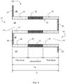
- One or more embodiments described herein relate to a catalyzed particulate filter comprising a plurality of porous walls extending longitudinally to form a plurality of parallel passages extending from an inlet end to an outlet end, wherein a quantity of the passages are inlet passages that are open at the inlet end and closed at the outlet end, and a quantity of passages are outlet passages that are closed at the inlet end and open at the outlet end, a first coating permeating through at least a portion of the porous walls of the particulate filter, wherein the length of porous wall permeated with the first coating is in the range of 1% to 80% of the wall length extending from the outlet end of the passages, and wherein the first coating is an oxidation catalyst comprising a platinum group metal; and a second coating permeating through at least a portion of the porous walls of the particulate filter, wherein the length of porous wall permeated with the second coating is in the range of 50% to 100% of the wall length extending from the
- the first selective catalytic reduction catalyst is a zeolitic framework material promoted with a metal selected from Cu, Fe, Co, Ni, La, Ce, Mn, V, Ag, and combinations thereof.
- the second coating permeates the porous walls of the particulate filter over essentially the entire length (e.g., 90-100% the entire length) of the porous walls of the particulate filter, and the first coating is intermingled with the second coating over 1% to 80% of the wall length extending from the outlet end of the passages.
- the first selective catalytic reduction catalyst comprises a molecular sieve promoted with a base metal, and wherein the length of the porous walls permeated only with the second coating forms a first catalytic zone, and the length of the porous walls permeated with both the first coating and second coating forms a second catalytic zone, wherein the oxidation catalyst intermingles with the first selective catalytic reduction catalyst in the second catalytic zone.
- the platinum group metal loading in the second catalytic zone is in the range of 3.5 g/m 3 (0.1 g/ft 3 ) to 1766 g/m 3 (50 g/ft 3 ).
- the length of porous wall permeated with the second coating is in the range of 50% to 80% of the wall length extending from the inlet end of the passages; wherein the length of porous wall that is permeated with the first coating but not permeated with the second coating is in the range of 20% to 50% of the wall length extending from the outlet end of the passages; and wherein the length of porous wall permeated with the second coating and having an overlapping first coating is in the range of 5% to 60% of the wall length, where the first coating is coated onto the surface of the overlapping portion of the porous wall permeated with the second coating.
- the porosity of the porous walls is in the range of 40% to 75%, and the mean pore size of the porous walls is in the range of 10 ⁇ m to 30 ⁇ m; and the first selective catalytic reduction catalyst comprises a copper or iron promoted CHA structure type molecular sieve.
- the third coating in certain embodiments may, for example, comprise a copper or iron promoted CHA structure type molecular sieve.
- a method of manufacturing a coated particulate filter according to claim 7 comprising introducing an oxidation catalyst comprising a plurality of particles into an outlet end of a plurality of parallel passages formed by a plurality of porous walls closed by a plug on an inlet end opposite the outlet end, wherein the particles of the oxidation catalyst permeates through at least a portion of the porous walls,; and introducing a first selective catalytic reduction catalyst comprising a plurality of particles into an inlet end of a plurality of parallel passages formed by a plurality of porous walls closed by a plug on an outlet side opposite the inlet side, wherein the particles of the first selective catalytic reduction catalyst permeates through the porous walls, wherein the first selective catalytic reduction catalyst is introduced into the inlet end of the plurality of parallel passages before the oxidation catalyst is introduced into the outlet end of the plurality of parallel passages, and the length of porous wall permeated with the first selective catalytic reduction catalyst is in the range of
- the porosity of the porous walls is in the range of 40% to 70%, and the mean pore size of the porous walls is in the range of 10 ⁇ m to 30 ⁇ m; wherein the oxidation catalyst further comprises at least one platinum group metal on the plurality of particles, and the plurality of particles of the oxidation catalyst have a composition of alumina, titania, zirconia, silica, silica/alumina, or a combination thereof; and wherein the first selective catalytic reduction catalyst is a molecular sieve promoted with a metal selected from Cu, Fe, Co, Ni, La, V, Mo, W, Mn, Ce, Ag and combinations thereof.
- the method further comprises coating a platinum group metal onto the filter such that it only covers the plug at the end of the outlet passages.
- the method further comprises impregnating the platinum group metal into the plurality of the alumina, titania, zirconia, silica, silica/alumina, or a combination thereof particles by an incipient wetness technique followed by thermally treating the impregnated particles at a temperature of 400°C to 600°C, wherein the loading of platinum group metal onto the length of porous wall permeated with the oxidation catalyst is in the range of 3.5 g/m 3 (0.1 g/ft 3 ) to 1766 g/m 3 (50 g/ft 3 ).
- the term "permeate" when used to describe the dispersion of the SCR catalyst and/or oxidation catalyst into the porous walls means that the particular composition penetrates into at least a majority of the hollow regions within the wall thickness, and becomes deposited on the internal surfaces throughout the thickness of the walls. In this manner the material becomes dispersed throughout the wall of the filter.
- the term "local loading" when used to describe the amount of catalytic material (e.g., PGM, SCR catalyst, oxidation catalyst) present on the porous walls means the average amount of catalytic material deposited on the walls within the particular zone or zones, that is the indicated loading is not averaged over the entire length of the substrate.
- a washcoat loading is defined in g/cm 3 (g/in 3 ), as the total weight of all washcoat components (i.e., PGM, refractory metal oxide support, zeolite, base metals, OSC, etc.) per unit volume of the monolithic substrate.
- PGM loading is defined in g/m 3 (g/ft 3 ), as the total weight of all PGM metals in the catalyst (e.g., Pt + Pd + Rh) per unit volume of the monolithic substrate. Therefore, TWC, DOC CSF and LNT catalysts that use PGM may be uniquely described with both washcoat loading and PGM loading, while SCR catalysts that do not have a PGM component may be described by only the washcoat loading.
- AMOx catalysts that have both SCR and PGM may be described by both criteria.
- loading for the PGM catalyst is the actual weight of PGM affixed to the internal and external surfaces of the porous wall(s) after the wash coat is applied
- loading for the SCR catalyst is the actual combined weight of metal promotor and molecular sieve material affixed to the internal and external surfaces of the porous wall(s) after the wash coat is applied.
- a localized PGM or washcoat loading may be used to specifically describe the weight/volume of the catalyst components in the specific catalyst zone.
- the SCR catalyst and/or oxidation catalyst may remain essentially on the surface of the porous filter walls.
- the term "essentially on the surface" when used to describe the dispersion of the SCR catalyst and/or oxidation catalyst on the porous walls means that at least a majority of the catalyst particles of the particular composition do not penetrate into regions within the wall thickness and become deposited on the internal surfaces throughout the thickness of the walls. Instead, the catalytic material becomes deposited on the outer surfaces of the walls, and a minority of the catalyst particles penetrates no further than 50% into hollow regions within the wall thickness, or no further than 33% into hollow regions within the wall thickness, or no further than 10% into hollow regions within the wall thickness.
- the penetration depth may be varied to optimize filter backpressure and interaction with catalyst components applied in separate washcoating steps, wherein the penetration depth may be in the range of 5% to 50% of the porous wall thickness, or in the range of 10% to 40%, or in the range of 5% to 20%, or in the range of 20% to 35%.
- the problem of balancing the several competing reactions may be addressed by the judicious selection and arrangement of catalytic materials and components in the exhaust stream, where the particulate matter (PM) can be reduced by the use of a porous wall particulate filter, oxides of nitrogen (NO x ) can be reduced with a selective catalytic reduction (SCR) catalyst utilizing a reductant (e.g., urea, NH 3 ), ammonia slip can be reduced by an ammonia oxidation catalyst (AMOx).
- a selective catalytic reduction (SCR) catalyst utilizing a reductant e.g., urea, NH 3
- AMOx ammonia oxidation catalyst
- Principles and embodiments of the present invention relate generally to multi-zone catalyzed filter articles and methods of manufacturing multi-zone catalyzed filter articles.
- the exhaust first passes through the SCR catalyst and then passes across the oxidation catalyst. If the exhaust bypasses the SCR catalyst and first is exposed to the oxidation function, then the reductant (e.g. NH 3 ) will be oxidized to NOx and the NOx abatement function will be compromised, even to the point of emitting greater NOx than the amount that entered the catalyst before the NH 3 is added as the reductant.
- the reductant e.g. NH 3
- Applicants have found a method for applying an SCR catalyst composition to a wall flow substrate to form a substrate that can be used in an application where high filtration efficiency is required.
- a substrate formed with this method is suitable for effectively removing particulate matter from exhaust (e.g., greater than 80%, or 90%, or 99%) in an emission treatment system.
- the coating method disclosed herein allows wall flow substrates to be loaded with practical levels of SCR catalyst without causing excessive back pressure across the coated article when implemented in emission treatment systems.
- the SCR catalyst is disposed throughout the wall of the filter along the entire length and permeates the whole cross-section of the wall. This allows for the SCR catalyst to permeate all filter pores and to spread over the maximum filter volume, thereby minimizing backpressure, and ensuring no by-passing of the SCR catalyst.
- the oxidation catalyst is dispersed throughout the wall of the filter along at least a portion of the length and permeates the whole cross-section of the wall. This allows the oxidation catalyst to permeate the filter pores and to spread over the maximum filter volume, thereby minimizing backpressure, and ensuring no by-passing of the oxidation catalyst.
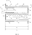
- the oxidation catalyst is dispersed throughout the wall of the filter along at least a portion of the length where the oxidation catalyst permeates the whole cross-section of the wall, and the oxidation catalyst is dispersed on the surface of the wall of the filter along at least a portion of the length where the oxidation catalyst does not permeate the whole cross-section of the wall. This allows the majority of the oxidation catalyst to reside primarily on the filter surface, and a minority of the catalyst particles penetrates no further than 50% into the wall thickness, or no further than 33% into the wall thickness, or no further than 10% into the wall thickness, along a portion of the filter wall length.
- the different zones are distinguished from each other by a change in the composition of the catalytic coating, a change in the loading of the catalytic coating, or both, when observed axially along the length of a porous wall.
- the oxidation catalyst is dispersed on top of the wall of the outlet channel(s) of the filter substrate. In various embodiments, the oxidation catalyst forms a layer on top of the wall over the SCR catalyst dispersed throughout the wall. The oxidative catalyst allows for some gas passage across the wall directly underneath it, providing that there is sufficient SCR catalyst in the wall to remove NOx prior to the gas crossing the oxidation catalyst.
- Embodiments of the invention are directed to catalyzed particulate filters comprising a plurality of longitudinally extending passages formed by longitudinally extending porous walls bounding and defining the passages and an axial length extending between an inlet end and an outlet end.
- the passages comprise inlet passages open at the inlet end and closed at the outlet end, and outlet passages being closed at the inlet end and open at the outlet end.
- outlet end and “outlet end” are in reference to the intended and accepted path of an exhaust gas through a catalytic article, where an untreated exhaust gas passes into a catalytic article at an inlet end, and a treated exhaust gas exits from an outlet end of the catalytic article.
- the outlet end of the catalytic article is opposite the inlet end.
- an SCR catalyst composition may be disposed within the porous walls and/or on the walls of the inlet passages extending from the inlet end and less than the full axial length of the wall flow filter, wherein the selective catalytic reduction catalyst comprises a molecular sieve and a transition metal, and an oxidation catalyst comprising a platinum group metal (PGM) is disposed throughout the wall of the filter and/or on the walls of the outlet passages extending from the outlet end and less than the full axial length of the wall flow filter.
- PGM platinum group metal
- a portion of the oxidation catalyst can permeate into the filter walls and be intermixed with the SCR catalyst.
- the catalyst applied to the inlet or outlet channels may form a thin washcoat layer over the inlet or outlet plugs, within the inlet or outlet channels.
- platinum group metal refers to platinum, palladium, rhodium, ruthenium, osmium, and iridium, or combinations thereof, and their oxides.
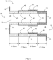
- Principles and embodiments of the present invention also relate to a catalyzed particulate filter comprising a substrate having porous walls and at least three catalytic zones formed by three catalytic coatings along the length of the porous walls.
- Principles and embodiments of the present invention relate to a catalyzed particulate filter comprising a substrate having porous walls and at least three catalytic zones along the length of the porous walls, where each of the at least three catalytic zones may comprise a first selective catalytic reduction catalyst, a platinum group metal oxidation catalyst, and a second selective catalytic reduction catalyst.
- the particulate filter comprises a plurality of porous walls having a length extending longitudinally to form a plurality of parallel passages extending from an inlet end to an outlet end, wherein a quantity of the passages are inlet passages that are open at the inlet end and closed at the outlet end, and a quantity of passages different from the inlet passages are outlet passages that are closed at the inlet end and open at the outlet end.
- the passages are closed with a plug, wherein the plug may have a length of about 0.64 cm long (about 1 ⁇ 4" long).
- the particulate filter has an inlet end into which gases may enter the inlet passages, and an outlet end from which gases may exit the outlet passages, where the gases pass from an inlet passage to an outlet passage by moving through the porous walls forming the parallel passages.
- the porous walls have a porosity in the range of 40% to 75%, or in the range of 40% to 60%, or in the range of 50% to 70%, or in the range of 50% to 65%, or in the range of 60% to 70%, or in the range of 55% to 65%. In various embodiments the porous walls have a porosity in the range of 60% to 65%.
- the mean pore size of the porous walls is in the range of 10 ⁇ m to 30 ⁇ m, or 10 ⁇ m to 25 ⁇ m, or 20 ⁇ m to 25 ⁇ m. In various embodiments, the mean pore size of the porous walls is in the range of 15 ⁇ m to 25 ⁇ m.
- At least three catalytic zones are formed along the wall length by catalytic material permeating the thickness of the porous walls over at least a portion of the wall length.
- the at least three catalytic zones include a first catalytic zone (also referred to as a first zone or first upstream zone) extending from the inlet end, a second catalytic zone (also referred to as a second zone) downstream from the first zone, and a third catalytic zone (also referred to as a third zone) downstream from the second zone.
- each of the zones is distinguished from the zone immediately upstream and/or downstream by a change in catalytic material composition, catalytic material loading, catalytic material placement on or in the wall(s), or combinations thereof.
- reference to a coating "extending from" an inlet end or an outlet end indicates that the coating starts at one end of the wall and progresses along the wall length towards the opposite end, or where a feature of the coating, such as being on the surface, may start a distance from the actual inlet opening
- reference to the coating feature "extending from” an inlet end or an outlet end indicates the coating feature progresses along the wall length towards the opposite end.
- a second zone between a first and third zone may include a coating on the surface that extends a percentage of the wall length from the inlet or outlet end, but does not start at the inlet or outlet end, can indicate the direction that the coating extends.
- catalytic material loading refers to a weight of material comprising one or more catalytically active component(s) deposited on and/or into the walls of a catalytic article, where the catalytically active components may be a platinum group metal (e.g., Pt, Pd, Rh), and/or a transition metal (e.g., Cu, Fe, Co, Ni, La, V, Mo, W, Mn, Ce, Ag).
- platinum group metal e.g., Pt, Pd, Rh
- transition metal e.g., Cu, Fe, Co, Ni, La, V, Mo, W, Mn, Ce, Ag.
- the catalytic material may further comprise a support material onto which the catalytically active component(s) are dispersed, and/or into which the catalytically active component(s) are impregnated, wherein the support material may be alumina, titania, zirconia, silica, silica/alumina, or a combination thereof.
- the first upstream zone may comprise a first selective catalytic reduction catalyst at a first loading.
- the first loading of the first selective catalytic reduction catalyst may be in the range of 0.006 g/cm 3 (0.1 g/in 3 ) to 0.18 g/cm 3 (3 g/in 3 ), or 0.03 g/cm 3 (0.5 g/in 3 ) to 0.15 g/cm 3 (2.5 g/in 3 ), or 0.03 g/cm 3 (0.5 g/in 3 ) to 0.12 g/cm 3 (2 g/in 3 ).
- the second zone may comprise a selective catalytic reduction catalyst at a first loading and either a platinum group metal oxidation catalyst at a first loading or the selective catalytic reduction catalyst at a second loading.
- the third zone may comprise a platinum group metal oxidation catalyst, and a selective catalytic reduction catalyst at one of a first loading and a second loading.
- the first catalytic zone is a first upstream zone extending from the inlet end of the substrate, the second zone is adjacent to and downstream from the first upstream zone, and the third zone is adjacent to and downstream from the second zone.
- the catalyzed particulate filter may further comprise a fourth zone adjacent to and extending downstream from the third zone.
- the fourth zone extends from 1% to 50% of the wall length from the third zone.
- the length of porous wall permeated with a first coating is in the range of 1% to 80%, or 1% to 70%, or 10% to 66% of the wall length extending from the outlet end of the passages
- the length of porous wall permeated with a second coating is in the range of 50% to 100%, or 50% to 80%, or 30% to 70% of the wall length extending from the inlet end of the passages.
- the length of porous wall permeated with the second coating is in the range of 50% to 80% of the wall length extending from the inlet end of the passages
- the length of porous wall permeated with a first coating is in the range of 1% to 70%.
- the second coating permeates the porous walls of the particulate filter over essentially the entire length of the porous walls of the particulate filter, and the first coating is intermingled with the second coating over 1% to 70% of the wall length extending from the outlet end of the passages.
- the second coating is a selective catalytic reduction catalyst comprising a molecular sieve and a metal.
- the selective catalytic reduction catalyst comprises a molecular sieve.
- the molecular sieve may have a zeolitic framework, and the zeolitic framework may have ring sizes no larger than 12.
- the zeolitic framework material comprises a double-six ring (d6r) unit.
- the zeolitic framework material may be selected from AEI, AFT, AFX, CHA, EAB, EMT, ERI, FAU, GME, JSR, KFI, LEV, LTL, LTN, MOZ, MSO, MWW, OFF, SAS, SAT, SAV, SBS, SBT, SFW, SSF, SZR, TSC, WEN, and combinations thereof.
- the zeolitic framework material may be selected from AEI, CHA, AFX, ERI, KFI, LEV, and combinations thereof.
- the zeolitic framework material may be selected from AEI, CHA, and AFX. In various embodiments, the zeolitic framework material is CHA. In one or more embodiments, the selective catalytic reduction catalyst further comprises a metal, which may be a base metal (e.g., wherein the SCR catalyst is in the form of a molecular sieve promoted with the metal).
- the selective catalytic reduction catalyst is promoted with a metal selected from Cu, Fe, Co, Ni, La, Ce, Mn, V, Ag, and combinations thereof. In various embodiments, the selective catalytic reduction catalyst is promoted with a metal selected from Cu, Fe, Ag, and combinations thereof. In various embodiments, the selective catalytic reduction catalyst is promoted with Cu and/or Fe.
- the zeolitic framework material is CHA promoted with copper or iron.
- the copper or iron promoted CHA structure type molecular sieve may be mixed with a plurality of platinum group metal impregnated alumina and/or silica/alumina particles to form a slurry.
- the selective catalytic reduction catalyst may be at a first loading or at a second loading, wherein the first loading may be in the range of 0.03 g/cm 3 (0.5 g/in 3 ) to 0.18 g/cm 3 (3 g/in 3 ), and the second loading may be in the range of 0.03 g/cm 3 (0.5 g/in 3 ) to 0.18 g/cm 3 (3 g/in 3 ), where the second loading may be the same or different from the first loading.
- the potential loading in an overlapping zone may be in the range of 0.06 g/cm 3 (1.0 g/in 3 ) to 0.3 g/cm 3 (5.0 g/in 3 ).
- the first loading of the first selective catalytic reduction catalyst on the first upstream zone may be in the range of 0.03 g/cm 3 (0.5 g/in 3 ) to 0.18 g/cm 3 (3 g/in 3 ), or in the range of 0.03 g/cm 3 (0.5 g/in 3 ) to 0.15 g/cm 3 (2.5 g/in 3 ), or in the range of 0.03 g/cm 3 (0.5 g/in 3 ) to 0.12 g/cm 3 (2 g/in 3 ).
- the first loading of the first selective catalytic reduction catalyst on the second zone may be in the range of 0.03 g/cm 3 (0.5 g/in 3 ) to 0.18 g/cm 3 (3 g/in 3 ), or in the range of 0.03 g/cm 3 (0.5 g/in 3 ) to 0.15 g/cm 3 (2.5 g/in 3 ), or in the range of 0.03 g/cm 3 (0.5 g/in 3 ) to 0.12 g/cm 3 (2 g/in 3 ).
- the first loading of the first selective catalytic reduction catalyst on the third zone may be in the range of 0.03 g/cm 3 (0.5 g/in 3 ) to 0.18 g/cm 3 (3 g/in 3 ), or in the range of 0.03 g/cm 3 (0.5 g/in 3 ) to 0.15 g/cm 3 (2.5 g/in 3 ), or in the range of 0.03 g/cm 3 (0.5 g/in 3 ) to 0.12 g/cm 3 (2 g/in 3 ).
- a non-limiting example of a selective catalytic reduction catalyst is a CHA zeolitic framework material promoted with copper having a silica to alumina molar ratio in the range of 10 to 100, more specifically, 10 to 75, and even more specifically 10 to 60.
- at least 0.03 g/cm 3 (0.5 g/in 3 ) of an SCR composition, or no more than 0.18 g/cm 3 (3 g/in 3 ) of an SCR composition, and in particular, 0.06 g/cm 3 (1.0 g/in 3 ) to 0.12 g/cm 3 (2.0 g/in 3 ), may be disposed on the porous walls of the filter.
- the first loading of a selective catalytic reduction catalyst in the second catalytic zone may be in the range of 0.03 g/cm 3 (0.5 g/in 3 ) to 0.12 g/cm 3 (2 g/in 3 ).
- the first coating is an oxidation catalyst comprising platinum, palladium, or a combination thereof.
- the oxidation catalyst is an ammonia oxidation catalyst.
- the PGM may be selected from platinum, palladium, rhodium, ruthenium, osmium, and iridium, or combinations thereof. In various embodiments, the PGM may be selected from platinum, palladium, or combinations thereof.
- the oxidation catalyst comprises at least one platinum group metal on a plurality of particles, and the plurality of particles of the oxidation catalyst may have a composition of alumina, titania, zirconia, silica, silica/alumina, or a combination thereof.
- the platinum group metal may be impregnated into the alumina, titania, zirconia, silica, and/or silica/alumina particles by the incipient wetness technique followed by a thermal treatment between 400°C and 600°C.
- the loading of platinum group metal onto the length of porous wall permeated with the slurry is in the range of 3.5 g/m 3 (0.1 g/ft 3 ) to 1766 g/m 3 (50 g/ft 3 ).
- the loading of platinum group metal onto the length of porous wall permeated with the slurry is in the range of 3.5 g/m 3 (0.1 g/ft 3 ) to 1766 g/m 3 (50 g/ft 3 ), or in the range of 35 g/m 3 (1 g/ft 3 ) to 1766 g/m 3 (50 g/ft 3 ).
- the platinum group metal loading in the second catalytic zone may be in the range of 3.5 g/m 3 (0.1 g/ft 3 ) to 1766 g/m 3 (50 g/ft 3 ), or in the range of 35 g/m 3 (1 g/ft 3 ) to 1766 g/m 3 (50 g/ft 3 ).
- the oxidation catalyst is a PGM slurry having a D90 ⁇ 3 microns, or a D90 ⁇ 5 microns, or a D90 ⁇ 10 microns, or D90 ⁇ 5-7 microns.
- a copper or iron promoted CHA structure type molecular sieve may be mixed with the oxidation catalyst slurry.
- Principles and embodiments of the present invention also relate to a method of manufacturing a catalyzed particulate filter article having at least three catalytic zones, wherein the at least three catalytic zones are formed using at least three catalytic coatings.
- An oxidation catalyst is introduced into an outlet end of a plurality of parallel passages formed by a plurality of porous walls closed by a plug on an inlet end opposite the outlet end, wherein the particles of the oxidative catalyst permeates through the porous walls, and wherein the length of porous wall permeated with the oxidation catalyst is in the range of 1% to 80% or in the range of 10% to 70%, or 60% to 70% of the wall length extending from the outlet end of the passages.
- a selective catalytic reduction catalyst comprising a plurality of particles is introduced into an inlet end of a plurality of parallel passages formed by a plurality of porous walls closed by a plug on an outlet side opposite the inlet side, wherein the particles of the selective catalytic reduction catalyst permeates through the porous walls, wherein the length of porous wall permeated with the particles of the selective catalytic reduction catalyst is in the range of 50% to 100%, or 50% to 80%, or 60% to 70% of the wall length extending from the inlet end of the passages.
- the oxidation catalyst may comprise a plurality of particles, for example, as a slurry of inorganic support material coated and/or impregnated with a PGM, wherein the oxidation catalyst may be an ammonia oxidation catalyst.
- a first selective catalytic reduction catalyst is introduced into the inlet end of the plurality of parallel passages before the oxidation catalyst is introduced into the outlet end of the plurality of parallel passages.
- the particles of the oxidation catalyst are interspersed with the particles of the selective catalytic reduction catalyst within the plurality of porous walls, wherein the particles of the selective catalytic reduction catalyst and the oxidation catalyst are interspersed on the surfaces and/or within the void space of the porous walls.
- the porosity of the porous walls is in the range of 60% to 65%.
- the length of porous wall permeated with the oxidation catalyst is in the range of 25% to 55% of the wall length extending from the outlet end of the passages.
- the length of porous wall permeated with the selective catalytic reduction catalyst is in the range of 50% to 80% of the wall length extending from the inlet end of the passages.
- the first selective catalytic reduction catalyst is introduced into the inlet end of the plurality of parallel passages before the oxidation catalyst is introduced into the outlet end of the plurality of parallel passages.
- the oxidation catalyst remains essentially on the surface of the overlapping portion of the porous wall without interspersing with the selective catalytic reduction catalyst, located within the porous walls.
- the second selective catalytic reduction catalyst is introduced into the outlet end of the plurality of parallel passages, wherein the second selective catalytic reduction catalyst permeates through the portion of the porous walls of the particulate filter not previously permeated with the first selective catalytic reduction catalyst, and may deposit essentially on the surface of the porous walls previously coated on the surface with an oxidation catalyst.
- the oxidation catalyst overlaps with the first selective catalytic reduction catalyst for at least a portion of the length of the porous walls.
- the particles of the oxidation catalyst are interspersed with the particles of the first selective catalytic reduction catalyst within the plurality of porous walls.
- the length of porous wall permeated with the particles of the selective catalytic reduction catalyst is in the range of 95% to 100% of the wall length extending from the inlet end of the passages
- the length of porous wall coated on the surface with the particles of the oxidation catalyst is in the range of 1% to 70% of the wall length extending from the outlet end of the passages.
- a selective catalytic reduction catalyst comprises a plurality of particles comprising a copper or iron promoted CHA structure type molecular sieve.
- a platinum group metal may be coated onto the exterior surface of a plug on the outlet side of the parallel passages.
- the platinum group metal may be coated onto the surfaces of the porous walls in the range of 5%, or no more than 5%, or no more than 3%, or no more than 2%, or no more than 1% of the wall length extending from the outlet end of the outlet passages, or no more than double the length of the plug.
- the substrate may be immersed vertically in a portion of a catalyst slurry of solid particles in a liquid such that the top of the substrate is located just above the surface of the slurry.
- the sample is left in the slurry for about 30 seconds.
- the substrate is removed from the slurry, and excess slurry is removed from the wall flow substrate first by allowing it to drain from the channels, then by blowing with compressed air (against the direction of slurry penetration).
- the SCR catalyst slurry may be deposited on and/or permeate into the porous walls of the filter, such that the pores are not occluded to the extent that undue back pressure will build up in the finished substrate.
- the oxidation catalyst slurry may be deposited on and/or permeate into the porous walls of the filter.
- a second SCR catalyst may be applied to the outlet channels to deposit on and/or permeates into the porous walls of the filter.
- a second oxidation catalyst may be applied to the inlet and/or outlet channels to deposit on the surface of the porous walls of the filter.
- FIGS. 1 and 2 illustrate a typical wall flow filter substrate 10 (also referred to as a wall flow filter) which has a plurality of passages 12. The passages are formed and tubularly enclosed by the internal walls 13 of the filter substrate.
- FIG. 1 depicts an external view of a wall flow filter substrate having an inlet end 14 and an outlet end 16. Alternate passages are plugged at the inlet end with inlet plugs 18 (shown in black), and at the outlet end with outlet plugs 20 to form opposing checkerboard patterns at the inlet 14 and outlet 16 ends of the substrate.
- the outlet plugs 20 have an interior surface 21 facing into the passage and an exterior surface 23 facing outward.
- FIG. 2 illustrates a cross-sectional view of plurality of porous walls extending longitudinally from an inlet end to an outlet end of a wall flow filter substrate.
- a partial cross-sectional view of a plurality of porous walls 13 extending longitudinally from an inlet end 14 to an outlet end 16, and forming a plurality of parallel passages 12 is shown.
- a gas stream 22 (shown as arrows) enters through the open, unplugged end of inlet passages 24, is stopped at the closed end by outlet plug 20, and diffuses through the porous walls 13 forming the passages to the outlet passages 26.
- the gas stream 22 exits the filter by flowing through the open, unplugged end of outlet passages 26, and is stopped at the closed end by inlet plug 18.
- the gas is prevented from flowing backwards to the inlet end of the filter from the outlet passages by the inlet plugs 18, and prevented from re-entering the inlet passages from the outlet end by the outlet plugs 20.
- a quantity of the passages are inlet passages that are open at the inlet end and closed at the outlet end, and a quantity of passages are outlet passages that are closed at the inlet end and open at the outlet end, where the outlet passages are different passages than the inlet passages.
- FIG. 3 illustrates a magnified view of a cross-section of a plurality of porous walls of a wall flow filter substrate having a plurality of zones.
- the catalyst article shown comprises a wall flow filter 10 having a plurality of longitudinally extending passages 12 formed by longitudinally extending porous walls 13 bounding and defining the passages 24 and 26, where the walls have an axial length 'L W ' extending between an inlet end 14 and an outlet end 16 of the wall flow filter having a length 'L F '.
- filter length 'L F ' ⁇ axial wall length 'L W '.
- the porous walls have substantially uniform porosity throughout.
- the passages 24 and 26 comprise inlet passages 24 which are open at the inlet end 14 and closed at the outlet end 16, and outlet passages 26 which are closed at the inlet end 14 and open at the outlet end 16.
- a catalytic substrate may be configured to have at least three catalytic zones, wherein the catalytic zones are distinguished from each other by the spatial arrangement of three or more catalytic components.
- At least three catalytic zones 30, 32, 34 are formed by at least three catalytic coatings along the length 'L W ' of the porous walls 13, wherein the coating(s) may permeate the thickness of the porous walls 13.
- the at least three catalytic coatings are disposed along the length 'L W ' of the porous walls 13 in different spatial arrangements.
- the different zones may be distinguished from each other by a change in the composition of the catalytic coating, a change in the loading of the catalytic coating, a change in the combination of one or more catalytic coatings, or any combination thereof, along the length of a porous wall.
- a first zone 30 extends axially from the inlet end 14 of the porous walls 13 a distance less than the full length of the porous wall and a second zone 32 extends axially from the first zone 30 a distance less than the distance to the outlet end 16 of the porous wall 13.
- a first zone 30 comprises or consists essentially of the first SCR catalyst coating
- a second zone 32 comprises or consists essentially of the platinum group metal coating and the first SCR catalyst coating.
- a third zone 34 extends axially from the second zone 32 to the outlet end 16 of the porous wall(s) 13.
- the third zone 34 comprises or consists essentially of a platinum group metal coating and a second SCR catalyst coating.
- the first zone 30 may comprise an SCR catalyst to reduce the oxides of nitrogen (NO x ) in an exhaust gas
- the second zone 32 may comprise an ammonia oxidation (“AMOx”) catalyst to prevent ammonia (NH 3 ) used with the SCR catalyst from exiting the catalytic substrate in the exhaust stream, and/or a diesel oxidation catalyst ("DOC") to reduce the amount of carbon monoxide (“CO”) and unburned hydrocarbons (“HC”) components in the exhaust gas
- the third zone may comprise an AMOx and/or DOC catalyst and a second SCR catalyst to reduce or eliminate NO x remaining in the exhaust gas or produced by oxidation of the NH 3 by the oxidation catalysts, and the porous walls of the catalytic substrate reduce or eliminate the particulate matter (PM) in the exhaust gas.
- AMOx ammonia oxidation
- DOC diesel oxidation catalyst
- the third zone may comprise an AMOx and/or DOC catalyst and a second SCR catalyst to reduce or eliminate NO x remaining in the
- Reference to a zone that consists essentially of a specified coating within this application, means only the specified coating was intentionally deposited within the specified zone, and while other components may inadvertently deposit or migrate into the zone, the majority of material in the zone is the specifically deposited material.
- FIG. 4 illustrates a magnified view of a cross-section of an exemplary embodiment of a plurality of porous walls of a wall flow filter substrate having a plurality of zones. While FIG. 4 may depict the coatings occupying a portion of the thickness of the porous walls in the zones, this is only as a representation and in various embodiments the coatings may permeate throughout the thickness of the porous wall, or penetrate a distance into the porous wall depending upon the viscosity of the coating(s) and/or particle and pore sizes.
- a first zone 30 may extend axially from the inlet end 14 of the porous wall 13, where the first zone may extend a distance from the inlet end 14 of the porous wall 13 less than the full length of the porous wall 13.
- the first zone 30 may comprise a first selective catalytic reduction (SCR) catalyst 40 at a first loading.
- the first selective catalytic reduction catalyst first loading 41 may be in the range of 0.03 g/cm 3 (0.5 g/in 3 ) to 0.18 g/cm 3 (3 g/in 3 ), or 0.03 g/cm 3 (0.5 g/in 3 ) to 0.15 g/cm 3 (2.5 g/in 3 ), or 0.03 g/cm 3 (0.5 g/in 3 ) to 0.12 g/cm 3 (2 g/in 3 ).
- a second zone 32 downstream of the first zone 30 may extend axially at least a portion of the length of the plurality of porous walls 13, where the second zone may extend a distance from the first zone less than the length of the porous walls 13 to the outlet end 16 of the porous walls 13.
- the second zone 32 comprises a first selective catalytic reduction catalyst 40 at a first loading and a platinum group metal oxidation catalyst 45 at a first loading 46.
- the platinum group metal oxidation catalyst 45 is disposed within at least a portion of the length of the plurality of porous walls 13, and on at least a length of the walls 13 of the outlet passages 26 extending from the outlet end 16 for less than the axial length 'L W ' of the wall flow filter walls.
- the first selective catalytic reduction catalyst 40 may have the same or a different composition than the second selective catalytic reduction catalyst 43.
- the second SCR loading may be in an amount that is the same as or different from the first SCR loading.
- the first SCR catalyst coating and the second catalyst coating may each comprise a molecular sieve with a zeolitic framework material selected from AEI, CHA, and AFX, where the first SCR catalyst and the second catalyst may be independently promoted with a metal selected from Cu, Fe, Co, Ni, La, Ce, Mn, V, Ag, or combinations thereof.
- the first selective catalytic reduction catalyst 40 may have the same or a different composition than the second selective catalytic reduction catalyst 43.
- the second SCR loading may be in an amount that is the same as or different from the first SCR loading.
- the platinum group metal oxidation catalyst first loading 46 may be in the range of 18 g/m 3 (0.5 g/ft 3 ) to 1766 g/m 3 (50 g/ft 3 ).
- the second zone comprises an ammonia oxidation catalyst (AMOx).
- AMOx ammonia oxidation catalyst
- a third zone 34 downstream of the second zone 32 may extend the length of the porous walls 13 from the second zone 32 to the outlet end of the porous walls 13.
- An oxidation catalyst 45 is disposed within at least a portion of the length of the plurality of porous walls 13, and on at least a length of the of the surface of the walls 13 of the outlet passages 26 extending from the outlet end 16 for less than the axial length 'L W ' of the wall flow filter walls.
- the oxidation catalyst 45 may be on the walls 13 as opposed to permeating the walls, however, a portion of the oxidation catalyst 45 may penetrate a depth into the wall(s) 13 less than the thickness of the wall(s) 13, but the majority of the oxidation catalyst 45 is on or upon the wall, and not embedded in the wall.
- FIG. 5 illustrates a magnified view of a cross-section of a plurality of porous walls of a wall flow filter substrate having a plurality of zones formed by a plurality of coatings.
- a first zone 30 may extend axially from the inlet end 14 of the porous wall 13, where the first zone may extend a distance from the inlet end 14 of the porous wall 13 less than the full length of the porous wall 13.
- the first zone 30 comprises a first selective catalytic reduction (SCR) catalyst 40 at a first loading.
- the first selective catalytic reduction catalyst first loading may be in the range of 0.03 g/cm 3 (0.5 g/in 3 ) to 0.18 g/cm 3 (3 g/in 3 ), or in the range of 0.03 g/cm 3 (0.5 g/in 3 ) to 0.15 g/cm 3 (2.5 g/in 3 ), or in the range of 0.03 g/cm 3 (0.5 g/in 3 ) to 0.12 g/cm 3 (2 g/in 3 ).
- a second zone 32 downstream of the first zone 30 may extend axially at least a portion of the length of the plurality of porous walls 13, where the second zone may extend a distance from the first zone less than the length of the porous walls 13 to the outlet end 16 of the porous walls 13.
- the second zone 32 may comprise a first selective catalytic reduction catalyst 40 at a first loading and a platinum group metal oxidation catalyst 45 at a first loading 46.
- the second zone 32 may comprise a second selective catalytic reduction catalyst 43 at a second loading and a platinum group metal oxidation catalyst 45 at a first loading 46.
- the platinum group metal oxidation catalyst first loading 46 may be in the range of 18 g/m 3 (0.5 g/ft 3 ) to 1766 g/m 3 (50 g/ft 3 ), or in the range of 35 g/m 3 (1.0 g/ft 3 ) to 353 g/m 3 (10 g/ft 3 ), or in the range of 88 g/m 3 (2.5 g/ft 3 ) to 177 g/m 3 (5 g/ft 3 ).
- a third zone 34 downstream of the second zone 32 may extend the length of the porous walls 13 from the second zone 32 to the outlet end of the porous walls 13.
- the third zone 34 may comprise a first selective catalytic reduction catalyst 40 at one of the first loading and the second selective catalytic reduction catalyst 43 at a second loading, and the platinum group metal oxidation catalyst 45 at the first loading 46.
- the selective catalytic reduction catalyst second loading 42 may be in the range of 0.03 g/cm 3 (0.5 g/in 3 ) to 0.18 g/cm 3 (3 g/in 3 ), or in the range of 0.03 g/cm 3 (0.5 g/in 3 ) to 0.15 g/cm 3 (2.5 g/in 3 ), or in the range of 0.03 g/cm 3 (0.5 g/in 3 ) to 0.12 g/cm 3 (2 g/in 3 ).
- FIG. 6 illustrates a magnified view of a cross-section of another exemplary embodiment of a plurality of porous walls of a wall flow filter substrate having a plurality of zones formed by another arrangement of a plurality of coatings.
- a first zone 30 may extend axially from the inlet end 14 of the porous wall 13, where the first zone may extend a distance from the inlet end 14 of the porous wall 13 less than the full length of the porous wall 13.
- the first zone 30 comprises a first selective catalytic reduction (SCR) catalyst 40 at a first loading.
- the first selective catalytic reduction catalyst first loading may be in the range of 0.03 g/cm 3 (0.5 g/in 3 ) to 0.18 g/cm 3 (3 g/in 3 ), or in the range of 0.03 g/cm 3 (0.5 g/in 3 ) to 0.15 g/cm 3 (2.5 g/in 3 ), or in the range of 0.06 g/cm 3 (1.0 g/in 3 ) to 0.12 g/cm 3 (2.0 g/in 3 ).
- a second zone 32 downstream of the first zone 30 may extend the length of the porous walls 13 from the first zone less than the length of the porous walls 13 to the outlet end 16 of the porous walls 13.
- the second zone 32 may comprise a first selective catalytic reduction catalyst 40 at one of the first loading and the second selective catalytic reduction catalyst 43 at a second loading, and the platinum group metal oxidation catalyst 45 at the first loading 46.
- an SCR catalyst composition may be disposed within at least a portion of the length of the plurality of porous walls 13 and permeate through the porous wall over about 1% to about 98% of the wall length.
- the second selective catalytic reduction catalyst 43 at a first loading may be in the range of 0.018 g/cm 3 (0.3 g/in 3 ) to 0.18 g/cm 3 (3 g/in 3 ), or in the range of 0.024 g/cm 3 (0.4 g/in 3 ) to 0.15 g/cm 3 (2.5 g/in 3 ), or in the range of 0.03 g/cm 3 (0.5 g/in 3 ) to 0.12 g/cm 3 (2 g/in 3 ).
- a third zone 34 downstream of the second zone 32 may extend the length of the porous walls 13 from the second zone 32 to the outlet end of the porous walls 13.
- the third zone 34 may comprise a second selective catalytic reduction catalyst 43 at a second loading, and the platinum group metal oxidation catalyst 45 at the first loading 46.
- the second selective catalytic reduction catalyst 43 first loading may be in the range of 0.018 g/cm 3 (0.3 g/in 3 ) to 0.18 g/cm 3 (3 g/in 3 ), or in the range of 0.024 g/cm 3 (0.4 g/in 3 ) to 0.15 g/cm 3 (2.5 g/in 3 ), or in the range of 0.03 g/cm 3 (0.5 g/in 3 ) to 0.12 g/cm 3 (2 g/in 3 ), or in the range of 0.03 g/cm 3 (0.5 g/in 3 ) to 0.18 g/cm 3 (3 g/in 3 ).
- the composition of the first selective catalytic reduction catalyst 40 and the second selective catalytic reduction catalyst 43 may be the same or different, for example, the first selective catalytic reduction catalyst 40 composition may be Cu-CHA at a first loading of 0.15 g/cm 3 (2.5 g/in 3 ), and the second selective catalytic reduction catalyst 43 composition may be Fe-ZSM-5 at a first loading of 0.12 g/cm 3 (2.0 g/in 3 ).
- the first selective catalytic reduction catalyst 40 composition may be Cu-CHA at a first loading of 0.18 g/cm 3 (3.0 g/in 3 ), and the second selective catalytic reduction catalyst 43 composition may be Cu-CHA at a first loading of 0.12 g/cm 3 (2.0 g/in 3 ).
- FIG. 7 illustrates a magnified view of a cross-section of a plurality of porous walls of a wall flow filter substrate depicting four zones.
- at least four catalytic zones are formed by at least three catalytic coatings along the length 'L W ' of the porous walls 13.
- a first zone 30 extends axially from the inlet end 14 of the porous walls 13 a distance less than the full length of the porous wall 13
- a second zone 32 extends axially from the first zone 30 a distance less than the distance to the outlet end 16 of the porous wall(s) 13
- a third zone 34 extends axially from the second zone 32 a distance less than the distance to the outlet end 16 of the porous wall(s) 13
- a fourth zone 36 extends axially from the third zone 34 to the outlet end 16 of the porous wall(s) 13.
- the at least three catalytic coatings are disposed along the length 'L W ' of the porous walls 13 in different spatial arrangements.
- four catalytic coatings are disposed along the length 'L W ' of the porous walls 13 in different spatial arrangements.
- the first zone consists essentially of the first SCR catalyst coating; and the second zone comprises the platinum group metal coating, and the first or the second SCR catalyst coating.
- the platinum group metal is present in the second zone at a loading in the range of 35 g/m 3 (1 g/ft 3 ) to 1766 g/m 3 (50 g/ft 3 ).
- the third zone consists essentially of the first SCR catalyst coating, the second SCR catalyst coating, and the platinum group metal coating; and the fourth zone comprises the platinum group metal coating and the second SCR catalyst coating.
- the platinum group metal is present in the third and fourth zones at a loading in the range of 35 g/m 3 (1 g/ft 3 ) to 1766 g/m 3 (50 g/ft 3 ).
- a first zone 30 may extend from the inlet end 14 of the wall 13, and is upstream of subsequent zones.
- the first zone 30 may comprise a selective catalytic reduction catalyst 40 at a first loading.
- An SCR catalyst composition is disposed within at least a portion of the length of the plurality of porous walls 13 and permeates through the porous wall over that portion of the wall length.
- a second zone 32 downstream of the first zone 30 may extend at least a portion of the length of the plurality of porous walls 13 from the first zone and less than the full length of the walls 13 to the outlet end 16 of the porous walls 13.
- the second zone 32 may comprise a selective catalytic reduction catalyst 40 at a first loading and a platinum group metal oxidation catalyst 45 at a first loading 46, or a selective catalytic reduction catalyst 40 at a second loading 42 and a platinum group metal oxidation catalyst 45 at a first loading 46.
- the second loading may be in an amount that is the same as or different from the first loading.
- a third zone 34 downstream of the second zone 32 may extend at least a portion of the length of the plurality of porous walls 13 from the second zone, and less than the length of the wall 13 to the outlet end 16 of the porous walls 13.
- the third zone 34 may comprise a first selective catalytic reduction catalyst at one of the first loading and/or the second loading 42, and the platinum group metal oxidation catalyst 45 at the first loading 46.
- the third zone 34 may comprise a first selective catalytic reduction catalyst at a first loading and a platinum group metal oxidation catalyst 45 at a first loading 46, or a selective catalytic reduction catalyst at a second loading 42 and a platinum group metal oxidation catalyst 45 at a first loading 46.
- the second loading 42 may be in an amount that is the same as or different from the first loading.
- the oxidation catalyst 45 may be on the walls 13 in the third zone as opposed to permeating the walls, however, a portion of the oxidation catalyst 45 may penetrate a depth into the wall(s) 13 less than the thickness of the wall(s) 13, but the majority of the oxidation catalyst is on or upon the wall, and not embedded within the wall.
- a fourth zone 36 downstream of the third zone 34 may extend the length of the porous walls 13 from the third zone 34 to the outlet end of the porous walls 13.
- the fourth zone 34 may comprise a selective catalytic reduction catalyst 40 at one of the first loading and/or the second loading 42, and the platinum group metal oxidation catalyst 45 at the first loading 46.
- a first zone 30 may extend axially from the inlet end 14 of the porous wall 13, where the first zone may extend a distance from the inlet end 14 of the of the porous wall 13 less than the full length of the porous wall 13.
- the first zone 30 may comprise a first selective catalytic reduction (SCR) catalyst 40 at a first loading.
- the first selective catalytic reduction catalyst first loading may be in the range of 0.03 g/cm 3 (0.5 g/in 3 ) to 0.18 g/cm 3 (3 g/in 3 ).
- At least one catalytic coating permeates the thickness of the porous walls 13.
- a first SCR catalytic coating permeates the thickness of the porous walls 13, wherein the SCR catalytic coating permeates at least a first zone.
- a first SCR catalytic coating and a first PGM catalytic coating a permeates the thickness of the porous walls 13, wherein the SCR catalytic coating and PGM catalytic coating permeates at least a second zone.
- FIG. 8 (not according to the invention) illustrates a magnified view of a cross-section of a plurality of porous walls of a wall flow filter substrate having four zones formed by at least three coatings.
- a first zone extends axially from the inlet end of the porous walls a distance less than the full length of the porous wall 13 and consists essentially of the first SCR catalyst coating 40; and a second zone extends axially from the first zone a distance less than the distance to the outlet end of the porous wall an comprises the first SCR catalyst coating 40 and the second SCR catalyst coating 43; and a third zone extends axially from the second zone a distance less than the distance to the outlet end of the porous wall and consists essentially of the first SCR catalyst coating 40, the second SCR catalyst coating 43, and the platinum group metal coating 45; and the fourth zone extends axially from the third zone to the outlet end of the porous wall and comprises a combination or mixture 49 of the platinum group metal coating 45 and the second SCR catalyst coating 43.
- the combination 49 may be formed by introducing the second SCR catalyst and oxidation catalyst particles sequentially into the outlet end of the particulate filter channels.
- FIG. 9 illustrates a magnified view of a cross-section of a plurality of porous walls of a wall flow filter substrate having one or more catalyst(s) on the surface of the walls in one or more zones, where the catalysts may form sandwiched layers.
- the catalyzed particulate filter 10 may comprise three catalytic zones or four catalytic zones.
- the first zone may comprise a first SCR catalyst 40 at a first loading that permeates a length of the porous walls in the range of 5% to 50% of the wall length extending from the inlet end of the passages, and an oxidative catalyst 47 at a first loading 48 that coats the surface of the walls in the first zone.
- a second zone may comprise a first SCR catalyst 40 at a first loading that permeates a length of the porous walls in the range of 5% to 50% of the wall length extending from the first zone, where the first zone ends at the interface where the second zone begins, and a second selective catalytic reduction catalyst 43 at a first loading that coats the surface of the walls in the second zone extending from the first zone upstream from the second zone.
- a third zone may comprise a first SCR catalyst 40 at a first loading that permeates a length of the porous walls in the range of 5% to 50% of the wall length extending from the second zone, an oxidative catalyst 45 at a first loading 46 that coats the surface of the walls in the third zone, and a second selective catalytic reduction catalyst 43 at a first loading that covers the oxidation catalyst 45.
- a fourth zone may comprise a combination 49 of catalyst compositions including an oxidative catalyst 45 at a first loading 46 and a second SCR catalyst 43 at a first loading that permeates a length of the porous walls in the range of 5% to 50% of the wall length extending from the third zone to the outlet end, where the third zone ends at the interface where the fourth zone begins, and an oxidative catalyst at a first loading 46 that permeates the walls in the fourth zone extending from the third zone to the outlet, where the oxidation catalyst is interspersed with the SCR catalyst within the porous walls.
- the catalyzed particulate filter may comprise more than four catalytic zones by reducing the length of one or more of the four individual zones, and/or incorporating additional catalytic material as additional coatings applied from the filter inlet into the porous walls and/or on the walls surfaces.
- the additional zones may be downstream of the fourth zone.
- FIG. 10 illustrates a magnified view of a cross-section of a plurality of porous walls of a wall flow filter substrate having a catalyst at least on the surface of the walls in a zone, where the catalysts may form sandwiched layers.
- the catalyzed particulate filter 10 may comprise four catalytic zones.
- the first zone may comprise a first SCR catalyst 40 at a first loading that permeates a length of the porous walls in the range of 5% to 50% of the wall length extending from the inlet end of the passages.
- a second zone may comprise a first SCR catalyst 40 at a first loading that permeates a length of the porous walls in the range of 5% to 50% of the wall length extending from the first zone, where the first zone ends at the interface where the second zone begins, and an oxidative catalyst 45 at a first loading 46 that coats the surface of the walls in the second zone extending from the first zone upstream from the second zone.
- a third zone may comprise a first SCR catalyst 40 at a first loading that permeates a length of the porous walls in the range of 5% to 50% of the wall length extending from the second zone, an oxidative catalyst 45 at a first loading 46 that coats the surface of the walls in the third zone, and a second selective catalytic reduction catalyst 43 at a first loading that covers the oxidation catalyst 45, wherein the oxidative catalyst 45 is sandwiched between the first SCR catalyst 40 and the second SCR catalyst 43.
- a fourth zone may comprise a combination 49 of catalyst compositions including an oxidative catalyst 45 at a first loading 46 and a second SCR catalyst 43 at a first loading that permeates a length of the porous walls in the range of 5% to 50% of the wall length extending from the third zone to the outlet end, where the third zone ends at the interface where the fourth zone begins, and an oxidative catalyst at a first loading 46 that permeates the walls in the fourth zone extending from the third zone to the outlet, where the oxidation catalyst is interspersed with the SCR catalyst within the porous walls.
- the combination 49 may be formed by a mixed slurry of SCR and oxidation catalyst particles introduced into the outlet end of the particulate filter channels.
- FIG. 11 illustrates a magnified view of a cross-section of a plurality of porous walls of a wall flow filter substrate having a catalyst at least on the surface of the walls of a front zone.
- An exhaust gas stream 22 enters the inlet passages 24 and flows toward the outlet end 16 of the wall flow filter 10.
- the gas can take multiple paths 54,56,58 through the filter 10, including passing through 54 the porous walls 13 from the inlet passages 24 to the outlet passages 26, where it can exit via the outlet end 16 of the filter.
- some of the exhaust gas 22 can follow pathway 54 through the porous filter wall 13 containing the SCR catalyst 40 and then contact the oxidation catalyst 45 as it exits the filter.
- some of the exhaust gas 22 can diffuse through the porous wall 13 containing the SCR catalyst 40 and through the oxidation catalyst 45.
- a platinum group metal coating 51 may be coated onto the interior surface of the outlet passages 26 near the outlet 16 of the parallel passages. The platinum group metal coating 51 may extend into the outlet end of the outlet passages 26 5% or less of the wall length, or 3% or less of the wall length, or 1% or less of the wall length. The platinum group metal coating 51 may extend into the outlet end of the outlet passages 26 a length in the range of 1 mm to 2.5 mm.
- FIG. 12 illustrates a magnified view of a cross-section of a plurality of porous walls of a wall flow filter substrate having a plug coating on the exterior surface of the outlet plugs.
- the porous filter wall 13 containing the SCR catalyst 40 may have one or more additional coatings impregnated into the porous filter wall 13 and/or coated onto the surface of the porous filter wall 13, as described herein, and may further comprise a plug coating on the exterior surface 23 of a plug 20 at the closed outlet end of the inlet passages 24, wherein the plug coating comprises a platinum group metal, and where the plug coating may wrap around the corner of the porous walls.
- FIG. 13 illustrates a magnified view of a cross-section of a plurality of porous walls of a wall flow filter substrate having a plurality of zones formed by a plurality of coatings, wherein at least some catalytic coatings may be on the surface of the porous walls of the wall flow filter.
- Each of the catalytic components permeates the porous walls of the catalytic substrate and are interspersed within the walls.
- the SCR catalyst is intermixed with the PGM catalyst within the porous walls.
- the SCR catalyst permeates the porous walls and the majority of PGM catalyst resides on the surface of the SCR impregnated porous walls.
- the majority of PGM catalyst resides on the surface of the SCR impregnated porous walls and is sandwiched between the SCR catalyst permeated porous walls and an overlayer of SCR catalyst.
- the platinum group metal coating in the second zone is on the surface of the porous walls; and the platinum group metal coating in the third zone is sandwiched between the first SCR catalyst coating and the second SCR catalyst coating.
- FIG. 14 illustrates an engine system comprising an emission treatment system 140 and a urea injector comprising an ammonia precursor feed line 148, an air feed line 149, and a mixing station 146 connected to an in fluid communication with the emission treatment system.
- the exhaust containing gaseous pollutants including unburned hydrocarbons, carbon monoxide and NOx
- particulate matter is conveyed from the engine 141 through a connector 142 to a catalyzed particulate filter 143, as described herein. After the catalyzed particulate filter 143, the exhaust gas exits the system via the tailpipe 144.
- a reductant for example urea
- a reductant for example urea
- Aqueous urea shown on one line 148 may serve as the ammonia precursor which can be mixed with air on another line 149 in a mixing station 146.
- Valve 145 can be used to meter precise amounts of aqueous urea which are converted in the exhaust stream to ammonia.
- the exhaust stream with the added ammonia is conveyed to the multifunctional, catalyzed particulate filter 143, where the NH 3 can interact with an SCR catalyst.
- the connector 142 may not be required when no additional components are used before the catalyzed particulate filter 143.
- the catalyzed particulate filter 143 is coupled directly to the engine 141.
- the distance between the engine and catalyst can be quite short resulting in a so-called “close coupled” catalytic arrangement.
- the distance from the engine to the catalyst can be longer, resulting in an "underfloor” configuration.
- FIG. 15 illustrates an engine system comprising an emission treatment system, a urea injector, and other engine components.
- the treatment system includes one or more separate components 147.
- These optional components 147 can include one or more of a diesel oxidation catalyst, lean NOx trap, partial NOx adsorber or three-way catalyst.
- additional SCR catalyst 150 can be disposed upstream of the multifunctional catalyzed particulate filter 143.
- the additional SCR catalyst may be disposed on a monolithic, honeycomb flow through substrate or ceramic foam substrate upstream of the soot filter.
- additional SCR catalyst 152 can be disposed downstream of the multifunctional catalyzed particulate filter 143, and may also contain an additional AMOx catalyst. Even in these various systems, the use of the multifunctional coated SCR soot filter still achieves a reduction in the total volume of catalyst required to meet NOx reduction goals.
- additional oxidation catalysts can be disposed upstream of exhaust component 147 or downstream with exhaust component 152.
- Non-limiting Examples 1 to 7 are summarized in Table 1.
- the blank filter substrate is a SiC filter segment (34 mm x 34 mm x 150 mm) with 63% porosity and a mean pore size of 23 ⁇ m.
- the SCR catalyst is copper exchanged chabazite zeolite (Cu-CHA) with CuO loading of 3.25% and SiO 2 /Al 2 O 3 molar ratio of 30.
- Cu-CHA was dispersed in water with 1% Cu acetate and 5% Zr acetate.
- the slurry was milled until 90% of the particles had a size less than 5 ⁇ m, and the slurry content was adjusted to 23% solids.
- the slurry was washcoated onto the filter substrate by immersing the substrate into the slurry with the inlet end of the substrate down into and the outlet end just above (about 0.64 cm (about 1 ⁇ 4 inch)) the slurry level.
- the substrate was pulled out of the slurry, and a stream of air was blown from the outlet side of the channels until no washcoat slurry was coming out from the inlet side.
- the coated sample was then dried at 110°C for 2 hours and calcined in air at 450°C for 1 hour.
- a pre-milled SiO 2 /Al 2 O 3 powder (wherein 90% of the particles are less than 5 ⁇ m) was suspended in water to provide a slurry with about 40% solids.
- a calculated amount of platinum ammine solution (to achieve the desired final Pt content) was added into the suspension drop-wise while stirring.
- the resulting slurry was further diluted with water to achieve about 5% solids by weight.
- the Pt slurry was coated from the outlet end by immersing the filter substrate outlet into the slurry at a pre-marked position so that the coating coverage reached to a pre-determined level.
- the substrate was pulled out of the slurry, and a stream of air was blown from the inlet side of the channels until no washcoat slurry was coming out from the outlet side.
- the coated sample was then dried at 110°C for 2 hours and calcined in air at 450°C for 1 hour.
- a coated filter was further coated with a supplemental Cu-CHA slurry from the outlet end with a precalculated solid content and a predetermined coverage.
- Samples 1 to 7 of Examples 1 to 7 the evaluation was conducted with a laboratory reactor which is capable of flowing 150 liter of gas per minute.
- the sample was housed in the center of a heated sample holder.
- the targeted temperature of the CSF inlet was achieved partially from the preheated gas via a preheater and partially by the heated sample holder itself.
- the SCR reaction and CO oxidation were evaluated separately.
- the SCR feed consists of 500 ppm NO, 550 ppm NH 3 , 10% O 2 , 5% H 2 O, 5% CO 2 and balance N 2 .
- the gas hourly space velocity (GHSV) was 60,000/h.
- the temperature was ramped from 200 to 500°C at a ramp rate of 2.5°C/min.
- each catalyzed filter was thermally aged at 800°C for 16 hours with a feed consisting of 10% O 2 , 10% H 2 O and 80% N 2 .
- Table 2A shows the NO x conversion for Samples 1 to 7. At lower temperatures (200-300°C), all 2-coat and 3-coat samples have higher NO x conversions compared to the SCR reference (Sample 1). At 500°C, some samples show higher or comparable NO x conversion (Samples 3 and 5), but others show lower NO x conversions (Sample 2, 4, 6, and 7).
- Table 2B compares the NH 3 conversions for Samples 1 to 7. All samples (Samples 2 to 7) show comparable or higher NH 3 conversions than the reference (Sample 1), especially at higher temperatures.
- Table 2C shows the peak N 2 O formation during the SCR test and CO conversion at 600°C for Samples 1 to 7.
- Table 2A NO x Conversion (%) for Samples 1 to 7 Sample ID 200°C 300°C 400°C 500°C 1 24 83 84 80 2 26 87 85 78 3 25 86 87 83 4 26 86 83 73 5 31 89 89 80 6 29 83 81 72 7 29 88 85 77
- Table 2B NH 3 Conversion (%) for Samples 1 to 7 Sample ID 200°C 300°C 400°C 500°C 1 20 72 77 85 2 22 77 85 94 3 20 75 82 91 4 21 77 88 95 5 26 79 85 95 6 22 79 85 93 7 23 79 85 94
- Table 2C Peak N 2 O Formation and CO Conversion at 600°C Samples 1 to 7 Sample ID Peak N 2 O formation (ppm) N 2 O peak temperature (°C) CO conversion at 600°C (%) 1 10 297 12 2 13 346 22 3 11 283 19 4 15 348 24 5 13 271 25 6 27 261 34 7 16 263 33
- Non-limiting Examples 8 to 11 are summarized in Table 3. All these examples are 3-coat examples with the same catalyst slurries. These Examples can be considered as variations of Example 7, wherein the variation derives from the individual coating length of each catalyst coating on the substrate.
- Table 4 is an analysis of the resulting zoning of Samples 7 to 11. By changing the coating coverage, either 3 or 4 zoned catalyzed filters can be created due to changes in the overlap of the coatings.
- the materials, slurry preparation and coating methodology are the same as for Samples 1 to 7. After each coating, the filter was dried at 110°C for 2 hours and then calcined at 450°C for 1 hour.
- Table 5A summarizes the NO x conversions for Samples 7 to 11 and the SCR reference (Sample 1). Compared to the SCR reference, most of the 3-coat samples show higher NO x conversion at low temperatures but comparable or lower conversion at 500°C. There is no clear differentiation between Sample 7 and Samples 8 to 11 in NO x conversion.
- Table 5B shows NH 3 conversions during the test. All 3-coat samples are clearly more active than the SCR reference (Sample 1) for NH 3 conversion throughout the temperature range.
- Table 5C shows the peak N 2 O formation and the CO conversion at 600°C for Samples 7 to 11. Samples 7 to 9 produced slightly higher N 2 O during the test, while Samples 10 and 11 were roughly equivalent to the SCR reference (Sample 1) in N 2 O formation.
- Non-limiting Examples 12 to 16 are summarized in Table 6. These are 2-coat samples with the first coat being a mixture of Pt and Cu-CHA coated from the outlet end with a variable coverage and the second coat being Cu-CHA coated from the inlet end with full (100%) coverage.
- the Pt/support powder was made by impregnating a silica/alumina powder (5% SiO 2 ) with platinum ammine solution using the incipient wetness technique. The powder was dried at 110°C overnight then calcined at 500°C for 2 hours. The resulting powder has a Pt metal composition of 2.81% by weight. The calcined Pt powder was then suspended in water to reach about 40% solid content and milled using a continuous mill to obtain 90% of the particles less than 5 ⁇ m in size.
- the milled Pt slurry was then mixed with the milled Cu-CHA slurry with a design ratio.
- the local Pt loading in a coated filter was 177 g/m 3 (5 g/ft 3 ) and 88 g/m 3 (2.5 g/ft 3 ) or 0.006 g/cm 3 (0.1 g/in 3 ) and 0.003 g/cm 3 (0.05 g/in 3 ) Pt/powder, respectively.
- Two reference samples (Samples 15 and 16) were made without the Pt (support + zeolite) for the first coat. Drying (110°C for 1 hour) and calcination (450°C for 2 hours) steps were conducted after each coating was applied.
- Table 7A shows the NO x conversion for Samples 12 to 16 and the SCR reference (Sample 1). Samples 12 and 13 show slightly higher NO x conversions than the 1-coat, SCR reference throughout the temperature range, but slightly lower conversion compared to the 2-coat, Pt-free reference. Sample 14 has a slightly lower NO x conversion at 500°C than the 1-coat SCR reference.
- Table 7B shows the NH 3 conversions for Samples 12 to 16. All 2-coat samples are more active in NH 3 conversion than the SCR reference (Sample 1), with Sample 12 being the most active.
- Table 7C shows the peak N 2 O formation and CO conversion at 600°C for Samples 12 to 16. The peak N 2 O formations for all samples are comparable to the reference (Sample 1).
- Sample 14 shows the highest CO conversion (46%) followed by Sample 12 (28%).
- Table 7A NO x Conversion (%) for Samples 12 to 16 Sample ID 200°C 300°C 400°C 500°C 1 24 83 84 80 12 27 90 88 81 13 27 87 87 83 14 25 84 82 75 15 28 88 90 85 16 27 88 90 85
- Table 7B NH 3 Conversion (%) for Samples 12 to 16 Sample ID 200°C 300°C 400°C 500°C 1 20 72 78 85 12 23 79 89 95 13 22 77 83 91 14 22 74 81 90 15 23 78 85 92 16 22 76 83 91
- Table 7C Peak N 2 O Formation and CO Conversion at 600°C Samples 12 to 16 Sample ID Peak N 2 O formation (ppm) N 2 O peak temperature (°C) CO conversion at 600°C (%) 1 10 297 12 12 10 280 28 13 10 285 17 14 10 284 46 15 10 282 17 16 9 294 16
- Non-limiting Examples 17 to 22 are summarized in Table 8. This matrix of examples involves "face painting" of catalytic materials. Unlike washcoating, where catalyst materials penetrate into the porous media of the filter, face painting applies catalyst only on the face (or exposed edge) of the filter by painting catalyst paste with a brush or a roller. Therefore, the catalyst materials are not expected to penetrate the filter beyond the filter plugs.
- the Pd face painting slurry was made by first impregnating an Al 2 O 3 support with Pd nitrate solution to reach a Pd loading of 5.5% by weight; the Pd/Al 2 O 3 powder was then suspended in water with the addition of 5% alumina binder and 2.5% Zr acetate. The final slurry has a solid content of 9%.
- the Pd loading for the face painting shown in Table 8 is based on the entire filter volume. However, the catalyst loadings for other coatings are based on the applied zone (local loading). Drying (110°C for 1 hour) and calcination (450°C for 2 h) were applied after each coating, including the face painting.
- Table 8 Catalyzed Filter Design for Samples 17 to 22 Sample ID First coat design (Inlet coating) Second coat design (Outlet coating) Face painting (Outlet face) Cu-CHA g/cm 3 (g/in 3 ) Coverage (%) Pd loading g/m 3 (g/ft 3 ) Coverage (%) Pd loading g/m 3 (g/ft 3 ) 17 0.06 (1.0) 100 18 0.06 (1.0) 100 106 (3) 19 0.06 (1.0) 100 353 (10) 33 20 0.06 (1.0) 100 353 (10) 33 35 (1) 21 0.06 (1.0) 100 353 (10) 17 22 0.06 (1.0) 100 353 (10) 17 7 (0.2)
- Samples 17 to 22 of Examples 17 to 22 were evaluated with a different feed, which consists of 500 ppm NO, 550 ppm NH 3 , 500 ppm CO, 10% O 2 , 5% H 2 O, 5% CO 2 and balance N 2 . Since the feed contained CO, no separate CO test was performed.
- Table 9A summarizes the NO x conversions for Samples 17 to 22.
- Sample 17 is the SCR reference and has the same composition as Sample 1.
- Samples 18 and 21 show comparable or slightly higher NO x conversions at all temperatures as compared to the SCR reference (Sample 17). Other samples show slightly lower NO x conversions at 500°C.
- Table 9B compares the NH 3 conversions of Samples 17 to 22.
- Table 9A NO x Conversion (%) for Samples 17 to 22 Sample ID 200°C 300°C 400°C 500°C 17 20 81 84 83 18 23 85 87 85 19 22 82 84 77 20 22 84 83 73 21 23 86 87 83 22 19 81 83 75
- Table 9B NH 3 Conversion (%) for Samples 17 to 22 Sample ID 200°C 300°C 400°C 500°C 17 15 61 67 77 18 17 65 72 81 19 17 63 74 87 20 17 64 79 93 21 16 65 72 84 22 15 61 72 87
- Table 9C Peak N 2 O Formation and CO Conversion at 500°C Samples 17 to 22 Sample ID Peak N 2 O formation (ppm) N 2 O peak temperature (°C) CO conversion at 500°C (%) 17 7 304 2 18 7 305 8 19 6 300 49 20 8 296 76 21 8 297 8 22 8 299 49
Priority Applications (1)
| Application Number | Priority Date | Filing Date | Title |
|---|---|---|---|
| PL16774106T PL3277403T3 (pl) | 2015-03-30 | 2016-03-30 | Wielofunkcyjne filtry do kontroli emisji z silników wysokoprężnych |
Applications Claiming Priority (2)
| Application Number | Priority Date | Filing Date | Title |
|---|---|---|---|
| US201562140167P | 2015-03-30 | 2015-03-30 | |
| PCT/US2016/025007 WO2016160988A1 (en) | 2015-03-30 | 2016-03-30 | Multifunctional filters for diesel emission control |
Publications (3)
| Publication Number | Publication Date |
|---|---|
| EP3277403A1 EP3277403A1 (en) | 2018-02-07 |
| EP3277403A4 EP3277403A4 (en) | 2018-12-19 |
| EP3277403B1 true EP3277403B1 (en) | 2021-06-30 |
Family
ID=57004591
Family Applications (1)
| Application Number | Title | Priority Date | Filing Date |
|---|---|---|---|
| EP16774106.5A Active EP3277403B1 (en) | 2015-03-30 | 2016-03-30 | Multifunctional filters for diesel emission control |
Country Status (11)
| Country | Link |
|---|---|
| US (1) | US11117098B2 (ko) |
| EP (1) | EP3277403B1 (ko) |
| JP (1) | JP6726207B2 (ko) |
| KR (1) | KR102639603B1 (ko) |
| CN (1) | CN107690352B9 (ko) |
| BR (1) | BR112017020825A2 (ko) |
| CA (1) | CA2981060A1 (ko) |
| MX (1) | MX2017012668A (ko) |
| PL (1) | PL3277403T3 (ko) |
| RU (1) | RU2017137624A (ko) |
| WO (1) | WO2016160988A1 (ko) |
Families Citing this family (31)
| Publication number | Priority date | Publication date | Assignee | Title |
|---|---|---|---|---|
| WO2017005778A1 (en) * | 2015-07-09 | 2017-01-12 | Haldor Topsøe A/S | System for the removal of particulate matter and noxious compounds from engine exhaust gas |
| GB2591673B (en) * | 2016-10-28 | 2021-11-17 | Johnson Matthey Plc | Catalytic wall-flow filter with partial surface coating |
| JP6605522B2 (ja) * | 2017-03-09 | 2019-11-13 | 株式会社キャタラー | 排ガス浄化用触媒 |
| GB2562160B (en) * | 2017-03-20 | 2021-06-23 | Johnson Matthey Plc | Catalytic wall-flow filter with an ammonia slip catalyst |
| DE102018106329A1 (de) * | 2017-03-20 | 2018-09-20 | Johnson Matthey Public Limited Company | SCRF mit rückwärtigem Auf-Wand-Design |
| JP2020514036A (ja) * | 2017-03-23 | 2020-05-21 | ユミコア・アクチエンゲゼルシャフト・ウント・コムパニー・コマンディットゲゼルシャフトUmicore AG & Co.KG | 触媒活性粒子フィルタ |
| DE102017006059A1 (de) * | 2017-06-27 | 2018-12-27 | Daimler Ag | Abgasanlage für einen Kraftwagen |
| WO2019012874A1 (ja) * | 2017-07-11 | 2019-01-17 | 株式会社キャタラー | 排ガス浄化用触媒 |
| CN111295244B (zh) * | 2017-10-19 | 2023-09-05 | 株式会社科特拉 | 排气净化用催化剂 |
| JP7174516B2 (ja) * | 2017-10-31 | 2022-11-17 | 株式会社キャタラー | 排ガス浄化用触媒 |
| US10456746B2 (en) * | 2018-02-12 | 2019-10-29 | GM Global Technology Operations LLC | Selective catalytic reduction filter for reducing nitrous oxide formation and methods of using the same |
| US11779913B2 (en) * | 2018-03-14 | 2023-10-10 | Johnson Matthey Public Limited Company | Ammonia slip catalyst with in-situ PT fixing |
| CN112055612A (zh) * | 2018-04-30 | 2020-12-08 | 巴斯夫公司 | 用于NO氧化、烃氧化、NH3氧化和NOx选择性催化还原的催化剂 |
| EP3787772A2 (en) | 2018-05-04 | 2021-03-10 | Corning Incorporated | Outlet-coated ceramic honeycomb bodies and methods of manufacturing same |
| CN111699039A (zh) * | 2018-05-17 | 2020-09-22 | N.E.化学株式会社 | 废气净化催化剂 |
| JP7051186B2 (ja) * | 2018-05-17 | 2022-04-11 | エヌ・イーケムキャット株式会社 | 排ガス浄化触媒 |
| JP6529639B1 (ja) * | 2018-05-17 | 2019-06-12 | エヌ・イーケムキャット株式会社 | 排ガス浄化触媒の製造方法 |
| JP7075282B2 (ja) * | 2018-05-17 | 2022-05-25 | エヌ・イーケムキャット株式会社 | 排ガス浄化触媒 |
| CN111699038A (zh) * | 2018-05-17 | 2020-09-22 | N.E.化学株式会社 | 废气净化催化剂 |
| US11123720B2 (en) * | 2018-05-18 | 2021-09-21 | Umicore Ag & Co. Kg | Hydrocarbon trap catalyst |
| JP7245613B2 (ja) * | 2018-07-05 | 2023-03-24 | 株式会社キャタラー | 排ガス浄化触媒装置 |
| EP3873665A1 (en) | 2018-10-30 | 2021-09-08 | BASF Corporation | Selective catalytic reduction catalyst on a filter substrate |
| JP7120959B2 (ja) * | 2019-04-22 | 2022-08-17 | トヨタ自動車株式会社 | 構造体 |
| JP2022534180A (ja) * | 2019-04-22 | 2022-07-28 | ビーエーエスエフ コーポレーション | 触媒化ガソリン微粒子フィルタ |
| US11187127B2 (en) | 2019-06-28 | 2021-11-30 | Deere & Company | Exhaust gas treatment system and method with four-way catalyzed filter element |
| EP3957386A1 (de) * | 2020-08-18 | 2022-02-23 | UMICORE AG & Co. KG | Katalysator zur reduzierung von ammoniak-emmisionen |
| CN115697551A (zh) * | 2020-09-17 | 2023-02-03 | 巴斯夫公司 | 催化颗粒过滤器 |
| KR102642960B1 (ko) * | 2021-12-03 | 2024-03-04 | 한화토탈에너지스 주식회사 | 암모니아로부터의 수소 제조 장치 및 이를 이용한 수소 제조 방법 |
| WO2023143493A1 (en) * | 2022-01-28 | 2023-08-03 | Basf Corporation | Gasoline particulate filter |
| WO2023237053A1 (en) * | 2022-06-09 | 2023-12-14 | Basf Corporation | Gasoline particulate filter |
| WO2024039628A1 (en) * | 2022-08-16 | 2024-02-22 | Cummins Inc. | Catalyst body and exhaust gas aftertreatment system |
Family Cites Families (23)
| Publication number | Priority date | Publication date | Assignee | Title |
|---|---|---|---|---|
| DE3825206A1 (de) | 1988-07-25 | 1990-02-01 | Degussa | Verfahren zur katalytischen entstickung von abgasen mittels eines reduktionsmittels |
| US5522218A (en) | 1994-08-23 | 1996-06-04 | Caterpillar Inc. | Combustion exhaust purification system and method |
| BR0114205A (pt) | 2000-09-29 | 2003-10-07 | Omg Ag & Co Kg | Filtro de fuligem catalìtico e seu uso no tratamento de gases de descarga pobres |
| US6415602B1 (en) | 2000-10-16 | 2002-07-09 | Engelhard Corporation | Control system for mobile NOx SCR applications |
| ATE464458T1 (de) * | 2007-02-23 | 2010-04-15 | Umicore Ag & Co Kg | Katalytisch aktiviertes dieselpartikelfilter mit ammoniak-sperrwirkung |
| US8109079B2 (en) | 2008-04-30 | 2012-02-07 | Cummins Ip, Inc. | Apparatus, system, and method for controlling ammonia slip from an SCR catalyst |
| US8524185B2 (en) | 2008-11-03 | 2013-09-03 | Basf Corporation | Integrated SCR and AMOx catalyst systems |
| PL2319606T5 (pl) | 2008-11-04 | 2020-01-31 | Umicore Ag & Co. Kg | Filtr drobin zawartych w spalinach silników wysokoprężnych ze zoptymalizowanymi właściwościami ciśnienia spiętrzania |
| DE102008055890A1 (de) | 2008-11-05 | 2010-05-12 | Süd-Chemie AG | Partikelminderung mit kombiniertem SCR- und NH3-Schlupf-Katalysator |
| GB0903262D0 (en) | 2009-02-26 | 2009-04-08 | Johnson Matthey Plc | Filter |
| US8246922B2 (en) * | 2009-10-02 | 2012-08-21 | Basf Corporation | Four-way diesel catalysts and methods of use |
| KR101765354B1 (ko) * | 2009-11-20 | 2017-08-07 | 바스프 에스이 | 존형 촉매화 매연 필터 |
| KR101476901B1 (ko) * | 2010-05-05 | 2014-12-26 | 바스프 코포레이션 | 촉매 매연 필터 및 배출물 처리 시스템 및 방법 |
| US8293182B2 (en) | 2010-05-05 | 2012-10-23 | Basf Corporation | Integrated SCR and AMOx catalyst systems |
| US8722000B2 (en) * | 2011-03-29 | 2014-05-13 | Basf Corporation | Multi-component filters for emissions control |
| CN103476495B (zh) | 2011-03-31 | 2016-01-20 | 恩亿凯嘉股份有限公司 | 氨氧化催化剂以及使用了其的废气净化装置和废气净化方法 |
| US8524182B2 (en) * | 2011-05-13 | 2013-09-03 | Basf Se | Catalyzed soot filter with layered design |
| JP5745171B2 (ja) * | 2011-05-31 | 2015-07-08 | ジョンソン、マッセイ、パブリック、リミテッド、カンパニーJohnson Matthey Publiclimited Company | 二元機能触媒フィルター |
| GB2492175B (en) | 2011-06-21 | 2018-06-27 | Johnson Matthey Plc | Exhaust system for internal combustion engine comprising catalysed filter substrate |
| KR102072063B1 (ko) * | 2012-03-29 | 2020-01-31 | 바스프 코포레이션 | 배출물 제어를 위한 다-성분 필터 |
| EP2917522B1 (en) | 2012-11-07 | 2018-09-26 | Johnson Matthey Public Limited Company | Exhaust system |
| BR112015022045B1 (pt) * | 2013-03-14 | 2021-12-21 | Basf Corporation | Sistema híbrido de catalisador de redução catalítica seletiva |
| CN106714939B (zh) | 2014-08-15 | 2019-12-03 | 庄信万丰股份有限公司 | 用于处理废气的分区的催化剂 |
-
2016
- 2016-03-30 CA CA2981060A patent/CA2981060A1/en not_active Abandoned
- 2016-03-30 KR KR1020177030705A patent/KR102639603B1/ko active IP Right Grant
- 2016-03-30 EP EP16774106.5A patent/EP3277403B1/en active Active
- 2016-03-30 WO PCT/US2016/025007 patent/WO2016160988A1/en active Application Filing
- 2016-03-30 CN CN201680031283.3A patent/CN107690352B9/zh active Active
- 2016-03-30 JP JP2017551226A patent/JP6726207B2/ja active Active
- 2016-03-30 US US15/562,645 patent/US11117098B2/en active Active
- 2016-03-30 PL PL16774106T patent/PL3277403T3/pl unknown
- 2016-03-30 MX MX2017012668A patent/MX2017012668A/es unknown
- 2016-03-30 BR BR112017020825A patent/BR112017020825A2/pt not_active Application Discontinuation
- 2016-03-30 RU RU2017137624A patent/RU2017137624A/ru not_active Application Discontinuation
Non-Patent Citations (1)
| Title |
|---|
| None * |
Also Published As
| Publication number | Publication date |
|---|---|
| CN107690352B (zh) | 2021-04-27 |
| US20180111089A1 (en) | 2018-04-26 |
| EP3277403A4 (en) | 2018-12-19 |
| MX2017012668A (es) | 2018-05-17 |
| PL3277403T3 (pl) | 2021-12-06 |
| KR20170130562A (ko) | 2017-11-28 |
| CN107690352B9 (zh) | 2021-06-11 |
| CA2981060A1 (en) | 2016-10-06 |
| JP2018512538A (ja) | 2018-05-17 |
| BR112017020825A2 (pt) | 2018-07-03 |
| CN107690352A (zh) | 2018-02-13 |
| US11117098B2 (en) | 2021-09-14 |
| WO2016160988A1 (en) | 2016-10-06 |
| KR102639603B1 (ko) | 2024-02-23 |
| EP3277403A1 (en) | 2018-02-07 |
| RU2017137624A3 (ko) | 2019-08-29 |
| RU2017137624A (ru) | 2019-05-07 |
| JP6726207B2 (ja) | 2020-07-22 |
Similar Documents
| Publication | Publication Date | Title |
|---|---|---|
| EP3277403B1 (en) | Multifunctional filters for diesel emission control | |
| EP3277411B1 (en) | Multifunctional filters for diesel emission control | |
| JP7174088B2 (ja) | リーンエンジン排気のための端部被覆を有する触媒式フィルタ | |
| EP2483537B1 (en) | Four-way diesel catalysts and methods of use | |
| EP2643082B1 (en) | Diesel oxidation catalyst articles and methods of making and using | |
| US8449852B1 (en) | Diesel oxidation catalysts, systems and methods of treatment | |
| US9120077B2 (en) | Surface-coated zeolite materials for diesel oxidation applications | |
| KR20120053506A (ko) | 가솔린 엔진 배기 가스용 처리 시스템 |
Legal Events
| Date | Code | Title | Description |
|---|---|---|---|
| STAA | Information on the status of an ep patent application or granted ep patent |
Free format text: STATUS: THE INTERNATIONAL PUBLICATION HAS BEEN MADE |
|
| PUAI | Public reference made under article 153(3) epc to a published international application that has entered the european phase |
Free format text: ORIGINAL CODE: 0009012 |
|
| STAA | Information on the status of an ep patent application or granted ep patent |
Free format text: STATUS: REQUEST FOR EXAMINATION WAS MADE |
|
| 17P | Request for examination filed |
Effective date: 20171030 |
|
| AK | Designated contracting states |
Kind code of ref document: A1 Designated state(s): AL AT BE BG CH CY CZ DE DK EE ES FI FR GB GR HR HU IE IS IT LI LT LU LV MC MK MT NL NO PL PT RO RS SE SI SK SM TR |
|
| AX | Request for extension of the european patent |
Extension state: BA ME |
|
| DAV | Request for validation of the european patent (deleted) | ||
| DAX | Request for extension of the european patent (deleted) | ||
| A4 | Supplementary search report drawn up and despatched |
Effective date: 20181120 |
|
| RIC1 | Information provided on ipc code assigned before grant |
Ipc: B01D 53/94 20060101ALI20181114BHEP Ipc: B01J 35/10 20060101ALI20181114BHEP Ipc: B01J 35/04 20060101ALI20181114BHEP Ipc: F01N 3/20 20060101ALI20181114BHEP Ipc: B01J 37/02 20060101ALI20181114BHEP Ipc: B01D 46/24 20060101ALI20181114BHEP Ipc: B01D 53/86 20060101ALI20181114BHEP Ipc: B01J 23/42 20060101ALI20181114BHEP Ipc: B01D 46/00 20060101AFI20181114BHEP Ipc: F01N 3/035 20060101ALI20181114BHEP Ipc: B01J 29/76 20060101ALI20181114BHEP Ipc: B01J 35/00 20060101ALI20181114BHEP |
|
| STAA | Information on the status of an ep patent application or granted ep patent |
Free format text: STATUS: EXAMINATION IS IN PROGRESS |
|
| 17Q | First examination report despatched |
Effective date: 20200609 |
|
| STAA | Information on the status of an ep patent application or granted ep patent |
Free format text: STATUS: EXAMINATION IS IN PROGRESS |
|
| GRAP | Despatch of communication of intention to grant a patent |
Free format text: ORIGINAL CODE: EPIDOSNIGR1 |
|
| STAA | Information on the status of an ep patent application or granted ep patent |
Free format text: STATUS: GRANT OF PATENT IS INTENDED |
|
| INTG | Intention to grant announced |
Effective date: 20210205 |
|
| GRAS | Grant fee paid |
Free format text: ORIGINAL CODE: EPIDOSNIGR3 |
|
| GRAA | (expected) grant |
Free format text: ORIGINAL CODE: 0009210 |
|
| STAA | Information on the status of an ep patent application or granted ep patent |
Free format text: STATUS: THE PATENT HAS BEEN GRANTED |
|
| AK | Designated contracting states |
Kind code of ref document: B1 Designated state(s): AL AT BE BG CH CY CZ DE DK EE ES FI FR GB GR HR HU IE IS IT LI LT LU LV MC MK MT NL NO PL PT RO RS SE SI SK SM TR |
|
| REG | Reference to a national code |
Ref country code: CH Ref legal event code: EP |
|
| REG | Reference to a national code |
Ref country code: AT Ref legal event code: REF Ref document number: 1405808 Country of ref document: AT Kind code of ref document: T Effective date: 20210715 |
|
| REG | Reference to a national code |
Ref country code: DE Ref legal event code: R096 Ref document number: 602016060007 Country of ref document: DE |
|
| REG | Reference to a national code |
Ref country code: IE Ref legal event code: FG4D |
|
| REG | Reference to a national code |
Ref country code: LT Ref legal event code: MG9D |
|
| PG25 | Lapsed in a contracting state [announced via postgrant information from national office to epo] |
Ref country code: FI Free format text: LAPSE BECAUSE OF FAILURE TO SUBMIT A TRANSLATION OF THE DESCRIPTION OR TO PAY THE FEE WITHIN THE PRESCRIBED TIME-LIMIT Effective date: 20210630 Ref country code: HR Free format text: LAPSE BECAUSE OF FAILURE TO SUBMIT A TRANSLATION OF THE DESCRIPTION OR TO PAY THE FEE WITHIN THE PRESCRIBED TIME-LIMIT Effective date: 20210630 Ref country code: BG Free format text: LAPSE BECAUSE OF FAILURE TO SUBMIT A TRANSLATION OF THE DESCRIPTION OR TO PAY THE FEE WITHIN THE PRESCRIBED TIME-LIMIT Effective date: 20210930 |
|
| REG | Reference to a national code |
Ref country code: NL Ref legal event code: MP Effective date: 20210630 |
|
| REG | Reference to a national code |
Ref country code: AT Ref legal event code: MK05 Ref document number: 1405808 Country of ref document: AT Kind code of ref document: T Effective date: 20210630 |
|
| PG25 | Lapsed in a contracting state [announced via postgrant information from national office to epo] |
Ref country code: LV Free format text: LAPSE BECAUSE OF FAILURE TO SUBMIT A TRANSLATION OF THE DESCRIPTION OR TO PAY THE FEE WITHIN THE PRESCRIBED TIME-LIMIT Effective date: 20210630 Ref country code: GR Free format text: LAPSE BECAUSE OF FAILURE TO SUBMIT A TRANSLATION OF THE DESCRIPTION OR TO PAY THE FEE WITHIN THE PRESCRIBED TIME-LIMIT Effective date: 20211001 Ref country code: NO Free format text: LAPSE BECAUSE OF FAILURE TO SUBMIT A TRANSLATION OF THE DESCRIPTION OR TO PAY THE FEE WITHIN THE PRESCRIBED TIME-LIMIT Effective date: 20210930 Ref country code: RS Free format text: LAPSE BECAUSE OF FAILURE TO SUBMIT A TRANSLATION OF THE DESCRIPTION OR TO PAY THE FEE WITHIN THE PRESCRIBED TIME-LIMIT Effective date: 20210630 Ref country code: SE Free format text: LAPSE BECAUSE OF FAILURE TO SUBMIT A TRANSLATION OF THE DESCRIPTION OR TO PAY THE FEE WITHIN THE PRESCRIBED TIME-LIMIT Effective date: 20210630 |
|
| PG25 | Lapsed in a contracting state [announced via postgrant information from national office to epo] |
Ref country code: SM Free format text: LAPSE BECAUSE OF FAILURE TO SUBMIT A TRANSLATION OF THE DESCRIPTION OR TO PAY THE FEE WITHIN THE PRESCRIBED TIME-LIMIT Effective date: 20210630 Ref country code: SK Free format text: LAPSE BECAUSE OF FAILURE TO SUBMIT A TRANSLATION OF THE DESCRIPTION OR TO PAY THE FEE WITHIN THE PRESCRIBED TIME-LIMIT Effective date: 20210630 Ref country code: EE Free format text: LAPSE BECAUSE OF FAILURE TO SUBMIT A TRANSLATION OF THE DESCRIPTION OR TO PAY THE FEE WITHIN THE PRESCRIBED TIME-LIMIT Effective date: 20210630 Ref country code: CZ Free format text: LAPSE BECAUSE OF FAILURE TO SUBMIT A TRANSLATION OF THE DESCRIPTION OR TO PAY THE FEE WITHIN THE PRESCRIBED TIME-LIMIT Effective date: 20210630 Ref country code: AT Free format text: LAPSE BECAUSE OF FAILURE TO SUBMIT A TRANSLATION OF THE DESCRIPTION OR TO PAY THE FEE WITHIN THE PRESCRIBED TIME-LIMIT Effective date: 20210630 Ref country code: NL Free format text: LAPSE BECAUSE OF FAILURE TO SUBMIT A TRANSLATION OF THE DESCRIPTION OR TO PAY THE FEE WITHIN THE PRESCRIBED TIME-LIMIT Effective date: 20210630 Ref country code: PT Free format text: LAPSE BECAUSE OF FAILURE TO SUBMIT A TRANSLATION OF THE DESCRIPTION OR TO PAY THE FEE WITHIN THE PRESCRIBED TIME-LIMIT Effective date: 20211102 Ref country code: RO Free format text: LAPSE BECAUSE OF FAILURE TO SUBMIT A TRANSLATION OF THE DESCRIPTION OR TO PAY THE FEE WITHIN THE PRESCRIBED TIME-LIMIT Effective date: 20210630 Ref country code: ES Free format text: LAPSE BECAUSE OF FAILURE TO SUBMIT A TRANSLATION OF THE DESCRIPTION OR TO PAY THE FEE WITHIN THE PRESCRIBED TIME-LIMIT Effective date: 20210630 |
|
| REG | Reference to a national code |
Ref country code: DE Ref legal event code: R097 Ref document number: 602016060007 Country of ref document: DE |
|
| PG25 | Lapsed in a contracting state [announced via postgrant information from national office to epo] |
Ref country code: DK Free format text: LAPSE BECAUSE OF FAILURE TO SUBMIT A TRANSLATION OF THE DESCRIPTION OR TO PAY THE FEE WITHIN THE PRESCRIBED TIME-LIMIT Effective date: 20210630 |
|
| PLBE | No opposition filed within time limit |
Free format text: ORIGINAL CODE: 0009261 |
|
| STAA | Information on the status of an ep patent application or granted ep patent |
Free format text: STATUS: NO OPPOSITION FILED WITHIN TIME LIMIT |
|
| PG25 | Lapsed in a contracting state [announced via postgrant information from national office to epo] |
Ref country code: AL Free format text: LAPSE BECAUSE OF FAILURE TO SUBMIT A TRANSLATION OF THE DESCRIPTION OR TO PAY THE FEE WITHIN THE PRESCRIBED TIME-LIMIT Effective date: 20210630 |
|
| 26N | No opposition filed |
Effective date: 20220331 |
|
| PG25 | Lapsed in a contracting state [announced via postgrant information from national office to epo] |
Ref country code: MC Free format text: LAPSE BECAUSE OF FAILURE TO SUBMIT A TRANSLATION OF THE DESCRIPTION OR TO PAY THE FEE WITHIN THE PRESCRIBED TIME-LIMIT Effective date: 20210630 |
|
| REG | Reference to a national code |
Ref country code: CH Ref legal event code: PL |
|
| REG | Reference to a national code |
Ref country code: BE Ref legal event code: MM Effective date: 20220331 |
|
| PG25 | Lapsed in a contracting state [announced via postgrant information from national office to epo] |
Ref country code: LU Free format text: LAPSE BECAUSE OF NON-PAYMENT OF DUE FEES Effective date: 20220330 Ref country code: LI Free format text: LAPSE BECAUSE OF NON-PAYMENT OF DUE FEES Effective date: 20220331 Ref country code: IE Free format text: LAPSE BECAUSE OF NON-PAYMENT OF DUE FEES Effective date: 20220330 Ref country code: CH Free format text: LAPSE BECAUSE OF NON-PAYMENT OF DUE FEES Effective date: 20220331 |
|
| PG25 | Lapsed in a contracting state [announced via postgrant information from national office to epo] |
Ref country code: BE Free format text: LAPSE BECAUSE OF NON-PAYMENT OF DUE FEES Effective date: 20220331 |
|
| PG25 | Lapsed in a contracting state [announced via postgrant information from national office to epo] |
Ref country code: LT Free format text: LAPSE BECAUSE OF FAILURE TO SUBMIT A TRANSLATION OF THE DESCRIPTION OR TO PAY THE FEE WITHIN THE PRESCRIBED TIME-LIMIT Effective date: 20210630 |
|
| PGFP | Annual fee paid to national office [announced via postgrant information from national office to epo] |
Ref country code: FR Payment date: 20230323 Year of fee payment: 8 |
|
| PGFP | Annual fee paid to national office [announced via postgrant information from national office to epo] |
Ref country code: PL Payment date: 20230302 Year of fee payment: 8 Ref country code: IT Payment date: 20230321 Year of fee payment: 8 Ref country code: GB Payment date: 20230321 Year of fee payment: 8 Ref country code: DE Payment date: 20230328 Year of fee payment: 8 |
|
| P01 | Opt-out of the competence of the unified patent court (upc) registered |
Effective date: 20230314 |
|
| PG25 | Lapsed in a contracting state [announced via postgrant information from national office to epo] |
Ref country code: HU Free format text: LAPSE BECAUSE OF FAILURE TO SUBMIT A TRANSLATION OF THE DESCRIPTION OR TO PAY THE FEE WITHIN THE PRESCRIBED TIME-LIMIT; INVALID AB INITIO Effective date: 20160330 |
|
| PG25 | Lapsed in a contracting state [announced via postgrant information from national office to epo] |
Ref country code: MK Free format text: LAPSE BECAUSE OF FAILURE TO SUBMIT A TRANSLATION OF THE DESCRIPTION OR TO PAY THE FEE WITHIN THE PRESCRIBED TIME-LIMIT Effective date: 20210630 Ref country code: CY Free format text: LAPSE BECAUSE OF FAILURE TO SUBMIT A TRANSLATION OF THE DESCRIPTION OR TO PAY THE FEE WITHIN THE PRESCRIBED TIME-LIMIT Effective date: 20210630 |
|
| PGFP | Annual fee paid to national office [announced via postgrant information from national office to epo] |
Ref country code: DE Payment date: 20240220 Year of fee payment: 9 Ref country code: GB Payment date: 20240220 Year of fee payment: 9 |