EP3274987B1 - Harmonische schallsteuerung für fahrzeugmotor - Google Patents
Harmonische schallsteuerung für fahrzeugmotor Download PDFInfo
- Publication number
- EP3274987B1 EP3274987B1 EP16714687.7A EP16714687A EP3274987B1 EP 3274987 B1 EP3274987 B1 EP 3274987B1 EP 16714687 A EP16714687 A EP 16714687A EP 3274987 B1 EP3274987 B1 EP 3274987B1
- Authority
- EP
- European Patent Office
- Prior art keywords
- engine
- harmonic
- target
- sound
- engine harmonic
- Prior art date
- Legal status (The legal status is an assumption and is not a legal conclusion. Google has not performed a legal analysis and makes no representation as to the accuracy of the status listed.)
- Active
Links
Images





Classifications
-
- G—PHYSICS
- G10—MUSICAL INSTRUMENTS; ACOUSTICS
- G10K—SOUND-PRODUCING DEVICES; METHODS OR DEVICES FOR PROTECTING AGAINST, OR FOR DAMPING, NOISE OR OTHER ACOUSTIC WAVES IN GENERAL; ACOUSTICS NOT OTHERWISE PROVIDED FOR
- G10K11/00—Methods or devices for transmitting, conducting or directing sound in general; Methods or devices for protecting against, or for damping, noise or other acoustic waves in general
- G10K11/16—Methods or devices for protecting against, or for damping, noise or other acoustic waves in general
- G10K11/175—Methods or devices for protecting against, or for damping, noise or other acoustic waves in general using interference effects; Masking sound
- G10K11/178—Methods or devices for protecting against, or for damping, noise or other acoustic waves in general using interference effects; Masking sound by electro-acoustically regenerating the original acoustic waves in anti-phase
-
- G—PHYSICS
- G10—MUSICAL INSTRUMENTS; ACOUSTICS
- G10K—SOUND-PRODUCING DEVICES; METHODS OR DEVICES FOR PROTECTING AGAINST, OR FOR DAMPING, NOISE OR OTHER ACOUSTIC WAVES IN GENERAL; ACOUSTICS NOT OTHERWISE PROVIDED FOR
- G10K11/00—Methods or devices for transmitting, conducting or directing sound in general; Methods or devices for protecting against, or for damping, noise or other acoustic waves in general
- G10K11/16—Methods or devices for protecting against, or for damping, noise or other acoustic waves in general
- G10K11/175—Methods or devices for protecting against, or for damping, noise or other acoustic waves in general using interference effects; Masking sound
- G10K11/178—Methods or devices for protecting against, or for damping, noise or other acoustic waves in general using interference effects; Masking sound by electro-acoustically regenerating the original acoustic waves in anti-phase
- G10K11/1781—Methods or devices for protecting against, or for damping, noise or other acoustic waves in general using interference effects; Masking sound by electro-acoustically regenerating the original acoustic waves in anti-phase characterised by the analysis of input or output signals, e.g. frequency range, modes, transfer functions
- G10K11/17821—Methods or devices for protecting against, or for damping, noise or other acoustic waves in general using interference effects; Masking sound by electro-acoustically regenerating the original acoustic waves in anti-phase characterised by the analysis of input or output signals, e.g. frequency range, modes, transfer functions characterised by the analysis of the input signals only
- G10K11/17825—Error signals
-
- G—PHYSICS
- G10—MUSICAL INSTRUMENTS; ACOUSTICS
- G10K—SOUND-PRODUCING DEVICES; METHODS OR DEVICES FOR PROTECTING AGAINST, OR FOR DAMPING, NOISE OR OTHER ACOUSTIC WAVES IN GENERAL; ACOUSTICS NOT OTHERWISE PROVIDED FOR
- G10K11/00—Methods or devices for transmitting, conducting or directing sound in general; Methods or devices for protecting against, or for damping, noise or other acoustic waves in general
- G10K11/16—Methods or devices for protecting against, or for damping, noise or other acoustic waves in general
- G10K11/175—Methods or devices for protecting against, or for damping, noise or other acoustic waves in general using interference effects; Masking sound
- G10K11/178—Methods or devices for protecting against, or for damping, noise or other acoustic waves in general using interference effects; Masking sound by electro-acoustically regenerating the original acoustic waves in anti-phase
- G10K11/1785—Methods, e.g. algorithms; Devices
- G10K11/17853—Methods, e.g. algorithms; Devices of the filter
- G10K11/17854—Methods, e.g. algorithms; Devices of the filter the filter being an adaptive filter
-
- G—PHYSICS
- G10—MUSICAL INSTRUMENTS; ACOUSTICS
- G10K—SOUND-PRODUCING DEVICES; METHODS OR DEVICES FOR PROTECTING AGAINST, OR FOR DAMPING, NOISE OR OTHER ACOUSTIC WAVES IN GENERAL; ACOUSTICS NOT OTHERWISE PROVIDED FOR
- G10K11/00—Methods or devices for transmitting, conducting or directing sound in general; Methods or devices for protecting against, or for damping, noise or other acoustic waves in general
- G10K11/16—Methods or devices for protecting against, or for damping, noise or other acoustic waves in general
- G10K11/175—Methods or devices for protecting against, or for damping, noise or other acoustic waves in general using interference effects; Masking sound
- G10K11/178—Methods or devices for protecting against, or for damping, noise or other acoustic waves in general using interference effects; Masking sound by electro-acoustically regenerating the original acoustic waves in anti-phase
- G10K11/1787—General system configurations
- G10K11/17879—General system configurations using both a reference signal and an error signal
- G10K11/17883—General system configurations using both a reference signal and an error signal the reference signal being derived from a machine operating condition, e.g. engine RPM or vehicle speed
-
- G—PHYSICS
- G10—MUSICAL INSTRUMENTS; ACOUSTICS
- G10K—SOUND-PRODUCING DEVICES; METHODS OR DEVICES FOR PROTECTING AGAINST, OR FOR DAMPING, NOISE OR OTHER ACOUSTIC WAVES IN GENERAL; ACOUSTICS NOT OTHERWISE PROVIDED FOR
- G10K15/00—Acoustics not otherwise provided for
- G10K15/02—Synthesis of acoustic waves
-
- G—PHYSICS
- G10—MUSICAL INSTRUMENTS; ACOUSTICS
- G10K—SOUND-PRODUCING DEVICES; METHODS OR DEVICES FOR PROTECTING AGAINST, OR FOR DAMPING, NOISE OR OTHER ACOUSTIC WAVES IN GENERAL; ACOUSTICS NOT OTHERWISE PROVIDED FOR
- G10K2210/00—Details of active noise control [ANC] covered by G10K11/178 but not provided for in any of its subgroups
- G10K2210/10—Applications
- G10K2210/128—Vehicles
- G10K2210/1282—Automobiles
Definitions
- This disclosure relates to control of engine harmonic sounds in a vehicle.
- Engine harmonic sound levels in the cabin of a motor vehicle can be canceled or enhanced. Cancellation is aimed to reduce certain harmonics to zero. Enhancement bolsters certain harmonics so as to create a desired engine sound. In some cases, however, engines can operate such that at times the harmonics should be increased and at other times the harmonics should be decreased.
- DoD displacement on demand
- the harmonic sounds from DoD engines can change, in some cases dramatically, as the active cylinder configuration changes. This can detract from the experience of people in the vehicle.
- the invention consists of a method for modifying sounds in a vehicle cabin according to claim 1 and an engine sound management system according to claim 13. Further details of the invention are set forth in the dependent claims.
- This invention may be accomplished with a vehicle engine harmonic modification system that includes a non-zero target engine harmonic signal that is representative of a target engine harmonic sound level in the vehicle cabin.
- the target harmonic level can be established to achieve a desire aural objective.
- DoD displacement on demand
- the harmonics of displacement on demand (DoD) engines can change abruptly, which some users may find objectionable. Also these sounds can disrupt ongoing discussions or telephone calls.
- DoD displacement on demand
- the target engine harmonic signal is used in the engine harmonic modification system such that the level of engine harmonic sound in the vehicle cabin is modified so as to bring the engine harmonic sound level closer to the target engine harmonic sound level.
- EHE Engine harmonic enhancement
- EHC engine harmonic cancellation
- EHC systems typically perform cancellation by driving the cabin microphone error signal to zero.
- EHE systems create harmonic signals that augment or enhance the natural engine harmonic sounds in the cabin.
- a non-zero target harmonic signal is generated, typically driven by the engine RPM. This signal is subtracted from the cabin microphone output error signal in the electronic domain, to create a target error signal. The system drives this target error signal to zero and thereby converges the cabin harmonic sounds to the target harmonic signal.
- Elements of figures are shown and described as discrete elements in a block diagram. These may be implemented as one or more of analog circuitry or digital circuitry. Alternatively, or additionally, they may be implemented with one or more microprocessors executing software instructions.
- the software instructions can include digital signal processing instructions. Operations may be performed by analog circuitry or by a microprocessor executing software that performs the equivalent of the analog operation.
- Signal lines may be implemented as discrete analog or digital signal lines, as a discrete digital signal line with appropriate signal processing that is able to process separate signals, and/or as elements of a wireless communication system.
- the steps may be performed by one element or a plurality of elements. The steps may be performed together or at different times.
- the elements that perform the activities may be physically the same or proximate one another, or may be physically separate.
- One element may perform the actions of more than one block.
- Audio signals may be encoded or not, and may be transmitted in either digital or analog form. Conventional audio signal processing equipment and operations are in some cases omitted from the drawing.
- FIG. 1 is a simplified schematic block diagram of an adaptive engine harmonic sound control system 10 that illustrates one example of the disclosed innovation.
- system 10 is designed to modify (e.g., cancel and/or enhance) engine harmonic sound in the cabin 12 of a motor vehicle.
- system 10 can be used to modify harmonic sound emanating from sources other than the engine, e.g., the drive shaft or other rotating or oscillating devices or volumes such as motors or the tire cavities.
- System 10 can also be used to modify harmonic sound in locations other than motor vehicles and in volumes other than motor vehicle cabins.
- system 10 could be used to modify engine harmonics in the vehicle's muffler assembly.
- System 10 uses adaptive filter 20 that supplies signals to one or more output transducers 14 that have their outputs directed into vehicle cabin 12.
- the output of the transducers, as modified by the cabin transfer function 16, is picked up by one or more input transducers (e.g., microphone) 18.
- Engine sounds in the vehicle cabin are also picked up by input transducer 18.
- Existing vehicle engine control system 28 supplies one or more input signals that are related to the vehicle engine operation. Examples include RPM, torque, accelerator pedal position, and manifold absolute pressure (MAP).
- a sine wave generator 25 is input with the signal(s) from engine control system 28 that relate to vehicle engine operation, and from which frequencies of the engine harmonic(s) to be modified can be determined.
- sine wave generator 25 is input with a harmonic frequency to be cancelled that is derived from or computed based on operation of the oscillating or rotating device.
- Sine wave generator 25 provides to adaptive filter 20 a harmonic sound modification reference signal that is also provided to modeled cabin transfer function 24 to produce a revised reference signal.
- the revised reference signal and the microphone output signal (after it is combined with the signal from target harmonic generator 22, described below) are multiplied together 26, and provided as an input to adaptive filter 20 to direct its adaptation.
- the adaptive algorithm is a filtered-x adaptive algorithm.
- this is not a limitation of the innovation as other adaptive algorithms could be used, as would be apparent to those skilled in the technical field.
- the operation of adaptive harmonic sound cancellation and enhancements systems is well understood by those skilled in the technical field.
- Target harmonic generator 22 is input with the signal from sine wave generator 25 and engine control system 28.
- Target harmonic generator 22 will modify the magnitude and phase of the sine wave presented at its input based on predefined magnitude and phase values, as is known in the art. These values are chosen to create the desired engine sound characteristics, such as, but limited to, tonality, roughness, smoothness, loudness.
- the predefined magnitude and phase values are defined as a function of RPM.
- the created sine wave will be further adjusted in magnitude and possibly phase in accordance with the engine load (torque, manifold absolute level, or other similar indicators), gear position, accelerator pedal position, vehicle speed, before being applied to the control algorithm.
- the target harmonic signal outputted from target harmonic generator 22 is subtracted from the microphone error signal to create a target error signal.
- System 10 drives this target error signal to zero, and thereby converges the cabin harmonic sounds to the target.
- System 10 thus adaptively adjusts the sound played by the speakers, to match the chosen target at the microphone location.
- the desired target sound is also maintained while a DoD engine transitions between engine modes.
- the adaptive algorithm parameters can be adjusted to induce a variation, or jitter, in the error signal, and thus in the transducer output. This jitter creates a more natural engine sound as it enriches the pure sine waves.
- the step size and leakage adjustment is constrained by the need to converge and stability of the adaptive algorithm. The range in that these parameters can be adjusted will be different for different frequencies or RPM values. Known methods can be used to control the step size.
- Figure 2 conceptually illustrates an operation of the adaptive engine harmonic sound control system 10.
- Actual cabin harmonic level 32 and target harmonic level 34 are illustrated.
- System 10 is arranged to modify actual harmonics 32 to bring them to (or closer to) target 34.
- area 36 in which the actual harmonic level is below the target system 10 enhances the harmonics as indicated by the arrows, while in area 38 in which the actual harmonic level is above the target, system 10 cancels the harmonics as indicated by the arrows.
- Harmonic cancellation has an inherent limitation of how high in frequency it can operate. This limitation depends on the system layout, the number of speakers, the number of microphones and the zone wherein cancellation is desired. The greater the volume of the cancellation zone, the lower the maximum frequency (i.e., the higher the minimum wavelength) in which sound can be cancelled. This is conceptually illustrated in figure 2 where above frequency F (which in one non-limiting example is about 200Hz) system 10 no longer cancels harmonics, as indicated by area 40 that is above frequency F and wherein no cancellation occurs. Further, EHE typically does not take into account the phase of the baseline harmonic because EHE is typically designed to operate on higher frequencies where phase cannot be controlled over a large enough space.
- the generated enhancement at these higher frequencies is usually much higher in level than the baseline engine harmonic, and therefore the phase is less important.
- typical EHE systems will generate a harmonic, but it may be out of phase with the baseline and thus, if the level is comparable to that of the baseline engine harmonics, cancel it rather than enhance it.
- the closed loop algorithm of system 10 resolves this problem by modifying the harmonics (cancelling and enhancing as necessary) to a target.
- Figure 3 conceptually illustrates the 2d and 4 th harmonics of an 8 cylinder DoD engine.
- RPM "A” the dominant sound switches from the 2d harmonic to the 4 th harmonic. This can be disconcerting or disruptive to a person sitting in the cabin.
- the present harmonic sound control scheme can be used to smooth the harmonics to present a more typical or expected sound, or one that is less disruptive.
- One possible non-limiting target harmonic level would raise the 4 th harmonic curve below RPM "A” so that both below and above this RPM the 4 th harmonic would be dominant, and it would increase with RPM gradually and essentially continuously, as might be expected from a non-DoD 8 cylinder engine.
- one or more target harmonics are predetermined and stored in computer memory. Both magnitude and phase vs. RPM can be stored.
- An exemplary magnitude and phase vs. RPM target is shown in figures 4A and 4B .
- One manner in which these data can be saved is to store the target levels in a lookup table (LUT).
- LUT could, for example, save the magnitudes and phases at a series of RPMs, as indicated by the ten large circles in each of figures 4A and 4B .
- the system can retrieve these data for use in developing the target harmonics that are subtracted from the error microphone signal in the electronic domain to create the harmonic error signal that is driven to zero.
- the magnitude and phase can be interpolated.
- Other manners of saving, accessing and estimating the harmonic targets would be apparent to those skilled in the field and are included within the scope of the present invention.
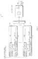
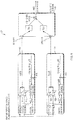
- Figures 5-8 schematically illustrate four additional configurations of the subject engine harmonic sound control system. They describe the case of multiple harmonics control between one speaker and one microphone, the case of one harmonic between multiple speakers and one microphone, the case of one harmonic between one speaker and multiple microphones, and the case of one harmonic between multiple speakers and multiple microphones, respectively. A combination of these four configurations would result in a multi-harmonic multiple input - multiple output system.
- the variable h TGT_X ( t ) is used to represent the target harmonics.
- Figure 5 illustrates system 50 that comprises elements 52 and 54 in the electronic domain that each accomplish the functions of the sine wave generator, the adaptive filter, the target harmonic generator and the modeled cabin transfer function of figure 1 , but for different harmonics (1 and N, respectively).
- the figure depicts just elements 52 and 54, for harmonics 1 and N, out of a greater number of harmonics.
- Acoustic domain elements 56 include the transducer, microphone and cabin transfer function S.
- Figure 6 illustrates a system 60 with two speakers and one microphone, and a single harmonic k.
- elements 62 and 64 accomplish the functions in the electronic domain
- element 66 accomplishes the functions in the acoustic domain and includes cabin transfer functions S 11 and S 21 .
- the target harmonic at the microphone location is created by playing signals out of both speakers. As the adaptive filters converge to minimize the error signals, the sum of the signals played out of the two speakers and the engine harmonic will add up to the target harmonic.
- the coefficients c 1k and c 2k are used to select by how much each of the speakers will contribute to construct the target harmonic.
- the coefficients are defined as function of RPM. This means that the system can select how much each speaker contributes at any given RPM.
- elements 82, 84, 86 and 88 each accomplish the functions in the electronic domain (at a single harmonic k, but for two different speakers), while element 90 accomplishes the functions in the acoustic domain and includes cabin transfer functions S 11 , S 12 for speaker 1, and S 21 , and S 22 for speaker 2.
- the coefficients c 1k , c 2k , d 1k , and d 2k are used to select by how much each of the speakers will contribute to construct the target harmonic.
- the coefficients are defined as a function of RPM. This means that the system can select how much each speaker contributes at any given RPM.
- Embodiments of the systems and methods described above comprise computer components and computer-implemented steps that will be apparent to those skilled in the art.
- the computer-implemented steps may be stored as computer-executable instructions on a computer-readable medium such as, for example, floppy disks, hard disks, optical disks, Flash ROMS, nonvolatile ROM, and RAM.
- the computer-executable instructions may be executed on a variety of processors such as, for example, microprocessors, digital signal processors, gate arrays, etc.
Landscapes
- Physics & Mathematics (AREA)
- Engineering & Computer Science (AREA)
- Acoustics & Sound (AREA)
- Multimedia (AREA)
- Health & Medical Sciences (AREA)
- Audiology, Speech & Language Pathology (AREA)
- General Health & Medical Sciences (AREA)
- Fittings On The Vehicle Exterior For Carrying Loads, And Devices For Holding Or Mounting Articles (AREA)
- Soundproofing, Sound Blocking, And Sound Damping (AREA)
Claims (15)
- Verfahren, umfassend:in einem Fahrzeugmotor-Oberwellenmodifizierungssystem (10) für eine Fahrgastzelle (12),Generieren (22) eines Ziel-Motoroberwellensignals ungleich Null, das repräsentativ für einen Ziel-Motoroberwellen-Geräuschpegel in der Fahrgastzelle ist, und das beide, Größen- und Phasenziele umfasst, wobei das Fahrzeugmotor-Oberwellenmodifizierungssystem ein Mikrofon (18) umfasst, das Motoroberwellengeräusche in der Fahrgastzelle erfasst, und einen Ausgabewandler (14) zum Erzeugen einer Annäherung des Ziel-Motoroberwellen-Geräuschpegels an einer Stelle des Mikrofons, undVerwenden des Ziel-Motoroberwellensignals in einem Betrieb des Motor-Oberwellenmodifizierungssystems, um den Pegel des Motoroberwellengeräusches in der Fahrgastzelle zu modifizieren, indem das Ziel-Motoroberwellensignal von einem Ausgabesignal des Mikrofons in der elektronischen Domäne subtrahiert wird (19), um ein Zielfehlersignal zu kreieren, und indem das Zielfehlersignal abgesteuert wird, um den von dem Ausgabewandler gelieferten Motoroberwellen-Geräuschpegel in der Fahrgastzelle näher an den Ziel-Motoroberwellen-Geräuschpegel heranzubringen.
- Verfahren nach Anspruch 1, wobei das Fahrzeugmotor-Oberwellenmodifizierungssystem ein Motoroberwellen-Annullierungssystem (EHC) umfasst, das die Motoroberwellen-Geräuschpegel in der Fahrgastzelle reduziert.
- Verfahren nach Anspruch 1, wobei das Fahrzeugmotor-Oberwellenmodifizierungssystem ein Motoroberwellen-Verstärkungssystem (EHE) umfasst, das die Motoroberwellen-Geräuschpegel in der Fahrgastzelle erhöht.
- Verfahren nach Anspruch 1, wobei das Fahrzeugmotor-Oberwellenmodifizierungssystem ein Motoroberwellen-Annullierungssystem (EHC) umfasst, das die Motoroberwellen-Geräuschpegel in der Fahrgastzelle reduziert, und ein Motoroberwellen-Verstärkungssystem (EHE), das die Motoroberwellen-Geräuschpegel in der Fahrgastzelle erhöht.
- Verfahren nach Anspruch 1, wobei die Größen- und Phasenziele in Übersichtstabellen mit Tabelleneingängen für die Größenziele und die Phasenziele gespeichert sind.
- Verfahren nach Anspruch 5, weiter umfassend eine Interpolation zwischen Übersichtstabelleneingängen zum Bestimmen von Größen- und Phasenzielen, die nicht in den Übersichtstabellen sind.
- Verfahren nach Anspruch 4, wobei das EHE System mit Motordrehzahl eingegeben wird und das Zieloberwellensignal durch das EHE System generiert wird.
- Verfahren nach Anspruch 4, wobei es mindestens teilweise von der Drehzahl des Motors abhängig ist, ob das Motoroberwellengeräusch reduziert wird oder erhöht wird.
- Verfahren nach Anspruch 8, wobei das EHC System die Motoroberwellen unter einer besonderen Drehzahl des Motors reduziert und das EHE System die Motoroberwellen über der besonderen Drehzahl des Motors erhöht.
- Verfahren nach Anspruch 4, wobei das EHE System Oberwellen generiert, die in Phase mit den Fahrgastzellen-Motoroberwellengeräuschen sind.
- Verfahren nach Anspruch 4, wobei das Zielmotoroberwellensignal auf dem Pegel der Motoroberwellengeräusche basiert, die in der Fahrgastzelle erfasst werden.
- Verfahren nach Anspruch 4, wobei mehrere Lautsprecher verwendet werden, um den Pegel des Motoroberwellengeräusches in der Fahrgastzelle zu modifizeren, und wobei das Motor-Oberwellenmodifizierungssystem angeordnet ist, um auszuwählen, wieviel jeder Lautsprecher zu dem modifizierten Motor-Oberwellengeräuschpegel beiträgt.
- Motorgeräuschmanagementsystem (10) für eine Fahrgastzelle (12), umfassend:eine Schaltung (22) zum Generieren eines Oberwellenziels ungleich Null repräsentativ für ein Zielmotorgeräusch basierend auf einer gemessenen Motordrehzahl und das beides, Größen- und Phasenziele umfasst;ein Mikrofon (18) zum Messen eines Geräusches in einer Fahrgastzelle;einen Ausgabewandler (14) zum Erzeugen einer Annäherung des Ziel-Motoroberwellen-Geräuschpegels an einer Stelle des Mikrofons; undeine Schaltung (19, 20, 24, 25, 26) zum Treiben des Ausgabewandlers zum Minimieren eines Unterschieds zwischen dem Oberwellenziel und der Annäherung des Ziel-Motoroberwellengeräusches, indem das Oberwellenziel von einem Ausgabesignal des Mikrofons in der elektronischen Domäne subtrahiert wird, um ein Zielfehlersignal zu kreieren, und indem das Zielfehlersignal abgesteuert wird.
- Motorgeräuschmanagementsystem (10) nach Anspruch 13, wobei die Schaltung zum Treiben des Ausgabewandlers einen adaptiven Filter (20) umfasst.
- Motorgeräuschmanagementsystem (10) nach Anspruch 13, wobei die Schaltung zum Erzeugen des Oberwellenziels eine oder mehrere Übersichtstabellen umfasst, die die gemessene Motorgeschwindigkeit auf Größen- und Phasenwerte für das Oberwellenziel abbildet.
Applications Claiming Priority (2)
| Application Number | Priority Date | Filing Date | Title |
|---|---|---|---|
| US14/667,164 US9812113B2 (en) | 2015-03-24 | 2015-03-24 | Vehicle engine harmonic sound control |
| PCT/US2016/023600 WO2016154211A1 (en) | 2015-03-24 | 2016-03-22 | Vehicle engine harmonic sound control |
Publications (2)
| Publication Number | Publication Date |
|---|---|
| EP3274987A1 EP3274987A1 (de) | 2018-01-31 |
| EP3274987B1 true EP3274987B1 (de) | 2020-01-08 |
Family
ID=55661619
Family Applications (1)
| Application Number | Title | Priority Date | Filing Date |
|---|---|---|---|
| EP16714687.7A Active EP3274987B1 (de) | 2015-03-24 | 2016-03-22 | Harmonische schallsteuerung für fahrzeugmotor |
Country Status (5)
| Country | Link |
|---|---|
| US (1) | US9812113B2 (de) |
| EP (1) | EP3274987B1 (de) |
| JP (2) | JP6594996B2 (de) |
| CN (1) | CN107408382B (de) |
| WO (1) | WO2016154211A1 (de) |
Families Citing this family (11)
| Publication number | Priority date | Publication date | Assignee | Title |
|---|---|---|---|---|
| JP6586982B2 (ja) * | 2017-10-06 | 2019-10-09 | マツダ株式会社 | 車両音響制御装置 |
| EP3553772A1 (de) | 2018-04-09 | 2019-10-16 | Harman International Industries, Incorporated | Verfahren und vorrichtung zum steuern von fahrzeuggeräuschen in einem fahrzeug |
| US11437015B2 (en) * | 2018-06-12 | 2022-09-06 | Harman International Industries, Incorporated | System and method for adaptive magnitude vehicle sound synthesis |
| KR102692478B1 (ko) * | 2018-12-13 | 2024-08-07 | 현대자동차주식회사 | 차량 사운드 인덱스 기반 인공지능 엔진음색 제어시스템 및 방법 |
| EP3970388B1 (de) * | 2019-05-16 | 2026-04-22 | Bose Corporation | Schallunterdrückung mittels mikrofonprojektion |
| KR102663217B1 (ko) * | 2019-10-17 | 2024-05-03 | 현대자동차주식회사 | 차량의 실내 음향 제어 방법 및 시스템 |
| JP7421725B2 (ja) * | 2020-01-21 | 2024-01-25 | マツダ株式会社 | 車両用音生成装置 |
| US11257477B2 (en) * | 2020-03-18 | 2022-02-22 | Harman International Industries, Incorporated | Motor noise masking |
| JP7090827B2 (ja) * | 2020-04-06 | 2022-06-24 | 三菱電機株式会社 | エンジン音制御装置、プログラム及びエンジン音制御方法 |
| US11417306B2 (en) * | 2020-12-31 | 2022-08-16 | Bose Corporation | Systems and methods for engine harmonic cancellation |
| RU2763309C1 (ru) * | 2021-03-22 | 2021-12-28 | Павел Романович Громов | Адаптивный способ активного гашения шума в салоне автомобиля и устройство для его реализации |
Family Cites Families (24)
| Publication number | Priority date | Publication date | Assignee | Title |
|---|---|---|---|---|
| JP2748625B2 (ja) * | 1989-12-29 | 1998-05-13 | 日産自動車株式会社 | 能動型騒音制御装置 |
| JP3203491B2 (ja) * | 1991-05-30 | 2001-08-27 | 株式会社ジェルテック | インシュレータ |
| JP2751685B2 (ja) * | 1991-09-18 | 1998-05-18 | 日産自動車株式会社 | 能動型騒音制御装置 |
| US5359662A (en) * | 1992-04-29 | 1994-10-25 | General Motors Corporation | Active noise control system |
| JP3843082B2 (ja) * | 2003-06-05 | 2006-11-08 | 本田技研工業株式会社 | 能動型振動騒音制御装置 |
| JP4314212B2 (ja) * | 2005-05-30 | 2009-08-12 | 本田技研工業株式会社 | 車両用能動型騒音・振動・効果音発生制御システム及び該システムが搭載された車両 |
| DE102005060064A1 (de) | 2005-12-15 | 2007-06-21 | Müller-BBM GmbH | Verfahren und System zur aktiven Geräuschbeeinflussung, Verwendung in einem Kraftfahrzeug |
| CN101231846B (zh) * | 2007-12-27 | 2011-02-02 | 中国农业大学 | 利用声波干涉方式的主动噪声控制系统及噪声控制方法 |
| EP2133866B1 (de) * | 2008-06-13 | 2016-02-17 | Harman Becker Automotive Systems GmbH | Adaptives Geräuschdämpfungssystem |
| US8718289B2 (en) * | 2009-01-12 | 2014-05-06 | Harman International Industries, Incorporated | System for active noise control with parallel adaptive filter configuration |
| CN101552939B (zh) * | 2009-05-13 | 2012-09-05 | 吉林大学 | 车内声品质自适应主动控制系统和方法 |
| JP4967000B2 (ja) * | 2009-06-30 | 2012-07-04 | 本田技研工業株式会社 | 効果音発生装置 |
| US8320581B2 (en) | 2010-03-03 | 2012-11-27 | Bose Corporation | Vehicle engine sound enhancement |
| US9179237B2 (en) * | 2011-12-16 | 2015-11-03 | Bose Corporation | Virtual audio system tuning |
| US8892046B2 (en) | 2012-03-29 | 2014-11-18 | Bose Corporation | Automobile communication system |
| JP5713958B2 (ja) * | 2012-05-22 | 2015-05-07 | 本田技研工業株式会社 | 能動型騒音制御装置 |
| EP2685448B1 (de) * | 2012-07-12 | 2018-09-05 | Harman Becker Automotive Systems GmbH | Motorenklangsynthese |
| US9031248B2 (en) | 2013-01-18 | 2015-05-12 | Bose Corporation | Vehicle engine sound extraction and reproduction |
| US9167067B2 (en) | 2013-02-14 | 2015-10-20 | Bose Corporation | Motor vehicle noise management |
| US9118987B2 (en) | 2013-03-12 | 2015-08-25 | Bose Corporation | Motor vehicle active noise reduction |
| JP5822862B2 (ja) * | 2013-03-21 | 2015-11-25 | 本田技研工業株式会社 | 車両用能動型振動騒音制御装置 |
| US9177542B2 (en) | 2013-03-29 | 2015-11-03 | Bose Corporation | Motor vehicle adaptive feed-forward noise reduction |
| US20150172807A1 (en) * | 2013-12-13 | 2015-06-18 | Gn Netcom A/S | Apparatus And A Method For Audio Signal Processing |
| CN103915091A (zh) * | 2014-03-26 | 2014-07-09 | 浙江大学 | 基于无次级通道建模的自适应算法的有源噪声控制方法 |
-
2015
- 2015-03-24 US US14/667,164 patent/US9812113B2/en active Active
-
2016
- 2016-03-22 CN CN201680017502.2A patent/CN107408382B/zh active Active
- 2016-03-22 WO PCT/US2016/023600 patent/WO2016154211A1/en not_active Ceased
- 2016-03-22 EP EP16714687.7A patent/EP3274987B1/de active Active
- 2016-03-22 JP JP2017549720A patent/JP6594996B2/ja active Active
-
2019
- 2019-08-01 JP JP2019142275A patent/JP2019206338A/ja active Pending
Non-Patent Citations (1)
| Title |
|---|
| None * |
Also Published As
| Publication number | Publication date |
|---|---|
| JP2019206338A (ja) | 2019-12-05 |
| JP2018516193A (ja) | 2018-06-21 |
| JP6594996B2 (ja) | 2019-10-23 |
| CN107408382A (zh) | 2017-11-28 |
| US9812113B2 (en) | 2017-11-07 |
| WO2016154211A1 (en) | 2016-09-29 |
| US20160284334A1 (en) | 2016-09-29 |
| EP3274987A1 (de) | 2018-01-31 |
| CN107408382B (zh) | 2021-02-05 |
Similar Documents
| Publication | Publication Date | Title |
|---|---|---|
| EP3274987B1 (de) | Harmonische schallsteuerung für fahrzeugmotor | |
| EP2939233B1 (de) | Aktive minderung von harmonischen störgeräuschen aus mehreren drehvorrichtungen | |
| JP4513810B2 (ja) | 能動騒音低減装置 | |
| US9344796B2 (en) | Active reduction of harmonic noise from multiple noise sources | |
| EP2973541B1 (de) | Aktive rauschunterdrückung bei einem kraftfahrzeug | |
| CN102187389B (zh) | 有源降噪自适应滤波器自适应率调节 | |
| US9177542B2 (en) | Motor vehicle adaptive feed-forward noise reduction | |
| CN105814627B (zh) | 有源噪声控制系统 | |
| US9478209B2 (en) | Tunable active noise control | |
| US5410606A (en) | Noise canceling method | |
| CN106716522B (zh) | 来自多个噪声源的谐波噪声的主动减小 | |
| EP3424043B1 (de) | Geräuschmanagement bei einem fahrzeugmotor | |
| JP2007272008A (ja) | 能動型騒音制御装置及び能動型振動制御装置 | |
| JP5238368B2 (ja) | 車両用能動型音響制御システム | |
| JP5503023B2 (ja) | 能動型振動騒音制御装置、能動型振動騒音制御方法及び能動型振動騒音制御プログラム | |
| JP2000172281A (ja) | 車室内音制御装置 | |
| JP2011043636A (ja) | 能動型消音システム |
Legal Events
| Date | Code | Title | Description |
|---|---|---|---|
| STAA | Information on the status of an ep patent application or granted ep patent |
Free format text: STATUS: THE INTERNATIONAL PUBLICATION HAS BEEN MADE |
|
| PUAI | Public reference made under article 153(3) epc to a published international application that has entered the european phase |
Free format text: ORIGINAL CODE: 0009012 |
|
| STAA | Information on the status of an ep patent application or granted ep patent |
Free format text: STATUS: REQUEST FOR EXAMINATION WAS MADE |
|
| 17P | Request for examination filed |
Effective date: 20170915 |
|
| AK | Designated contracting states |
Kind code of ref document: A1 Designated state(s): AL AT BE BG CH CY CZ DE DK EE ES FI FR GB GR HR HU IE IS IT LI LT LU LV MC MK MT NL NO PL PT RO RS SE SI SK SM TR |
|
| AX | Request for extension of the european patent |
Extension state: BA ME |
|
| DAV | Request for validation of the european patent (deleted) | ||
| DAX | Request for extension of the european patent (deleted) | ||
| STAA | Information on the status of an ep patent application or granted ep patent |
Free format text: STATUS: EXAMINATION IS IN PROGRESS |
|
| 17Q | First examination report despatched |
Effective date: 20180705 |
|
| GRAP | Despatch of communication of intention to grant a patent |
Free format text: ORIGINAL CODE: EPIDOSNIGR1 |
|
| STAA | Information on the status of an ep patent application or granted ep patent |
Free format text: STATUS: GRANT OF PATENT IS INTENDED |
|
| INTG | Intention to grant announced |
Effective date: 20191001 |
|
| GRAS | Grant fee paid |
Free format text: ORIGINAL CODE: EPIDOSNIGR3 |
|
| GRAA | (expected) grant |
Free format text: ORIGINAL CODE: 0009210 |
|
| STAA | Information on the status of an ep patent application or granted ep patent |
Free format text: STATUS: THE PATENT HAS BEEN GRANTED |
|
| AK | Designated contracting states |
Kind code of ref document: B1 Designated state(s): AL AT BE BG CH CY CZ DE DK EE ES FI FR GB GR HR HU IE IS IT LI LT LU LV MC MK MT NL NO PL PT RO RS SE SI SK SM TR |
|
| REG | Reference to a national code |
Ref country code: GB Ref legal event code: FG4D |
|
| REG | Reference to a national code |
Ref country code: CH Ref legal event code: EP |
|
| REG | Reference to a national code |
Ref country code: DE Ref legal event code: R096 Ref document number: 602016027772 Country of ref document: DE |
|
| REG | Reference to a national code |
Ref country code: IE Ref legal event code: FG4D |
|
| REG | Reference to a national code |
Ref country code: AT Ref legal event code: REF Ref document number: 1223672 Country of ref document: AT Kind code of ref document: T Effective date: 20200215 |
|
| REG | Reference to a national code |
Ref country code: NL Ref legal event code: MP Effective date: 20200108 |
|
| REG | Reference to a national code |
Ref country code: LT Ref legal event code: MG4D |
|
| PG25 | Lapsed in a contracting state [announced via postgrant information from national office to epo] |
Ref country code: FI Free format text: LAPSE BECAUSE OF FAILURE TO SUBMIT A TRANSLATION OF THE DESCRIPTION OR TO PAY THE FEE WITHIN THE PRESCRIBED TIME-LIMIT Effective date: 20200108 Ref country code: LT Free format text: LAPSE BECAUSE OF FAILURE TO SUBMIT A TRANSLATION OF THE DESCRIPTION OR TO PAY THE FEE WITHIN THE PRESCRIBED TIME-LIMIT Effective date: 20200108 Ref country code: RS Free format text: LAPSE BECAUSE OF FAILURE TO SUBMIT A TRANSLATION OF THE DESCRIPTION OR TO PAY THE FEE WITHIN THE PRESCRIBED TIME-LIMIT Effective date: 20200108 Ref country code: NL Free format text: LAPSE BECAUSE OF FAILURE TO SUBMIT A TRANSLATION OF THE DESCRIPTION OR TO PAY THE FEE WITHIN THE PRESCRIBED TIME-LIMIT Effective date: 20200108 Ref country code: PT Free format text: LAPSE BECAUSE OF FAILURE TO SUBMIT A TRANSLATION OF THE DESCRIPTION OR TO PAY THE FEE WITHIN THE PRESCRIBED TIME-LIMIT Effective date: 20200531 Ref country code: NO Free format text: LAPSE BECAUSE OF FAILURE TO SUBMIT A TRANSLATION OF THE DESCRIPTION OR TO PAY THE FEE WITHIN THE PRESCRIBED TIME-LIMIT Effective date: 20200408 |
|
| PG25 | Lapsed in a contracting state [announced via postgrant information from national office to epo] |
Ref country code: HR Free format text: LAPSE BECAUSE OF FAILURE TO SUBMIT A TRANSLATION OF THE DESCRIPTION OR TO PAY THE FEE WITHIN THE PRESCRIBED TIME-LIMIT Effective date: 20200108 Ref country code: BG Free format text: LAPSE BECAUSE OF FAILURE TO SUBMIT A TRANSLATION OF THE DESCRIPTION OR TO PAY THE FEE WITHIN THE PRESCRIBED TIME-LIMIT Effective date: 20200408 Ref country code: GR Free format text: LAPSE BECAUSE OF FAILURE TO SUBMIT A TRANSLATION OF THE DESCRIPTION OR TO PAY THE FEE WITHIN THE PRESCRIBED TIME-LIMIT Effective date: 20200409 Ref country code: SE Free format text: LAPSE BECAUSE OF FAILURE TO SUBMIT A TRANSLATION OF THE DESCRIPTION OR TO PAY THE FEE WITHIN THE PRESCRIBED TIME-LIMIT Effective date: 20200108 Ref country code: IS Free format text: LAPSE BECAUSE OF FAILURE TO SUBMIT A TRANSLATION OF THE DESCRIPTION OR TO PAY THE FEE WITHIN THE PRESCRIBED TIME-LIMIT Effective date: 20200508 Ref country code: LV Free format text: LAPSE BECAUSE OF FAILURE TO SUBMIT A TRANSLATION OF THE DESCRIPTION OR TO PAY THE FEE WITHIN THE PRESCRIBED TIME-LIMIT Effective date: 20200108 |
|
| REG | Reference to a national code |
Ref country code: DE Ref legal event code: R097 Ref document number: 602016027772 Country of ref document: DE |
|
| PG25 | Lapsed in a contracting state [announced via postgrant information from national office to epo] |
Ref country code: CZ Free format text: LAPSE BECAUSE OF FAILURE TO SUBMIT A TRANSLATION OF THE DESCRIPTION OR TO PAY THE FEE WITHIN THE PRESCRIBED TIME-LIMIT Effective date: 20200108 Ref country code: RO Free format text: LAPSE BECAUSE OF FAILURE TO SUBMIT A TRANSLATION OF THE DESCRIPTION OR TO PAY THE FEE WITHIN THE PRESCRIBED TIME-LIMIT Effective date: 20200108 Ref country code: SK Free format text: LAPSE BECAUSE OF FAILURE TO SUBMIT A TRANSLATION OF THE DESCRIPTION OR TO PAY THE FEE WITHIN THE PRESCRIBED TIME-LIMIT Effective date: 20200108 Ref country code: SM Free format text: LAPSE BECAUSE OF FAILURE TO SUBMIT A TRANSLATION OF THE DESCRIPTION OR TO PAY THE FEE WITHIN THE PRESCRIBED TIME-LIMIT Effective date: 20200108 Ref country code: DK Free format text: LAPSE BECAUSE OF FAILURE TO SUBMIT A TRANSLATION OF THE DESCRIPTION OR TO PAY THE FEE WITHIN THE PRESCRIBED TIME-LIMIT Effective date: 20200108 Ref country code: EE Free format text: LAPSE BECAUSE OF FAILURE TO SUBMIT A TRANSLATION OF THE DESCRIPTION OR TO PAY THE FEE WITHIN THE PRESCRIBED TIME-LIMIT Effective date: 20200108 Ref country code: ES Free format text: LAPSE BECAUSE OF FAILURE TO SUBMIT A TRANSLATION OF THE DESCRIPTION OR TO PAY THE FEE WITHIN THE PRESCRIBED TIME-LIMIT Effective date: 20200108 Ref country code: MC Free format text: LAPSE BECAUSE OF FAILURE TO SUBMIT A TRANSLATION OF THE DESCRIPTION OR TO PAY THE FEE WITHIN THE PRESCRIBED TIME-LIMIT Effective date: 20200108 |
|
| REG | Reference to a national code |
Ref country code: CH Ref legal event code: PL |
|
| PLBE | No opposition filed within time limit |
Free format text: ORIGINAL CODE: 0009261 |
|
| STAA | Information on the status of an ep patent application or granted ep patent |
Free format text: STATUS: NO OPPOSITION FILED WITHIN TIME LIMIT |
|
| REG | Reference to a national code |
Ref country code: AT Ref legal event code: MK05 Ref document number: 1223672 Country of ref document: AT Kind code of ref document: T Effective date: 20200108 |
|
| 26N | No opposition filed |
Effective date: 20201009 |
|
| REG | Reference to a national code |
Ref country code: BE Ref legal event code: MM Effective date: 20200331 |
|
| PG25 | Lapsed in a contracting state [announced via postgrant information from national office to epo] |
Ref country code: LU Free format text: LAPSE BECAUSE OF NON-PAYMENT OF DUE FEES Effective date: 20200322 |
|
| PG25 | Lapsed in a contracting state [announced via postgrant information from national office to epo] |
Ref country code: CH Free format text: LAPSE BECAUSE OF NON-PAYMENT OF DUE FEES Effective date: 20200331 Ref country code: LI Free format text: LAPSE BECAUSE OF NON-PAYMENT OF DUE FEES Effective date: 20200331 Ref country code: AT Free format text: LAPSE BECAUSE OF FAILURE TO SUBMIT A TRANSLATION OF THE DESCRIPTION OR TO PAY THE FEE WITHIN THE PRESCRIBED TIME-LIMIT Effective date: 20200108 Ref country code: IT Free format text: LAPSE BECAUSE OF FAILURE TO SUBMIT A TRANSLATION OF THE DESCRIPTION OR TO PAY THE FEE WITHIN THE PRESCRIBED TIME-LIMIT Effective date: 20200108 Ref country code: IE Free format text: LAPSE BECAUSE OF NON-PAYMENT OF DUE FEES Effective date: 20200322 |
|
| PG25 | Lapsed in a contracting state [announced via postgrant information from national office to epo] |
Ref country code: PL Free format text: LAPSE BECAUSE OF FAILURE TO SUBMIT A TRANSLATION OF THE DESCRIPTION OR TO PAY THE FEE WITHIN THE PRESCRIBED TIME-LIMIT Effective date: 20200108 Ref country code: SI Free format text: LAPSE BECAUSE OF FAILURE TO SUBMIT A TRANSLATION OF THE DESCRIPTION OR TO PAY THE FEE WITHIN THE PRESCRIBED TIME-LIMIT Effective date: 20200108 Ref country code: BE Free format text: LAPSE BECAUSE OF NON-PAYMENT OF DUE FEES Effective date: 20200331 |
|
| PG25 | Lapsed in a contracting state [announced via postgrant information from national office to epo] |
Ref country code: TR Free format text: LAPSE BECAUSE OF FAILURE TO SUBMIT A TRANSLATION OF THE DESCRIPTION OR TO PAY THE FEE WITHIN THE PRESCRIBED TIME-LIMIT Effective date: 20200108 Ref country code: MT Free format text: LAPSE BECAUSE OF FAILURE TO SUBMIT A TRANSLATION OF THE DESCRIPTION OR TO PAY THE FEE WITHIN THE PRESCRIBED TIME-LIMIT Effective date: 20200108 Ref country code: CY Free format text: LAPSE BECAUSE OF FAILURE TO SUBMIT A TRANSLATION OF THE DESCRIPTION OR TO PAY THE FEE WITHIN THE PRESCRIBED TIME-LIMIT Effective date: 20200108 |
|
| PG25 | Lapsed in a contracting state [announced via postgrant information from national office to epo] |
Ref country code: MK Free format text: LAPSE BECAUSE OF FAILURE TO SUBMIT A TRANSLATION OF THE DESCRIPTION OR TO PAY THE FEE WITHIN THE PRESCRIBED TIME-LIMIT Effective date: 20200108 Ref country code: AL Free format text: LAPSE BECAUSE OF FAILURE TO SUBMIT A TRANSLATION OF THE DESCRIPTION OR TO PAY THE FEE WITHIN THE PRESCRIBED TIME-LIMIT Effective date: 20200108 |
|
| PGFP | Annual fee paid to national office [announced via postgrant information from national office to epo] |
Ref country code: GB Payment date: 20260219 Year of fee payment: 11 |
|
| PGFP | Annual fee paid to national office [announced via postgrant information from national office to epo] |
Ref country code: DE Payment date: 20260219 Year of fee payment: 11 |
|
| PGFP | Annual fee paid to national office [announced via postgrant information from national office to epo] |
Ref country code: FR Payment date: 20260219 Year of fee payment: 11 |