EP3272954A1 - Ablaufanordnung - Google Patents
Ablaufanordnung Download PDFInfo
- Publication number
- EP3272954A1 EP3272954A1 EP16180668.2A EP16180668A EP3272954A1 EP 3272954 A1 EP3272954 A1 EP 3272954A1 EP 16180668 A EP16180668 A EP 16180668A EP 3272954 A1 EP3272954 A1 EP 3272954A1
- Authority
- EP
- European Patent Office
- Prior art keywords
- cover
- drainage
- drain
- latching
- opening
- Prior art date
- Legal status (The legal status is an assumption and is not a legal conclusion. Google has not performed a legal analysis and makes no representation as to the accuracy of the status listed.)
- Granted
Links
Images


Classifications
-
- E—FIXED CONSTRUCTIONS
- E03—WATER SUPPLY; SEWERAGE
- E03F—SEWERS; CESSPOOLS
- E03F5/00—Sewerage structures
- E03F5/04—Gullies inlets, road sinks, floor drains with or without odour seals or sediment traps
- E03F5/0407—Floor drains for indoor use
- E03F5/0408—Floor drains for indoor use specially adapted for showers
Definitions
- the present invention relates to a drain arrangement for a sanitary article, in particular for a drainage surface, especially for a shower surface, according to the preamble of claim 1.
- EP 1 229 174 Drainage arrangements for shower surfaces have become known from the prior art.
- the EP 1 229 174 such a drainage arrangement.
- a siphon is attached to a shower surface with several screws.
- the screws continue to serve as a storage element for a lid, which is connectable to the screws.
- Some users with an increased sense of cleanliness have in practice started to loosen the screws as well. This with the intention to clean other less accessible places.
- the release of the screws had, depending on the assembly, sometimes very negative consequences. For example, it may happen that the siphon falls from below the shower surface down and then can no longer be grasped by the user. Also, it may happen that the siphon due to pipes under tension removed from the drainage of the shower surface, whereby the siphon also can not be grasped by the user.
- the invention has for its object to provide a flow arrangement, which overcomes the disadvantages of the prior art.
- a mis-manipulation by the user should largely or be completely excluded.
- a drainage arrangement for a drainage surface comprises a drainage element having a drain opening extending around a central axis and having at least one attachment opening, which drainage element can be arranged below the drainage surface, at least one retaining element which can be arranged on the drainage surface on the upper side is, and at least one fastening element which is passed through the holding element and engages in the at least one mounting opening on the drainage element.
- the arrangement comprises a cover element, which is connectable to the holding element via a fixed connection, in particular via a substantially inseparable connection, wherein the cover element in the connected state covers the at least one fastening element.
- the cover By covering the fastener by the cover, there is the advantage that the user can no longer see the fastener and thus can not be tempted to remove the fasteners.
- the firm connection between the cover and the support member also ensures that the user can remove the cover.
- a "firm connection” or an “essentially inseparable connection” between the holding element and the cover element is understood to mean that the connection is mechanically fixed, in particular in the case of normal application of force in the course of a cleaning process, insoluble.
- the cover element preferably covers the at least one fastening element substantially completely.
- the expression “essentially completely covering” or “covering” means that the covering element covers the at least one fastening means in such a way that it can not be seen by a user in the installed state. The cover thus covers the parts of the fastener, which are not in engagement with the other elements.
- the cover is held exclusively on the holding element.
- the fixed connection between the holding element and cover is not adversely affected.
- the cover element In the installed position, the cover element preferably completely covers the parts of the fastening element which are visible from above. This means that the cover covers all the parts of the fastener, which are visible from above.
- above is meant a viewing direction in the installation position from above the drainage surface in the direction of the drainage element.
- connection between the cover element and retaining element is designed such that it is not destructive and / or solvable only with the aid of a tool.
- the holding element is a ring which completely revolves around the center axis and has a discharge opening. Through the drain opening water can flow from the drainage surface in the direction of drainage element.
- the holding element has at least one passage opening through which the fastening element can be passed. About this passage opening the fastener is guided in the direction of drainage element.
- the passage opening is preferably formed such that parts of the fastening element are present at the passage opening or adjacent thereto areas.
- the cover member is a ring segment which extends only partially around the central axis.
- a cover element is preferably provided per fastening element.
- the ring segment is firmly connected to the holding element in connection.
- the cover element is a around the central axis completely encircling ring with a drainage hole.
- the discharge opening is centrally located in the ring. Through this drain opening water can then flow to the drainage element.
- the annular cover member is fixed to the support member in connection.
- both the holding element and the cover are formed as rings, these two rings are preferably arranged concentrically to each other.
- the exposed in the installed state of the water overflowed surface of the cover is at least partially rounded and / or partially conical.
- the rounding or the conicity are such that a flow-optimized inlet of the water is made possible.
- the cover is held on at least one latching connection on the holding element.
- a latching connection With a latching connection, a very simple fixed connection between the cover element and the holding element can be provided.
- the latching connection comprises a latching tab and a locking recess corresponding to the latching tab.
- the locking tab is integrally formed on the cover and the retaining element has the latching recess.
- the locking tab is integrally formed on the holding element and the cover member has the latching recess.
- At least one locking tab is present between two adjacent fastening elements.
- the locking tab or the recess is arranged on the cover on the holding element oriented bottom and in such a way that the locking tab or the recess is not visible from above.
- the corresponding catch recess or latching tab on the holding element is preferably arranged on the upper side of the holding element or accessible from above.
- connection such as a non-positive and / or positive and / or cohesive connection between the holding element and the cover are under the proviso of the fixed connection also possible.
- the cover member has on its underside at least one recess into which can protrude parts of the fastener, wherein between the fastener and cover preferably no mechanical connection is made.
- the fastening elements do not enter into a connection with the cover element in this preferred embodiment, but merely protrude into the recess.
- the attachment opening in the drainage element is a threaded opening and the attachment element is a screw, wherein in particular the screw head of the screw can be covered by the cover element.
- the screw head is visible in the absence of the cover from above.
- the holding element on the underside a stop surface, with which the holding element bears against the drainage surface.
- the holding element on the upper side on a drainage surface Preferably, both the abutment surface and the discharge surface are oriented at an angle inclined to the central axis.
- the holding element between the central axis and the discharge surface provides a receiving area in which the cover is inserted.
- the exposed surface of the covering element overflowed by water adjoins flush with the discharge surface of the holding element. This can ensure a good drainage performance. In addition, the cleaning is very easy.
- the drainage arrangement further comprises a lid having a lid surface and latching elements, wherein the lid surface in the installation position spaced from the holding element and the cover element and wherein the latching elements are preferably received a latching connection with the cover.
- the locking connection between the lid and the cover has the advantage that the lid can be mounted very easily.
- the latching elements of the lid protrude into the drainage opening of the cover element and there are tethered to the inner wall of the drainage opening. This has the advantage that no parts of the lid extend into the drain element, which would be detrimental to the drainage capacity.
- the at least one fastening element and the retaining element as well as the cover element in the installed position are arranged substantially below the upper side of the drainage surface.
- the arrangement is such that the holding element and the cover are overflowed by the water to be discharged.
- the arrangement further comprises a drainage surface, which has a drain opening, wherein the drainage element is arranged on the underside of the drainage surface, and wherein the holding element is arranged on the upper side of the drainage surface and partly in the region of the drainage opening.
- a drainage surface is understood as meaning all water-carrying elements, such as a shower surface, a flat shower surface, a shower tray, a wash basin or the like.
- the drainage element preferably comprises a siphon insert, which can be removed from above for cleaning out of the drainage element.
- the drainage element preferably also comprises a seal which completely surrounds the drainage opening and which is clamped in the installation position against the underside of the drainage surface.
- a method for assembling an arrangement described above is characterized in that after the assembly of drainage element and retaining ring with the fastening elements, the cover element is firmly connected to the retaining ring.
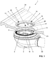
- a drainage arrangement 1 for a drainage area 2 is shown.
- a drainage surface is understood to be a substantially flat drainage surface or a shower tray.
- the drainage arrangement 1 according to the embodiment shown in the figures comprises a drainage element 3, at least one retaining element 6, at least one fastening element 7 and a cover element 8. Via the drainage arrangement 1, showering water can be removed from the drainage surface 2, for which the drainage arrangement 1 at the Drainage surface 2 is attached.
- the drainage element 3 has a drainage opening 4 extending around a central axis M and at least one fastening opening 5.
- the drainage element 3 can be arranged on the underside of the drainage surface 2.
- the drain element 3 is a siphon.
- the drainage element 3 also has a pipe socket 32, which can be connected to a sewage network.
- the at least one retaining element 6 can be arranged on the upper side of the drainage surface 2.
- the at least one fastening element 7 is passed through the holding element 6 and is mounted on the holding element 6. Next engages the fastener 7 in the at least one mounting opening 5 on the drain element 3 a. Due to the mounting of the fastening element 7 on the holding element 6, which can be arranged on the upper side to the drainage surface, the drainage element 3 can be attracted to the underside 23 of the drainage surface 2.
- three fastening elements 7 are arranged, which engage in three fastening openings 5.
- the three fastening elements 7 are arranged at regular intervals from one another.
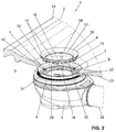
- the cover 8 is in the FIG. 2 spaced from the holding element 6 shown.
- the cover 8 In the FIGS. 3 to 5 is the cover 8 in the installed position.
- the cover element 8 In the installed position, the cover element 8 is connected to the holding element 6 via a fixed connection, in particular via a substantially inseparable connection, in connection. That is, the cover 8 is connectable to the support member 6 via a fixed connection.
- the connected state covers the cover 8, the at least one fastener 7 from.
- FIG. 2 In the FIG. 2 is the at least one fastening element 7 from above, so from the top 24 of the drainage surface 2 ago, visible. This means that a user can easily recognize the at least one fastening element 7.
- FIG. 3 In the FIG. 3 is the cover 8 in the mounted position. Here it is shown that the fastener 7 can no longer be detected by a user, because this is just covered by the cover 8 accordingly. Due to the fixed connection between the holding element 6 and cover 8, the cover 8 can not be removed without much effort, which prevents the user can continue to see the at least one fastener 7. Just the latter seduces him, as described above, to solve the same.
- the cover element 8 covers the fastening elements 7 in the installed position substantially in such a way that the visible from above parts of the fastener 7 are completely covered. This is in the FIG. 3 shown, from which it can be seen that the at least one fastener 7 can not be recognized due to the cover by the cover 6.
- connection between cover element 8 and retaining element 6 is designed such that it is fixed. This means that this connection can not be detached non-destructively. In other variants, this may mean that this connection can be solved only with the aid of a tool. Here, too, preferably, the connection is such that the cover 8 is destroyed.
- the holding element 6 is, as in the FIGS. 1 to 3 shown, around the central axis M completely circumferential ring.
- the ring in this case has a central outlet opening 9, through which water can be supplied from the upper side 24 of the drainage surface 2 to the drainage opening 4 of the drainage element 3.
- the holding element 6 has at least one passage opening 10, through which the fastening element 7 can be passed.
- the at least one passage opening 10 is arranged on a web region 26 which projects into the discharge opening 9. These passage openings 10 or the web areas 26 in this case provide a mounting for the fastening element 7, which is passed through the passage opening 10 ready.
- the fastening element 7 rests with a head portion 28 on the upper side on the web area, whereby a fixing action of the fastening element between the holding element 6 and the Drain element 3 can be provided.
- the cover member 8 as in the Figures 2 and 3 shown, also a completely circumferential ring with a drain opening 11. Through the drain opening 11, water from the top 24 of the drain surface 2 of the drain opening 4 of the drain element 3 can be supplied.
- the annular cover member 8 and the annular support member 6 are arranged concentrically with each other.
- the cover 8 may also be a ring segment. This is not shown in the figures.
- the exposed surface 27 of the cover element 8, which is overflowed by the water, is configured in a conical and sectionally rounded manner in sections in the embodiment shown.
- the rounded portion bears the reference numeral 29 and the conical portion the reference numeral 30. From the outside, the water flows first through the conical portion 30 and then via the rounded portion 29, which then opens into the drain opening 11.
- the cover 8 is held in the embodiment shown at least one locking connection 12 on the holding element.
- the latching connection establishes the solid connection.
- the latching connection 12 has, in the variant shown, a latching tab 13 and a latching recess 14 corresponding to the latching tab.
- the latching tab 13 is arranged on the cover element 8
- the latching recess 14 is arranged on the holding element 6 in the embodiment shown.
- the said locking connection 12 is provided.
- the locking tab 13 and the recess 14 are arranged such that they are not visible in the installed position from above substantially.
- FIG. 2 can be further recognized as the locking tab 13 in the recess 14 engages the retaining element.
- the cover 8 has on its underside 15 at least one recess 16, in which parts of the fastener 7 can protrude.
- the recess 16 and the fastening elements 7 are formed in such a way to each other that between the fastening element 7 and the cover 8 no mechanical connection is made. That is, the recess 16 essentially creates a cavity in which the fastening element 7 can protrude with play.
- the absence of a mechanical connection between the fastening element 7 and the cover element 8 has the advantage that said mechanical fixed connection between the cover element 8 and the retaining element 6 is not further influenced.
- the attachment opening in the drain element 3 is preferably a threaded opening.
- the fastening element 7 is preferably a screw, wherein in particular the screw head 28 of the screw can be covered by the cover. The screw head 28 abuts the upper side of the web region 26 on the holding element 6.
- the holding element 6 has a stop surface 17 on the underside, with which the holding element 6 bears against the drainage surface 2. In the embodiment shown, the holding element 6 abuts in the region of the drain opening 22 of the shower element 2.
- the holding element 6 has on the upper side a discharge surface 18, which has a certain conicity in the embodiment shown.
- the outflow surface 18 preferably adjoins directly the upper side 24 of the drainage surface 2 and then merges into the overflowed surface 27 of the cover element 8.
- FIG. 5 is symbolized by the arrow P the watercourse.
- the said surfaces 24, 18 and 27 are in such a way that the water is opposed as little resistance as possible. In particular, the surfaces are flush with each other.
- the support member 6, the cover 8 and the fasteners 7 are substantially below a plane defined by the top 24 plane.
- the plane bears the reference E in the FIG. 5 .
- the advantage of arranging these elements below the level is that one compact or flat design can be achieved.
- the fasteners 7 are not in the cross section of the inlet, which is the drainage performance of the drain assembly 1 beneficial.
- the holding element 6 in the embodiment shown has a receiving region 25.
- the cover 8 can be inserted.
- the drain arrangement comprises, as in the Figures 3 and 5
- the cover surface 20 lies in the installed position at a distance from the retaining element 6 and the cover element 8.
- the latching elements 21 enter into a latching connection at 8.
- the drain member 3 comprises a gasket 31 which extends completely around the drain hole 4.
- the seal 31 is in the installed position, as in the FIG. 5 shown, used by the fastening center against the bottom 23 of the drainage surface 2.
- the seal 31 provides a seal with respect to a water outlet between drain element 3 and drain surface 2.
- the seal 31 is arranged in a perimeter, which is outside the arrangement of the fastening elements 7.
Landscapes
- Health & Medical Sciences (AREA)
- Life Sciences & Earth Sciences (AREA)
- Engineering & Computer Science (AREA)
- Hydrology & Water Resources (AREA)
- Public Health (AREA)
- Water Supply & Treatment (AREA)
- Sink And Installation For Waste Water (AREA)
Abstract
Description
- Die vorliegende Erfindung betrifft eine Ablaufanordnung für einen Sanitärartikel, insbesondere für eine Ablauffläche, besonders für eine Duschfläche, nach dem Oberbegriff von Anspruch 1.
- Aus dem Stand der Technik sind Ablaufanordnungen für Duschflächen bekannt geworden. Beispielsweise offenbart die
EP 1 229 174 eine derartige Ablaufanordnung. Gemäss der technischen Lehre derEP 1 229 174 wird ein Siphonelement mit mehreren Schrauben an einer Duschfläche befestigt. Die Schrauben dienen weiter als Lagerungselement für einen Deckel, welcher mit den Schrauben verbindbar ist. Bei der periodischen Reinigung des Siphon ist der Deckel zu entfernen, wobei dann die Schrauben für den Benutzer sichtbar werden. Einige Benutzer mit gesteigertem Sinn für Sauberkeit sind in der Praxis dazu übergegangen, die Schrauben ebenfalls zu lösen. Dies mit der Intention weitere weniger gut zugängliche Orte zu reinigen. Das Lösen der Schrauben hatte, je nach Montage, teilweise sehr negative Konsequenzen. Beispielsweise kann es vorkommen, dass der Siphon von unterhalb der Duschfläche nach unten fällt und dann nicht mehr vom Benutzer ergriffen werden kann. Auch kann vorkommen, dass sich der Siphon aufgrund von unter Spannung verlegten Rohren von der Abflussöffnung der Duschfläche entfernt, wodurch der Siphon ebenfalls nicht mehr vom Benutzer ergriffen werden kann. - Ausgehend von diesem Stand der Technik liegt der Erfindung eine Aufgabe zugrunde, eine Ablaufanordnung anzugeben, welche die Nachteile des Standes der Technik überwindet. Insbesondere soll eine Fehlmanipulation von Seiten der Benutzer weitgehend bzw. vollständig ausgeschlossen werden.
- Diese Aufgabe löst der Gegenstand vom Anspruch 1. Demgemäss umfasst eine Ablaufanordnung für eine Ablauffläche ein Ablaufelement mit einer sich um eine Mittelachse herum erstreckenden Ablauföffnung und mit mindestens einer Befestigungsöffnung, welches Ablaufelement unterseitig zur Ablauffläche anordbar ist, mindestens ein Halteelement, das oberseitig zur Ablauffläche anordbar ist, und mindestens ein Befestigungselement, welches durch das Halteelement hindurchgeführt wird und in die mindestens eine Befestigungsöffnung am Ablaufelement eingreift. Weiter umfasst die Anordnung ein Abdeckelement, das mit dem Halteelement über eine feste Verbindung, insbesondere über eine im Wesentlichen untrennbare Verbindung, verbindbar ist, wobei das Abdeckelement in verbundenem Zustand das mindestens eine Befestigungselement abdeckt.
- Durch die Abdeckung des Befestigungselementes durch das Abdeckelement ergeht der Vorteil, dass der Benutzer das Befestigungselement nicht mehr sehen und somit nicht in Versuchung kommen kann, die Befestigungselemente zu entfernen. Durch die feste Verbindung zwischen dem Abdeckelement und dem Halteelement wird zudem sichergestellt, dass der Benutzer das Abdeckelement entfernen kann.
- Unter einer "festen Verbindung" bzw. unter einer "im Wesentlichen untrennbaren Verbindung" zwischen dem Halteelement und dem Abdeckelement wird verstanden, dass die Verbindung mechanisch fest, insbesondere bei normaler Kraftanwendung im Zuge eines Reinigungsvorgangs unlösbar, ist.
- Vorzugsweise deckt das Abdeckelement das mindestens eine Befestigungselement im Wesentlichen vollständig ab. Unter der Ausdrucksweise "im Wesentlichen vollständig abdecken" bzw. "abdecken" wird verstanden, dass das Abdeckelement das mindestens eine Befestigungsmittel derart abdeckt, dass dieses im eingebauten Zustand von einem Benutzer nicht gesehen werden kann. Das Abdeckelement deckt also die Teile des Befestigungselementes ab, welche nicht im Eingriff mit den anderen Elementen sind.
- Vorzugsweise wird das Abdeckelement ausschliesslich am Halteelement gehalten. Das heisst, das Abdeckelement geht keine Verbindung mit dem Befestigungselement ein. Hierdurch wird die feste Verbindung zwischen Halteelement und Abdeckelement nicht negativ beeinflusst.
- Vorzugsweise deckt das Abdeckelement in Einbaulage die von oben her sichtbaren Teile des Befestigungselements vollständig ab. Das heisst, dass das Abdeckelement alle die Teile des Befestigungselementes abdeckt, welche von oben her sichtbar sind.
- Unter von "oben her" wird eine Betrachtungsrichtung in Einbaulage von oberhalb der Ablauffläche in Richtung Ablaufelement verstanden.
- Vorzugsweise ist die Verbindung zwischen Abdeckelement und Halteelement derart ausgebildet, dass diese nicht zerstörungsfrei und/oder ausschliesslich unter Zuhilfenahme eines Werkzeuges lösbar ist.
- Vorzugsweise ist das Haltelement ein um die Mittelachse vollständig umlaufender Ring mit einer Abflussöffnung. Durch die Abflussöffnung kann Wasser von der Ablauffläche in Richtung Ablaufelement fliessen.
- Besonders bevorzugt weist das Halteelement mindestens eine Durchgangsöffnung auf, durch welche das Befestigungselement hindurchführbar ist. Über diese Durchgangsöffnung wird das Befestigungselement in Richtung Ablaufelement geführt.
- Die Durchgangsöffnung ist vorzugsweise derart ausgebildet, dass Teile des Befestigungselementes an der Durchgangsöffnung oder dazu benachbarten Bereichen anstehen.
- In einer ersten bevorzugten Ausführungsform ist das Abdeckelement ein Ringsegment, welches sich nur teilweise um die Mittelachse herum erstreckt. Gemäss dieser Ausführungsform ist vorzugsweise pro Befestigungselement je ein Abdeckelement vorgesehen. Das Ringsegment steht fest mit dem Halteelement in Verbindung.
- In einer zweiten bevorzugten Ausführung ist das Abdeckelement ein um die Mittelachse vollständig umlaufender Ring mit einer Abflussöffnung ist. Die Abflussöffnung liegt dabei zentral im Ring. Durch diese Abflussöffnung kann dann Wasser zum Ablaufelement fliessen. Das ringförmige Abdeckelement steht fest mit dem Halteelement in Verbindung.
- Sofern sowohl das Halteelement als auch das Abdeckelement als Ringe ausgebildet sind, sind diese beiden Ringe vorzugweise konzentrisch zueinander angeordnet.
- Vorzugsweise ist die im eingebauten Zustand freiliegende vom Wasser überströmte Oberfläche des Abdeckelementes mindestens abschnittsweise gerundet und/oder abschnittsweise konisch ausgebildet ist.
- Die Rundung bzw. die Konizität sind dabei derart, dass ein strömungsoptimierter Einlauf des Wassers ermöglicht wird.
- Vorzugsweise wird das Abdeckelement über mindestens eine Rastverbindung am Halteelement gehalten. Mit einer Rastverbindung kann eine sehr einfache feste Verbindung zwischen dem Abdeckelement und dem Halteelement bereitgestellt werden.
- Besonders bevorzugt umfasst die Rastverbindung eine Rastlasche und eine mit der Rastlasche korrespondierende Rastausnehmung. Nach einer ersten Variante ist am Abdeckelement die Rastlasche angeformt und das Halteelement weist die Rastausnehmung auf. Nach einer zweiten Variante ist am Halteelement die Rastlasche angeformt und das Abdeckelement weist die Rastausnehmung auf.
- Besonders bevorzugt ist zwischen zwei benachbarten Befestigungselementen mindestens eine Rastlasche vorhanden.
- Vorzugsweise ist die Rastlasche oder die Rastausnehmung am Abdeckelement an der zum Halteelement orientierten Unterseite angeordnet und zwar derart, dass die Rastlasche oder die Rastausnehmung von oben her nicht sichtbar ist. Die korrespondiere Rastausnehmung bzw. Rastlasche am Halteelement ist vorzugsweise an der Oberseite des Halteelementes angeordnet bzw. von oben her zugänglich.
- Andere Arten der Verbindung, wie beispielsweise eine kraftschlüssige und/oder formschlüssige und/oder stoffschlüssige Verbindung zwischen dem Halteelement und dem Abdeckelement sind unter der Massgabe der festen Verbindung ebenfalls möglich.
- Vorzugsweise weist das Abdeckelement auf seiner Unterseite mindestens eine Aussparung auf, in welche Teile des Befestigungselementes einragen können, wobei zwischen Befestigungselement und Abdeckelement vorzugsweise keine mechanische Verbindung hergestellt wird. Da heisst, dass die Befestigungselemente in dieser bevorzugten Ausführungsform nicht eine Verbindung mit dem Abdeckelement eingehen, sondern lediglich in die Aussparung einragen. Besonders bevorzugt ist zwischen Aussparung und den in die Aussparung einragenden Teile Spiel vorhanden, so dass ein Kontakt zwischen Aussparung und Befestigungselement verhindert wird.
- Das nicht-vorhandensein einer mechanischen Verbindung zwischen dem Abdeckelement und dem Befestigungselement hat den Vorteil, dass die feste Verbindung zwischen Abdeckelement und Halteelement nicht negativ beeinflusst wird.
- Vorzugsweise ist die Befestigungsöffnung im Ablaufelement eine Gewindeöffnung und das Befestigungselement ist eine Schraube, wobei insbesondere der Schraubenkopf der Schraube durch das Abdeckelement abdeckbar ist. Der Schraubenkopf ist bei nichtvorhandensein des Abdeckelementes von oben her sichtbar.
- Vorzugsweise weist das Halteelement unterseitig eine Anschlagsfläche auf, mit welcher das Halteelement an der Ablauffläche anliegt. Weiter weist das Halteelement oberseitig eine Abflussfläche auf. Vorzugsweise sind sowohl die Anschlagsfläche als auch Abflussfläche winklig geneigt zur Mittelachse orientiert.
- Besonders bevorzugt stellt das Haltelement zwischen der Mittelachse und der Abflussfläche einen Aufnahmebereich bereit, in welchen das Abdeckelement einlegbar ist. Besonders bevorzugt schliesst sich die freiliegende vom Wasser überströmte Oberfläche des Abdeckelementes bündig an die Abflussfläche des Halteelementes an. Hierdurch kann für eine gute Abflussleistung gesorgt werden. Darüber hinaus ist die Reinigung sehr einfach.
- Vorzugsweise umfasst die Ablaufanordnung weiterhin einen Deckel mit einer Deckelfläche und Rastelementen, wobei die Deckelfläche in Einbaulage beabstandet zum Halteelement und zum Abdeckelement liegt und wobei die Rastelemente vorzugsweise eine Rastverbindung mit dem Abdeckelement eingehen.
- Die Rastverbindung zwischen dem Deckel und dem Abdeckelement hat den Vorteil, dass der Deckel sehr einfach montiert werden kann.
- Vorzugsweise rage die Rastelemente des Deckels in die Abflussöffnung des Abdeckelementes ein und verharken sich dort an der Innenwand der Abflussöffnung. Das hat den Vorteil, dass sich keine Teile des Deckels in das Ablaufelement hinein erstrecken, was bezüglich der Abflussleistung nachteilig wäre.
- Vorzugsweise sind das mindestens eine Befestigungselement sowie das Halteelement als auch das Abdeckelement in Einbaulage gesehen im Wesentlichen unterhalb der Oberseite der Ablauffläche angeordnet. Die Anordnung ist dabei derart, dass das Halteelement und das Abdeckelement vom abzuführenden Wasser überströmt werden. Durch die Abdeckung des mindestens einen Befestigungselementes durch das Abdeckelement ergeht zudem der Vorteil, dass das abzuführende Wasser nicht mit dem Befestigungselement in Kontakt kommt.
- Vorzugsweise umfasst die Anordnung weiterhin eine Ablauffläche, welche eine Abflussöffnung aufweist, wobei das Ablaufelement an der Unterseite der Ablauffläche angeordnet ist, und wobei das Halteelement an der Oberseite der Ablauffläche und teilweise im Bereich der Abflussöffnung angeordnet ist.
- Unter einer Ablauffläche werden sämtliche wasserführenden Elemente, wie eine Duschfläche, eine ebene Duschfläche, eine Duschwanne, ein Waschtisch oder ähnliches verstanden.
- Das Ablaufelement umfasst vorzugsweise einen Siphoneinsatz, welcher von oben her zur Reinigung aus dem Ablaufelement entfernt werden kann.
- Vorzugsweise umfasst das Ablaufelement zudem eine die Ablauföffnung vollständig umgebende Dichtung auf, welche in Einbaulage gegen die Unterseite der Ablauffläche geklemmt wird.
- Ein Verfahren zur Montage einer oben beschriebenen Anordnung ist dadurch gekennzeichnet, dass nach der Montage von Ablaufelement und Haltering mit den Befestigungselementen, das Abdeckelement mit dem Haltering fest verbunden wird.
- Weitere Ausführungsformen sind in den abhängigen Ansprüchen angegeben.
- Bevorzugte Ausführungsformen der Erfindung werden im Folgenden anhand der Zeichnungen beschrieben, die lediglich zur Erläuterung dienen und nicht einschränkend auszulegen sind. In den Zeichnungen zeigen:
- Fig. 1
- eine perspektivische Ansicht einer Ablaufanordnung nach einer Ausführungsform der vorliegenden Erfindung;
- Fig. 2
- eine weitere perspektivische Ansicht der Ablaufanordnung nach
Figur 1 ; - Fig. 3
- eine weitere perspektivische Ansicht der Ablaufanordnung nach
Figur 1 ; - Fig. 4
- eine Schnittdarstellung der Ablaufanordnung nach
Figur 1 in Einbaulage; und - Fig. 5
- eine Detailansicht nach
Figur 4 . - In den Figuren wird eine Ablaufanordnung 1 für eine Ablauffläche 2 gezeigt. Unter einer Ablauffläche wird eine im Wesentlichen ebene Ablauffläche oder eine Duschwanne verstanden. Die Ablaufanordnung 1 nach der in den Figuren gezeigten Ausführungsform umfasst ein Ablaufelement 3, mindestens ein Halteelement 6, mindestens ein Befestigungselement 7 sowie ein Abdeckelement 8. Über die Ablaufanordnung 1 kann Duschwasser von der Ablauffläche 2 entfernt werden, wofür die Ablaufanordnung 1 an der Ablauffläche 2 befestigt ist.
- Das Ablaufelement 3 weist in der gezeigten Ausführungsform eine sich um eine Mittelachse M herumerstreckende Ablauföffnung 4 und mindestens eine Befestigungsöffnung 5 auf. Das Ablaufelement 3 ist unterseitig zur Ablauffläche 2 anordbar. Typischerweise ist das Ablaufelement 3 ein Siphon. In der gezeigten Ausführungsform weist das Ablaufelement 3 zudem ein Rohrstutzen 32 auf, welcher an ein Abwassernetz anschliessbar ist.
- Das mindestens eine Halteelement 6 ist oberseitig zur Ablauffläche 2 anordbar. Das mindestens eine Befestigungselement 7 ist durch das Halteelement 6 hindurchgeführt und wird am Halteelement 6 gelagert. Weiter greift das Befestigungselement 7 in die mindestens eine Befestigungsöffnung 5 am Ablaufelement 3 ein. Durch die Lagerung des Befestigungselementes 7 am Halteelement 6, welches oberseitig zur Ablauffläche anordbar ist, kann das Ablaufelement 3 zur Unterseite 23 der Ablauffläche 2 angezogen werden.
- In der gezeigten Ausführungsform sind drei Befestigungselemente 7 angeordnet, welche in drei Befestigungsöffnungen 5 eingreifen. Die drei Befestigungselemente 7 sind dabei in regelmässigen Abständen zueinander angeordnet.
- Weiter umfasst die Ablaufanordnung 1, wie in den
Figuren 2 bis 5 gezeigt, ein Abdeckelement 8. Das Abdeckelement 8 wird in derFigur 2 beabstandet zum Halteelement 6 dargestellt. In denFiguren 3 bis 5 befindet sich das Abdeckelement 8 in Einbaulage. In Einbaulage steht das Abdeckelement 8 mit dem Halteelement 6 über eine feste Verbindung, insbesondere über eine im Wesentlichen untrennbare Verbindung, in Verbindung. Das heisst, das Abdeckelement 8 ist mit dem Halteelement 6 über eine feste Verbindung verbindbar. Im verbundenen Zustand deckt das Abdeckelement 8 das mindestens eine Befestigungselement 7 ab. - In der
Figur 2 ist das mindestens eine Befestigungselement 7 von oben her, also von der Oberseite 24 der Ablauffläche 2 her, sichtbar. Das heisst ein Benutzer kann das mindestens eine Befestigungselement 7 ohne weiteres erkennen. In derFigur 3 befindet sich das Abdeckelement 8 in der montierten Lage. Hier wird gezeigt, dass das Befestigungselement 7 nicht mehr durch einen Benutzer erkannt werden kann, weil dieses eben durch das Abdeckelement 8 entsprechend abgedeckt ist. Aufgrund der festen Verbindung zwischen Haltelement 6 und Abdeckelement 8 kann das Abdeckelement 8 auch nicht mehr ohne grösseren Aufwand entfernt werden, was verhindert, dass der Benutzer das mindestens eine Befestigungselement 7 weiterhin sehen kann. Gerade Letzteres verführt ihn, wie oben beschrieben, zum Lösen desselben. - Das Abdeckelement 8 deckt die Befestigungselemente 7 in Einbaulage im Wesentlichen derart ab, dass die von oben her sichtbaren Teile des Befestigungselementes 7 vollständig abgedeckt werden. Dies wird in der
Figur 3 gezeigt, von welcher entnommen werden kann, dass das mindestens eine Befestigungselement 7 aufgrund der Abdeckung durch das Abdeckelement 6 nicht mehr erkannt werden kann. - Die Verbindung zwischen Abdeckelement 8 und Halteelement 6 ist derart ausgebildet, dass diese fest ist. Das heisst, diese Verbindung ist nicht zerstörungsfrei lösbar. In weiteren Varianten kann dies heissen, dass diese Verbindung ausschliesslich unter Zuhilfenahme eines Werkzeuges lösbar ist. Wobei auch hier vorzugsweise die Verbindung derart ist, dass diese das Abdeckelement 8 zerstört wird.
- Das Halteelement 6 ist, wie in den
Figuren 1 bis 3 gezeigt, ein um die Mittelachse M vollständig umlaufender Ring. Der Ring weist dabei eine zentrale Abflussöffnung 9 auf, durch welche Wasser von der Oberseite 24 der Ablauffläche 2 zur Ablauföffnung 4 des Ablaufelementes 3 zugeführt werden kann. - Weiter weist das Halteelement 6 mindestens eine Durchgangsöffnung 10 auf, durch welche das Befestigungselement 7 hindurchführbar ist. Hier sind drei Durchgangsöffnungen 10 für die drei Befestigungselemente 7 vorhanden. In der gezeigten Ausführungsform ist die mindestens eine Durchgangsöffnung 10 an einem Stegbereich 26 angeordnet, welcher in die Abflussöffnung 9 einragt. Diese Durchgangsöffnungen 10 beziehungsweise die Stegbereiche 26 stellen dabei eine Lagerung für das Befestigungselement 7, das durch die Durchgangsöffnung 10 hindurchgeführt wird, bereit. Das Befestigungselement 7 liegt mit einen Kopfabschnitt 28 oberseitig am Stegbereich an, wodurch beim Fixieren des Befestigungselements eine Klemmwirkung zwischen dem Halteelement 6 und dem Ablaufelement 3 bereitgestellt werden kann.
- In der gezeigten Ausführungsform ist das Abdeckelement 8, wie in den
Figuren 2 und3 gezeigt, ebenfalls ein vollständig umlaufender Ring mit einer Abflussöffnung 11. Durch die Abflussöffnung 11 kann Wasser von der Oberseite 24 der Ablauffläche 2 der Ablauföffnung 4 des Ablaufelementes 3 zugeführt werden. Das ringförmige Abdeckelement 8 und das ringförmige Haltelement 6 sind dabei konzentrisch zueinander angeordnet. - Alternativ kann das Abdeckelement 8 auch ein Ringsegment sein. Dies wird in den Figuren nicht gezeigt.
- Die freiliegende vom Wasser überströmte Oberfläche 27 des Abdeckelementes 8 ist in der gezeigten Ausführungsform abschnittsweise konisch und abschnittsweise gerundet ausgebildet. Der gerundete Abschnitt trägt das Bezugszeichen 29 und der konische Abschnitt das Bezugszeichen 30. Von aussen her, fliesst das Wasser zuerst über den konischen Abschnitt 30 und anschliessend über den gerundeten Abschnitt 29, welcher dann in die Abflussöffnung 11 mündet.
- Das Abdeckelement 8 wird in der gezeigten Ausführungsform über mindestens eine Rastverbindung 12 am Haltelement gehalten. Die Rastverbindung stellt dabei die feste Verbindung her.
- Die Rastverbindung 12 weist in der gezeigten Variante eine Rastlasche 13 und eine mit der Rastlasche korrespondierende Rastausnehmung 14 auf. Die Rastlasche 13 ist in der gezeigten Ausführungsform am Abdeckelement 8 angeordnet und die Rastausnehmung 14 ist in der gezeigten Ausführungsform am Halteelement 6 angeordnet. Über diese Verbindung zwischen der Rastlasche 13 und der Rastausnehmung 14 wird die besagte Rastverbindung 12 bereitgestellt. Die Rastlasche 13 und die Rastausnehmung 14 sind dabei derart angeordnet, dass diese in Einbaulage von oben her im Wesentlichen nicht sichtbar sind.
- In der
Figur 2 kann weiter erkannt werden, wie die Rastlasche 13 in die Rastausnehmung 14 am Halteelement eingreift. - Von den Schnittdarstellungen der
Figuren 4 und 5 kann gut erkannt werden, dass das Abdeckelement 8 auf seiner Unterseite 15 mindestens eine Aussparung 16 aufweist, in welche Teile des Befestigungselementes 7 einragen können. Die Aussparung 16 und die Befestigungselemente 7 sind dabei derart zueinander ausgebildet, dass zwischen dem Befestigungselement 7 und dem Abdeckelement 8 keine mechanische Verbindung hergestellt wird. Das heisst, die Aussparung 16 schafft im Wesentlichen einen Hohlraum, in welchem das Befestigungselement 7 mit Spiel einragen kann. Das Nichtvorhandensein einer mechanischen Verbindung zwischen dem Befestigungselement 7 und dem Abdeckelement 8 hat den Vorteil, dass die besagte mechanische feste Verbindung zwischen dem Abdeckelement 8 und dem Halteelement 6 nicht weiter beeinflusst wird. - Die Befestigungsöffnung im Ablaufelement 3 ist vorzugsweise eine Gewindeöffnung. Das Befestigungselement 7 ist vorzugsweise eine Schraube, wobei insbesondere der Schraubenkopf 28 der Schraube durch das Abdeckelement abdeckbar ist. Der Schraubenkopf 28 liegt oberseitig des Stegbereiches 26 am Halteelement 6 an.
- Das Halteelement 6 weist unterseitig eine Anschlagsfläche 17 auf, mit welcher das Halteelement 6 an der Ablauffläche 2 anliegt. In der gezeigten Ausführungsform liegt das Halteelement 6 im Bereich der Abflussöffnung 22 des Duschelementes 2 an. Das Halteelement 6 weist oberseitig eine Abflussfläche 18 auf, welche in der gezeigten Ausführungsform eine gewisse Konizität aufweist. Die Abflussfläche 18 schliesst sich dabei vorzugsweise direkt der Oberseite 24 der Ablauffläche 2 an und geht dann in die überströmte Oberfläche 27 des Abdeckelementes 8 über. In der
Figur 5 wird mit dem eingezeichneten Pfeil P der Wasserlauf symbolisiert. Die besagten Oberflächen 24, 18 und 27 liegen dabei derart, dass dem Wasser ein möglichst geringer Widerstand entgegengesetzt wird. Inbesondere liegen die Flächen bündig zueinander. - Von der
Figur 5 kann sodann weiter erkannt werden, dass das Halteelement 6, das Abdeckelement 8 und die Befestigungselemente 7 im Wesentlichen unterhalb einer durch die Oberseite 24 aufgespannte Ebene liegen. Die Ebene trägt das Bezugszeichen E in derFigur 5 . Der Vorteil der Anordnung dieser Elemente unterhalb der Ebene ist, dass eine kompakte oder flache Bauweise erreicht werden kann. Zudem stehen die Befestigungselemente 7 nicht im Querschnitt des Einlaufes, was der Abflussleistung der Ablaufanordnung 1 zuträglich ist. - Zwischen der Mittelachse M und der Abflussfläche 18 weist das Halteelement 6 in der gezeigten Ausführungsform einen Aufnahmebereich 25 auf. In diesen Aufnahmebereich 25 ist das Abdeckelement 8 einlegbar.
- Die Ablaufanordnung umfasst, wie in den
Figuren 3 und5 gezeigt, weiterhin einen Deckel 19 mit einer Deckelfläche 20 und Rastelementen 21. Die Deckelfläche 20 liegt dabei in Einbaulage beabstandet zum Halteelement 6 sowie zum Abdeckelement 8. Die Rastelemente 21 gehen mit 8 eine Rastverbindung ein. Hierfür greifen die Rastelemente 21, wie in derFigur 5 gezeigt, um den gerundeten Bereich 29 des Abdeckelementes 8. Das heisst, der Deckel 19 wird im Wesentlichen am Abdeckelement 8 gelagert. - Weiter umfasst, wie in den Figuren gezeigt, das Ablaufelement 3 eine Dichtung 31, welche sich vollständig um die Ablauföffnung 4 herumerstreckt. Die Dichtung 31 wird in der Einbaulage, so wie in der
Figur 5 gezeigt, durch die Befestigungsmitte gegen die Unterseite 23 der Ablauffläche 2 herangezogen. Die Dichtung 31 sorgt für eine Dichtung bezüglich eines Wasseraustrittes zwischen Ablaufelement 3 und Ablauffläche 2. Die Dichtung 31 ist dabei in einem Perimeter angeordnet, welcher ausserhalb der Anordnung der Befestigungselemente 7 ist.BEZUGSZEICHENLISTE 1 Ablaufanordnung 19 Deckel 2 Ablauffläche 20 Deckelfläche 3 Ablaufelement 21 Rastelemente 4 Ablauföffnung 22 Abflussöffnung 5 Befestigungsöffnung 23 Unterseite 6 Halteelement 24 Oberseite 7 Befestigungselement 25 Aufnahmebereich 8 Abdeckelement 26 Stegbereich 9 Abflussöffnung 27 überströmte Oberfläche 10 Durchgangsöffnung 28 Schraubenkopf 11 Abflussöffnung 29 gerundeter Bereich 12 Rastverbindung 30 konischer Bereich 13 Rastlasche 31 Dichtung 14 Rastausnehmung 32 Rohrstutzen 15 Unterseite 16 Aussparung E Ebene 17 Anschlagsfläche P Abflussrichtung 18 Abflussfläche
Claims (15)
- Ablaufanordnung (1) für eine Ablauffläche (2) umfassend
ein Ablaufelement (3) mit einer sich um eine Mittelachse (M) herum erstreckenden Ablauföffnung (4) und mindestens einer Befestigungsöffnung (5), welches Ablaufelement (3) unterseitig zur Ablauffläche (2) anordbar ist,
mindestens ein Halteelement (6), das oberseitig zur Ablauffläche (2) anordbar ist, und
mindestens ein Befestigungselement (7), welches durch das Halteelement (6) hindurchgeführt und am Halteelement (6) gelagert wird und in die mindestens eine Befestigungsöffnung (5) am Ablaufelement (3) eingreift,
dadurch gekennzeichnet,
dass ein Abdeckelement (8) mit dem Halteelement (6) über eine feste Verbindung, insbesondere über eine im Wesentlichen untrennbare Verbindung, verbindbar ist, wobei das Abdeckelement (8) in verbundenem Zustand das mindestens eine Befestigungselement (7) abdeckt. - Ablaufanordnung (1) nach Anspruch 1, dadurch gekennzeichnet, dass das Abdeckelement (8) in Einbaulage die von oben her sichtbaren Teile des Befestigungselement (7) vollständig abdeckt.
- Ablaufanordnung (1) nach Anspruch 1 oder 2, dadurch gekennzeichnet, dass die Verbindung zwischen Abdeckelement (8) und Halteelement (6) derart ausgebildet ist, dass diese nicht zerstörungsfrei und/oder ausschliesslich unter Zuhilfenahme eines Werkzeuges lösbar ist.
- Ablaufanordnung (1) nach einem der vorhergehenden Ansprüche, dadurch gekennzeichnet, dass das Haltelement (6) ein um die Mittelachse (M) vollständig umlaufender Ring mit einer Abflussöffnung (9) ist, wobei das Halteelement (6) vorzugsweise mindestens eine Durchgangsöffnung (10) aufweist, durch welche das Befestigungselement (7) hindurchführbar ist.
- Ablaufanordnung (1) nach einem der vorhergehenden Ansprüche, dadurch gekennzeichnet, dass das Abdeckelement (8) ein Ringsegment ist oder dass das Abdeckelement (8) ein um die Mittelachse (M) vollständig umlaufender Ring mit einer Abflussöffnung (11) ist.
- Ablaufanordnung (1) nach einem der vorhergehenden Ansprüche, dadurch gekennzeichnet, dass die freiliegende vom Wasser überströmte Oberfläche (27) des Abdeckelementes (8) mindestens abschnittsweise gerundet und/oder abschnittsweise konisch ausgebildet ist.
- Ablaufanordnung (1) nach einem der vorhergehenden Ansprüche, dadurch gekennzeichnet, dass das Abdeckelement (8) über mindestens eine Rastverbindung (12) am Halteelement (6) gehalten wird.
- Ablaufanordnung (1) nach Anspruch 7, dadurch gekennzeichnet, dass die Rastverbindung eine Rastlasche (13) und eine mit der Rastlasche (13) korrespondierende Rastausnehmung (14) umfasst,
wobei am Abdeckelement (8) die Rastlasche (13) angeformt ist und wobei das Halteelement (6) die Rastausnehmung (14) aufweist; oder
wobei am Halteelement (6) die Rastlasche (13) angeformt ist und wobei das Abdeckelement (8) die Rastausnehmung (14) aufweist. - Ablaufanordnung (1) nach Anspruch 8, dadurch gekennzeichnet, dass die Rastlasche (13) oder die Rastausnehmung (14) am Abdeckelement (8) an der zum Halteelement (6) orientierten Unterseite angeordnet sind, derart, dass die Rastlasche (13) oder die Rastausnehmung (14) von oben her nicht sichtbar ist.
- Ablaufanordnung (1) nach einem der vorhergehenden Ansprüche, dadurch gekennzeichnet, dass das Abdeckelement (8) auf seiner Unterseite (15) mindestens eine Aussparung (16) aufweist, in welche Teile des Befestigungselementes (7) einragen können, wobei zwischen Befestigungselement (7) und Abdeckelement (8) vorzugsweise keine mechanische Verbindung hergestellt wird.
- Ablaufanordnung (1) nach einem der vorhergehenden Ansprüche, dadurch gekennzeichnet, dass die Befestigungsöffnung (5) im Ablaufelement (3) eine Gewindeöffnung ist und dass das Befestigungselement (7) eine Schraube ist, wobei insbesondere der Schraubenkopf (28) der Schraube durch das Abdeckelement (8) abdeckbar ist.
- Ablaufanordnung (1) nach einem der vorhergehenden Ansprüche, dadurch gekennzeichnet, dass das Halteelement (6) unterseitig eine Anschlagsfläche (17) aufweist, mit welcher das Halteelement (6) an der Ablauffläche (2) anliegt und dass das Halteelement (6) oberseitig eine Abflussfläche (18) aufweist, wobei vorzugsweise die Anschlagsfläche (17) als auch Abflussfläche (18) winklig geneigt zur Mittelachse (M) orientiert sind.
- Ablaufanordnung nach Anspruch 12, dadurch gekennzeichnet, dass zwischen der Mittelachse (M) und der Abflussfläche (18) das Halteelement (6) einen Aufnahmebereich (25) bereitstellt, in welche das Abdeckelement (8) einlegbar ist; und/oder dass die freiliegende vom Wasser überströmte Oberfläche des Abdeckelementes (8) bündig an die Abflussfläche (18) des Halteelementes (6) anschliesst.
- Ablaufanordnung (1) nach einem der vorhergehenden Ansprüche, dadurch gekennzeichnet, dass die Ablaufanordnung (1) weiterhin einen Deckel (19) mit einer Deckelfläche (20) und Rastelementen (21) aufweist, wobei die Deckelfläche (20) beabstandet zum Halteelement (6) und zum Abdeckelement (8) liegt und wobei die Rastelemente (21) vorzugsweise eine Rastverbindung mit dem Abdeckelement (8) eingehen.
- Ablaufanordnung (1) nach einem der vorhergehenden Ansprüche, dadurch gekennzeichnet, dass die Anordnung weiterhin eine Ablauffläche (2) umfasst, welche eine Abflussöffnung (22) aufweist, wobei das Ablaufelement (3) an der Unterseite (23) der Ablauffläche (2) angeordnet ist, und wobei das Halteelement (6) an der Oberseite (24) der Ablauffläche (2) und teilweise im Bereich der Abflussöffnung (22) angeordnet ist.
Priority Applications (1)
| Application Number | Priority Date | Filing Date | Title |
|---|---|---|---|
| EP16180668.2A EP3272954B1 (de) | 2016-07-22 | 2016-07-22 | Ablaufanordnung |
Applications Claiming Priority (1)
| Application Number | Priority Date | Filing Date | Title |
|---|---|---|---|
| EP16180668.2A EP3272954B1 (de) | 2016-07-22 | 2016-07-22 | Ablaufanordnung |
Publications (2)
| Publication Number | Publication Date |
|---|---|
| EP3272954A1 true EP3272954A1 (de) | 2018-01-24 |
| EP3272954B1 EP3272954B1 (de) | 2020-08-19 |
Family
ID=56550079
Family Applications (1)
| Application Number | Title | Priority Date | Filing Date |
|---|---|---|---|
| EP16180668.2A Active EP3272954B1 (de) | 2016-07-22 | 2016-07-22 | Ablaufanordnung |
Country Status (1)
| Country | Link |
|---|---|
| EP (1) | EP3272954B1 (de) |
Cited By (2)
| Publication number | Priority date | Publication date | Assignee | Title |
|---|---|---|---|---|
| CN110088409A (zh) * | 2016-12-23 | 2019-08-02 | 埃克扎西巴西建筑材料工业有限公司 | 排放系统 |
| EP3567170B1 (de) * | 2018-03-05 | 2023-08-23 | Viega Technology GmbH & Co. KG | Ablaufarmatur für eine dusch- oder badewanne |
Citations (8)
| Publication number | Priority date | Publication date | Assignee | Title |
|---|---|---|---|---|
| US4943100A (en) * | 1988-01-14 | 1990-07-24 | Enpoco Limited | Drain suited for installation in wooden floors |
| DE9102860U1 (de) * | 1991-03-09 | 1991-05-29 | Fa. Franz Viegener Ii, 5952 Attendorn | Ablaufarmatur, vorzugsweise für Duschwannen |
| EP0807721A2 (de) * | 1996-05-17 | 1997-11-19 | Firma Franz Viegener II | Ablaufarmatur für Dusch- und Badewannen für Keller, Balkone, Terrassen o. dgl. |
| DE20101787U1 (de) * | 2001-02-02 | 2002-06-13 | Franz Viegener II GmbH & Co. KG, 57439 Attendorn | Ablauf |
| EP1253254A2 (de) * | 2001-04-25 | 2002-10-30 | Beldore Limited | Siphon mit Pumpe und dazugehöriges Installationsverfahren |
| DE202008004826U1 (de) * | 2008-04-07 | 2009-08-20 | Viega Gmbh & Co. Kg | Ablaufarmatur für Bade- oder Duschwannen mit Bodenzulauf |
| GB2475297A (en) * | 2009-11-13 | 2011-05-18 | Alumasc Group Plc | Clogging resistant drain |
| WO2011117825A1 (en) * | 2010-03-25 | 2011-09-29 | Brian Haigh | Waste fitting |
-
2016
- 2016-07-22 EP EP16180668.2A patent/EP3272954B1/de active Active
Patent Citations (9)
| Publication number | Priority date | Publication date | Assignee | Title |
|---|---|---|---|---|
| US4943100A (en) * | 1988-01-14 | 1990-07-24 | Enpoco Limited | Drain suited for installation in wooden floors |
| DE9102860U1 (de) * | 1991-03-09 | 1991-05-29 | Fa. Franz Viegener Ii, 5952 Attendorn | Ablaufarmatur, vorzugsweise für Duschwannen |
| EP0807721A2 (de) * | 1996-05-17 | 1997-11-19 | Firma Franz Viegener II | Ablaufarmatur für Dusch- und Badewannen für Keller, Balkone, Terrassen o. dgl. |
| DE20101787U1 (de) * | 2001-02-02 | 2002-06-13 | Franz Viegener II GmbH & Co. KG, 57439 Attendorn | Ablauf |
| EP1229174A2 (de) | 2001-02-02 | 2002-08-07 | Franz Viegener II GmbH & Co. KG. | Ablauf |
| EP1253254A2 (de) * | 2001-04-25 | 2002-10-30 | Beldore Limited | Siphon mit Pumpe und dazugehöriges Installationsverfahren |
| DE202008004826U1 (de) * | 2008-04-07 | 2009-08-20 | Viega Gmbh & Co. Kg | Ablaufarmatur für Bade- oder Duschwannen mit Bodenzulauf |
| GB2475297A (en) * | 2009-11-13 | 2011-05-18 | Alumasc Group Plc | Clogging resistant drain |
| WO2011117825A1 (en) * | 2010-03-25 | 2011-09-29 | Brian Haigh | Waste fitting |
Cited By (2)
| Publication number | Priority date | Publication date | Assignee | Title |
|---|---|---|---|---|
| CN110088409A (zh) * | 2016-12-23 | 2019-08-02 | 埃克扎西巴西建筑材料工业有限公司 | 排放系统 |
| EP3567170B1 (de) * | 2018-03-05 | 2023-08-23 | Viega Technology GmbH & Co. KG | Ablaufarmatur für eine dusch- oder badewanne |
Also Published As
| Publication number | Publication date |
|---|---|
| EP3272954B1 (de) | 2020-08-19 |
Similar Documents
| Publication | Publication Date | Title |
|---|---|---|
| EP2089581B1 (de) | Strahlregler | |
| EP3054058B1 (de) | Sanitäre einsetzeinheit | |
| EP2108751B1 (de) | Ablaufarmatur für Bade- oder Duschwannen mit Bodenzulauf | |
| EP0787864A1 (de) | Sanitäre Sicherungseinrichtung | |
| EP3495576A2 (de) | System aus einem geruchsverschluss und einem aufnahmekörper sowie ein geruchsverschluss | |
| EP2149643A2 (de) | Ablaufgarnitur mit einem einen flexiblen Behälter aufweisenden Geruchverschluss | |
| DE202012103132U1 (de) | Ablaufanordnung für Wasserarmaturen | |
| EP3839157A1 (de) | Ablaufarmatur für eine sanitäre wanne oder duschtasse | |
| EP3272954B1 (de) | Ablaufanordnung | |
| EP3567170B1 (de) | Ablaufarmatur für eine dusch- oder badewanne | |
| EP4283059B1 (de) | Verlegekasten zur aufnahme einer ablaufgarnitur | |
| EP2083125A2 (de) | Ablaufarmatur, insbesondere für Dusch- oder Badewannen | |
| EP3272955B1 (de) | Siphonanordnung | |
| DE10360310A1 (de) | Ablaufvorrichtung | |
| DE602005000886T2 (de) | Siphon mit Rücklaufverhinderer | |
| EP2703573B1 (de) | Ablaufgarnitur und Badewanne bzw. Duschtasse mit einer derartigen Ablaufgarnitur | |
| DE102012215761A1 (de) | Ablaufgarnitur und Verfahren zum Anordnen einer Ablaufgarnitur an einem Ablaufflansch eines Beckens | |
| DE102010044940B4 (de) | Abwasserablauf mit Geruchsverschluss | |
| EP2933390A1 (de) | Spülvorrichtung | |
| DE102019131566B4 (de) | Ablaufarmatur, insbesondere für eine Duschwanne oder in Form eines Bodenablaufs | |
| DE4309219C2 (de) | Bodenablauf | |
| EP3173540B1 (de) | Baugruppe zum verschliessen einer ablauföffnung eines beckens und verfahren zum montieren einer solchen baugruppe | |
| EP3505703B1 (de) | Ablaufanordnung | |
| EP2636805B1 (de) | Waschbecken mit einer Ablauföffnung | |
| CH705794A2 (de) | Bodenablauf, insbesondere im Boden einer Wanne oder eines Beckens. |
Legal Events
| Date | Code | Title | Description |
|---|---|---|---|
| PUAI | Public reference made under article 153(3) epc to a published international application that has entered the european phase |
Free format text: ORIGINAL CODE: 0009012 |
|
| STAA | Information on the status of an ep patent application or granted ep patent |
Free format text: STATUS: THE APPLICATION HAS BEEN PUBLISHED |
|
| AK | Designated contracting states |
Kind code of ref document: A1 Designated state(s): AL AT BE BG CH CY CZ DE DK EE ES FI FR GB GR HR HU IE IS IT LI LT LU LV MC MK MT NL NO PL PT RO RS SE SI SK SM TR |
|
| AX | Request for extension of the european patent |
Extension state: BA ME |
|
| STAA | Information on the status of an ep patent application or granted ep patent |
Free format text: STATUS: REQUEST FOR EXAMINATION WAS MADE |
|
| 17P | Request for examination filed |
Effective date: 20180622 |
|
| RBV | Designated contracting states (corrected) |
Designated state(s): AL AT BE BG CH CY CZ DE DK EE ES FI FR GB GR HR HU IE IS IT LI LT LU LV MC MK MT NL NO PL PT RO RS SE SI SK SM TR |
|
| STAA | Information on the status of an ep patent application or granted ep patent |
Free format text: STATUS: EXAMINATION IS IN PROGRESS |
|
| 17Q | First examination report despatched |
Effective date: 20190807 |
|
| GRAP | Despatch of communication of intention to grant a patent |
Free format text: ORIGINAL CODE: EPIDOSNIGR1 |
|
| STAA | Information on the status of an ep patent application or granted ep patent |
Free format text: STATUS: GRANT OF PATENT IS INTENDED |
|
| INTG | Intention to grant announced |
Effective date: 20200406 |
|
| GRAS | Grant fee paid |
Free format text: ORIGINAL CODE: EPIDOSNIGR3 |
|
| GRAA | (expected) grant |
Free format text: ORIGINAL CODE: 0009210 |
|
| STAA | Information on the status of an ep patent application or granted ep patent |
Free format text: STATUS: THE PATENT HAS BEEN GRANTED |
|
| AK | Designated contracting states |
Kind code of ref document: B1 Designated state(s): AL AT BE BG CH CY CZ DE DK EE ES FI FR GB GR HR HU IE IS IT LI LT LU LV MC MK MT NL NO PL PT RO RS SE SI SK SM TR |
|
| REG | Reference to a national code |
Ref country code: CH Ref legal event code: EP |
|
| REG | Reference to a national code |
Ref country code: DE Ref legal event code: R096 Ref document number: 502016010874 Country of ref document: DE |
|
| REG | Reference to a national code |
Ref country code: AT Ref legal event code: REF Ref document number: 1304084 Country of ref document: AT Kind code of ref document: T Effective date: 20200915 |
|
| REG | Reference to a national code |
Ref country code: IE Ref legal event code: FG4D Free format text: LANGUAGE OF EP DOCUMENT: GERMAN |
|
| REG | Reference to a national code |
Ref country code: CH Ref legal event code: NV Representative=s name: ISLER AND PEDRAZZINI AG, CH |
|
| REG | Reference to a national code |
Ref country code: SE Ref legal event code: TRGR |
|
| REG | Reference to a national code |
Ref country code: LT Ref legal event code: MG4D |
|
| REG | Reference to a national code |
Ref country code: NL Ref legal event code: MP Effective date: 20200819 |
|
| PG25 | Lapsed in a contracting state [announced via postgrant information from national office to epo] |
Ref country code: GR Free format text: LAPSE BECAUSE OF FAILURE TO SUBMIT A TRANSLATION OF THE DESCRIPTION OR TO PAY THE FEE WITHIN THE PRESCRIBED TIME-LIMIT Effective date: 20201120 Ref country code: HR Free format text: LAPSE BECAUSE OF FAILURE TO SUBMIT A TRANSLATION OF THE DESCRIPTION OR TO PAY THE FEE WITHIN THE PRESCRIBED TIME-LIMIT Effective date: 20200819 Ref country code: LT Free format text: LAPSE BECAUSE OF FAILURE TO SUBMIT A TRANSLATION OF THE DESCRIPTION OR TO PAY THE FEE WITHIN THE PRESCRIBED TIME-LIMIT Effective date: 20200819 Ref country code: BG Free format text: LAPSE BECAUSE OF FAILURE TO SUBMIT A TRANSLATION OF THE DESCRIPTION OR TO PAY THE FEE WITHIN THE PRESCRIBED TIME-LIMIT Effective date: 20201119 Ref country code: FI Free format text: LAPSE BECAUSE OF FAILURE TO SUBMIT A TRANSLATION OF THE DESCRIPTION OR TO PAY THE FEE WITHIN THE PRESCRIBED TIME-LIMIT Effective date: 20200819 Ref country code: PT Free format text: LAPSE BECAUSE OF FAILURE TO SUBMIT A TRANSLATION OF THE DESCRIPTION OR TO PAY THE FEE WITHIN THE PRESCRIBED TIME-LIMIT Effective date: 20201221 Ref country code: NO Free format text: LAPSE BECAUSE OF FAILURE TO SUBMIT A TRANSLATION OF THE DESCRIPTION OR TO PAY THE FEE WITHIN THE PRESCRIBED TIME-LIMIT Effective date: 20201119 |
|
| PG25 | Lapsed in a contracting state [announced via postgrant information from national office to epo] |
Ref country code: LV Free format text: LAPSE BECAUSE OF FAILURE TO SUBMIT A TRANSLATION OF THE DESCRIPTION OR TO PAY THE FEE WITHIN THE PRESCRIBED TIME-LIMIT Effective date: 20200819 Ref country code: NL Free format text: LAPSE BECAUSE OF FAILURE TO SUBMIT A TRANSLATION OF THE DESCRIPTION OR TO PAY THE FEE WITHIN THE PRESCRIBED TIME-LIMIT Effective date: 20200819 Ref country code: RS Free format text: LAPSE BECAUSE OF FAILURE TO SUBMIT A TRANSLATION OF THE DESCRIPTION OR TO PAY THE FEE WITHIN THE PRESCRIBED TIME-LIMIT Effective date: 20200819 Ref country code: PL Free format text: LAPSE BECAUSE OF FAILURE TO SUBMIT A TRANSLATION OF THE DESCRIPTION OR TO PAY THE FEE WITHIN THE PRESCRIBED TIME-LIMIT Effective date: 20200819 Ref country code: IS Free format text: LAPSE BECAUSE OF FAILURE TO SUBMIT A TRANSLATION OF THE DESCRIPTION OR TO PAY THE FEE WITHIN THE PRESCRIBED TIME-LIMIT Effective date: 20201219 |
|
| PG25 | Lapsed in a contracting state [announced via postgrant information from national office to epo] |
Ref country code: EE Free format text: LAPSE BECAUSE OF FAILURE TO SUBMIT A TRANSLATION OF THE DESCRIPTION OR TO PAY THE FEE WITHIN THE PRESCRIBED TIME-LIMIT Effective date: 20200819 Ref country code: DK Free format text: LAPSE BECAUSE OF FAILURE TO SUBMIT A TRANSLATION OF THE DESCRIPTION OR TO PAY THE FEE WITHIN THE PRESCRIBED TIME-LIMIT Effective date: 20200819 Ref country code: CZ Free format text: LAPSE BECAUSE OF FAILURE TO SUBMIT A TRANSLATION OF THE DESCRIPTION OR TO PAY THE FEE WITHIN THE PRESCRIBED TIME-LIMIT Effective date: 20200819 Ref country code: SM Free format text: LAPSE BECAUSE OF FAILURE TO SUBMIT A TRANSLATION OF THE DESCRIPTION OR TO PAY THE FEE WITHIN THE PRESCRIBED TIME-LIMIT Effective date: 20200819 Ref country code: RO Free format text: LAPSE BECAUSE OF FAILURE TO SUBMIT A TRANSLATION OF THE DESCRIPTION OR TO PAY THE FEE WITHIN THE PRESCRIBED TIME-LIMIT Effective date: 20200819 |
|
| REG | Reference to a national code |
Ref country code: DE Ref legal event code: R097 Ref document number: 502016010874 Country of ref document: DE |
|
| PG25 | Lapsed in a contracting state [announced via postgrant information from national office to epo] |
Ref country code: ES Free format text: LAPSE BECAUSE OF FAILURE TO SUBMIT A TRANSLATION OF THE DESCRIPTION OR TO PAY THE FEE WITHIN THE PRESCRIBED TIME-LIMIT Effective date: 20200819 Ref country code: AL Free format text: LAPSE BECAUSE OF FAILURE TO SUBMIT A TRANSLATION OF THE DESCRIPTION OR TO PAY THE FEE WITHIN THE PRESCRIBED TIME-LIMIT Effective date: 20200819 |
|
| PLBE | No opposition filed within time limit |
Free format text: ORIGINAL CODE: 0009261 |
|
| STAA | Information on the status of an ep patent application or granted ep patent |
Free format text: STATUS: NO OPPOSITION FILED WITHIN TIME LIMIT |
|
| PG25 | Lapsed in a contracting state [announced via postgrant information from national office to epo] |
Ref country code: SK Free format text: LAPSE BECAUSE OF FAILURE TO SUBMIT A TRANSLATION OF THE DESCRIPTION OR TO PAY THE FEE WITHIN THE PRESCRIBED TIME-LIMIT Effective date: 20200819 |
|
| 26N | No opposition filed |
Effective date: 20210520 |
|
| PG25 | Lapsed in a contracting state [announced via postgrant information from national office to epo] |
Ref country code: IT Free format text: LAPSE BECAUSE OF FAILURE TO SUBMIT A TRANSLATION OF THE DESCRIPTION OR TO PAY THE FEE WITHIN THE PRESCRIBED TIME-LIMIT Effective date: 20200819 |
|
| PG25 | Lapsed in a contracting state [announced via postgrant information from national office to epo] |
Ref country code: SI Free format text: LAPSE BECAUSE OF FAILURE TO SUBMIT A TRANSLATION OF THE DESCRIPTION OR TO PAY THE FEE WITHIN THE PRESCRIBED TIME-LIMIT Effective date: 20200819 |
|
| GBPC | Gb: european patent ceased through non-payment of renewal fee |
Effective date: 20210722 |
|
| PG25 | Lapsed in a contracting state [announced via postgrant information from national office to epo] |
Ref country code: MC Free format text: LAPSE BECAUSE OF FAILURE TO SUBMIT A TRANSLATION OF THE DESCRIPTION OR TO PAY THE FEE WITHIN THE PRESCRIBED TIME-LIMIT Effective date: 20200819 |
|
| REG | Reference to a national code |
Ref country code: BE Ref legal event code: MM Effective date: 20210731 |
|
| PG25 | Lapsed in a contracting state [announced via postgrant information from national office to epo] |
Ref country code: GB Free format text: LAPSE BECAUSE OF NON-PAYMENT OF DUE FEES Effective date: 20210722 |
|
| PG25 | Lapsed in a contracting state [announced via postgrant information from national office to epo] |
Ref country code: LU Free format text: LAPSE BECAUSE OF NON-PAYMENT OF DUE FEES Effective date: 20210722 |
|
| PG25 | Lapsed in a contracting state [announced via postgrant information from national office to epo] |
Ref country code: IE Free format text: LAPSE BECAUSE OF NON-PAYMENT OF DUE FEES Effective date: 20210722 Ref country code: BE Free format text: LAPSE BECAUSE OF NON-PAYMENT OF DUE FEES Effective date: 20210731 |
|
| PG25 | Lapsed in a contracting state [announced via postgrant information from national office to epo] |
Ref country code: HU Free format text: LAPSE BECAUSE OF FAILURE TO SUBMIT A TRANSLATION OF THE DESCRIPTION OR TO PAY THE FEE WITHIN THE PRESCRIBED TIME-LIMIT; INVALID AB INITIO Effective date: 20160722 |
|
| P01 | Opt-out of the competence of the unified patent court (upc) registered |
Effective date: 20230516 |
|
| PG25 | Lapsed in a contracting state [announced via postgrant information from national office to epo] |
Ref country code: CY Free format text: LAPSE BECAUSE OF FAILURE TO SUBMIT A TRANSLATION OF THE DESCRIPTION OR TO PAY THE FEE WITHIN THE PRESCRIBED TIME-LIMIT Effective date: 20200819 |
|
| PG25 | Lapsed in a contracting state [announced via postgrant information from national office to epo] |
Ref country code: MK Free format text: LAPSE BECAUSE OF FAILURE TO SUBMIT A TRANSLATION OF THE DESCRIPTION OR TO PAY THE FEE WITHIN THE PRESCRIBED TIME-LIMIT Effective date: 20200819 |
|
| PG25 | Lapsed in a contracting state [announced via postgrant information from national office to epo] |
Ref country code: TR Free format text: LAPSE BECAUSE OF FAILURE TO SUBMIT A TRANSLATION OF THE DESCRIPTION OR TO PAY THE FEE WITHIN THE PRESCRIBED TIME-LIMIT Effective date: 20200819 |
|
| PG25 | Lapsed in a contracting state [announced via postgrant information from national office to epo] |
Ref country code: MT Free format text: LAPSE BECAUSE OF FAILURE TO SUBMIT A TRANSLATION OF THE DESCRIPTION OR TO PAY THE FEE WITHIN THE PRESCRIBED TIME-LIMIT Effective date: 20200819 |
|
| PGFP | Annual fee paid to national office [announced via postgrant information from national office to epo] |
Ref country code: SE Payment date: 20240719 Year of fee payment: 9 |
|
| REG | Reference to a national code |
Ref country code: AT Ref legal event code: PC Ref document number: 1304084 Country of ref document: AT Kind code of ref document: T Owner name: GEBERIT INTERNATIONAL AG, CH Effective date: 20241118 |
|
| PGFP | Annual fee paid to national office [announced via postgrant information from national office to epo] |
Ref country code: DE Payment date: 20250722 Year of fee payment: 10 |
|
| PGFP | Annual fee paid to national office [announced via postgrant information from national office to epo] |
Ref country code: FR Payment date: 20250725 Year of fee payment: 10 Ref country code: AT Payment date: 20250722 Year of fee payment: 10 |
|
| PGFP | Annual fee paid to national office [announced via postgrant information from national office to epo] |
Ref country code: CH Payment date: 20250801 Year of fee payment: 10 |