EP3269447B1 - Method for producing catalyst wherein catalyst particles having core/shell structure are supported - Google Patents
Method for producing catalyst wherein catalyst particles having core/shell structure are supported Download PDFInfo
- Publication number
- EP3269447B1 EP3269447B1 EP16761588.9A EP16761588A EP3269447B1 EP 3269447 B1 EP3269447 B1 EP 3269447B1 EP 16761588 A EP16761588 A EP 16761588A EP 3269447 B1 EP3269447 B1 EP 3269447B1
- Authority
- EP
- European Patent Office
- Prior art keywords
- platinum
- core
- particle
- catalyst
- copper
- Prior art date
- Legal status (The legal status is an assumption and is not a legal conclusion. Google has not performed a legal analysis and makes no representation as to the accuracy of the status listed.)
- Active
Links
- 239000003054 catalyst Substances 0.000 title claims description 63
- 238000004519 manufacturing process Methods 0.000 title claims description 30
- 239000002245 particle Substances 0.000 title claims description 29
- BASFCYQUMIYNBI-UHFFFAOYSA-N platinum Chemical compound [Pt] BASFCYQUMIYNBI-UHFFFAOYSA-N 0.000 claims description 147
- KRKNYBCHXYNGOX-UHFFFAOYSA-N citric acid Chemical compound OC(=O)CC(O)(C(O)=O)CC(O)=O KRKNYBCHXYNGOX-UHFFFAOYSA-N 0.000 claims description 81
- 239000007771 core particle Substances 0.000 claims description 76
- 229910052697 platinum Inorganic materials 0.000 claims description 72
- 239000010949 copper Substances 0.000 claims description 38
- RYGMFSIKBFXOCR-UHFFFAOYSA-N Copper Chemical compound [Cu] RYGMFSIKBFXOCR-UHFFFAOYSA-N 0.000 claims description 37
- 229910052802 copper Inorganic materials 0.000 claims description 37
- 239000000243 solution Substances 0.000 claims description 35
- KDLHZDBZIXYQEI-UHFFFAOYSA-N Palladium Chemical group [Pd] KDLHZDBZIXYQEI-UHFFFAOYSA-N 0.000 claims description 34
- 238000000034 method Methods 0.000 claims description 28
- 238000005868 electrolysis reaction Methods 0.000 claims description 23
- 150000003058 platinum compounds Chemical class 0.000 claims description 22
- 230000003197 catalytic effect Effects 0.000 claims description 21
- 239000008151 electrolyte solution Substances 0.000 claims description 19
- QVGXLLKOCUKJST-UHFFFAOYSA-N atomic oxygen Chemical compound [O] QVGXLLKOCUKJST-UHFFFAOYSA-N 0.000 claims description 15
- 239000001301 oxygen Substances 0.000 claims description 15
- 229910052760 oxygen Inorganic materials 0.000 claims description 15
- 229910052763 palladium Inorganic materials 0.000 claims description 14
- 229910052751 metal Inorganic materials 0.000 claims description 12
- 239000002184 metal Substances 0.000 claims description 12
- 229910045601 alloy Inorganic materials 0.000 claims description 6
- 239000000956 alloy Substances 0.000 claims description 6
- 238000000151 deposition Methods 0.000 claims description 6
- JPVYNHNXODAKFH-UHFFFAOYSA-N Cu2+ Chemical compound [Cu+2] JPVYNHNXODAKFH-UHFFFAOYSA-N 0.000 claims description 2
- 229910001431 copper ion Inorganic materials 0.000 claims description 2
- PCHJSUWPFVWCPO-UHFFFAOYSA-N gold Chemical compound [Au] PCHJSUWPFVWCPO-UHFFFAOYSA-N 0.000 claims description 2
- 229910052737 gold Inorganic materials 0.000 claims description 2
- 239000010931 gold Substances 0.000 claims description 2
- 229910052741 iridium Inorganic materials 0.000 claims description 2
- GKOZUEZYRPOHIO-UHFFFAOYSA-N iridium atom Chemical compound [Ir] GKOZUEZYRPOHIO-UHFFFAOYSA-N 0.000 claims description 2
- 150000002739 metals Chemical class 0.000 claims description 2
- 229910052703 rhodium Inorganic materials 0.000 claims description 2
- 239000010948 rhodium Substances 0.000 claims description 2
- MHOVAHRLVXNVSD-UHFFFAOYSA-N rhodium atom Chemical compound [Rh] MHOVAHRLVXNVSD-UHFFFAOYSA-N 0.000 claims description 2
- 238000006467 substitution reaction Methods 0.000 claims 2
- 238000006073 displacement reaction Methods 0.000 description 25
- 230000000694 effects Effects 0.000 description 18
- IJGRMHOSHXDMSA-UHFFFAOYSA-N Atomic nitrogen Chemical compound N#N IJGRMHOSHXDMSA-UHFFFAOYSA-N 0.000 description 15
- OKTJSMMVPCPJKN-UHFFFAOYSA-N Carbon Chemical compound [C] OKTJSMMVPCPJKN-UHFFFAOYSA-N 0.000 description 11
- 230000015572 biosynthetic process Effects 0.000 description 10
- PXHVJJICTQNCMI-UHFFFAOYSA-N Nickel Chemical compound [Ni] PXHVJJICTQNCMI-UHFFFAOYSA-N 0.000 description 9
- 239000000446 fuel Substances 0.000 description 8
- 229910001252 Pd alloy Inorganic materials 0.000 description 7
- 229910052757 nitrogen Inorganic materials 0.000 description 7
- 230000009467 reduction Effects 0.000 description 7
- 238000007796 conventional method Methods 0.000 description 6
- QAOWNCQODCNURD-UHFFFAOYSA-N Sulfuric acid Chemical compound OS(O)(=O)=O QAOWNCQODCNURD-UHFFFAOYSA-N 0.000 description 5
- 230000000052 comparative effect Effects 0.000 description 5
- 239000000463 material Substances 0.000 description 5
- 229920000642 polymer Polymers 0.000 description 5
- 239000007787 solid Substances 0.000 description 5
- 229910000990 Ni alloy Inorganic materials 0.000 description 4
- ZLMJMSJWJFRBEC-UHFFFAOYSA-N Potassium Chemical compound [K] ZLMJMSJWJFRBEC-UHFFFAOYSA-N 0.000 description 4
- 230000005587 bubbling Effects 0.000 description 4
- 230000003247 decreasing effect Effects 0.000 description 4
- 230000008021 deposition Effects 0.000 description 4
- 229910052759 nickel Inorganic materials 0.000 description 4
- 229910052700 potassium Inorganic materials 0.000 description 4
- 239000011591 potassium Substances 0.000 description 4
- HEMHJVSKTPXQMS-UHFFFAOYSA-M Sodium hydroxide Chemical compound [OH-].[Na+] HEMHJVSKTPXQMS-UHFFFAOYSA-M 0.000 description 3
- 238000006243 chemical reaction Methods 0.000 description 3
- 239000004020 conductor Substances 0.000 description 3
- 229910000365 copper sulfate Inorganic materials 0.000 description 3
- ARUVKPQLZAKDPS-UHFFFAOYSA-L copper(II) sulfate Chemical compound [Cu+2].[O-][S+2]([O-])([O-])[O-] ARUVKPQLZAKDPS-UHFFFAOYSA-L 0.000 description 3
- 238000010438 heat treatment Methods 0.000 description 3
- 239000005749 Copper compound Substances 0.000 description 2
- NBIIXXVUZAFLBC-UHFFFAOYSA-N Phosphoric acid Chemical compound OP(O)(O)=O NBIIXXVUZAFLBC-UHFFFAOYSA-N 0.000 description 2
- 230000010757 Reduction Activity Effects 0.000 description 2
- CDBYLPFSWZWCQE-UHFFFAOYSA-L Sodium Carbonate Chemical compound [Na+].[Na+].[O-]C([O-])=O CDBYLPFSWZWCQE-UHFFFAOYSA-L 0.000 description 2
- CLBRCZAHAHECKY-UHFFFAOYSA-N [Co].[Pt] Chemical compound [Co].[Pt] CLBRCZAHAHECKY-UHFFFAOYSA-N 0.000 description 2
- 238000007664 blowing Methods 0.000 description 2
- 150000001875 compounds Chemical class 0.000 description 2
- 150000001880 copper compounds Chemical group 0.000 description 2
- 238000001035 drying Methods 0.000 description 2
- 230000002708 enhancing effect Effects 0.000 description 2
- 239000011261 inert gas Substances 0.000 description 2
- -1 platinum ion Chemical class 0.000 description 2
- 239000010970 precious metal Substances 0.000 description 2
- 238000004758 underpotential deposition Methods 0.000 description 2
- YWOHYLAFBNLCLK-UHFFFAOYSA-N 2-hydroxypropane-1,2,3-tricarboxylic acid;platinum Chemical compound [Pt].OC(=O)CC(O)(C(O)=O)CC(O)=O YWOHYLAFBNLCLK-UHFFFAOYSA-N 0.000 description 1
- 229910001020 Au alloy Inorganic materials 0.000 description 1
- 229910000531 Co alloy Inorganic materials 0.000 description 1
- 229910000881 Cu alloy Inorganic materials 0.000 description 1
- UFHFLCQGNIYNRP-UHFFFAOYSA-N Hydrogen Chemical compound [H][H] UFHFLCQGNIYNRP-UHFFFAOYSA-N 0.000 description 1
- GRYLNZFGIOXLOG-UHFFFAOYSA-N Nitric acid Chemical compound O[N+]([O-])=O GRYLNZFGIOXLOG-UHFFFAOYSA-N 0.000 description 1
- 229910001260 Pt alloy Inorganic materials 0.000 description 1
- KJTLSVCANCCWHF-UHFFFAOYSA-N Ruthenium Chemical compound [Ru] KJTLSVCANCCWHF-UHFFFAOYSA-N 0.000 description 1
- 239000004280 Sodium formate Substances 0.000 description 1
- NGMTUCFCIUGWAG-UHFFFAOYSA-L [Cu+2].[O-]Cl=O.[O-]Cl=O Chemical compound [Cu+2].[O-]Cl=O.[O-]Cl=O NGMTUCFCIUGWAG-UHFFFAOYSA-L 0.000 description 1
- 239000002253 acid Substances 0.000 description 1
- 229910000147 aluminium phosphate Inorganic materials 0.000 description 1
- 238000013459 approach Methods 0.000 description 1
- FOSZYDNAURUMOT-UHFFFAOYSA-J azane;platinum(4+);tetrachloride Chemical compound N.N.N.N.[Cl-].[Cl-].[Cl-].[Cl-].[Pt+4] FOSZYDNAURUMOT-UHFFFAOYSA-J 0.000 description 1
- 239000010953 base metal Substances 0.000 description 1
- 229910052799 carbon Inorganic materials 0.000 description 1
- 239000000969 carrier Substances 0.000 description 1
- 239000000919 ceramic Substances 0.000 description 1
- 230000008859 change Effects 0.000 description 1
- ORTQZVOHEJQUHG-UHFFFAOYSA-L copper(II) chloride Chemical compound Cl[Cu]Cl ORTQZVOHEJQUHG-UHFFFAOYSA-L 0.000 description 1
- XTVVROIMIGLXTD-UHFFFAOYSA-N copper(II) nitrate Chemical compound [Cu+2].[O-][N+]([O-])=O.[O-][N+]([O-])=O XTVVROIMIGLXTD-UHFFFAOYSA-N 0.000 description 1
- YRNNKGFMTBWUGL-UHFFFAOYSA-L copper(ii) perchlorate Chemical compound [Cu+2].[O-]Cl(=O)(=O)=O.[O-]Cl(=O)(=O)=O YRNNKGFMTBWUGL-UHFFFAOYSA-L 0.000 description 1
- QYCVHILLJSYYBD-UHFFFAOYSA-L copper;oxalate Chemical compound [Cu+2].[O-]C(=O)C([O-])=O QYCVHILLJSYYBD-UHFFFAOYSA-L 0.000 description 1
- 238000011161 development Methods 0.000 description 1
- 229910001873 dinitrogen Inorganic materials 0.000 description 1
- 239000006185 dispersion Substances 0.000 description 1
- 239000002612 dispersion medium Substances 0.000 description 1
- 238000004090 dissolution Methods 0.000 description 1
- 238000003487 electrochemical reaction Methods 0.000 description 1
- 239000003792 electrolyte Substances 0.000 description 1
- 238000010828 elution Methods 0.000 description 1
- 238000011156 evaluation Methods 0.000 description 1
- 230000001747 exhibiting effect Effects 0.000 description 1
- 239000003353 gold alloy Substances 0.000 description 1
- 230000006872 improvement Effects 0.000 description 1
- 229910000765 intermetallic Inorganic materials 0.000 description 1
- 238000005259 measurement Methods 0.000 description 1
- 230000007246 mechanism Effects 0.000 description 1
- 239000002923 metal particle Substances 0.000 description 1
- 239000000203 mixture Substances 0.000 description 1
- KBJMLQFLOWQJNF-UHFFFAOYSA-N nickel(ii) nitrate Chemical compound [Ni+2].[O-][N+]([O-])=O.[O-][N+]([O-])=O KBJMLQFLOWQJNF-UHFFFAOYSA-N 0.000 description 1
- 229910017604 nitric acid Inorganic materials 0.000 description 1
- 238000005457 optimization Methods 0.000 description 1
- 230000003647 oxidation Effects 0.000 description 1
- 238000007254 oxidation reaction Methods 0.000 description 1
- PIBWKRNGBLPSSY-UHFFFAOYSA-L palladium(II) chloride Chemical compound Cl[Pd]Cl PIBWKRNGBLPSSY-UHFFFAOYSA-L 0.000 description 1
- GPNDARIEYHPYAY-UHFFFAOYSA-N palladium(ii) nitrate Chemical compound [Pd+2].[O-][N+]([O-])=O.[O-][N+]([O-])=O GPNDARIEYHPYAY-UHFFFAOYSA-N 0.000 description 1
- 150000003057 platinum Chemical class 0.000 description 1
- 239000011148 porous material Substances 0.000 description 1
- 239000000843 powder Substances 0.000 description 1
- 238000010248 power generation Methods 0.000 description 1
- 230000002040 relaxant effect Effects 0.000 description 1
- 229910052707 ruthenium Inorganic materials 0.000 description 1
- 229920006395 saturated elastomer Polymers 0.000 description 1
- 229910000029 sodium carbonate Inorganic materials 0.000 description 1
- HLBBKKJFGFRGMU-UHFFFAOYSA-M sodium formate Chemical compound [Na+].[O-]C=O HLBBKKJFGFRGMU-UHFFFAOYSA-M 0.000 description 1
- 235000019254 sodium formate Nutrition 0.000 description 1
- 239000000126 substance Substances 0.000 description 1
- 239000001117 sulphuric acid Substances 0.000 description 1
- 235000011149 sulphuric acid Nutrition 0.000 description 1
- 238000010408 sweeping Methods 0.000 description 1
- 238000005406 washing Methods 0.000 description 1
- XLYOFNOQVPJJNP-UHFFFAOYSA-N water Substances O XLYOFNOQVPJJNP-UHFFFAOYSA-N 0.000 description 1
Images

Classifications
-
- B—PERFORMING OPERATIONS; TRANSPORTING
- B01—PHYSICAL OR CHEMICAL PROCESSES OR APPARATUS IN GENERAL
- B01J—CHEMICAL OR PHYSICAL PROCESSES, e.g. CATALYSIS OR COLLOID CHEMISTRY; THEIR RELEVANT APPARATUS
- B01J35/00—Catalysts, in general, characterised by their form or physical properties
- B01J35/19—Catalysts containing parts with different compositions
-
- H—ELECTRICITY
- H01—ELECTRIC ELEMENTS
- H01M—PROCESSES OR MEANS, e.g. BATTERIES, FOR THE DIRECT CONVERSION OF CHEMICAL ENERGY INTO ELECTRICAL ENERGY
- H01M4/00—Electrodes
- H01M4/86—Inert electrodes with catalytic activity, e.g. for fuel cells
- H01M4/88—Processes of manufacture
- H01M4/8878—Treatment steps after deposition of the catalytic active composition or after shaping of the electrode being free-standing body
-
- B—PERFORMING OPERATIONS; TRANSPORTING
- B01—PHYSICAL OR CHEMICAL PROCESSES OR APPARATUS IN GENERAL
- B01J—CHEMICAL OR PHYSICAL PROCESSES, e.g. CATALYSIS OR COLLOID CHEMISTRY; THEIR RELEVANT APPARATUS
- B01J37/00—Processes, in general, for preparing catalysts; Processes, in general, for activation of catalysts
- B01J37/02—Impregnation, coating or precipitation
- B01J37/0201—Impregnation
-
- B—PERFORMING OPERATIONS; TRANSPORTING
- B01—PHYSICAL OR CHEMICAL PROCESSES OR APPARATUS IN GENERAL
- B01J—CHEMICAL OR PHYSICAL PROCESSES, e.g. CATALYSIS OR COLLOID CHEMISTRY; THEIR RELEVANT APPARATUS
- B01J23/00—Catalysts comprising metals or metal oxides or hydroxides, not provided for in group B01J21/00
- B01J23/38—Catalysts comprising metals or metal oxides or hydroxides, not provided for in group B01J21/00 of noble metals
- B01J23/40—Catalysts comprising metals or metal oxides or hydroxides, not provided for in group B01J21/00 of noble metals of the platinum group metals
- B01J23/42—Platinum
-
- B—PERFORMING OPERATIONS; TRANSPORTING
- B01—PHYSICAL OR CHEMICAL PROCESSES OR APPARATUS IN GENERAL
- B01J—CHEMICAL OR PHYSICAL PROCESSES, e.g. CATALYSIS OR COLLOID CHEMISTRY; THEIR RELEVANT APPARATUS
- B01J23/00—Catalysts comprising metals or metal oxides or hydroxides, not provided for in group B01J21/00
- B01J23/38—Catalysts comprising metals or metal oxides or hydroxides, not provided for in group B01J21/00 of noble metals
- B01J23/40—Catalysts comprising metals or metal oxides or hydroxides, not provided for in group B01J21/00 of noble metals of the platinum group metals
- B01J23/44—Palladium
-
- B—PERFORMING OPERATIONS; TRANSPORTING
- B01—PHYSICAL OR CHEMICAL PROCESSES OR APPARATUS IN GENERAL
- B01J—CHEMICAL OR PHYSICAL PROCESSES, e.g. CATALYSIS OR COLLOID CHEMISTRY; THEIR RELEVANT APPARATUS
- B01J35/00—Catalysts, in general, characterised by their form or physical properties
- B01J35/30—Catalysts, in general, characterised by their form or physical properties characterised by their physical properties
- B01J35/396—Distribution of the active metal ingredient
- B01J35/397—Egg shell like
-
- B—PERFORMING OPERATIONS; TRANSPORTING
- B01—PHYSICAL OR CHEMICAL PROCESSES OR APPARATUS IN GENERAL
- B01J—CHEMICAL OR PHYSICAL PROCESSES, e.g. CATALYSIS OR COLLOID CHEMISTRY; THEIR RELEVANT APPARATUS
- B01J37/00—Processes, in general, for preparing catalysts; Processes, in general, for activation of catalysts
- B01J37/02—Impregnation, coating or precipitation
-
- B—PERFORMING OPERATIONS; TRANSPORTING
- B01—PHYSICAL OR CHEMICAL PROCESSES OR APPARATUS IN GENERAL
- B01J—CHEMICAL OR PHYSICAL PROCESSES, e.g. CATALYSIS OR COLLOID CHEMISTRY; THEIR RELEVANT APPARATUS
- B01J37/00—Processes, in general, for preparing catalysts; Processes, in general, for activation of catalysts
- B01J37/34—Irradiation by, or application of, electric, magnetic or wave energy, e.g. ultrasonic waves ; Ionic sputtering; Flame or plasma spraying; Particle radiation
- B01J37/348—Electrochemical processes, e.g. electrochemical deposition or anodisation
-
- C—CHEMISTRY; METALLURGY
- C23—COATING METALLIC MATERIAL; COATING MATERIAL WITH METALLIC MATERIAL; CHEMICAL SURFACE TREATMENT; DIFFUSION TREATMENT OF METALLIC MATERIAL; COATING BY VACUUM EVAPORATION, BY SPUTTERING, BY ION IMPLANTATION OR BY CHEMICAL VAPOUR DEPOSITION, IN GENERAL; INHIBITING CORROSION OF METALLIC MATERIAL OR INCRUSTATION IN GENERAL
- C23C—COATING METALLIC MATERIAL; COATING MATERIAL WITH METALLIC MATERIAL; SURFACE TREATMENT OF METALLIC MATERIAL BY DIFFUSION INTO THE SURFACE, BY CHEMICAL CONVERSION OR SUBSTITUTION; COATING BY VACUUM EVAPORATION, BY SPUTTERING, BY ION IMPLANTATION OR BY CHEMICAL VAPOUR DEPOSITION, IN GENERAL
- C23C18/00—Chemical coating by decomposition of either liquid compounds or solutions of the coating forming compounds, without leaving reaction products of surface material in the coating; Contact plating
- C23C18/54—Contact plating, i.e. electroless electrochemical plating
-
- C—CHEMISTRY; METALLURGY
- C25—ELECTROLYTIC OR ELECTROPHORETIC PROCESSES; APPARATUS THEREFOR
- C25D—PROCESSES FOR THE ELECTROLYTIC OR ELECTROPHORETIC PRODUCTION OF COATINGS; ELECTROFORMING; APPARATUS THEREFOR
- C25D21/00—Processes for servicing or operating cells for electrolytic coating
- C25D21/04—Removal of gases or vapours ; Gas or pressure control
-
- C—CHEMISTRY; METALLURGY
- C25—ELECTROLYTIC OR ELECTROPHORETIC PROCESSES; APPARATUS THEREFOR
- C25D—PROCESSES FOR THE ELECTROLYTIC OR ELECTROPHORETIC PRODUCTION OF COATINGS; ELECTROFORMING; APPARATUS THEREFOR
- C25D3/00—Electroplating: Baths therefor
- C25D3/02—Electroplating: Baths therefor from solutions
- C25D3/38—Electroplating: Baths therefor from solutions of copper
-
- H—ELECTRICITY
- H01—ELECTRIC ELEMENTS
- H01M—PROCESSES OR MEANS, e.g. BATTERIES, FOR THE DIRECT CONVERSION OF CHEMICAL ENERGY INTO ELECTRICAL ENERGY
- H01M4/00—Electrodes
- H01M4/86—Inert electrodes with catalytic activity, e.g. for fuel cells
- H01M4/8647—Inert electrodes with catalytic activity, e.g. for fuel cells consisting of more than one material, e.g. consisting of composites
- H01M4/8657—Inert electrodes with catalytic activity, e.g. for fuel cells consisting of more than one material, e.g. consisting of composites layered
-
- H—ELECTRICITY
- H01—ELECTRIC ELEMENTS
- H01M—PROCESSES OR MEANS, e.g. BATTERIES, FOR THE DIRECT CONVERSION OF CHEMICAL ENERGY INTO ELECTRICAL ENERGY
- H01M4/00—Electrodes
- H01M4/86—Inert electrodes with catalytic activity, e.g. for fuel cells
- H01M4/88—Processes of manufacture
- H01M4/8825—Methods for deposition of the catalytic active composition
- H01M4/8853—Electrodeposition
-
- H—ELECTRICITY
- H01—ELECTRIC ELEMENTS
- H01M—PROCESSES OR MEANS, e.g. BATTERIES, FOR THE DIRECT CONVERSION OF CHEMICAL ENERGY INTO ELECTRICAL ENERGY
- H01M4/00—Electrodes
- H01M4/86—Inert electrodes with catalytic activity, e.g. for fuel cells
- H01M4/90—Selection of catalytic material
- H01M4/92—Metals of platinum group
- H01M4/921—Alloys or mixtures with metallic elements
-
- H—ELECTRICITY
- H01—ELECTRIC ELEMENTS
- H01M—PROCESSES OR MEANS, e.g. BATTERIES, FOR THE DIRECT CONVERSION OF CHEMICAL ENERGY INTO ELECTRICAL ENERGY
- H01M4/00—Electrodes
- H01M4/86—Inert electrodes with catalytic activity, e.g. for fuel cells
- H01M4/90—Selection of catalytic material
- H01M4/92—Metals of platinum group
- H01M4/925—Metals of platinum group supported on carriers, e.g. powder carriers
- H01M4/926—Metals of platinum group supported on carriers, e.g. powder carriers on carbon or graphite
-
- H—ELECTRICITY
- H01—ELECTRIC ELEMENTS
- H01M—PROCESSES OR MEANS, e.g. BATTERIES, FOR THE DIRECT CONVERSION OF CHEMICAL ENERGY INTO ELECTRICAL ENERGY
- H01M8/00—Fuel cells; Manufacture thereof
- H01M8/10—Fuel cells with solid electrolytes
- H01M2008/1095—Fuel cells with polymeric electrolytes
-
- H—ELECTRICITY
- H01—ELECTRIC ELEMENTS
- H01M—PROCESSES OR MEANS, e.g. BATTERIES, FOR THE DIRECT CONVERSION OF CHEMICAL ENERGY INTO ELECTRICAL ENERGY
- H01M4/00—Electrodes
- H01M4/86—Inert electrodes with catalytic activity, e.g. for fuel cells
-
- H—ELECTRICITY
- H01—ELECTRIC ELEMENTS
- H01M—PROCESSES OR MEANS, e.g. BATTERIES, FOR THE DIRECT CONVERSION OF CHEMICAL ENERGY INTO ELECTRICAL ENERGY
- H01M4/00—Electrodes
- H01M4/86—Inert electrodes with catalytic activity, e.g. for fuel cells
- H01M4/88—Processes of manufacture
-
- H—ELECTRICITY
- H01—ELECTRIC ELEMENTS
- H01M—PROCESSES OR MEANS, e.g. BATTERIES, FOR THE DIRECT CONVERSION OF CHEMICAL ENERGY INTO ELECTRICAL ENERGY
- H01M4/00—Electrodes
- H01M4/86—Inert electrodes with catalytic activity, e.g. for fuel cells
- H01M4/90—Selection of catalytic material
-
- H—ELECTRICITY
- H01—ELECTRIC ELEMENTS
- H01M—PROCESSES OR MEANS, e.g. BATTERIES, FOR THE DIRECT CONVERSION OF CHEMICAL ENERGY INTO ELECTRICAL ENERGY
- H01M4/00—Electrodes
- H01M4/86—Inert electrodes with catalytic activity, e.g. for fuel cells
- H01M4/90—Selection of catalytic material
- H01M4/92—Metals of platinum group
-
- H—ELECTRICITY
- H01—ELECTRIC ELEMENTS
- H01M—PROCESSES OR MEANS, e.g. BATTERIES, FOR THE DIRECT CONVERSION OF CHEMICAL ENERGY INTO ELECTRICAL ENERGY
- H01M8/00—Fuel cells; Manufacture thereof
- H01M8/10—Fuel cells with solid electrolytes
-
- Y—GENERAL TAGGING OF NEW TECHNOLOGICAL DEVELOPMENTS; GENERAL TAGGING OF CROSS-SECTIONAL TECHNOLOGIES SPANNING OVER SEVERAL SECTIONS OF THE IPC; TECHNICAL SUBJECTS COVERED BY FORMER USPC CROSS-REFERENCE ART COLLECTIONS [XRACs] AND DIGESTS
- Y02—TECHNOLOGIES OR APPLICATIONS FOR MITIGATION OR ADAPTATION AGAINST CLIMATE CHANGE
- Y02E—REDUCTION OF GREENHOUSE GAS [GHG] EMISSIONS, RELATED TO ENERGY GENERATION, TRANSMISSION OR DISTRIBUTION
- Y02E60/00—Enabling technologies; Technologies with a potential or indirect contribution to GHG emissions mitigation
- Y02E60/30—Hydrogen technology
- Y02E60/50—Fuel cells
-
- Y—GENERAL TAGGING OF NEW TECHNOLOGICAL DEVELOPMENTS; GENERAL TAGGING OF CROSS-SECTIONAL TECHNOLOGIES SPANNING OVER SEVERAL SECTIONS OF THE IPC; TECHNICAL SUBJECTS COVERED BY FORMER USPC CROSS-REFERENCE ART COLLECTIONS [XRACs] AND DIGESTS
- Y02—TECHNOLOGIES OR APPLICATIONS FOR MITIGATION OR ADAPTATION AGAINST CLIMATE CHANGE
- Y02P—CLIMATE CHANGE MITIGATION TECHNOLOGIES IN THE PRODUCTION OR PROCESSING OF GOODS
- Y02P70/00—Climate change mitigation technologies in the production process for final industrial or consumer products
- Y02P70/50—Manufacturing or production processes characterised by the final manufactured product
Definitions
- the present invention relates to a method of manufacturing a catalyst containing carrier-supported catalytic particles having a core/shell structure comprising a shell layer including platinum and core particles containing a metal other than platinum.
- the present invention relates to a method of manufacturing a catalyst which is useful for a catalyst for solid polymer fuel cells, exhibits excellent manufacturing efficiency and also has a satisfactory catalytic activity.
- Fuel cells have been highly promising as a next-generation power generation system.
- solid polymer fuel cells employing a solid polymer as an electrolyte, have been desired for use as a power source for electric automobiles because of a lower operational temperature comparing with that of phosphoric acid fuel cells and the like and compactness thereof.
- a mixture of a catalyst and solid polymer is used as an electrode to promote an electrochemical reaction in solid polymer fuel cells.
- a catalyst in which a platinum particle is supported as a catalytic component on an electrically conductive material such as carbon powder is generally known as a catalyst for fuel cells.
- a catalyst for fuel cells While catalytic activity is attributable to existence of platinum, platinum is particularly expensive among precious metals, and thus the amount thereof used is to significantly affect the catalyst cost and thereby the fuel cell cost. Therefore, there has been a need for the development of a catalyst in which the amount of platinum used is reduced.
- catalysts of which constitution of the supported catalytic particle is adjusted have been proposed.
- catalysts in which a core/shell structure composed of a core particle containing a metal other than platinum and a platinum shell layer covering the core particle surface is applied to the constitution of the catalytic particle have been proposed.
- a catalyst in which palladium or a palladium alloy is employed as a core particle and a platinum layer of monoatomic or semi-monoatomic level covers the core particle is described in Patent Literature 1.
- Cu Under Potential Deposition (hereinafter, referred to as the Cu-UPD technique) has been utilized as a method of manufacturing a catalyst having such a core/shell structure.
- the Cu-UPD technique Cu Under Potential Deposition
- a surface of each core particle including palladium or a palladium alloy is covered with a monoatomic layer of copper with a predetermined electrochemical treatment and then the copper layer is displaced by platinum to form a platinum layer.
- a core particle supported on a suitable carrier is subjected to an electrolytic treatment in an electrolytic solution such as a copper sulfate solution under predetermined conditions to form a copper layer on the core particle surface, then the treated material is brought into contact with a platinum compound solution, thereby the copper is displaced by the platinum to form a platinum shell layer.
- an electrolytic solution such as a copper sulfate solution
- the treated material is brought into contact with a platinum compound solution, thereby the copper is displaced by the platinum to form a platinum shell layer.
- the reason for forming the temporary copper layer on the core particle in this manner is that there may happen formation of a thicker platinum layer exceeding monoatomic or semi-monoatomic layer or deposition of platinum in the solution that does not cover the core particle when a platinum layer would be deposit on the core particle surface directly.
- JP 2014 229516 A discloses a method for preparing a catalyst which comprises an under-potential deposition process.
- a displacement step Cu-covered Pd/C particles are exposed to a sulphuric acid solution of a platinum salt and citric acid to yield a core/shell-structured catalyst in which a monoatomic layer of Pt is placed on a Pd/C core particle.
- the electrolytic treatment is carried out in a sealed container in which sequentially nitrogen gas, hydrogen gas and again nitrogen have been bubbled through the electrolytic solution.
- the Cu-UPD technique can advantageously form a platinum shell having a suitable thickness of a monoatomic or semi-monoatomic layer, strict control of the potential is required during formation of the copper layer on the core particle. This is because the platinum layer is formed through a simple displacement reaction between platinum, which is a more precious metal in terms of potential, and copper, a base metal, in the conventional Cu-UPD technique as described above, and thus the copper layer which is to be displaced by platinum is required to be homogeneous at an extremely high level. Therefore, the electrolytic treatment has been required to be performed equally to all the core particles in the conventional method.
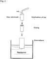
- ink composed of carbon powder containing a core particle supported thereon and a suitable dispersion medium is prepared, the ink is applied homogeneously to a disk electrode and dried, then the electrode is immersed in an electrolytic solution, followed by electrolysis (see Fig. 2 ).
- the core particle acts as a working electrode to deposit copper on the core particle surface.
- copper and platinum are displaced by each other to form a platinum shell layer on the core particle surface upon contact of a platinum compound solution with the disc electrode.
- a small amount of the core particles are applied to the disc electrode and it is subjected to an electrolytic treatment.
- An object of manufacturing a catalyst according to the conventional Cu-UPD technique is aimed at obtaining a catalyst having a satisfactory activity while decreasing the amount of platinum used, and the object has been sufficiently achieved.
- the amount of the catalyst manufactured per manufacture is, however, small and results in inefficient manufacturing in a method comprising applying a small amount of the core particles to the disc electrode and performing an electrolytic step in the manner described above. This method is a laboratorial manufacturing method and is not suitable for industrial manufacturing.
- the present invention has been made under the above circumstances. And with respect to a method of manufacturing a catalyst in which a catalytic particle having a core/shell structure is formed according to the Cu-UPD technique, the present invention provides one in which manufacturing efficiency is improved so as to be capable of mass production and a catalyst having also a satisfactory catalytic activity can be manufactured.
- the present inventors have investigated to optimize the platinum displacement step following the copper layer formation as an approach to solution of the problem described above. This is intended that the catalyst particle having the core/shell structure, being a final goal, can be manufactured, even if a somehow heterogeneous copper layer is formed by relaxation of strictness in the potential control in the electrolytic treatment step, so far as the following displacement by platinum is performed effectively. Then, it has been considered that relaxation of strictness in the potential control in the electrolytic treatment step can lead to enhancement of the throughput, and thereby can enhance the overall manufacturing efficiency. Accordingly, the present inventors have further investigated to find that addition of citric acid to the reaction system can lead to formation of an effective platinum layer in the displacement reaction step for the formation of the platinum layer.
- the present invention to solve the problem described above is a method according to claim 1 of manufacturing a catalyst including a catalytic particle supported on a carrier, the catalytic particle having a core/shell structure including: a shell layer containing platinum; and a core particle covered with the shell layer and containing a metal other than platinum.
- the method comprises the steps of: subjecting the carrier supporting the core particle to electrolysis in a copper ion-containing electrolytic solution, thereby depositing copper on a core particle surface, as an electrolytic treating step; and bringing a platinum compound solution into contact with the copper-deposited core particle to displace the copper on the core particle surface by platinum, thereby forming the shell layer comprising platinum, as a displacement reaction step, and the platinum compound solution in the displacement reaction step contains citric acid.
- the present invention is characterized by improving on the step for platinum displacement following the copper layer formation on the core particle, with regard to the Cu-UPD technique.
- This improvement is to perform the treatment in a state where citric acid is added to the platinum compound solution, thereby exhibiting an effect of enhancing a coverage with platinum on the core particle surface.
- Copper is to be directly displaced by platinum in the conventional platinum displacement step without citric acid addition.
- the displacement reaction follows a reaction mechanism where the citric acid mediates the displacement reaction between the copper and platinum, i.e., the copper and citric acid are displaced by each other and subsequently the citric acid and platinum are displaced by each other, or alternatively that platinum ion in the platinum compound solution forms a platinum-citric acid complex to change reduction potential thereof.
- the present invention will be explained in more detail below.
- the step of manufacturing a catalyst by the Cu-UPD technique includes: providing a core particle supported on a carrier; covering the core particle surface with a copper layer as an electrolytic treatment step; and displacing the copper on the core particle surface by platinum, thereby forming a platinum shell layer as a displacement reaction step.
- the core particle comprises a metal other than platinum.
- a metal palladium, iridium, rhodium, ruthenium, gold or an alloy thereof can be applied, and preferably palladium or a palladium alloy is applied.
- Palladium is suitable for the core particle because it has excellent chemical stability and also can improve an activity of the catalyst.
- a palladium alloy a palladium-nickel alloy, palladium-copper alloy, palladium-cobalt alloy, or palladium gold alloy can be applied. These palladium alloys can improve the activity of the catalyst more.
- a concentration of the additional element e.g., nickel or copper, is preferably 1/1 or more and 1/12 or less as a molar ratio of additional element:palladium when a palladium alloy is applied.
- an average particle diameter of the core particles is preferably 2nm or more and 50nm or less.
- the core particles are treated in a state where the core particles are supported on a carrier in the present invention.
- a carrier electrically conductive materials usually used for carriers of catalysts including, for example, electrically conductive carbon powder, electrically conductive ceramic powder can be applied.
- a method for forming the core particle on the carrier is not particularly limited and a known technique may be utilized. By way of example, a carrier is immersed in a solution of a metallic compound of a metal containing the core particle and the resultant material is reduced to be able to form the fine core particles.
- the alloy when an alloy is employed for the core particle, the alloy can be formed in the following procedure; the metal particle manufactured in the manner described above is immersed in a solution of a compound of a metal to be the additional element of the alloy, then the resultant material is reduced, followed by a heat treatment, or alternatively the carrier is immersed in a solution of compounds of two or more metals comprising the core particle, then the resultant material is reduced, followed by a heat treatment.
- the copper layer is electrolytically deposited on the particle surface in the electrolytic treatment step.
- the electrolytic treatment is a treatment where the core particles are arranged to the working electrode side and steady potential is applied thereto, thereby copper is deposited from the electrolytic solution.
- aspects for this enhanced throughput may include a state where the core particles (carrier supporting the core particles) are laminated to the electrode (working electrode). Even when the core particles are not fitted closely as are in the applied and dried state in the conventional method, the core particles can be electrolyzed via the carrier. Even though the potential of each individual core particle exhibits somewhat heterogeneity in that state, the catalytic particle having the core/shell structure can be finally formed in the present invention.
- the electrolytic deposition is performed in an electrolysis vessel housing an electrolytic solution.
- bottom part of the electrolysis vessel is composed of an electrically conductive material, which is made to be the working electrode, and core particles are laminated thereto, thereby a large amount of the core particles can be treated.
- an electrolysis vessel capacity also can be increased in the present invention and catalyst manufacturing is possible in an electrolysis vessel of 1-50 L, in which industrial manufacturing is supposed to be performed.
- the electrolytic solution in the electrolytic treatment is a copper compound solution and is not particularly limited so far as it is generally considered to be useful for Cu-UPD.
- Preferred specific examples of used copper compounds include copper sulfate, copper nitrate, copper chloride, copper chlorite, copper perchlorate, copper oxalate, and the like.
- Potential control conditions for the electrolytic deposition are adjusted depending on the kinds of metal of the core particle.
- the potential is fixed at 0.35-0.40 V (vs. RHE) and the potential fixing time is 1 hour or more and 10 hour or less in the electrolysis conditions.
- the dissolved oxygen content in the electrolytic solution is made 1 ppm or less in this electrolytic treatment step. This is because high dissolved oxygen content may result in oxidation and dissolution of the deposited copper and it can be a hindrance to the subsequent displacement reaction with platinum.
- usual bubbling of inert gas e.g., nitrogen
- Bubbling of inert gas is performed for 4-48 hours within a closed space where the oxygen concentration has been reduced (preferably 0 ppm) as a preferred pretreatment for decreasing the dissolved oxygen content.
- the dissolved oxygen content in the electrolytic solution can be made 1 ppm or less in this manner.
- the core particle having the copper layer formed is formed through the electrolytic treatment step described above, then the platinum compound solution is brought into contact with the core particle to cause displacement between the copper and platinum, thereby the platinum shell layer is formed.
- This displacement treatment can be conducted continuously in succession to the electrolytic deposition step by means of addition of the platinum compound solution into the electrolysis vessel.
- the core particles may be taken out from the electrolysis vessel and immersed in the platinum compound solution.
- the platinum compound solution is not particularly limited, and preferred is a solution of chloroplatinic acid, potassium chloroplatinate, tetraammineplatinum chloride, or diamminedinitritoplatinum nitric acid, and particularly preferred is a solution of potassium chloroplatinate.
- the amount of the platinum compound in the solution is preferably from an equivalent quantity to quadruple quantity on the basis of the necessary number of moles of platinum compound calculated from Cu-UPD.
- citric acid may be added to the platinum compound solution in advance, and then the platinum solution may be brought into contact with the core particle, or alternatively, citric acid may be brought into contact with the core particle, and subsequently the platinum compound may be added.
- the amount (number of moles) of citric acid added is preferably tenfold or more and 40-fold or less on the basis of the number of moles of the platinum compound. This is because a coverage with the platinum shell is decreased when the amount of citric acid is small. An amount of citric acid exceeding 40-fold is not preferred as the citric acid covers the platinum shell, thereby decreasing the catalytic activity.
- a treating period of time in the platinum displacement reaction it is preferable to ensure 30 minutes or more.
- a treating temperature particular control is not required and the treatment can be performed at a normal temperature.
- the catalyst having the core/shell structure comprising the platinum shell layer is formed through the platinum displacement step described above.
- the catalyst can be the one in which the catalytic particle having the core/shell structure is supported on the carrier when the step is performed in the state where the core particle is supported on the carrier.
- it is preferable to suitably perform washing and drying after formation of the platinum shell layer.
- the present invention is to optimize the platinum displacement treatment step with respect to a method of manufacturing a catalyst according to the Cu-UPD technique including an electrolytic treatment step and platinum displacement treatment step, thereby relaxing the strict treating conditions in the electrolytic treatment step to achieve an enhanced throughput.
- a catalytic particle having a core/shell structure can be efficiently manufactured.
- the catalyst manufactured according to the present invention also exhibits a satisfactory activity, and thus, is excellent in balance between a cost reduction effect due to reduction in the amount of platinum used and improved catalytic performance.
- a catalyst containing supported catalytic particle having a core/shell structure where palladium is employed as the core particle was manufactured, and then activity thereof was evaluated.
- 35 g of carbon powder (trade name: Ketjen Black EC, specific surface area: 800 g/m 3 ), which was to be the carrier of the catalyst, was immersed in a palladium chloride solution (amount of Pd, 15 g (0.028 mol)), then the solution was neutralized with sodium carbonate.
- the resultant material was subjected to a reduction treatment with sodium formate to produce carbon powder supporting a palladium particle which was to be the core particle.
- the electrolysis apparatus used in the present embodiment is shown in Figure 1 .
- the electrolysis apparatus shown in Figure 1 is equipped with a counter electrode tube having platinum mesh as a counter electrode and reference electrode inserted in an electrolysis vessel housing an electrolytic solution.
- the bottom part of the electrolysis vessel is composed of carbon blocks which act as a working electrode.
- the counter electrode, reference electrode and working electrode are connected to a potential control device.
- the amount of the catalyst obtained in the manufacturing step described above is 10 g. This amount manufactured shows that 100000-fold or more amount of the catalyst can be manufactured in one step on the basis of that in the conventional Cu-UPD technique ( ⁇ g order).
- Comparative Examples 1, 2 Commercially available catalysts containing a platinum particle and platinum alloy particle, respectively, were provided for the comparison with the catalyst containing the supported catalytic particle having the core/shell structure.
- the provided catalysts are a platinum catalyst (trade name: TEC10E50E) and platinum-cobalt catalyst (trade name: TEC36E52).
- the evaluation method employed is to investigate an oxygen reduction activity while rotating a rotary disk electrode with 8 ⁇ g of a catalyst applied thereto in an electrolytic solution.
- Flowing oxygen reduction currents were determined for a range of 0.1 V-1.0 V at a sweeping rate of 5 mV/s, while this electrode was rotated at each steady rate (1000 rpm, 1250 rpm, 1500 rpm, 1750 rpm, 2000 rpm, 2250 rpm, 2500 rpm) in an electrolytic solution saturated with oxygen.
- Table 1 illustrates that the catalyst manufactured in the present embodiment exhibits an extremely higher oxygen reduction activity in comparison with the platinum catalyst and platinum-cobalt catalyst of Comparative Examples.
- the manufacturing method of the present embodiment can be confirmed to be satisfactory also from a characteristic view point of the manufactured catalyst.
- Second Embodiment In this embodiment, catalysts were manufactured while the amount of citric acid added in the displacement reaction step following the electrolytic treatment step was varied. Palladium-nickel alloy was employed as the core particle.
- the same carbon powder as used in the First Embodiment which was to be a carrier was immersed in a solution of palladium nitrate (amount of Pd, 53 g (0.50 mol)) and nickel nitrate (amount of Ni, 176 g (3.0 mol)), then the solution was neutralized with sodium hydroxide. Then, a particle comprising a palladium-nickel alloy was formed on the carbon powder by means of a heat treatment.
- this carrier was immersed in 0.5 M sulfuric acid (80°C) to remove the nickel.
- 0.5 M sulfuric acid 80°C
- Such formation of the palladium-nickel alloy particle and removal of the nickel are performed in order to form pores on the alloy particle surface due to elution of the nickel, thereby enhancing the surface area and activity thereof.
- the amount of citric acid added is preferably a tenfold to 40-fold amount.
- the present invention is to optimize the platinum displacement treatment step in a method of manufacturing a catalyst according to the Cu-UPD technique, thereby achieving an enhanced amount of the catalyst produced.
- a catalyst having a core/shell structure which exhibits a satisfactory activity can be efficiently manufactured, and also a cost reduction effect due to reduction in the amount of platinum used can be expected.
Landscapes
- Chemical & Material Sciences (AREA)
- Engineering & Computer Science (AREA)
- Chemical Kinetics & Catalysis (AREA)
- Materials Engineering (AREA)
- Organic Chemistry (AREA)
- Electrochemistry (AREA)
- General Chemical & Material Sciences (AREA)
- Metallurgy (AREA)
- Manufacturing & Machinery (AREA)
- Plasma & Fusion (AREA)
- Toxicology (AREA)
- Health & Medical Sciences (AREA)
- Physics & Mathematics (AREA)
- Composite Materials (AREA)
- Mechanical Engineering (AREA)
- Catalysts (AREA)
- Inert Electrodes (AREA)
- Fuel Cell (AREA)
Applications Claiming Priority (2)
| Application Number | Priority Date | Filing Date | Title |
|---|---|---|---|
| JP2015046360A JP6270759B2 (ja) | 2015-03-09 | 2015-03-09 | コア/シェル構造の触媒粒子が担持された触媒の製造方法 |
| PCT/JP2016/056353 WO2016143618A1 (ja) | 2015-03-09 | 2016-03-02 | コア/シェル構造の触媒粒子が担持された触媒の製造方法 |
Publications (3)
| Publication Number | Publication Date |
|---|---|
| EP3269447A1 EP3269447A1 (en) | 2018-01-17 |
| EP3269447A4 EP3269447A4 (en) | 2019-01-02 |
| EP3269447B1 true EP3269447B1 (en) | 2020-01-08 |
Family
ID=56880486
Family Applications (1)
| Application Number | Title | Priority Date | Filing Date |
|---|---|---|---|
| EP16761588.9A Active EP3269447B1 (en) | 2015-03-09 | 2016-03-02 | Method for producing catalyst wherein catalyst particles having core/shell structure are supported |
Country Status (7)
| Country | Link |
|---|---|
| US (1) | US10497942B2 (enExample) |
| EP (1) | EP3269447B1 (enExample) |
| JP (1) | JP6270759B2 (enExample) |
| KR (1) | KR101963068B1 (enExample) |
| CN (1) | CN107405604B (enExample) |
| TW (1) | TWI597099B (enExample) |
| WO (1) | WO2016143618A1 (enExample) |
Families Citing this family (4)
| Publication number | Priority date | Publication date | Assignee | Title |
|---|---|---|---|---|
| KR101802098B1 (ko) | 2016-12-27 | 2017-11-28 | 인천대학교 산학협력단 | 양파구조의 이원계 금속 촉매 제조방법 |
| KR102225379B1 (ko) * | 2018-11-27 | 2021-03-10 | 한국에너지기술연구원 | 연속 반응기 타입의 코어-쉘 촉매 전극 제조장치 및 그 제조방법 |
| CN113394417B (zh) * | 2021-06-07 | 2022-06-14 | 福州大学 | 一种铜镍铂三层核壳结构催化剂及其制备方法和应用 |
| CN117258823B (zh) * | 2023-09-21 | 2025-12-09 | 中国工程物理研究院材料研究所 | 一种基于阴极腐蚀现象制备单原子催化剂的方法 |
Family Cites Families (11)
| Publication number | Priority date | Publication date | Assignee | Title |
|---|---|---|---|---|
| US7507495B2 (en) | 2004-12-22 | 2009-03-24 | Brookhaven Science Associates, Llc | Hydrogen absorption induced metal deposition on palladium and palladium-alloy particles |
| DE112010005260T5 (de) | 2010-02-12 | 2013-05-02 | Utc Power Corporation | Platin-Monoschicht auf Legierungs-Nanopartikeln mit hoher Oberflächenfläche und Herstellungsverfahren |
| JP5776102B2 (ja) * | 2011-02-22 | 2015-09-09 | バラード パワー システムズ インコーポレイテッド | 白金原子の原子層を有する触媒を形成する方法 |
| US9260789B2 (en) * | 2012-05-14 | 2016-02-16 | United Technologies Corporation | Underpotential depositon of metal monolayers from ionic liquids |
| JP2014213212A (ja) * | 2013-04-22 | 2014-11-17 | トヨタ自動車株式会社 | コアシェル触媒粒子の製造方法 |
| JP2014229516A (ja) * | 2013-05-23 | 2014-12-08 | トヨタ自動車株式会社 | 燃料電池用触媒の製造方法 |
| JP5929942B2 (ja) * | 2014-02-14 | 2016-06-08 | トヨタ自動車株式会社 | カーボン担持触媒 |
| JP6075305B2 (ja) * | 2014-02-14 | 2017-02-08 | トヨタ自動車株式会社 | コアシェル触媒粒子の製造方法 |
| JP6020508B2 (ja) * | 2014-04-18 | 2016-11-02 | トヨタ自動車株式会社 | 触媒微粒子及びカーボン担持触媒の各製造方法 |
| US20150299886A1 (en) * | 2014-04-18 | 2015-10-22 | Lam Research Corporation | Method and apparatus for preparing a substrate with a semi-noble metal layer |
| JP2015225064A (ja) * | 2014-05-30 | 2015-12-14 | トヨタ自動車株式会社 | コアシェル触媒のシェルを形成する単原子膜の積層数の測定方法 |
-
2015
- 2015-03-09 JP JP2015046360A patent/JP6270759B2/ja active Active
-
2016
- 2016-03-02 CN CN201680014687.1A patent/CN107405604B/zh active Active
- 2016-03-02 US US15/548,193 patent/US10497942B2/en active Active
- 2016-03-02 EP EP16761588.9A patent/EP3269447B1/en active Active
- 2016-03-02 KR KR1020177022787A patent/KR101963068B1/ko active Active
- 2016-03-02 WO PCT/JP2016/056353 patent/WO2016143618A1/ja not_active Ceased
- 2016-03-03 TW TW105106507A patent/TWI597099B/zh active
Non-Patent Citations (1)
| Title |
|---|
| None * |
Also Published As
| Publication number | Publication date |
|---|---|
| CN107405604A (zh) | 2017-11-28 |
| JP2016165675A (ja) | 2016-09-15 |
| EP3269447A4 (en) | 2019-01-02 |
| JP6270759B2 (ja) | 2018-01-31 |
| US20180034062A1 (en) | 2018-02-01 |
| KR20170105570A (ko) | 2017-09-19 |
| US10497942B2 (en) | 2019-12-03 |
| WO2016143618A1 (ja) | 2016-09-15 |
| TW201641160A (zh) | 2016-12-01 |
| EP3269447A1 (en) | 2018-01-17 |
| TWI597099B (zh) | 2017-09-01 |
| CN107405604B (zh) | 2020-05-12 |
| KR101963068B1 (ko) | 2019-03-27 |
Similar Documents
| Publication | Publication Date | Title |
|---|---|---|
| KR102056527B1 (ko) | 연료 전지용 전극 촉매, 및 촉매를 활성화시키는 방법 | |
| US20150318560A1 (en) | Method for producing a catalyst for fuel cells | |
| JP5456797B2 (ja) | 燃料電池用電極触媒 | |
| EP3532655A1 (en) | Electrocatalyst composition comprising noble metal oxide supported on tin oxide | |
| EP3269447B1 (en) | Method for producing catalyst wherein catalyst particles having core/shell structure are supported | |
| KR20140012055A (ko) | 촉매 미립자, 카본 담지 촉매 미립자, 촉매 합제, 및 전극의 각 제조 방법 | |
| JP6075305B2 (ja) | コアシェル触媒粒子の製造方法 | |
| KR101670929B1 (ko) | 산소 발생 촉매, 전극 및 전기화학반응 시스템 | |
| JP5664370B2 (ja) | 触媒微粒子の製造方法 | |
| KR20160128951A (ko) | 산소 발생 촉매, 전극 및 전기화학반응 시스템 | |
| Gruzeł et al. | Conversion of bimetallic PtNi 3 nanopolyhedra to ternary PtNiSn nanoframes by galvanic replacement reaction | |
| WO2014136798A1 (ja) | 固体高分子形燃料電池カソード用の触媒およびそのような触媒の製造方法 | |
| JP5365231B2 (ja) | 導電性酸化物担体の製造方法 | |
| JP2014229516A (ja) | 燃料電池用触媒の製造方法 | |
| US9941521B2 (en) | Method for producing core-shell catalyst | |
| JP2014213212A (ja) | コアシェル触媒粒子の製造方法 | |
| TW201822885A (zh) | 生產可用於水氧化作用中的電催化劑之製程 | |
| Patra et al. | Synthesis of trimetallic Au@ Pb@ Pt core-shell nanoparticles and their electrocatalytic activity toward formic acid and methanol | |
| JP2012157833A (ja) | 触媒微粒子の製造方法、当該方法により製造される触媒微粒子、及び当該触媒微粒子を含む燃料電池用電極触媒 | |
| EP3614473A1 (en) | Catalyst for solid polymer fuel cell and manufacturing method therefor | |
| JP2014221448A (ja) | コアシェル触媒粒子の製造方法及びコアシェル触媒粒子 | |
| JP2015199002A (ja) | コアシェル触媒製造装置及びコアシェル触媒の製造方法 | |
| JP2015205233A (ja) | 触媒微粒子及びカーボン担持触媒の各製造方法 | |
| KR20080044324A (ko) | 귀금속 미립자 및 그 제조 방법 | |
| JP2016135465A (ja) | コアシェル触媒の製造方法 |
Legal Events
| Date | Code | Title | Description |
|---|---|---|---|
| STAA | Information on the status of an ep patent application or granted ep patent |
Free format text: STATUS: THE INTERNATIONAL PUBLICATION HAS BEEN MADE |
|
| PUAI | Public reference made under article 153(3) epc to a published international application that has entered the european phase |
Free format text: ORIGINAL CODE: 0009012 |
|
| STAA | Information on the status of an ep patent application or granted ep patent |
Free format text: STATUS: REQUEST FOR EXAMINATION WAS MADE |
|
| 17P | Request for examination filed |
Effective date: 20171005 |
|
| AK | Designated contracting states |
Kind code of ref document: A1 Designated state(s): AL AT BE BG CH CY CZ DE DK EE ES FI FR GB GR HR HU IE IS IT LI LT LU LV MC MK MT NL NO PL PT RO RS SE SI SK SM TR |
|
| AX | Request for extension of the european patent |
Extension state: BA ME |
|
| DAV | Request for validation of the european patent (deleted) | ||
| DAX | Request for extension of the european patent (deleted) | ||
| A4 | Supplementary search report drawn up and despatched |
Effective date: 20181203 |
|
| RIC1 | Information provided on ipc code assigned before grant |
Ipc: B01J 37/34 20060101AFI20181123BHEP Ipc: H01M 4/90 20060101ALI20181123BHEP Ipc: H01M 8/10 20160101ALI20181123BHEP Ipc: B01J 23/44 20060101ALI20181123BHEP Ipc: H01M 4/88 20060101ALI20181123BHEP Ipc: B01J 37/02 20060101ALI20181123BHEP Ipc: B01J 35/00 20060101ALI20181123BHEP Ipc: H01M 4/92 20060101ALI20181123BHEP Ipc: H01M 4/86 20060101ALI20181123BHEP |
|
| REG | Reference to a national code |
Ref country code: DE Ref legal event code: R079 Ref document number: 602016027887 Country of ref document: DE Free format text: PREVIOUS MAIN CLASS: B01J0023440000 Ipc: B01J0037340000 |
|
| GRAP | Despatch of communication of intention to grant a patent |
Free format text: ORIGINAL CODE: EPIDOSNIGR1 |
|
| STAA | Information on the status of an ep patent application or granted ep patent |
Free format text: STATUS: GRANT OF PATENT IS INTENDED |
|
| RIC1 | Information provided on ipc code assigned before grant |
Ipc: H01M 4/92 20060101ALI20190628BHEP Ipc: B01J 35/00 20060101ALI20190628BHEP Ipc: H01M 4/90 20060101ALI20190628BHEP Ipc: B01J 37/34 20060101AFI20190628BHEP Ipc: B01J 23/44 20060101ALI20190628BHEP Ipc: H01M 4/88 20060101ALI20190628BHEP Ipc: B01J 37/02 20060101ALI20190628BHEP Ipc: H01M 4/86 20060101ALI20190628BHEP Ipc: H01M 8/10 20160101ALI20190628BHEP |
|
| INTG | Intention to grant announced |
Effective date: 20190806 |
|
| GRAS | Grant fee paid |
Free format text: ORIGINAL CODE: EPIDOSNIGR3 |
|
| GRAA | (expected) grant |
Free format text: ORIGINAL CODE: 0009210 |
|
| STAA | Information on the status of an ep patent application or granted ep patent |
Free format text: STATUS: THE PATENT HAS BEEN GRANTED |
|
| AK | Designated contracting states |
Kind code of ref document: B1 Designated state(s): AL AT BE BG CH CY CZ DE DK EE ES FI FR GB GR HR HU IE IS IT LI LT LU LV MC MK MT NL NO PL PT RO RS SE SI SK SM TR |
|
| REG | Reference to a national code |
Ref country code: GB Ref legal event code: FG4D |
|
| REG | Reference to a national code |
Ref country code: CH Ref legal event code: EP |
|
| REG | Reference to a national code |
Ref country code: DE Ref legal event code: R096 Ref document number: 602016027887 Country of ref document: DE |
|
| REG | Reference to a national code |
Ref country code: IE Ref legal event code: FG4D |
|
| REG | Reference to a national code |
Ref country code: AT Ref legal event code: REF Ref document number: 1222022 Country of ref document: AT Kind code of ref document: T Effective date: 20200215 |
|
| REG | Reference to a national code |
Ref country code: NL Ref legal event code: MP Effective date: 20200108 |
|
| REG | Reference to a national code |
Ref country code: LT Ref legal event code: MG4D |
|
| PG25 | Lapsed in a contracting state [announced via postgrant information from national office to epo] |
Ref country code: NO Free format text: LAPSE BECAUSE OF FAILURE TO SUBMIT A TRANSLATION OF THE DESCRIPTION OR TO PAY THE FEE WITHIN THE PRESCRIBED TIME-LIMIT Effective date: 20200408 Ref country code: PT Free format text: LAPSE BECAUSE OF FAILURE TO SUBMIT A TRANSLATION OF THE DESCRIPTION OR TO PAY THE FEE WITHIN THE PRESCRIBED TIME-LIMIT Effective date: 20200531 Ref country code: RS Free format text: LAPSE BECAUSE OF FAILURE TO SUBMIT A TRANSLATION OF THE DESCRIPTION OR TO PAY THE FEE WITHIN THE PRESCRIBED TIME-LIMIT Effective date: 20200108 Ref country code: FI Free format text: LAPSE BECAUSE OF FAILURE TO SUBMIT A TRANSLATION OF THE DESCRIPTION OR TO PAY THE FEE WITHIN THE PRESCRIBED TIME-LIMIT Effective date: 20200108 Ref country code: NL Free format text: LAPSE BECAUSE OF FAILURE TO SUBMIT A TRANSLATION OF THE DESCRIPTION OR TO PAY THE FEE WITHIN THE PRESCRIBED TIME-LIMIT Effective date: 20200108 Ref country code: LT Free format text: LAPSE BECAUSE OF FAILURE TO SUBMIT A TRANSLATION OF THE DESCRIPTION OR TO PAY THE FEE WITHIN THE PRESCRIBED TIME-LIMIT Effective date: 20200108 |
|
| PG25 | Lapsed in a contracting state [announced via postgrant information from national office to epo] |
Ref country code: HR Free format text: LAPSE BECAUSE OF FAILURE TO SUBMIT A TRANSLATION OF THE DESCRIPTION OR TO PAY THE FEE WITHIN THE PRESCRIBED TIME-LIMIT Effective date: 20200108 Ref country code: LV Free format text: LAPSE BECAUSE OF FAILURE TO SUBMIT A TRANSLATION OF THE DESCRIPTION OR TO PAY THE FEE WITHIN THE PRESCRIBED TIME-LIMIT Effective date: 20200108 Ref country code: SE Free format text: LAPSE BECAUSE OF FAILURE TO SUBMIT A TRANSLATION OF THE DESCRIPTION OR TO PAY THE FEE WITHIN THE PRESCRIBED TIME-LIMIT Effective date: 20200108 Ref country code: GR Free format text: LAPSE BECAUSE OF FAILURE TO SUBMIT A TRANSLATION OF THE DESCRIPTION OR TO PAY THE FEE WITHIN THE PRESCRIBED TIME-LIMIT Effective date: 20200409 Ref country code: BG Free format text: LAPSE BECAUSE OF FAILURE TO SUBMIT A TRANSLATION OF THE DESCRIPTION OR TO PAY THE FEE WITHIN THE PRESCRIBED TIME-LIMIT Effective date: 20200408 Ref country code: IS Free format text: LAPSE BECAUSE OF FAILURE TO SUBMIT A TRANSLATION OF THE DESCRIPTION OR TO PAY THE FEE WITHIN THE PRESCRIBED TIME-LIMIT Effective date: 20200508 |
|
| REG | Reference to a national code |
Ref country code: DE Ref legal event code: R097 Ref document number: 602016027887 Country of ref document: DE |
|
| PG25 | Lapsed in a contracting state [announced via postgrant information from national office to epo] |
Ref country code: RO Free format text: LAPSE BECAUSE OF FAILURE TO SUBMIT A TRANSLATION OF THE DESCRIPTION OR TO PAY THE FEE WITHIN THE PRESCRIBED TIME-LIMIT Effective date: 20200108 Ref country code: CZ Free format text: LAPSE BECAUSE OF FAILURE TO SUBMIT A TRANSLATION OF THE DESCRIPTION OR TO PAY THE FEE WITHIN THE PRESCRIBED TIME-LIMIT Effective date: 20200108 Ref country code: SK Free format text: LAPSE BECAUSE OF FAILURE TO SUBMIT A TRANSLATION OF THE DESCRIPTION OR TO PAY THE FEE WITHIN THE PRESCRIBED TIME-LIMIT Effective date: 20200108 Ref country code: MC Free format text: LAPSE BECAUSE OF FAILURE TO SUBMIT A TRANSLATION OF THE DESCRIPTION OR TO PAY THE FEE WITHIN THE PRESCRIBED TIME-LIMIT Effective date: 20200108 Ref country code: DK Free format text: LAPSE BECAUSE OF FAILURE TO SUBMIT A TRANSLATION OF THE DESCRIPTION OR TO PAY THE FEE WITHIN THE PRESCRIBED TIME-LIMIT Effective date: 20200108 Ref country code: ES Free format text: LAPSE BECAUSE OF FAILURE TO SUBMIT A TRANSLATION OF THE DESCRIPTION OR TO PAY THE FEE WITHIN THE PRESCRIBED TIME-LIMIT Effective date: 20200108 Ref country code: SM Free format text: LAPSE BECAUSE OF FAILURE TO SUBMIT A TRANSLATION OF THE DESCRIPTION OR TO PAY THE FEE WITHIN THE PRESCRIBED TIME-LIMIT Effective date: 20200108 Ref country code: EE Free format text: LAPSE BECAUSE OF FAILURE TO SUBMIT A TRANSLATION OF THE DESCRIPTION OR TO PAY THE FEE WITHIN THE PRESCRIBED TIME-LIMIT Effective date: 20200108 |
|
| REG | Reference to a national code |
Ref country code: CH Ref legal event code: PL |
|
| PLBE | No opposition filed within time limit |
Free format text: ORIGINAL CODE: 0009261 |
|
| STAA | Information on the status of an ep patent application or granted ep patent |
Free format text: STATUS: NO OPPOSITION FILED WITHIN TIME LIMIT |
|
| REG | Reference to a national code |
Ref country code: AT Ref legal event code: MK05 Ref document number: 1222022 Country of ref document: AT Kind code of ref document: T Effective date: 20200108 |
|
| 26N | No opposition filed |
Effective date: 20201009 |
|
| REG | Reference to a national code |
Ref country code: BE Ref legal event code: MM Effective date: 20200331 |
|
| PG25 | Lapsed in a contracting state [announced via postgrant information from national office to epo] |
Ref country code: LU Free format text: LAPSE BECAUSE OF NON-PAYMENT OF DUE FEES Effective date: 20200302 |
|
| PG25 | Lapsed in a contracting state [announced via postgrant information from national office to epo] |
Ref country code: AT Free format text: LAPSE BECAUSE OF FAILURE TO SUBMIT A TRANSLATION OF THE DESCRIPTION OR TO PAY THE FEE WITHIN THE PRESCRIBED TIME-LIMIT Effective date: 20200108 Ref country code: IE Free format text: LAPSE BECAUSE OF NON-PAYMENT OF DUE FEES Effective date: 20200302 Ref country code: IT Free format text: LAPSE BECAUSE OF FAILURE TO SUBMIT A TRANSLATION OF THE DESCRIPTION OR TO PAY THE FEE WITHIN THE PRESCRIBED TIME-LIMIT Effective date: 20200108 Ref country code: LI Free format text: LAPSE BECAUSE OF NON-PAYMENT OF DUE FEES Effective date: 20200331 Ref country code: CH Free format text: LAPSE BECAUSE OF NON-PAYMENT OF DUE FEES Effective date: 20200331 |
|
| PG25 | Lapsed in a contracting state [announced via postgrant information from national office to epo] |
Ref country code: PL Free format text: LAPSE BECAUSE OF FAILURE TO SUBMIT A TRANSLATION OF THE DESCRIPTION OR TO PAY THE FEE WITHIN THE PRESCRIBED TIME-LIMIT Effective date: 20200108 Ref country code: SI Free format text: LAPSE BECAUSE OF FAILURE TO SUBMIT A TRANSLATION OF THE DESCRIPTION OR TO PAY THE FEE WITHIN THE PRESCRIBED TIME-LIMIT Effective date: 20200108 Ref country code: BE Free format text: LAPSE BECAUSE OF NON-PAYMENT OF DUE FEES Effective date: 20200331 |
|
| PG25 | Lapsed in a contracting state [announced via postgrant information from national office to epo] |
Ref country code: TR Free format text: LAPSE BECAUSE OF FAILURE TO SUBMIT A TRANSLATION OF THE DESCRIPTION OR TO PAY THE FEE WITHIN THE PRESCRIBED TIME-LIMIT Effective date: 20200108 Ref country code: MT Free format text: LAPSE BECAUSE OF FAILURE TO SUBMIT A TRANSLATION OF THE DESCRIPTION OR TO PAY THE FEE WITHIN THE PRESCRIBED TIME-LIMIT Effective date: 20200108 Ref country code: CY Free format text: LAPSE BECAUSE OF FAILURE TO SUBMIT A TRANSLATION OF THE DESCRIPTION OR TO PAY THE FEE WITHIN THE PRESCRIBED TIME-LIMIT Effective date: 20200108 |
|
| PG25 | Lapsed in a contracting state [announced via postgrant information from national office to epo] |
Ref country code: MK Free format text: LAPSE BECAUSE OF FAILURE TO SUBMIT A TRANSLATION OF THE DESCRIPTION OR TO PAY THE FEE WITHIN THE PRESCRIBED TIME-LIMIT Effective date: 20200108 Ref country code: AL Free format text: LAPSE BECAUSE OF FAILURE TO SUBMIT A TRANSLATION OF THE DESCRIPTION OR TO PAY THE FEE WITHIN THE PRESCRIBED TIME-LIMIT Effective date: 20200108 |
|
| P01 | Opt-out of the competence of the unified patent court (upc) registered |
Effective date: 20231201 |
|
| PGFP | Annual fee paid to national office [announced via postgrant information from national office to epo] |
Ref country code: DE Payment date: 20250319 Year of fee payment: 10 |
|
| PGFP | Annual fee paid to national office [announced via postgrant information from national office to epo] |
Ref country code: FR Payment date: 20250325 Year of fee payment: 10 |
|
| PGFP | Annual fee paid to national office [announced via postgrant information from national office to epo] |
Ref country code: GB Payment date: 20250321 Year of fee payment: 10 |