EP3268301B1 - Mechanismus für den transfer einer last - Google Patents
Mechanismus für den transfer einer last Download PDFInfo
- Publication number
- EP3268301B1 EP3268301B1 EP16712973.3A EP16712973A EP3268301B1 EP 3268301 B1 EP3268301 B1 EP 3268301B1 EP 16712973 A EP16712973 A EP 16712973A EP 3268301 B1 EP3268301 B1 EP 3268301B1
- Authority
- EP
- European Patent Office
- Prior art keywords
- telescopic rails
- rails
- lift
- lift truck
- carriage
- Prior art date
- Legal status (The legal status is an assumption and is not a legal conclusion. Google has not performed a legal analysis and makes no representation as to the accuracy of the status listed.)
- Active
Links
Images






Classifications
-
- B—PERFORMING OPERATIONS; TRANSPORTING
- B65—CONVEYING; PACKING; STORING; HANDLING THIN OR FILAMENTARY MATERIAL
- B65G—TRANSPORT OR STORAGE DEVICES, e.g. CONVEYORS FOR LOADING OR TIPPING, SHOP CONVEYOR SYSTEMS OR PNEUMATIC TUBE CONVEYORS
- B65G1/00—Storing articles, individually or in orderly arrangement, in warehouses or magazines
- B65G1/02—Storage devices
- B65G1/04—Storage devices mechanical
- B65G1/0407—Storage devices mechanical using stacker cranes
- B65G1/0435—Storage devices mechanical using stacker cranes with pulling or pushing means on either stacking crane or stacking area
-
- B—PERFORMING OPERATIONS; TRANSPORTING
- B66—HOISTING; LIFTING; HAULING
- B66F—HOISTING, LIFTING, HAULING OR PUSHING, NOT OTHERWISE PROVIDED FOR, e.g. DEVICES WHICH APPLY A LIFTING OR PUSHING FORCE DIRECTLY TO THE SURFACE OF A LOAD
- B66F9/00—Devices for lifting or lowering bulky or heavy goods for loading or unloading purposes
- B66F9/06—Devices for lifting or lowering bulky or heavy goods for loading or unloading purposes movable, with their loads, on wheels or the like, e.g. fork-lift trucks
- B66F9/075—Constructional features or details
- B66F9/12—Platforms; Forks; Other load supporting or gripping members
- B66F9/14—Platforms; Forks; Other load supporting or gripping members laterally movable, e.g. swingable, for slewing or transverse movements
- B66F9/141—Platforms; Forks; Other load supporting or gripping members laterally movable, e.g. swingable, for slewing or transverse movements with shuttle-type movement
Definitions
- the present invention relates to a load transfer mechanism and in particular a load transfer mechanism for use with lift trucks to transfer pallets to and from racking.
- the mechanism according to the present invention may form a separate attachment for use with a lift truck.
- the lift truck when transferring a load from the lift truck to a racking system, the lift truck must be capable of balancing the load, as it is transferred into the racking system. This is normally achieved by means of counter weights which are mounted on the lift truck, remote from the lift mechanism upon which the load is carried. Even with this type of lift truck, in order to maximise the load handling capacity, the load must be transferred to the racking system by approaching the racking system at 90 degrees. This requires wide aisles between the rows of racking, significantly reducing the density of storage possible.
- One solution to this problem is to use an articulated truck in which the lift mechanism is pivoted with respect to the main body of the truck, so that the lift mechanism may be manoeuvred so that it approaches the racking at 90 degrees, in a narrower aisle.
- the mechanism according to the present invention increases the load handling performance of the lift truck.
- a load may be mounted on the secondary lift mechanism and raised to an appropriate level for transfer to a racking system, by the lift mechanism of the lift truck.
- the telescopic rails may then be extended laterally into the racking system and lowered by the lift mechanism of the lift truck, so that they engage the racking system.
- the secondary lift mechanism is adjusted to raise the load above the level of the racking and the carriage is then moved laterally along the telescopic rails, to move the load into the racking system, the load being supported on the telescopic rails by the lift mechanism of the lift truck at one end and by the racking system at the other end, so that there is no moment applied to the lift truck causing it to topple sideways.
- the load is lowered onto the racking system by means of the secondary lift mechanism.
- Loads may be removed from the racking system by first moving the telescopic rails into engagement with the racking system as described above, moving the carriage with the secondary lift mechanism lowered, to engage the load; lifting the load clear of the racking system by means of the secondary lift mechanism; moving the carriage and the load back along the telescopic rails to the lift mast of the lift truck; finally telescopic rails are moved out of engagement with the racking system and are retracted.
- the mechanism according to the present invention may be used with any suitable lift truck, for example support rail stackers, counterbalance trucks, reach trucks, articulated trucks, VNA turret trucks or stacker cranes.
- the mechanism may be used as the primary load bearing means of the lift truck or as an attachment that may replace the primary load bearing means or be mounted on the primary load bearing means.
- the movement of the telescopic rails between the extended and retracted positions; movement of the carriage along the telescopic rails and raising and lowering of the secondary lift mechanism may be achieved by mechanical, hydraulic, pneumatic or electrical means or any combination thereof, which may be independent of or integrated with the power systems of the lift truck.
- Control means including actuators and sensors are provided for sequencing the various stages of operation and prevent movement of the carriage and load along the telescopic rails until the rails are fully supported by the racking system.
- the accompanying drawings illustrate an attachment which is designed to be mounted on the forks of the main lift mechanism of a lift truck.
- the attachment described is designed for use with racking systems having front and rear parallel support beams which span between vertical uprights, the support beams being spaced horizontally so that pallets may be supported thereon adjacent their front and rear edges.
- the invention is furthermore described as used with two way pallets having top and bottom decking boards, secured laterally between parallel fore/aft extending stringers.
- the attachment may however be used with other forms of racking system and with other forms of pallet.
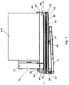
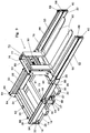
- the attachment 10 comprises a sub-frame 12, with a pair of parallel transversely extending side members 14.
- the side members 14 are connected by longitudinally extending cross members 16, 18, 20, cross members 16 and 20 being positions at opposite extremities of the side members 14 and cross member 18 being positioned intermediate of the cross members 16 and 20.
- the cross members 18 and 20 are of rectangular box section and are spaced apart, so that the forks of the main lift mechanism of the lift truck may engage in the tubular cross members 18, 20 to mount the attachment 10 to the lift truck.
- a pair of hinge formations 22 are provided on the cross member 16, one at each end of the cross member 16.
- a pair of transversely extending telescopic rails 24 are attached by the hinges 22 to the cross member 16 so that they overlie the side members 14.
- the telescopic rails 24 are free to pivot about hinges 22 from a position in which the extend downwardly towards the frame 12 from the hinged ends to the free ends, to a position in which they are tilted upwardly away from the frame, from the hinged ends to the free ends.
- the telescopic rails 24 each comprise an outer box section rail 30 with an inner box section rail 32, slidably located within the outer rail 30.
- the outer rails 30 are connected to hinge formations 22 of the frame 12 by hinge plates 28 which space the hinged ends of telescopic rails 24 from the side members 14 of frame 12.
- the outer rails 30 of the telescopic rails 24 are secured together, parallel to one another, adjacent the hinged ends, by cross members 33, 34.
- a pair of spaced strips 35 of plastics bearing material, for example Nylon 66, are provided longitudinally along the top and bottom walls of the inner rails 32, one strip 35 adjacent each edge of the top and bottom wall, the strips 35 slidably engaging the interior surface of the top and bottom walls of the outer rails 30.
- Blocks 36 of plastics bearing material, for example nylon 66, are secured to the outer side walls of the inner rails 32, adjacent the ends of inner rails 32 which engage the hinged ends of outer rails 30, to slidably engage the inner surface of the outer side wall of the outer rail 30.
- Flange formations 38 are provided on the upper surface of the outer rails 30 to provide a track for a carriage 50, to guide movement of the carriage 50 along the telescopic rails 24, when fully deployed.
- Double acting hydraulic rams 40 are mounted within the inner and outer rails 30, 32, the cylinder 41 of the ram 40 being secured to the outer rail 30, at the hinged end thereof, and the piston 42 of the ram 40 being secured to the inner member 32 at the end thereof remote from the hinged end of the telescopic rail 24.
- Brackets members 44 are secured to the outside of each side member 14 of the frame 12, intermediate of the cross members 18 and 20.
- a tilt ram 45 is mounted on each of the bracket members 44, the tilt rams 45 extending perpendicular to the side members 14 towards the telescopic rails 24.
- the tilt rams 45 are double acting rams, the piston of each ram 45 engaging an abutment plate 46 secured to the outer wall the adjacent outer rail 30.
- the rams 45 act to pivot the telescopic rails upwardly from the downwardly tilted position to the upwardly tilted position.
- the telescopic rails are however free to tilt upwardly away from the rams 45.
- a tie bolt 47 is secured to each bracket member 44 and extends parallel to the tilt ram 45.
- the tie bolts 47 extend through apertures 48 in the abutments plates 46 and a stop 49, with a rubber buffer, is provided at the free end of each tie bolts 47, so that engagement of the stops 49 against the abutment plates 46 will limit upward movement of the telescopic rails 24 relative to the frame 12.
- the carriage 50 comprises a pair of rectangular box section chassis members 52 which extend parallel to and in overlying relationship to the telescopic rails 24.
- the chassis members 52 are interconnected at the ends adjacent the hinged ends of the telescopic rails 24 by a box section cross member 54.
- the bottom walls of the box section chassis members 52, adjacent the ends of the chassis members, are cut away to form downwardly opening channel sections at the ends of the chassis members 52.
- Wheels 56, 58 are mounted for rotation within the channel sections at each end of the chassis members 52, wheels 56 for rotation about a common axis adjacent the end of the chassis members 52 at the end thereof adjacent the hinged end of the telescopic rails 24 and wheels 58 for rotation about a common axis of rotation adjacent the end of the chassis members 52 remote from the hinged end of the telescopic rails 24.
- the wheels 56 and 58 are positioned on the chassis members 52 so that they extend below the lower open edge of the channel section of the chassis members 52 and engage the upper surface of the outer rails 30, of the telescopic rails 24, between the flange formations 38.
- the wheels 56 and 58 are spaced apart such that when the attachment is in the retracted state as illustrated in figures 1 and 2 , wheels 56 will engage the upper surface of the outer rail 30 adjacent the hinged end of the telescopic rail 24, while the wheels 58 will engage end portions of the inner rail 32, which extend beyond the ends on the outer rails 30 when the telescopic rail 24 is fully retracted.
- the wheels 58 engage the upper surface of the inner rail 32, between the bearing strips 35.
- the wheels 56 and 58 are mounted on the chassis members 52 at different heights, to accommodate the difference in height of the upper surfaces of the inner and outer rails 30, 32.
- a double acting hydraulic ram 60 is located above one of the chassis members 52.
- the cylinders 62 of the ram 60 is secured to the outer rail 30 adjacent the hinged end of telescopic rails 24 by means of a bracket 64 and the piston 66 of the ram 60 is secured to a bracket 68 on the end chassis members 52 of the carriage 50 remote from the hinged end of the telescopic rail 24.
- a secondary lift mechanism 70 is secured to the cross member 54 of the carriage 50, centrally thereof.
- the secondary lift mechanism 70 comprises a pair of upstanding channel section beams 72, the channel section beams 72 opening towards one another.
- a carriage 74 is mounted between the channel section beams 72, the carriage 74 having a pair of side plates 76 with rollers bearings for engagement in opposed channels of the beams 72, whereby the carriage 74 is guided for vertical movement up and down the beams 72.
- a double acting hydraulic ram 78 acts between plate 54 and the carriage 74 to move the carriage up and down the beams 72.
- a pair of cross members 80 are provided on the carriage 74 by which a pair of forks 82 may be secured to the carriage 74 in known manner.
- the forks 82 are mounted on the carriage 74 such that; when the carriage 74 is in its lowermost position, the forks 82 do not extend below the lower surfaces of the inner rails 32 of telescopic rails 24, when the telescopic rails 24 are disposed horizontally; and when the carriage 74 is in its uppermost position, the forks will be above the level of the chassis members 52.
- Limit switches 84, 85 are provided to detect the extremes of movement of the telescopic rails 24; limit switches 86, 87 are provided to detect the extremes of movement of the tilt rams 45; limit switches 88, 89 are provided to detect the extremes of movement of the carriage 50; and limit switches 90, 91 are provided to detect the extremes of movement of the secondary lift mechanism 70.
- a two axis level sensor 92 is provided for sensing the plane of the telescopic rails 24. This level sensor will ensure that the extended telescopic rails 24 are disposed in the plane of the support surfaces of the front and rear beams 142, 144 of the racking system so that the rails 24 engage both the front and rear beams 142, 144.
- the level sensor 92 will nominally sense when the telescopic rails 24 are disposed in a horizontal plane, but may be calibrated to accommodate tolerance variations in the levels of the beams 142, 144.
- the limit switches 84, 85, 86, 87, 88, 89, 90, 91 and level sensor 92 all provide inputs to a programmable logic controller (PLC) 93, which controls a hydraulic circuit 100.
- Visual indication means 94 is also connected to the PLC 93 to indicate the position in the control cycle of the PLC 93.
- the attachment is provided with a battery power source to power the control system.
- Switch means 95 is also provided on the frame 12, on the underside thereof, to indicate engagement of the frame 12 with the floor or some other solid support platform from or to which a pallet is to be transferred.
- the hydraulic circuit 100 comprises a first hydraulic solenoid valve 102 which selectively connects each side the rail cylinders 40 to hydraulic line 110 or 112; a second hydraulic solenoid valve 104 which selectively connects each side the tilt cylinders 45 to hydraulic line 110 or 112; a third hydraulic solenoid valve 106 which selectively connects each side the cartridge cylinder 60 to hydraulic line 110 or 112; and a fourth hydraulic solenoid valve 108 which selectively connects each side the rail cylinders 40 to hydraulic line 110 or 112.
- the solenoid valve 108 is connected to each side of the lift cylinders 78 via a pilot operated check valve 114, which will ensure that the lift cylinders are hydraulically locked, when no hydraulic pressure is applied.
- a non-return valve 116 is provided in line 110 to prevent return flow from solenoid valves 102, 104 and 106, while a non-return valve 118 between solenoid valve 108 and line 112 prevents return flow from solenoid valve 108.
- the lines 110 and 112 of the hydraulic circuit of the attachment described above, are provided with connectors 120, 122 by which they may be connected to the lever operated spool valve 124 which controls the auxiliary hydraulic power take-off, for example a side shift take-off, from the hydraulic system of the fork lift truck.
- the lever 130 is pivoted about a fulcrum 132 and is connected to a control rod 134 which controls movement of the spool.
- the lever operated spool valve 124 selectively connects line 110 and 112 to a source 126 of hydraulic fluid under pressure, or to drain 128. With the lever 130 in the central neutral position, the lines 110 and 112 will be isolated from the hydraulic pressure source 126 and from the drain 128.
- the lever When the lever is pushed in direction A, the spool is moved to the right, connecting line 110 to the hydraulic pressure source 126 and line 112 to drain 128, thus connecting solenoid valves 102, 104 and 106 to the power source via line 110 and to drain via line 112.
- solenoid valve 108 While in this state solenoid valve 108 is connected to the hydraulic pressure source 126 by line 110, it is isolated from the drain 128 by the non-return valve 118.
- the lever 130 When the lever 130 is pulled in the direction B, the spool is moved to connect line 112 to the hydraulic pressure source 126 and line 110 to drain 128.
- solenoid valve 108 is connected to the hydraulic pressure source 126 via line 112 and non-return valve 118 and to drain 128 via line 110, while solenoids 102, 104 and 106 are connected to the hydraulic pressure source source126 via line 112, they are isolated from the drain 128 by non-return valve 116.
- Solenoid valves 102, 104 and 106 will consequently only operate to actuate cylinders 40, 45 and 60 respectively, when the lever 130 is pushed in the direction A, and solenoid valve 108 will only operate cylinder 78, when the lever 130 is pulled in direction B.
- the attachment 10 may be mounted on the fork lift truck from the ground, by engaging the forks of the truck in the tubular cross members 18, 20 of the sub-frame 12.
- the telescopic rails 24 When mounted on the forks of the fork lift truck, the telescopic rails 24 will be extendable to one side of the longitudinal axis of the fork lift truck, so that loads may be transferred to and from a racking system on that side of the fork lift truck, while the longitudinal axis of the fork lift truck is parallel to the racking system. In this manner the aisle between rows of racking need only be wide enough to accommodate the width of the lift truck plus an operational clearance of about 150mm per side.
- the attachment 10 may be used to transfer loads to racking system on the other side of the aisle by approaching the aisle from the other direction. Alternatively, the attachment 10 may be picked up by the lift truck from the other side, so that the telescopic rails 24 are extendable to the other side of the lift truck.
- the solenoid valves 102, 104, 106 and 108 are all de-energised with rams 40, 45, 60 and 78 in the fully retracted positions.
- the PLC 93 is programmed to control solenoid valves 102, 104 and 106 through a first sequence of stages and solenoid valve 108 through a second sequence of stages.
- the visual display unit 94 indicates the position in the first and second sequence at any time.
- the visual display unit 94 may be in the form of a light box which has four lights which indicates whether the solenoids 102, 104 and 106 are in a position to extend or retract the rams 40, 45 and 60 respectively, or solenoid 108 is in a position to raise or lower ram 78.
- other display means for example a LED display, may be used to provide detailed information about the operating sequences.
- the first sequence comprises the following stages:- "Tilt down":- when solenoid valve 104 is energised to connect the piston ends of rams 45 to line 110 and the closed ends of rams 45 to line 112.
- the second sequence comprises the following stages:- "Lift up”:- when solenoid valve 108 is energised to connect the closed end of ram 78 to line 112 and the piston end of ram 78 to line 110.
- lever 130 pulled in direction B, the closed end of ram 78 is thereby connected to the hydraulic pressure source 126 and the piston end is connected to drain 128, causing the ram 78 to extend raising the forks 82 of the secondary lift mechanism 70.
- a signal is produced by the limit switch 90, causing the PLC 93 to be ready to move to the next stage in the second sequence.
- the fork lift truck with attachment 10 mounted on the forks is maneuvered so that the telescopic rails 24 are aligned one on either side of the pallet 150, with the rails 24 perpendicular to the front face of the pallet 150.
- the forks of the lift truck are then lowered by pushing the lift control spool valve lever of the lift truck forwards, until the frame 12 of the attachment 10 comes into contact with the ground and switch means 95 sends a signal to the PLC 93.
- the forks 82 of the attachment 10 are then lowered to their lowermost extent, by pulling lever 130 of the side shift spool valve in direction B and waiting for the PLC 93 to complete the Lift down stage of the second sequence.
- Lever 130 is then pushed in direction A, so that the PLC 93 executes the "Tilt down” stage of the first sequence, until switch means 87 indicates the limit of downward movement of rams 45.
- the PLC will then execute the "Rail out” stage of the first sequence, until when the rails 24 are fully extended the ends of the downwardly tilted rails 24 will engage the floor.
- the signal from switch means 95 overrides the requirement for a signal from the level sensor 92, so that with lever 130 stilled pushed forwards, the PLC 93 then executes the "Carriage out” stage of the first sequence, until the carriage 50 reaches the limit of its movement away from the hinged ends of rails 24 and the upright portions of forks 82 abut against the front face of the pallet 150.
- Lever 130 is then pulled back in direction B and the PLC 93 executes the "Lift up" stage of the second sequence.
- the PLC 93 executes the "Tilt up” stage of the first sequence and when limit switch 86 indicates that the rams 45 are at the limit of their extension when the rails 24 will be clear of the floor, the PLC 93 will then execute the "Rail in” stage of the first sequence.
- the lever 130 is then returned to its central neutral position in which solenoids 102, 104, 106 and 108 are isolated from the hydraulic power source 126 and drain 128.
- the load 150 is supported on the forks 82 of the mechanism 10, which are tilted upwardly against the stops 49 so that the load is securely held against the back of the forks 82 and may be safely moved around on the lift truck.
- the mechanism 10 In its fully retracted state as illustrated in figures 1 to 3 , is raised on the forks of a fork lift truck to a level above that of the beams 142, 144 upon which the target pallet 150 is located, with the telescopic rails 24 located one on each side of the pallet 150 and perpendicular to the front face of the pallet 150.
- Lever 130 is then pulled in direction B and the PLC 93 executes the "Lift down" stage of the second sequence.
- Lever 130 is then pushed in direction A, so that the PLC 93 executes the "Tilt down” stage of the first sequence until switch 87 indicates that stage complete and the PLC goes onto the "Rail out” stage of the first sequence until the switch means 85 indicates that the rails 24 are fully extended.
- the extended rails which are tilted downwardly are supported one on either side of the pallet 150, above the front and rear beams 142, 144 of the racking system.
- the forks of the fork lift truck and the mechanism 10 mounted thereon are then lowered, until the rails 24 come into engagement with the rear beam 144 of the racking system.
- the PLC 93 executes the "Carriage out” stage of the first sequence, until the carriage 50 reaches the limit of its movement away from the hinged ends of rails 24 and the upright portions of forks 82 abut against the front face of the pallet 150.
- Lever 130 is then pulled back in direction B and the PLC 93 executes the "Lift up" stage of the second sequence, lifting the pallet 150 clear of the beams 142, 144, so that it is supported on the carriage 50 by the rails 24.
- the PLC 93 executes the "Tilt up” stage of the first sequence and when limit switch 86 indicates that the rams 45 are at the limit of their extension when the rails 24 will be clear of the beams 142, 144, the PLC 93 will execute the "Rail in” stage of the first sequence.
- the lever 130 is then returned to its central neutral position in which solenoids 102, 104, 106 and 108 are isolated from the hydraulic power source 126 and drain 128.
- the pallet 150 mounted on the attachment 10 may then be lowered on the forks of the fork lift truck, by pulling the lift control spool valve lever of the lift truck rearwards.
- the pallet 150 is mounted onto the mechanism 10, either from the floor or similar support surface, or from another location in the racking system, as described above.
- Lever 130 is then pulled in direction B and the PLC 93 executes the "Lift up" stage of the second sequence.
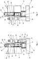
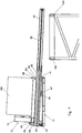
- Lever 130 is then pushed in direction A, so that the PLC 93 executes the "Tilt down” stage of the first sequence, and then upon receiving the signal from switch means 87 the “Rail out” stage of the first sequence, until the switch means 85 indicates that the rails 24 are fully extended. In this position, as illustrated in figure 7 , the extended rails which are tilted downwardly, are supported above the front and rear beams 142, 144 of the racking system.
- the forks of the fork lift truck and the mechanism 10 mounted thereon are then lowered, until the rails 24 come into engagement with the rear beam 144 of the racking system. Continued lowering of the forks of the lift truck will then tilt the rails 24 upwardly, until the rails 24 also engage the front rail 142, as illustrated in figure 8 .
- the rails 24 are level, operator stops the forks of the fork lift truck and the level sensor 92 produces a signal to inform the PLC 93 that the mechanism is ready to proceed to the next stage of the first sequence.
- Lever 130 is then pushed forwards in direction A and the PLC 93 then executes the "Carriage out” stage of the first sequence, until the carriage 50 reaches the limit of its movement away from the hinged ends of rails 24 and the upright portions of forks 82 abut against the front face of the pallet 150.
- Lever 130 is then pulled back in direction B and the PLC 93 executes the "Lift down" stage of the second sequence, lowering the pallet 150 on to the beams 142, 144, and clear of the pallet.
- the PLC 93 executes the "Tilt up” stage of the first sequence and when limit switch 86 indicates that the rams 45 are at the limit if their extension when the rails 24 will be clear of the beams 142, 144, the PLC 93 will execute the "Rail in” stage of the first sequence.
- the PLC 93 may be programmed with maximum periods for carrying out the various stages of the first and second sequences. If a stage is timed out or the PLC 93 detects some other malfunction of an operation, for example if the level sensor 92 indicates that the mechanism with the rails extended, has been lowered below the appropriate level, so that the rails engage only the front beam 142 of the racking system, it will stop and sound an alarm. If the alarm sounds, or if the operator observes a problem during any stage of the first and second sequence, movement of lever 130 to the central neutral position for a time out period, will reset the PLC 93 and cause it to reverse any incomplete stage of the first and second sequence.
- the operation of the mechanism 10 as described above, is with respect to a pallet with top and bottom decks, which requires the rails 24 to lie outside the vertical projection of the pallet.
- the pallets which do not have a bottom deck for example a standard European Pallet, where the rails 24 may engage the beams 142, 144 of the racking system below the upper deck of the pallet, the pallet may overlie the rails 24.
- the telescopic rails and components of the carriage may be located outside the vertical projection of the pallet. This may be achieved by designing the attachment for a specific maximum width of pallet, for example a standard pallet width. Alternatively, the lateral separation of the telescopic rails and width of the carriage may be adjustable.
- mechanism 10 is particularly suitable for transferring pallets, it may be used with other loads, for example boxes or bins which have raised bases permitting access for the forks 82 of the mechanism 10.
- the mechanism of the present invention has been described as an attachment 10 is designed to be mounted on the lifting forks of the lift truck, the mechanism may alternatively be designed as an integrated part of the lift truck to replace the forks of the lift mechanism of the lift truck or may form the permanent lifting device of the lift truck.
- a dedicated control system may also be integrated with the control systems of the lift truck, providing for example separate control means for the mechanism and other systems of the lift truck.
- the telescopic rail assembly may alternatively be mounted to a sub-frame for rotation in a horizontal plane so that the telescopic rails 24 could be rotated to transfer loads to either side or to the front of the lift truck.
- a load may be transferred from racking on one side of the lift truck to racking on the other side of the lift truck or in front of the lift truck, without lowering the load to the ground.
Landscapes
- Engineering & Computer Science (AREA)
- Transportation (AREA)
- Structural Engineering (AREA)
- Mechanical Engineering (AREA)
- Civil Engineering (AREA)
- Life Sciences & Earth Sciences (AREA)
- Geology (AREA)
- Forklifts And Lifting Vehicles (AREA)
Claims (11)
- Mechanismus (10) für das Transferieren von Lasten zwischen einem Regalsystem und einem Hubwagen und dazu ausgelegt, an einem Hebemechanismus des Hubwagens befestigt zu werden, wobei der Mechanismus (10) einen Rahmen (12) umfasst, der dazu ausgelegt ist, an dem Hebemechanismus des Hubwagens montiert zu werden, und gekennzeichnet ist durch ein Paar teleskopischer Schienen (24), die an einem Ende des Rahmens (12) montiert sind, wobei sich die teleskopischen Schienen (24) parallel zueinander erstrecken, die teleskopischen Schienen (24) im Gebrauch seitlich des Hebemechanismus des Hubwagens zwischen eingezogenen und ausgefahrenen Positionen ausfahrbar sind, Mittel (40) zum Bewegen der teleskopischen Schienen (24), einen Wagen (50), der an den teleskopischen Schienen (24) zur Bewegung dort entlang montiert ist, wenn sich die teleskopischen Schienen (24) in ihren ausgefahrenen Positionen befinden und die freien Enden der teleskopischen Schienen (24) im Gebrauch von dem Regalsystem gestützt werden, wobei an dem Wagen (50) ein Hebemechanismus (70) montiert ist, durch den eine Last relativ zu dem Wagen (50) angehoben und abgesenkt werden kann.
- Mechanismus (10) nach Anspruch 1, dadurch gekennzeichnet, dass die teleskopischen Schienen (24), der Wagen (50) und der Hebemechanismus (70) hydraulisch, pneumatisch, elektrisch und/oder mechanisch angetrieben werden.
- Mechanismus (10) nach Anspruch 1 oder Anspruch 2, dadurch gekennzeichnet, dass die teleskopischen Schienen (24), der Wagen (50) und der Hebemechanismus (70) im Gebrauch von einem Nebenantrieb des Antriebssystems des Hubwagens angetrieben werden.
- Mechanismus (10) nach einem der vorangehenden Ansprüche, dadurch gekennzeichnet, dass ein Steuerungssystem (100) mit Mitteln zur Sequenzierung der verschiedenen Operationen des Mechanismus (10) ausgestattet ist.
- Mechanismus (10) nach Anspruch 4, dadurch gekennzeichnet, dass das Steuerungssystem (100) Verriegelungsmittel beinhaltet, um im Gebrauch eine Bewegung des Wagens (50) aus seiner zurückgezogenen Position zu verhindern, bis die teleskopischen Schienen (24) in ihrer ausgefahrenen Position sind und im Gebrauch an ihren freien Enden abgestützt sind.
- Mechanismus (10) nach Anspruch 4 oder Anspruch 5, dadurch gekennzeichnet, dass das Steuerungssystem (100) Mittel zum Zurücksetzen des Systems beinhaltet, falls bei einer Operation des Mechanismus (10) eine Fehlfunktion auftritt.
- Mechanismus (10) nach einem der vorangehenden Ansprüche, dadurch gekennzeichnet, dass der Rahmen (12) dazu ausgelegt ist, im Gebrauch an Gabeln des Hebemechanismus des Hubwagens angebracht zu werden, wobei der Rahmen (12) von jeder Seite an den Gabeln montiert werden kann, sodass die teleskopischen Schienen (24) im Gebrauch zu jeder Seite des Hubwagens ausfahrbar sein können.
- Mechanismus (10) nach einem der Ansprüche 1 bis 6, dadurch gekennzeichnet, dass die teleskopischen Schienen (24) so an dem Rahmen (12) montiert sind, dass sie um eine vertikale Achse drehbar sind, wobei die teleskopischen Schienen (24) im Gebrauch so gedreht werden können, dass sie sich zu jeder Seite des Hubwagens erstrecken.
- Mechanismus (10) nach einem der vorangehenden Ansprüche, dadurch gekennzeichnet, dass die teleskopischen Schienen (24) über einer horizontalen Querachse durch Scharniere (22) an einem Ende des Rahmens (12) montiert sind; wobei die teleskopischen Schienen (24) frei sind, sich relativ zu dem Rahmen (12) zwischen einer abgesenkten Position, in der die teleskopischen Schienen (24) von den mit Scharnieren versehenen Enden zu den freien Enden in Richtung des Rahmens (12) abwärts geneigt sind, und einer angehobenen Position, in der die teleskopischen Schienen von den mit Scharnieren versehenen Enden zu den freien Enden von dem Rahmen (12) weg aufwärts geneigt sind, zu drehen; wobei dann, wenn die teleskopischen Schienen (24) in ihrer nach unten geneigten Position ausgefahren sind, die teleskopischen Schienen (24) im Gebrauch zuerst in einen Eingriff mit einer Stützfläche (142, 144) gebracht werden können, angrenzend an ihre Enden durch Absenken des Mechanismus (10) an zwei oder mehr Punkten in einen Eingriff mit der Stützfläche (142, 244) gebracht werden können.
- Mechanismus (10) nach Anspruch 9, dadurch gekennzeichnet, dass Mittel (45) zum Bewegen der teleskopischen Schienen von ihrer abwärts geneigten in ihre aufwärts geneigte Position vorgesehen sind, wobei noch immer eine freie Bewegung der teleskopischen Schienen (24) von ihrer abwärts geneigten Position aufwärts gestattet ist.
- Mechanismus (10) nach Anspruch 9, in dem ein Niveauschalter (92) durch Bewegung der teleskopischen Schienen (24) um die Scharniere (22) betätigt wird, um im Gebrauch einen Anhaltspunkt dafür bereitzustellen, wann die teleskopischen Schienen (24) parallel zu der Stützfläche (142, 144) verlaufen und vollständig von der Stützfläche abgestützt sind.
Applications Claiming Priority (2)
| Application Number | Priority Date | Filing Date | Title |
|---|---|---|---|
| GB201504172A GB201504172D0 (en) | 2015-03-12 | 2015-03-12 | Fork lift trucks |
| PCT/GB2016/000050 WO2016142641A1 (en) | 2015-03-12 | 2016-03-14 | Load transfer mechanism |
Publications (2)
| Publication Number | Publication Date |
|---|---|
| EP3268301A1 EP3268301A1 (de) | 2018-01-17 |
| EP3268301B1 true EP3268301B1 (de) | 2019-08-07 |
Family
ID=53015999
Family Applications (1)
| Application Number | Title | Priority Date | Filing Date |
|---|---|---|---|
| EP16712973.3A Active EP3268301B1 (de) | 2015-03-12 | 2016-03-14 | Mechanismus für den transfer einer last |
Country Status (4)
| Country | Link |
|---|---|
| US (1) | US10815055B2 (de) |
| EP (1) | EP3268301B1 (de) |
| GB (1) | GB201504172D0 (de) |
| WO (1) | WO2016142641A1 (de) |
Cited By (1)
| Publication number | Priority date | Publication date | Assignee | Title |
|---|---|---|---|---|
| EP4342823A4 (de) * | 2021-10-15 | 2025-05-07 | Beijing Geekplus Technology Co., Ltd. | Behälteraufnahme- und -förderanlage, be- und entladevorrichtung, kommissioniersystem, logistiksortiersystem und behälteraufnahme- und -förderverfahren |
Families Citing this family (21)
| Publication number | Priority date | Publication date | Assignee | Title |
|---|---|---|---|---|
| US11465840B2 (en) * | 2017-11-14 | 2022-10-11 | Hai Robotics Co., Ltd. | Handling robot |
| US12103771B2 (en) * | 2017-11-14 | 2024-10-01 | Hai Robotics Co., Ltd. | Handling robot |
| CA3084526C (en) * | 2017-11-14 | 2024-02-20 | Hai Robotics Co., Ltd. | Handling robot and method for retrieving inventory item based on handling robot |
| US12330870B2 (en) * | 2017-11-14 | 2025-06-17 | Hai Robotics Co., Ltd. | Handling robot |
| US12006143B2 (en) * | 2017-11-14 | 2024-06-11 | Hai Robotics Co., Ltd. | Handling robot |
| TWI743389B (zh) * | 2018-08-30 | 2021-10-21 | 張志峰 | 運輸設備 |
| CN111345635B (zh) * | 2018-12-20 | 2023-05-02 | 北京京东乾石科技有限公司 | 运动装置 |
| DE102019100420A1 (de) * | 2019-01-09 | 2020-07-09 | Nedcon B.V. | Warenlager für die Einzelplatzlagerung von Stückgütern |
| US11597598B2 (en) | 2019-02-01 | 2023-03-07 | Hai Robotics Co., Ltd. | Handling robot |
| US11542135B2 (en) | 2019-02-01 | 2023-01-03 | Hai Robotics Co., Ltd. | Handling robot |
| US11807451B2 (en) * | 2019-09-17 | 2023-11-07 | Hai Robotics Co., Ltd. | Fork and carrying robot |
| CN111825025B (zh) * | 2020-08-05 | 2022-03-01 | 杭州职业技术学院 | 一种防倾倒式物流叉车 |
| DE102020127921A1 (de) * | 2020-10-23 | 2022-04-28 | Dambach Lagersysteme Gmbh & Co. Kg | Regalbediengerät und Verfahren zum Auslagern eines Objektes aus einem Regalfach eines Regallagers |
| CN112830277A (zh) * | 2020-12-02 | 2021-05-25 | 江苏格莱富智能装备有限公司 | 货柜车自动检测装车系统 |
| CN114684516B (zh) * | 2020-12-31 | 2023-05-02 | 深圳市海柔创新科技有限公司 | 货叉组件的控制方法、货叉组件及机器人 |
| CN113233119B (zh) * | 2021-05-31 | 2022-09-23 | 台州市握奇自动化设备有限公司 | 一种自动化仓库 |
| US20230011746A1 (en) * | 2021-07-06 | 2023-01-12 | Intelligrated Headquarters, Llc | Modular autonomous vehicle |
| USD1077008S1 (en) * | 2021-12-17 | 2025-05-27 | Ocado Innovation Limited | Load handling device |
| USD1077007S1 (en) * | 2022-01-19 | 2025-05-27 | Ocado Innovation Limited | Load handling device |
| US20230406639A1 (en) * | 2022-04-29 | 2023-12-21 | Kenton Brett | System and method for local tube transport |
| CN114633983B (zh) * | 2022-05-19 | 2022-07-29 | 佛山井松智能科技有限公司 | 一种立体化仓库用提升机 |
Family Cites Families (6)
| Publication number | Priority date | Publication date | Assignee | Title |
|---|---|---|---|---|
| NL133258C (de) * | ||||
| US3549025A (en) * | 1969-10-09 | 1970-12-22 | Clark Equipment Co | Side loader device |
| US4058270A (en) * | 1976-08-12 | 1977-11-15 | Interlake, Inc. | Strap dispensing system |
| US5011363A (en) * | 1989-12-05 | 1991-04-30 | Crown Equipment Corporation | Extend and retract control for fork lifts |
| US6179541B1 (en) * | 1999-10-25 | 2001-01-30 | Sylvain Rioux | Transfer device for lumber packs and other loads |
| GB0024648D0 (en) * | 2000-10-07 | 2000-11-22 | Bae Systems Plc | A method and apparatus for assembling an aircraft wheel or brake component on an axle of an undercarriage |
-
2015
- 2015-03-12 GB GB201504172A patent/GB201504172D0/en not_active Ceased
-
2016
- 2016-03-14 US US15/557,550 patent/US10815055B2/en active Active
- 2016-03-14 EP EP16712973.3A patent/EP3268301B1/de active Active
- 2016-03-14 WO PCT/GB2016/000050 patent/WO2016142641A1/en not_active Ceased
Non-Patent Citations (1)
| Title |
|---|
| None * |
Cited By (1)
| Publication number | Priority date | Publication date | Assignee | Title |
|---|---|---|---|---|
| EP4342823A4 (de) * | 2021-10-15 | 2025-05-07 | Beijing Geekplus Technology Co., Ltd. | Behälteraufnahme- und -förderanlage, be- und entladevorrichtung, kommissioniersystem, logistiksortiersystem und behälteraufnahme- und -förderverfahren |
Also Published As
| Publication number | Publication date |
|---|---|
| US10815055B2 (en) | 2020-10-27 |
| EP3268301A1 (de) | 2018-01-17 |
| US20180050868A1 (en) | 2018-02-22 |
| GB201504172D0 (en) | 2015-04-29 |
| WO2016142641A1 (en) | 2016-09-15 |
Similar Documents
| Publication | Publication Date | Title |
|---|---|---|
| EP3268301B1 (de) | Mechanismus für den transfer einer last | |
| US5716184A (en) | Loader for stacking packages in shipping containers | |
| US9221501B2 (en) | Platform system for a cargo compartment of a truck, lorry or trailer | |
| EP3016863B1 (de) | Mehrstöckiger frachtbehälter | |
| WO2018150153A9 (en) | Lifting shipping containers | |
| US11117790B2 (en) | Industrial truck comprising a thrust device | |
| JP2020531382A (ja) | 横方向に動作する積載物取扱装置 | |
| US20230192425A1 (en) | Apparatus and method for unloading and loading a transport unit | |
| KR20200061520A (ko) | 길이조절 암을 구비한 개량형 셔틀 구조 | |
| US6648581B2 (en) | Order picker truck | |
| CN110803436B (zh) | 一种水平开合的货物堆叠校正系统 | |
| EP1775246B1 (de) | Modulare Hebevorrichtung | |
| CN114620400A (zh) | 一种智能码垛系统 | |
| KR102078227B1 (ko) | 적재함 교체가 가능한 모듈형 셔틀 구조 | |
| KR102078228B1 (ko) | 적재함 리프팅이 가능한 모듈형 셔틀 구조 | |
| JP5821823B2 (ja) | 物品収納設備 | |
| CA2097575A1 (en) | Facility for the manoeuvreing of pallets in gantry cranes | |
| CN107650757B (zh) | 一种便捷上货、卸货的agv小车 | |
| DE29620342U1 (de) | Satellitenfahrzeug | |
| JP5280138B2 (ja) | 昇降載置台付台車 | |
| AU2015100606A4 (en) | A lifting unit for a loading dock | |
| US20240224876A9 (en) | Agricultural wagon | |
| US5330306A (en) | Pallet handling platten unit | |
| CA2514362A1 (en) | Platform for forklift | |
| JPH07112805A (ja) | マスト |
Legal Events
| Date | Code | Title | Description |
|---|---|---|---|
| STAA | Information on the status of an ep patent application or granted ep patent |
Free format text: STATUS: THE INTERNATIONAL PUBLICATION HAS BEEN MADE |
|
| PUAI | Public reference made under article 153(3) epc to a published international application that has entered the european phase |
Free format text: ORIGINAL CODE: 0009012 |
|
| STAA | Information on the status of an ep patent application or granted ep patent |
Free format text: STATUS: REQUEST FOR EXAMINATION WAS MADE |
|
| 17P | Request for examination filed |
Effective date: 20171004 |
|
| AK | Designated contracting states |
Kind code of ref document: A1 Designated state(s): AL AT BE BG CH CY CZ DE DK EE ES FI FR GB GR HR HU IE IS IT LI LT LU LV MC MK MT NL NO PL PT RO RS SE SI SK SM TR |
|
| AX | Request for extension of the european patent |
Extension state: BA ME |
|
| DAV | Request for validation of the european patent (deleted) | ||
| DAX | Request for extension of the european patent (deleted) | ||
| GRAP | Despatch of communication of intention to grant a patent |
Free format text: ORIGINAL CODE: EPIDOSNIGR1 |
|
| STAA | Information on the status of an ep patent application or granted ep patent |
Free format text: STATUS: GRANT OF PATENT IS INTENDED |
|
| RIC1 | Information provided on ipc code assigned before grant |
Ipc: B66F 9/14 20060101AFI20190130BHEP Ipc: B65G 1/04 20060101ALI20190130BHEP |
|
| INTG | Intention to grant announced |
Effective date: 20190222 |
|
| GRAS | Grant fee paid |
Free format text: ORIGINAL CODE: EPIDOSNIGR3 |
|
| GRAA | (expected) grant |
Free format text: ORIGINAL CODE: 0009210 |
|
| STAA | Information on the status of an ep patent application or granted ep patent |
Free format text: STATUS: THE PATENT HAS BEEN GRANTED |
|
| AK | Designated contracting states |
Kind code of ref document: B1 Designated state(s): AL AT BE BG CH CY CZ DE DK EE ES FI FR GB GR HR HU IE IS IT LI LT LU LV MC MK MT NL NO PL PT RO RS SE SI SK SM TR |
|
| REG | Reference to a national code |
Ref country code: GB Ref legal event code: FG4D |
|
| REG | Reference to a national code |
Ref country code: CH Ref legal event code: EP Ref country code: AT Ref legal event code: REF Ref document number: 1163558 Country of ref document: AT Kind code of ref document: T Effective date: 20190815 |
|
| REG | Reference to a national code |
Ref country code: IE Ref legal event code: FG4D |
|
| REG | Reference to a national code |
Ref country code: DE Ref legal event code: R096 Ref document number: 602016018092 Country of ref document: DE |
|
| REG | Reference to a national code |
Ref country code: NL Ref legal event code: MP Effective date: 20190807 |
|
| REG | Reference to a national code |
Ref country code: LT Ref legal event code: MG4D |
|
| PG25 | Lapsed in a contracting state [announced via postgrant information from national office to epo] |
Ref country code: HR Free format text: LAPSE BECAUSE OF FAILURE TO SUBMIT A TRANSLATION OF THE DESCRIPTION OR TO PAY THE FEE WITHIN THE PRESCRIBED TIME-LIMIT Effective date: 20190807 Ref country code: SE Free format text: LAPSE BECAUSE OF FAILURE TO SUBMIT A TRANSLATION OF THE DESCRIPTION OR TO PAY THE FEE WITHIN THE PRESCRIBED TIME-LIMIT Effective date: 20190807 Ref country code: NO Free format text: LAPSE BECAUSE OF FAILURE TO SUBMIT A TRANSLATION OF THE DESCRIPTION OR TO PAY THE FEE WITHIN THE PRESCRIBED TIME-LIMIT Effective date: 20191107 Ref country code: FI Free format text: LAPSE BECAUSE OF FAILURE TO SUBMIT A TRANSLATION OF THE DESCRIPTION OR TO PAY THE FEE WITHIN THE PRESCRIBED TIME-LIMIT Effective date: 20190807 Ref country code: PT Free format text: LAPSE BECAUSE OF FAILURE TO SUBMIT A TRANSLATION OF THE DESCRIPTION OR TO PAY THE FEE WITHIN THE PRESCRIBED TIME-LIMIT Effective date: 20191209 Ref country code: BG Free format text: LAPSE BECAUSE OF FAILURE TO SUBMIT A TRANSLATION OF THE DESCRIPTION OR TO PAY THE FEE WITHIN THE PRESCRIBED TIME-LIMIT Effective date: 20191107 Ref country code: LT Free format text: LAPSE BECAUSE OF FAILURE TO SUBMIT A TRANSLATION OF THE DESCRIPTION OR TO PAY THE FEE WITHIN THE PRESCRIBED TIME-LIMIT Effective date: 20190807 Ref country code: NL Free format text: LAPSE BECAUSE OF FAILURE TO SUBMIT A TRANSLATION OF THE DESCRIPTION OR TO PAY THE FEE WITHIN THE PRESCRIBED TIME-LIMIT Effective date: 20190807 |
|
| REG | Reference to a national code |
Ref country code: AT Ref legal event code: MK05 Ref document number: 1163558 Country of ref document: AT Kind code of ref document: T Effective date: 20190807 |
|
| PG25 | Lapsed in a contracting state [announced via postgrant information from national office to epo] |
Ref country code: IS Free format text: LAPSE BECAUSE OF FAILURE TO SUBMIT A TRANSLATION OF THE DESCRIPTION OR TO PAY THE FEE WITHIN THE PRESCRIBED TIME-LIMIT Effective date: 20191207 Ref country code: RS Free format text: LAPSE BECAUSE OF FAILURE TO SUBMIT A TRANSLATION OF THE DESCRIPTION OR TO PAY THE FEE WITHIN THE PRESCRIBED TIME-LIMIT Effective date: 20190807 Ref country code: LV Free format text: LAPSE BECAUSE OF FAILURE TO SUBMIT A TRANSLATION OF THE DESCRIPTION OR TO PAY THE FEE WITHIN THE PRESCRIBED TIME-LIMIT Effective date: 20190807 Ref country code: AL Free format text: LAPSE BECAUSE OF FAILURE TO SUBMIT A TRANSLATION OF THE DESCRIPTION OR TO PAY THE FEE WITHIN THE PRESCRIBED TIME-LIMIT Effective date: 20190807 Ref country code: ES Free format text: LAPSE BECAUSE OF FAILURE TO SUBMIT A TRANSLATION OF THE DESCRIPTION OR TO PAY THE FEE WITHIN THE PRESCRIBED TIME-LIMIT Effective date: 20190807 Ref country code: GR Free format text: LAPSE BECAUSE OF FAILURE TO SUBMIT A TRANSLATION OF THE DESCRIPTION OR TO PAY THE FEE WITHIN THE PRESCRIBED TIME-LIMIT Effective date: 20191108 |
|
| PG25 | Lapsed in a contracting state [announced via postgrant information from national office to epo] |
Ref country code: TR Free format text: LAPSE BECAUSE OF FAILURE TO SUBMIT A TRANSLATION OF THE DESCRIPTION OR TO PAY THE FEE WITHIN THE PRESCRIBED TIME-LIMIT Effective date: 20190807 |
|
| PG25 | Lapsed in a contracting state [announced via postgrant information from national office to epo] |
Ref country code: AT Free format text: LAPSE BECAUSE OF FAILURE TO SUBMIT A TRANSLATION OF THE DESCRIPTION OR TO PAY THE FEE WITHIN THE PRESCRIBED TIME-LIMIT Effective date: 20190807 Ref country code: DK Free format text: LAPSE BECAUSE OF FAILURE TO SUBMIT A TRANSLATION OF THE DESCRIPTION OR TO PAY THE FEE WITHIN THE PRESCRIBED TIME-LIMIT Effective date: 20190807 Ref country code: PL Free format text: LAPSE BECAUSE OF FAILURE TO SUBMIT A TRANSLATION OF THE DESCRIPTION OR TO PAY THE FEE WITHIN THE PRESCRIBED TIME-LIMIT Effective date: 20190807 Ref country code: RO Free format text: LAPSE BECAUSE OF FAILURE TO SUBMIT A TRANSLATION OF THE DESCRIPTION OR TO PAY THE FEE WITHIN THE PRESCRIBED TIME-LIMIT Effective date: 20190807 Ref country code: EE Free format text: LAPSE BECAUSE OF FAILURE TO SUBMIT A TRANSLATION OF THE DESCRIPTION OR TO PAY THE FEE WITHIN THE PRESCRIBED TIME-LIMIT Effective date: 20190807 Ref country code: IT Free format text: LAPSE BECAUSE OF FAILURE TO SUBMIT A TRANSLATION OF THE DESCRIPTION OR TO PAY THE FEE WITHIN THE PRESCRIBED TIME-LIMIT Effective date: 20190807 |
|
| PG25 | Lapsed in a contracting state [announced via postgrant information from national office to epo] |
Ref country code: SM Free format text: LAPSE BECAUSE OF FAILURE TO SUBMIT A TRANSLATION OF THE DESCRIPTION OR TO PAY THE FEE WITHIN THE PRESCRIBED TIME-LIMIT Effective date: 20190807 Ref country code: IS Free format text: LAPSE BECAUSE OF FAILURE TO SUBMIT A TRANSLATION OF THE DESCRIPTION OR TO PAY THE FEE WITHIN THE PRESCRIBED TIME-LIMIT Effective date: 20200224 Ref country code: CZ Free format text: LAPSE BECAUSE OF FAILURE TO SUBMIT A TRANSLATION OF THE DESCRIPTION OR TO PAY THE FEE WITHIN THE PRESCRIBED TIME-LIMIT Effective date: 20190807 Ref country code: SK Free format text: LAPSE BECAUSE OF FAILURE TO SUBMIT A TRANSLATION OF THE DESCRIPTION OR TO PAY THE FEE WITHIN THE PRESCRIBED TIME-LIMIT Effective date: 20190807 |
|
| REG | Reference to a national code |
Ref country code: DE Ref legal event code: R097 Ref document number: 602016018092 Country of ref document: DE |
|
| PLBE | No opposition filed within time limit |
Free format text: ORIGINAL CODE: 0009261 |
|
| STAA | Information on the status of an ep patent application or granted ep patent |
Free format text: STATUS: NO OPPOSITION FILED WITHIN TIME LIMIT |
|
| PG2D | Information on lapse in contracting state deleted |
Ref country code: IS |
|
| 26N | No opposition filed |
Effective date: 20200603 |
|
| PG25 | Lapsed in a contracting state [announced via postgrant information from national office to epo] |
Ref country code: SI Free format text: LAPSE BECAUSE OF FAILURE TO SUBMIT A TRANSLATION OF THE DESCRIPTION OR TO PAY THE FEE WITHIN THE PRESCRIBED TIME-LIMIT Effective date: 20190807 |
|
| REG | Reference to a national code |
Ref country code: DE Ref legal event code: R119 Ref document number: 602016018092 Country of ref document: DE |
|
| PG25 | Lapsed in a contracting state [announced via postgrant information from national office to epo] |
Ref country code: MC Free format text: LAPSE BECAUSE OF FAILURE TO SUBMIT A TRANSLATION OF THE DESCRIPTION OR TO PAY THE FEE WITHIN THE PRESCRIBED TIME-LIMIT Effective date: 20190807 |
|
| REG | Reference to a national code |
Ref country code: CH Ref legal event code: PL |
|
| REG | Reference to a national code |
Ref country code: BE Ref legal event code: MM Effective date: 20200331 |
|
| PG25 | Lapsed in a contracting state [announced via postgrant information from national office to epo] |
Ref country code: LU Free format text: LAPSE BECAUSE OF NON-PAYMENT OF DUE FEES Effective date: 20200314 |
|
| PG25 | Lapsed in a contracting state [announced via postgrant information from national office to epo] |
Ref country code: DE Free format text: LAPSE BECAUSE OF NON-PAYMENT OF DUE FEES Effective date: 20201001 Ref country code: LI Free format text: LAPSE BECAUSE OF NON-PAYMENT OF DUE FEES Effective date: 20200331 Ref country code: CH Free format text: LAPSE BECAUSE OF NON-PAYMENT OF DUE FEES Effective date: 20200331 Ref country code: FR Free format text: LAPSE BECAUSE OF NON-PAYMENT OF DUE FEES Effective date: 20200331 |
|
| PG25 | Lapsed in a contracting state [announced via postgrant information from national office to epo] |
Ref country code: BE Free format text: LAPSE BECAUSE OF NON-PAYMENT OF DUE FEES Effective date: 20200331 |
|
| PG25 | Lapsed in a contracting state [announced via postgrant information from national office to epo] |
Ref country code: MT Free format text: LAPSE BECAUSE OF FAILURE TO SUBMIT A TRANSLATION OF THE DESCRIPTION OR TO PAY THE FEE WITHIN THE PRESCRIBED TIME-LIMIT Effective date: 20190807 Ref country code: CY Free format text: LAPSE BECAUSE OF FAILURE TO SUBMIT A TRANSLATION OF THE DESCRIPTION OR TO PAY THE FEE WITHIN THE PRESCRIBED TIME-LIMIT Effective date: 20190807 |
|
| PG25 | Lapsed in a contracting state [announced via postgrant information from national office to epo] |
Ref country code: MK Free format text: LAPSE BECAUSE OF FAILURE TO SUBMIT A TRANSLATION OF THE DESCRIPTION OR TO PAY THE FEE WITHIN THE PRESCRIBED TIME-LIMIT Effective date: 20190807 |
|
| PGFP | Annual fee paid to national office [announced via postgrant information from national office to epo] |
Ref country code: GB Payment date: 20260220 Year of fee payment: 11 |
|
| PGFP | Annual fee paid to national office [announced via postgrant information from national office to epo] |
Ref country code: IE Payment date: 20260220 Year of fee payment: 11 |