EP3265862B1 - Farbkorrekturkollimation von licht aus einer winkelfarblichtpositionsquelle - Google Patents
Farbkorrekturkollimation von licht aus einer winkelfarblichtpositionsquelle Download PDFInfo
- Publication number
- EP3265862B1 EP3265862B1 EP16701634.4A EP16701634A EP3265862B1 EP 3265862 B1 EP3265862 B1 EP 3265862B1 EP 16701634 A EP16701634 A EP 16701634A EP 3265862 B1 EP3265862 B1 EP 3265862B1
- Authority
- EP
- European Patent Office
- Prior art keywords
- light
- spreading elements
- light spreading
- light source
- image
- Prior art date
- Legal status (The legal status is an assumption and is not a legal conclusion. Google has not performed a legal analysis and makes no representation as to the accuracy of the status listed.)
- Active
Links
- 238000003384 imaging method Methods 0.000 claims description 49
- 230000003287 optical effect Effects 0.000 claims description 46
- 238000000034 method Methods 0.000 claims description 8
- 239000003086 colorant Substances 0.000 description 13
- 230000001419 dependent effect Effects 0.000 description 6
- 238000005286 illumination Methods 0.000 description 6
- 239000000463 material Substances 0.000 description 3
- -1 poly(methyl methacrylate) Polymers 0.000 description 3
- 238000009792 diffusion process Methods 0.000 description 2
- 239000004033 plastic Substances 0.000 description 2
- 229920003023 plastic Polymers 0.000 description 2
- 238000000926 separation method Methods 0.000 description 2
- 229920000089 Cyclic olefin copolymer Polymers 0.000 description 1
- 239000004713 Cyclic olefin copolymer Substances 0.000 description 1
- 150000001252 acrylic acid derivatives Chemical class 0.000 description 1
- 230000003213 activating effect Effects 0.000 description 1
- 229910052782 aluminium Inorganic materials 0.000 description 1
- XAGFODPZIPBFFR-UHFFFAOYSA-N aluminium Chemical compound [Al] XAGFODPZIPBFFR-UHFFFAOYSA-N 0.000 description 1
- 230000005540 biological transmission Effects 0.000 description 1
- 239000011521 glass Substances 0.000 description 1
- 229910052751 metal Inorganic materials 0.000 description 1
- 239000002184 metal Substances 0.000 description 1
- 150000002739 metals Chemical class 0.000 description 1
- 238000012986 modification Methods 0.000 description 1
- 230000004048 modification Effects 0.000 description 1
- 229920003229 poly(methyl methacrylate) Polymers 0.000 description 1
- 229920000515 polycarbonate Polymers 0.000 description 1
- 239000004417 polycarbonate Substances 0.000 description 1
- 239000004926 polymethyl methacrylate Substances 0.000 description 1
- 230000001902 propagating effect Effects 0.000 description 1
- 229920005573 silicon-containing polymer Polymers 0.000 description 1
Images


Classifications
-
- G—PHYSICS
- G02—OPTICS
- G02B—OPTICAL ELEMENTS, SYSTEMS OR APPARATUS
- G02B19/00—Condensers, e.g. light collectors or similar non-imaging optics
- G02B19/0004—Condensers, e.g. light collectors or similar non-imaging optics characterised by the optical means employed
- G02B19/0028—Condensers, e.g. light collectors or similar non-imaging optics characterised by the optical means employed refractive and reflective surfaces, e.g. non-imaging catadioptric systems
-
- F—MECHANICAL ENGINEERING; LIGHTING; HEATING; WEAPONS; BLASTING
- F21—LIGHTING
- F21K—NON-ELECTRIC LIGHT SOURCES USING LUMINESCENCE; LIGHT SOURCES USING ELECTROCHEMILUMINESCENCE; LIGHT SOURCES USING CHARGES OF COMBUSTIBLE MATERIAL; LIGHT SOURCES USING SEMICONDUCTOR DEVICES AS LIGHT-GENERATING ELEMENTS; LIGHT SOURCES NOT OTHERWISE PROVIDED FOR
- F21K9/00—Light sources using semiconductor devices as light-generating elements, e.g. using light-emitting diodes [LED] or lasers
- F21K9/60—Optical arrangements integrated in the light source, e.g. for improving the colour rendering index or the light extraction
- F21K9/62—Optical arrangements integrated in the light source, e.g. for improving the colour rendering index or the light extraction using mixing chambers, e.g. housings with reflective walls
-
- G—PHYSICS
- G02—OPTICS
- G02B—OPTICAL ELEMENTS, SYSTEMS OR APPARATUS
- G02B19/00—Condensers, e.g. light collectors or similar non-imaging optics
- G02B19/0033—Condensers, e.g. light collectors or similar non-imaging optics characterised by the use
- G02B19/0047—Condensers, e.g. light collectors or similar non-imaging optics characterised by the use for use with a light source
- G02B19/0061—Condensers, e.g. light collectors or similar non-imaging optics characterised by the use for use with a light source the light source comprising a LED
-
- F—MECHANICAL ENGINEERING; LIGHTING; HEATING; WEAPONS; BLASTING
- F21—LIGHTING
- F21Y—INDEXING SCHEME ASSOCIATED WITH SUBCLASSES F21K, F21L, F21S and F21V, RELATING TO THE FORM OR THE KIND OF THE LIGHT SOURCES OR OF THE COLOUR OF THE LIGHT EMITTED
- F21Y2115/00—Light-generating elements of semiconductor light sources
- F21Y2115/10—Light-emitting diodes [LED]
Definitions
- the present invention relates to a collimator for a color over position light source, a lighting device comprising a collimator, and an associated method.
- WO 2013/035036 A1 discloses collimators having rotationally symmetric surface segments designed to correct so-called "color over angle” (CoA) variation. In short, CoA variation results from the color of the emitted light being dependent on the angle of emission.
- CoA color over angle
- Color over position refers to situations where the color of the emitted light depends on the position of emission on the light source. It is possible to use collimators for reducing CoP variation, but different technical requirements have to be met compared with the case of CoA variation.
- the application US 2009/219716 A1 discloses a lighting device comprising a collimator for a color over position light source.
- a lighting device comprising a collimator and a CoP light source as defined in claim 1. Additional embodiments are defined in the dependent claims.
- the collimator comprises: a focal point (F), an optical axis containing the focal point (F), an imaging element arranged around or on the optical axis, and several light spreading elements arranged around the optical axis to receive at least one image from the imaging element.
- the light spreading elements have different light beam widening characteristics, and the light beam widening characteristics of each light spreading element of said light spreading elements depend on the position of the light spreading elements relative to the focal point (F).
- the light spreading elements are adapted to spread light striking the light spreading elements in a first plane that includes the optical axis.
- CoP light source a light source that has CoP variation. That is to say, the color of the light emitted by the light source depends on the position on the light source from which the light is emitted.
- Providing the collimator with position dependent light spreading elements on which an imaging element forms at least one image improves the mixing of light having different colors and may thus reduce undesirable color variations in the far field light from a CoP light source.
- the imaging element is configured for one dimensional imaging. According to another embodiment, the imaging element is configured for two dimensional imaging. Depending on the technical requirements of the intended application or for cost reasons, one type of imaging element may be preferred over the other.
- each light spreading element depends on an optical path length measured from the focal point to the light spreading element.
- the light beam widening characteristics of each light spreading element depend on the orthogonal distance from the optical axis to the light spreading element. Collimators often have such shapes that these types of position dependence results in a good mixing of light of different colors in the far field.
- the light spreading elements are adapted to spread light striking the light spreading elements in both the first plane and a second plane which is orthogonal to the first plane and which has a normal that is orthogonal to the optical axis. Spreading the light in two planes, rather than in only one plane, may improve the mixing of light of different colors in the far field.
- the light spreading elements are microlenses or facets. In some examples, the light spreading elements are diffusive elements. These types of light spreading elements are easily manufactured to have the light beam widening characteristics required for a particular application.
- the light spreading elements are adapted to spread light striking the light spreading elements so that light beams having struck different light spreading elements are equally spread out in space. Such light spreading elements help to ensure that light of no particular color dominates in the far field.
- the light spreading elements are provided on a light redirecting surface of the collimator.
- a collimator is especially suitable for applications with a mid-power light emitting diodes.
- the light spreading elements are provided on a light exit surface of the collimator.
- the collimator comprises a first lens and a second lens, the imaging element being formed by the first lens and the light spreading elements being provided on the second lens.
- a collimator is especially suitable for applications with a large number of light sources and can be manufactured using a relatively small amount of material.
- the second lens may provide a large area for beam deflection and make the collimator have a uniform appearance.
- a method for collimating light emitted by a color over position light source comprises: providing a collimator as described above, arranging the light source on the focal point of the collimator, and operating the light source. During operation of the light source, at least one image of the light source is received by the light spreading elements from the imaging element, and the light striking the light spreading elements is spread in a first plane including the optical axis.
- Figures 1 to 3 show a lighting device 1 having a CoP light source 2 and a collimator 3.
- the lighting device 1 can for example be a spot lamp.
- the collimator 3 is configured to collimate light from the light source 2 into light beams propagating in the general direction of illumination I of the lighting device 1.
- the height h and the width w of the collimator 3 are typically much greater than the extension of the light source 2 in any direction.
- the height h is typically between 10 mm and 100 mm.
- the width can be about 5 to 20 times a diameter of the light source 2.
- the light source 2 is arranged on a focal point (F) and an optical axis OA of the collimator 3, the optical axis OA being a central axis of the collimator 3 and parallel with the general direction of illumination I.
- the light source 2 is arranged so that light emitted by the light source 2 is received by the collimator 3.
- the imaging element 4 is circular symmetric and centered on the optical axis OA.
- the imaging element 4 is configured to form two images of the light source 2. In other examples the imaging element 4 may be configured to form only one image or more than two images, the most appropriate number of images depending on a number of factors such as the size and geometry of the collimator 3.
- the imaging element 4 can be configured for two dimensional imaging or for one dimensional imaging. The images formed by the imaging element 4 are magnified. The magnification factor depend on, among other things, the number of images, the size of the light source 2 and the size of the light spreading elements 5 (see below), but can for example be 2, 2.5 or 3.
- the imaging element 4 can for example be made of polycarbonate, silicone or cyclic olefin copolymers. Other possible materials are acrylates, such as poly(methyl methacrylate).
- the imaging element 4 can be made of glass or plastics.
- the imaging element 4 is thus configured to focus the two images of the light source 2 on the light spreading elements 5, typically so that the full images fall onto the light spreading elements 5.
- the imaging element 4 generates a first image on a first set of light spreading elements 6 and a second image on a second set of light spreading elements 7, the first set 6 being located further from the optical axis OA and the light source 2 than the second set 7.
- the first image is formed by light emitted from the light source 2 at an angle smaller than ⁇ 0 with respect to the optical axis, and a second image is formed by light emitted at an angle larger than ⁇ 0 .
- the light beam spreading elements 5 have light beam widening characteristics which are position dependent, meaning that the light beam widening characteristics of a specific light spreading element depend on the position of the light spreading element relative to the focal point F. More specifically, the light beam widening characteristics of each light spreading element depend on the optical path length measured from the focal point F to the light spreading element. In this embodiment, this dependence is such that the light beam widening characteristics of each light spreading element depend on the orthogonal distance from the optical axis to the light spreading element, but that may or may not be the case in other embodiments.
- the light spreading elements 5 can be adapted to spread light by for example reflection and/or refraction.
- Examples of light spreading elements 5 include microlenses and facets, the light beam widening characteristics of a light spreading element 5 then being determined by the curvature of the microlens or facet.
- the light spreading elements 5 typically have sizes in the range from 10 microns to a few millimeters.
- Materials that the light spreading elements 5 can be made of include metals, such as aluminum, and metalized plastics.
- Each of the light spreading elements 5 is adapted to spread incident light in a first plane M, which will henceforth be referred to as the meridian plane M.
- Each of the light spreading elements 5 may also be adapted to spread incident light in a second plane S, which will henceforth be referred to as the sagittal plane S.
- the meridian plane M of a light spreading element is a plane that contains the light spreading element and the optical axis OA.
- the sagittal plane S of a light spreading element contains the light spreading element, is orthogonal to the meridian plane M and has a normal that is orthogonal to the optical axis OA.
- the light spreading elements 5 are provided on a light redirecting surface 8, such as a reflective surface formed by a mirror.
- the light redirecting surface 8 is curved so that incident light is generally redirected in the general direction of illumination I.
- the light redirecting surface 8 surrounds the optical axis OA and is circular symmetric with respect to the optical axis OA.
- the orthogonal distance from the optical axis OA to the light redirecting surface 8 increases in the general direction of illumination I of the lighting device 1.
- the front edge of the light redirecting surface 8 defines a light exit plane P which is perpendicular to the optical axis OA and which is the plane through which light passes upon leaving the collimator 3.
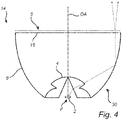
- Figure 4 shows an example of a lighting device 14 which is similar to the one discussed above in connection with figure 2 .
- the light spreading elements 8 are provided on the light exit surface 6 of the collimator 30.
- the light spreading elements 8 can be formed in one piece with the light exit surface 15 or be integrated with of a separate part, such as a plate, which is attached on the light exit surface 15.
- the light spreading elements 8 are adapted to diffuse light, for example through diffusion by transmission or diffusion by metallic reflection.
- Figure 5 shows an example of a lighting device 9 which is similar to the one discussed above in connection with figures 2 and 3 .
- the collimator 300 comprises a first lens 4, which forms the imaging element, and a second lens 10 which is provided with the light spreading elements 5.
- the first lens 4 is configured to form one magnified image of the light source 2 on the second lens 10, but the first lens 4 may be configured to form two or more images in other examples.
- the first lens 4 can for example be a piano convex element or a Fresnel lens.
- the second lens 10 can be a rotationally symmetric collimating lens.
- the second lens can be a freeshape Fresnel lens which allows the direction and spread of light from each point of the light exit surface of the lens to be controlled independently, the light spreading elements then being formed in one piece with the second lens 10.
- the first and second lenses 4, 10 are arranged orthogonal to the optical axis OA and parallel to each other a distance l 1 apart.
- the distance l 1 is usually in the millimeter or centimeter range.
- the distance l 2 between the first lenses 4 and the light source 2 is typically a couple of centimeters.
- the width w 1 of the first lens 4 is usually smaller than the width w 2 of the second lens 10.
- the widths w 1 and w 2 are typically in the millimeter or centimeter range.
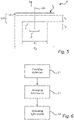
- FIG. 6 is a flowchart of some of the steps of a method for collimating light from a color over position light source 2.
- a collimator 3 similar to the ones discussed above in connection with figures 2 to 4 is provided.
- a CoP light source 2 is arranged on the optical axis of the collimator.
- the light source is put into operation.
- each light spreading element 5 By activating the light source 2, the light source 2 emits light that is received by the collimator 3 by striking the imaging element 4. In each image formed on the light spreading elements 5 by the imaging element 4, light of different colors are spatially separated so that each light spreading element 5 does not receive light of all the colors emitted by the light source 2. Without the imaging element 4, each light spreading element 5 would have receive light from all positions on the light source where light is emitted. Each light spreading element 5 would thus have received light of all the colors emitted by the light source 2 (due to CoP variation).
- the separation of colors be partial in the sense that the colors are only separated in one spatial direction (in which case the imaging element 4 is configured for one dimensional imaging) or in two spatial directions (in which case the imaging element 4 is configured for two dimensional imaging).
- the colors of a light beam are separated in a meridian plane.
- the colors of a light beam are separated in both a meridian plane and a sagittal plane.
- a first light spreading element 11 receives light of a slightly different color than a second light spreading element 12 which is located closer to the light source 2 than the first light spreading element 11.
- the orthogonal distance between the first light spreading element 11 and the optical axis OA is d 1
- the orthogonal distance between the second light spreading element 12 and the optical axis OA is d 2 .
- the first light spreading element 11 is struck by a first light beam 10 which is thereby redirected towards the general direction of illumination I and spread in the meridian plane M, and optionally also in the sagittal plane S, of the first light spreading element 11.
- a second light beam 13 strikes the second light spreading element 12, whereby the second light beam 13 is redirected towards the general direction of illumination I and spread in the meridian plane, and optionally also in the sagittal plane, of the second light spreading element 12.
- the first light spreading element 11 spreads the first light beam 10 so that it covers an angle ⁇ 1 in the meridian plane M.
- the second light spreading element 12 spreads the second light beam 13 so that it covers an angle ⁇ 1 in the meridian plane of the second light spreading element 12.
- the angles covered by the first and second light beams 10, 13 in their respective meridian planes are equal, or approximately equal.
- Rays 11' and 11" illustrate imaging of the center of the light source 2
- rays 13' and 13" illustrate imaging of the edge of the light source 2, i.e. different positions of the light source 2 emitting different colors.
- the first and second light beams 10, 13 are spread in the following way.
- the first light spreading element 11 spreads the first light beam 10 so that it covers an angle ⁇ 1 in the meridian plane M and an angle ⁇ 2 in the sagittal plane S.
- the second light spreading element 12 spreads the second light beam 13 so that it covers an angle ⁇ 1 in the meridian plane of the second light spreading element 12 and an angle ⁇ 2 in the sagittal plane of the second light spreading element 12.
- angles ⁇ 1 and ⁇ 2 may or may not be the same, but the angles covered by the first and second light beams 10, 13 in their respective meridian planes are equal, or approximately equal, and the angles covered by the first and second light beams 10, 13 in their respective sagittal planes are equal, or substantially equal.
- the first and second light beams 10, 13 are thus oriented approximately parallel with the optical axis OA and are about equally spread out in space.
- the light spreading elements 5 spread light beams by creating a respective focal point via a curved surface, wherein light spreading elements 5 having different focal points spread incident light beams differently. This is similar to how lenses work. Further, the greater distance from a light spreading element to the light source 2, the smaller the light source 2 "appears" to the light spreading element. Consequently, had the light beam widening characteristics of the light spreading elements 5 not been position dependent, a light beam leaving the first light spreading element 11 would have been wider than a light beam leaving the second light spreading element 12.
- the stronger light beam widening characteristics of the first light spreading element 11 compensate for the greater distance so that the widths of the first and second light beams 10, 13 match each other in the collimated light, whereby the color of one of the light beams does not dominate over the other in the far field.
Landscapes
- Physics & Mathematics (AREA)
- Optics & Photonics (AREA)
- General Physics & Mathematics (AREA)
- Engineering & Computer Science (AREA)
- Microelectronics & Electronic Packaging (AREA)
- General Engineering & Computer Science (AREA)
- Non-Portable Lighting Devices Or Systems Thereof (AREA)
- Lenses (AREA)
- Optical Head (AREA)
Claims (13)
- Beleuchtungsvorrichtung (1, 9, 14), umfassend einen Kollimator (3, 30, 300) für eine Farbe über die Positionslichtquelle (2), wobei der Kollimator (3, 30, 300) umfasst:einen Brennpunkt (F);eine optische Achse (OA), die den Brennpunkt (F) enthält; eine Farbe über die Positionslichtquelle (2), die auf dem Brennpunkt (F) des Kollimators (3, 30, 300) angeordnet ist, sodass Licht aus der Lichtquelle (2) von dem Kollimator (3, 30, 300) empfangen wird;ein Bildgebungselement (4), das um oder auf der optischen Achse (OA) angeordnet ist, wobei das Bildgebungselement dafür konfiguriert ist, mindestens ein Bild der Lichtquelle zu bilden; undmehrere Lichtausbreitungselemente (5, 11, 12) mit einem ersten Satz von Lichtausbreitungselementen (6) und einen zweiten Satz von Lichtausbreitungselementen (7), wobei sich der erste Satz von Lichtausbreitungselementen (6) weiter von der optischen Achse (OA) und der Lichtquelle (2) befindet als der zweite Satz von Lichtausbreitungselementen (7), die um die optische Achse (OA) herum angeordnet sind, um das mindestens eine Bild von dem Bildgebungselement (4) aufzunehmen,dadurch gekennzeichnet, dass das Bildgebungselement (4) ein erstes Bild der Lichtquelle auf dem ersten Satz von Lichtausbreitungselementen (6) und ein zweites Bild der Lichtquelle auf dem zweiten Satz von
Lichtausbreitungselementen (7) erzeugt,das erste Bild durch Licht gebildet wird, das von der Lichtquelle (2) in einem Winkel kleiner als θ0 in Bezug auf die optische Achse emittiert wird, und ein zweites Bild durch Licht gebildet wird, das in einem Winkel größer als θ0 emittiert wird, und dadurch, dass die Lichtausbreitungselemente (5, 11, 12) unterschiedliche Lichtstrahlaufweitungseigenschaften aufweisen, wobei die Lichtstrahlaufweitungseigenschaften jedes Lichtausbreitungselements (5, 11, 12) der Lichtausbreitungselemente (5, 11, 12) von der Position des Lichtausbreitungselements (5, 11, 12) in Bezug zum Brennpunkt (F) abhängen und wobei die Lichtausbreitungselemente (5, 11, 12) dafür ausgelegt sind, Licht, das auf den ersten Satz von Lichtausbreitungselementen (6) und den zweiten Satz von Lichtausbreitungselementen (7) auftrifft, in einer ersten Ebene (M), die die optische Achse (OA) einschließt, derart auszubreiten, dass es die Strahlaufweitungseigenschaften ermöglichen, dass sich das erste Bild und das zweite Bild über einen im Wesentlichen gleichen Winkel θ1 ausbreiten, aufgrund der Tatsache, dass sich Lichtstrahlen, die unterschiedliche Lichtausbreitungselemente (5, 11, 12) aufweisen, gleichmäßig oder im Wesentlichen gleichmäßig im Raum ausbreiten. - Beleuchtungsvorrichtung nach Anspruch 1, wobei das Bildgebungselement (4) für eine eindimensionale Bildgebung konfiguriert ist.
- Beleuchtungsvorrichtung nach Anspruch 1, wobei das Bildgebungselement (4) für eine zweidimensionale Bildgebung konfiguriert ist.
- Beleuchtungsvorrichtung nach einem der vorstehenden Ansprüche, wobei die Lichtstrahlaufweitungseigenschaften jedes Lichtausbreitungselements (5, 11, 12) von einer optischen Weglänge abhängen, die vom Brennpunkt (F) zum Lichtausbreitungselement (5, 11, 12) gemessen wird.
- Beleuchtungsvorrichtung nach einem der vorstehenden Ansprüche, wobei die Lichtstrahlaufweitungseigenschaften jedes Lichtausbreitungselements (5, 11, 12) vom orthogonalen Abstand von der optischen Achse (OA) zum Lichtausbreitungselement (5, 11, 12) abhängen.
- Beleuchtungsvorrichtung nach einem der vorstehenden Ansprüche, wobei die Lichtausbreitungselemente (5, 11, 12) dafür ausgelegt sind, Licht, das auf die Lichtausbreitungselemente (5, 11, 12) auftrifft, sowohl in der ersten Ebene (M) als auch in einer zweiten Ebene (S) auszubreiten, wobei die zweite Ebene (S) orthogonal zu der ersten Ebene (M) ist und eine Normale orthogonal zur optischen Achse (OA) aufweist.
- Beleuchtungsvorrichtung nach einem der vorstehenden Ansprüche, wobei die Lichtausbreitungselemente (5, 11, 12) Mikrolinsen oder Facetten sind.
- Beleuchtungsvorrichtung nach einem der vorstehenden Ansprüche, wobei die Lichtausbreitungselemente (5, 11, 12) dafür ausgelegt sind, Licht, das auf die Lichtausbreitungselemente (5, 11, 12) auftrifft, auszubreiten, sodass sich Lichtstrahlen, die auf unterschiedliche Lichtausbreitungselemente (5, 11, 12) aufgetroffen sind, gleichmäßig im Raum verteilen.
- Beleuchtungsvorrichtung nach einem der vorstehenden Ansprüche, wobei die Lichtausbreitungselemente (5, 11, 12) auf einer Lichtumlenkfläche (8) des Kollimators (3) bereitgestellt werden.
- Beleuchtungsvorrichtung nach einem der Ansprüche 1 bis 8, wobei die Lichtausbreitungselemente (5, 11, 12) auf einer Lichtaustrittsfläche des Kollimators (30) bereitgestellt werden.
- Beleuchtungsvorrichtung nach einem der Ansprüche 1 bis 8, wobei der Kollimator (300) eine erste Linse (4) und eine zweite Linse (10) umfasst, das Bildgebungselement durch die erste Linse (4) gebildet ist und die Lichtausbreitungselemente (5, 11, 12) auf der zweiten Linse (10) bereitgestellt werden.
- Beleuchtungsvorrichtung nach Anspruch 1, wobei das Bildgebungselement dafür konfiguriert ist, mindestens zwei vergrößerte Bilder der Lichtquelle zu bilden, einschließlich eines ersten Bildes, das auf einem ersten Satz von Lichtausbreitungselementen (6) erzeugt wird, und eines zweiten Bildes, das auf einem zweiten Satz von Lichtausbreitungselementen (7) erzeugt wird, wobei sich der erste Satz von Lichtausbreitungselementen (6) weiter von der optischen Achse (OA) und der Lichtquelle (2) befindet als der zweite Satz von Lichtausbreitungselementen (7)
- Verfahren zum Kollimieren von Licht aus einer Farbe über einer Positionslichtquelle (2), wobei das Verfahren umfasst:Bereitstellen eines Kollimators (3, 30, 300), der einschließt: einen Brennpunkt (F); eine optische Achse (OA), die den Brennpunkt (F) enthält; ein Bildgebungselement (4), das um oder auf der optischen Achse (OA) angeordnet ist, und Bereitstellen einer Farbe über einer Positionslichtquelle (2), die auf dem Brennpunkt (F) des Kollimators (3, 30, 300) angeordnet ist, sodass Licht von der Lichtquelle (2) von dem Kollimator (3, 30, 300) empfangen wird, wobei das Bildgebungselement dafür konfiguriert ist, mindestens ein Bild der Lichtquelle zu bilden; und mehrere Lichtausbreitungselemente (5, 11, 12) mit einem ersten Satz von Lichtausbreitungselementen (6) und einem zweiten Satz von Lichtausbreitungselementen (7), wobei sich der erste Satz von Lichtausbreitungselementen (6) weiter von der optischen Achse (OA) und der Lichtquelle (2) befindet als der zweite Satz von Lichtausbreitungselementen (7), die um die optische Achse (OA) herum angeordnet sind, um das mindestens eine Bild von dem Bildgebungselement (4) zu empfangen, wobei das Bildgebungselement (4) ein erstes Bild der Lichtquelle auf dem ersten Satz von Lichtausbreitungselementen (6) und ein zweites Bild der Lichtquelle auf dem zweiten Satz von Lichtausbreitungselementen (7) erzeugt, wobei das erste Bild durch Licht gebildet wird, das von der Lichtquelle (2) in einem Winkel kleiner als θ0 in Bezug auf die optische Achse emittiert wird, und ein zweites Bild durch Licht gebildet wird, das in einem Winkel größer als θ0 emittiert wird, wobei die Lichtausbreitungselemente (5, 11, 12) unterschiedliche Lichtstrahlaufweitungseigenschaften aufweisen, wobei die Lichtstrahlaufweitungseigenschaften jedes Lichtausbreitungselements (5, 11, 12) der Lichtausbreitungselemente (5, 11, 12) von der Position des Lichtausbreitungselements (5, 11, 12) in Bezug zum Brennpunkt (F) abhängen, und wobei die Lichtausbreitungselemente (5, 11, 12) dafür ausgelegt sind, Licht, das auf den ersten Satz von Lichtausbreitungselementen (6) und den zweiten Satz von Lichtausbreitungselementen (7) in einer ersten Ebene (M) auftrifft, die eine optische Achse (OA) einschließt, derart auszubreiten, dass die Strahlaufweitungseigenschaften ermöglichen, dass sich das erste Bild und das zweite Bild über einen im Wesentlichen gleichen Winkel θ0 ausbreiten, aufgrund der Tatsache, dass sich Lichtstrahlen, die auf unterschiedliche Lichtausbreitungselemente (5, 11, 12) auftreffen, gleichmäßig oder im Wesentlichen gleichmäßig im Raum ausbreiten;Anordnen der Lichtquelle (2) auf dem Brennpunkt (F) des Kollimators (3, 30, 300); undBetreiben der Lichtquelle (2),wobei die Lichtausbreitungselemente (5, 11, 12) das mindestens eine Bild der Lichtquelle (2) von dem Bildgebungselement (4) empfängt und wobei Licht, das auf die Lichtausbreitungselemente (5, 11, 12) auftrifft, in einer ersten Ebene (M), die die optische Achse (OA) einschließt, ausgebreitet wird.
Applications Claiming Priority (2)
| Application Number | Priority Date | Filing Date | Title |
|---|---|---|---|
| EP15153895 | 2015-02-05 | ||
| PCT/EP2016/051578 WO2016124449A1 (en) | 2015-02-05 | 2016-01-26 | Color correcting collimation of light from a color over position light source |
Publications (2)
| Publication Number | Publication Date |
|---|---|
| EP3265862A1 EP3265862A1 (de) | 2018-01-10 |
| EP3265862B1 true EP3265862B1 (de) | 2022-03-30 |
Family
ID=52444209
Family Applications (1)
| Application Number | Title | Priority Date | Filing Date |
|---|---|---|---|
| EP16701634.4A Active EP3265862B1 (de) | 2015-02-05 | 2016-01-26 | Farbkorrekturkollimation von licht aus einer winkelfarblichtpositionsquelle |
Country Status (5)
| Country | Link |
|---|---|
| US (1) | US10761308B2 (de) |
| EP (1) | EP3265862B1 (de) |
| JP (1) | JP6659707B2 (de) |
| CN (1) | CN107209355B (de) |
| WO (1) | WO2016124449A1 (de) |
Families Citing this family (2)
| Publication number | Priority date | Publication date | Assignee | Title |
|---|---|---|---|---|
| DE102018123789A1 (de) * | 2018-09-26 | 2020-03-26 | Carl Zeiss Jena Gmbh | Leuchteinrichtung für ein Fahrzeug |
| CN114945301A (zh) * | 2021-03-24 | 2022-08-26 | 深圳汝原科技有限公司 | 辐射源、干燥设备和反光座 |
Family Cites Families (21)
| Publication number | Priority date | Publication date | Assignee | Title |
|---|---|---|---|---|
| HUT51019A (en) * | 1987-01-19 | 1990-03-28 | Proizv Ob Avtotraktor Elekt N | Light-emitting apparatus |
| US8136967B2 (en) * | 2008-03-02 | 2012-03-20 | Lumenetix, Inc. | LED optical lens |
| JP5081708B2 (ja) * | 2008-04-24 | 2012-11-28 | パナソニック株式会社 | レンズ付発光ユニット |
| JP5279329B2 (ja) * | 2008-04-24 | 2013-09-04 | パナソニック株式会社 | レンズ付発光ユニット |
| CN106152004A (zh) * | 2008-08-18 | 2016-11-23 | 香港理工大学 | Led汽车尾灯组 |
| CN101660717B (zh) * | 2008-08-25 | 2011-04-20 | 沈阳仪表科学研究院 | 无影灯宽角度调色温冷反射镜 |
| US9164268B2 (en) * | 2009-02-03 | 2015-10-20 | Fraen Corporation | Light mixing optics and systems |
| US20110012147A1 (en) | 2009-07-15 | 2011-01-20 | Koninklijke Philips Electronics N.V. | Wavelength-converted semiconductor light emitting device including a filter and a scattering structure |
| US8803171B2 (en) | 2009-07-22 | 2014-08-12 | Koninklijke Philips N.V. | Reduced color over angle variation LEDs |
| EP2550481B1 (de) * | 2010-03-23 | 2020-05-06 | Lumileds Holding B.V. | Integrale beleuchtungsanordnung |
| US8789983B2 (en) * | 2011-04-22 | 2014-07-29 | William A. Parkyn | Free-form catadioptric illumination lens |
| CN102954440A (zh) * | 2011-08-29 | 2013-03-06 | 惠州元晖光电股份有限公司 | 可用于多芯片半导体led照明的二次配光透镜 |
| US8740417B2 (en) * | 2011-09-01 | 2014-06-03 | Huizhou Light Engine Limited | Secondary light distribution lens for multi-chip semiconductor (LED) lighting |
| WO2013035036A1 (en) | 2011-09-09 | 2013-03-14 | Koninklijke Philips Electronics N.V. | A collimator structure and lighting device |
| CN103292247B (zh) * | 2012-02-29 | 2015-05-20 | 惠州元晖光电股份有限公司 | 一种多面体的二次光学透镜 |
| JP2013214449A (ja) * | 2012-04-03 | 2013-10-17 | Yuichi Suzuki | トロイダルレンズおよび照明装置 |
| JP6165234B2 (ja) | 2012-04-25 | 2017-07-19 | フィリップス ライティング ホールディング ビー ヴィ | 色補正光学素子 |
| JP5910324B2 (ja) * | 2012-06-04 | 2016-04-27 | ソニー株式会社 | 照明装置、投影型表示装置および直視型表示装置 |
| US8591074B1 (en) * | 2012-09-05 | 2013-11-26 | Top International Enterprise Limited | Secondary optical lens |
| JP2014130212A (ja) * | 2012-12-28 | 2014-07-10 | Konica Minolta Inc | 光学素子及び照明装置 |
| CN103441178B (zh) * | 2013-09-10 | 2016-07-06 | 浙江大学 | 基于复眼的紧凑式双反射型光伏聚光器 |
-
2016
- 2016-01-26 JP JP2017541242A patent/JP6659707B2/ja active Active
- 2016-01-26 EP EP16701634.4A patent/EP3265862B1/de active Active
- 2016-01-26 CN CN201680008783.5A patent/CN107209355B/zh active Active
- 2016-01-26 US US15/548,323 patent/US10761308B2/en active Active
- 2016-01-26 WO PCT/EP2016/051578 patent/WO2016124449A1/en active Application Filing
Also Published As
| Publication number | Publication date |
|---|---|
| US10761308B2 (en) | 2020-09-01 |
| WO2016124449A8 (en) | 2017-09-28 |
| JP2018504761A (ja) | 2018-02-15 |
| EP3265862A1 (de) | 2018-01-10 |
| WO2016124449A1 (en) | 2016-08-11 |
| CN107209355A (zh) | 2017-09-26 |
| CN107209355B (zh) | 2020-09-11 |
| US20180024337A1 (en) | 2018-01-25 |
| JP6659707B2 (ja) | 2020-03-04 |
Similar Documents
| Publication | Publication Date | Title |
|---|---|---|
| JP5050149B1 (ja) | 照明装置 | |
| JP5957364B2 (ja) | 光束制御部材、発光装置、面光源装置および表示装置 | |
| EP3070510B1 (de) | Head-up display, beleuchtungsvorrichtung und fahrzeug mit selbigem ausgestattet | |
| JP7065608B2 (ja) | 光学装置、照明システム及び光学ビームを成形する方法 | |
| EP2351963B1 (de) | Beleuchtungsvorrichtung für ein fahrzeug | |
| US10061121B2 (en) | Optical structure for vehicle | |
| US10724692B2 (en) | Light source unit | |
| US20170115531A1 (en) | Light flux control member, light-emitting device, planar light source device and display device | |
| US10851960B2 (en) | Vehicular lighting fixture | |
| JP2017009864A (ja) | 液晶表示装置 | |
| JP2018083593A (ja) | 表示装置 | |
| JP2018098162A (ja) | 面光源装置および表示装置 | |
| JP2014211983A (ja) | 車両用灯具の灯具ユニット | |
| EP3265862B1 (de) | Farbkorrekturkollimation von licht aus einer winkelfarblichtpositionsquelle | |
| US11054102B2 (en) | Collimator lens, light radiation device, and vehicle lighting apparatus | |
| US10180233B2 (en) | Luminaire with a light diffuser | |
| JP6748424B2 (ja) | 発光装置、面光源装置および表示装置 | |
| WO2017002725A1 (ja) | 発光装置、面光源装置および表示装置 | |
| JP2010140745A (ja) | 照明装置、及び投射型画像表示装置 | |
| JP2017500700A (ja) | 照明デバイス | |
| US10941917B2 (en) | Lighting tool for vehicle | |
| JP6405060B2 (ja) | 管状発光装置 | |
| WO2018186413A1 (ja) | 導光体、及び面状発光モジュール | |
| JP2021015782A (ja) | 照明装置 |
Legal Events
| Date | Code | Title | Description |
|---|---|---|---|
| STAA | Information on the status of an ep patent application or granted ep patent |
Free format text: STATUS: THE INTERNATIONAL PUBLICATION HAS BEEN MADE |
|
| PUAI | Public reference made under article 153(3) epc to a published international application that has entered the european phase |
Free format text: ORIGINAL CODE: 0009012 |
|
| STAA | Information on the status of an ep patent application or granted ep patent |
Free format text: STATUS: REQUEST FOR EXAMINATION WAS MADE |
|
| 17P | Request for examination filed |
Effective date: 20170905 |
|
| AK | Designated contracting states |
Kind code of ref document: A1 Designated state(s): AL AT BE BG CH CY CZ DE DK EE ES FI FR GB GR HR HU IE IS IT LI LT LU LV MC MK MT NL NO PL PT RO RS SE SI SK SM TR |
|
| AX | Request for extension of the european patent |
Extension state: BA ME |
|
| DAV | Request for validation of the european patent (deleted) | ||
| DAX | Request for extension of the european patent (deleted) | ||
| RAP1 | Party data changed (applicant data changed or rights of an application transferred) |
Owner name: PHILIPS LIGHTING HOLDING B.V. |
|
| RAP1 | Party data changed (applicant data changed or rights of an application transferred) |
Owner name: SIGNIFY HOLDING B.V. |
|
| STAA | Information on the status of an ep patent application or granted ep patent |
Free format text: STATUS: EXAMINATION IS IN PROGRESS |
|
| 17Q | First examination report despatched |
Effective date: 20200529 |
|
| STAA | Information on the status of an ep patent application or granted ep patent |
Free format text: STATUS: EXAMINATION IS IN PROGRESS |
|
| GRAP | Despatch of communication of intention to grant a patent |
Free format text: ORIGINAL CODE: EPIDOSNIGR1 |
|
| STAA | Information on the status of an ep patent application or granted ep patent |
Free format text: STATUS: GRANT OF PATENT IS INTENDED |
|
| INTG | Intention to grant announced |
Effective date: 20211104 |
|
| GRAS | Grant fee paid |
Free format text: ORIGINAL CODE: EPIDOSNIGR3 |
|
| GRAA | (expected) grant |
Free format text: ORIGINAL CODE: 0009210 |
|
| STAA | Information on the status of an ep patent application or granted ep patent |
Free format text: STATUS: THE PATENT HAS BEEN GRANTED |
|
| AK | Designated contracting states |
Kind code of ref document: B1 Designated state(s): AL AT BE BG CH CY CZ DE DK EE ES FI FR GB GR HR HU IE IS IT LI LT LU LV MC MK MT NL NO PL PT RO RS SE SI SK SM TR |
|
| REG | Reference to a national code |
Ref country code: GB Ref legal event code: FG4D |
|
| REG | Reference to a national code |
Ref country code: CH Ref legal event code: EP |
|
| REG | Reference to a national code |
Ref country code: AT Ref legal event code: REF Ref document number: 1479741 Country of ref document: AT Kind code of ref document: T Effective date: 20220415 |
|
| REG | Reference to a national code |
Ref country code: DE Ref legal event code: R096 Ref document number: 602016070457 Country of ref document: DE |
|
| REG | Reference to a national code |
Ref country code: IE Ref legal event code: FG4D |
|
| REG | Reference to a national code |
Ref country code: LT Ref legal event code: MG9D |
|
| PG25 | Lapsed in a contracting state [announced via postgrant information from national office to epo] |
Ref country code: SE Free format text: LAPSE BECAUSE OF FAILURE TO SUBMIT A TRANSLATION OF THE DESCRIPTION OR TO PAY THE FEE WITHIN THE PRESCRIBED TIME-LIMIT Effective date: 20220330 Ref country code: RS Free format text: LAPSE BECAUSE OF FAILURE TO SUBMIT A TRANSLATION OF THE DESCRIPTION OR TO PAY THE FEE WITHIN THE PRESCRIBED TIME-LIMIT Effective date: 20220330 Ref country code: NO Free format text: LAPSE BECAUSE OF FAILURE TO SUBMIT A TRANSLATION OF THE DESCRIPTION OR TO PAY THE FEE WITHIN THE PRESCRIBED TIME-LIMIT Effective date: 20220630 Ref country code: LT Free format text: LAPSE BECAUSE OF FAILURE TO SUBMIT A TRANSLATION OF THE DESCRIPTION OR TO PAY THE FEE WITHIN THE PRESCRIBED TIME-LIMIT Effective date: 20220330 Ref country code: HR Free format text: LAPSE BECAUSE OF FAILURE TO SUBMIT A TRANSLATION OF THE DESCRIPTION OR TO PAY THE FEE WITHIN THE PRESCRIBED TIME-LIMIT Effective date: 20220330 Ref country code: BG Free format text: LAPSE BECAUSE OF FAILURE TO SUBMIT A TRANSLATION OF THE DESCRIPTION OR TO PAY THE FEE WITHIN THE PRESCRIBED TIME-LIMIT Effective date: 20220630 |
|
| REG | Reference to a national code |
Ref country code: NL Ref legal event code: MP Effective date: 20220330 |
|
| REG | Reference to a national code |
Ref country code: AT Ref legal event code: MK05 Ref document number: 1479741 Country of ref document: AT Kind code of ref document: T Effective date: 20220330 |
|
| PG25 | Lapsed in a contracting state [announced via postgrant information from national office to epo] |
Ref country code: LV Free format text: LAPSE BECAUSE OF FAILURE TO SUBMIT A TRANSLATION OF THE DESCRIPTION OR TO PAY THE FEE WITHIN THE PRESCRIBED TIME-LIMIT Effective date: 20220330 Ref country code: GR Free format text: LAPSE BECAUSE OF FAILURE TO SUBMIT A TRANSLATION OF THE DESCRIPTION OR TO PAY THE FEE WITHIN THE PRESCRIBED TIME-LIMIT Effective date: 20220701 Ref country code: FI Free format text: LAPSE BECAUSE OF FAILURE TO SUBMIT A TRANSLATION OF THE DESCRIPTION OR TO PAY THE FEE WITHIN THE PRESCRIBED TIME-LIMIT Effective date: 20220330 |
|
| PG25 | Lapsed in a contracting state [announced via postgrant information from national office to epo] |
Ref country code: NL Free format text: LAPSE BECAUSE OF FAILURE TO SUBMIT A TRANSLATION OF THE DESCRIPTION OR TO PAY THE FEE WITHIN THE PRESCRIBED TIME-LIMIT Effective date: 20220330 |
|
| PG25 | Lapsed in a contracting state [announced via postgrant information from national office to epo] |
Ref country code: SM Free format text: LAPSE BECAUSE OF FAILURE TO SUBMIT A TRANSLATION OF THE DESCRIPTION OR TO PAY THE FEE WITHIN THE PRESCRIBED TIME-LIMIT Effective date: 20220330 Ref country code: SK Free format text: LAPSE BECAUSE OF FAILURE TO SUBMIT A TRANSLATION OF THE DESCRIPTION OR TO PAY THE FEE WITHIN THE PRESCRIBED TIME-LIMIT Effective date: 20220330 Ref country code: RO Free format text: LAPSE BECAUSE OF FAILURE TO SUBMIT A TRANSLATION OF THE DESCRIPTION OR TO PAY THE FEE WITHIN THE PRESCRIBED TIME-LIMIT Effective date: 20220330 Ref country code: PT Free format text: LAPSE BECAUSE OF FAILURE TO SUBMIT A TRANSLATION OF THE DESCRIPTION OR TO PAY THE FEE WITHIN THE PRESCRIBED TIME-LIMIT Effective date: 20220801 Ref country code: ES Free format text: LAPSE BECAUSE OF FAILURE TO SUBMIT A TRANSLATION OF THE DESCRIPTION OR TO PAY THE FEE WITHIN THE PRESCRIBED TIME-LIMIT Effective date: 20220330 Ref country code: EE Free format text: LAPSE BECAUSE OF FAILURE TO SUBMIT A TRANSLATION OF THE DESCRIPTION OR TO PAY THE FEE WITHIN THE PRESCRIBED TIME-LIMIT Effective date: 20220330 Ref country code: CZ Free format text: LAPSE BECAUSE OF FAILURE TO SUBMIT A TRANSLATION OF THE DESCRIPTION OR TO PAY THE FEE WITHIN THE PRESCRIBED TIME-LIMIT Effective date: 20220330 Ref country code: AT Free format text: LAPSE BECAUSE OF FAILURE TO SUBMIT A TRANSLATION OF THE DESCRIPTION OR TO PAY THE FEE WITHIN THE PRESCRIBED TIME-LIMIT Effective date: 20220330 |
|
| PG25 | Lapsed in a contracting state [announced via postgrant information from national office to epo] |
Ref country code: PL Free format text: LAPSE BECAUSE OF FAILURE TO SUBMIT A TRANSLATION OF THE DESCRIPTION OR TO PAY THE FEE WITHIN THE PRESCRIBED TIME-LIMIT Effective date: 20220330 Ref country code: IS Free format text: LAPSE BECAUSE OF FAILURE TO SUBMIT A TRANSLATION OF THE DESCRIPTION OR TO PAY THE FEE WITHIN THE PRESCRIBED TIME-LIMIT Effective date: 20220730 Ref country code: AL Free format text: LAPSE BECAUSE OF FAILURE TO SUBMIT A TRANSLATION OF THE DESCRIPTION OR TO PAY THE FEE WITHIN THE PRESCRIBED TIME-LIMIT Effective date: 20220330 |
|
| REG | Reference to a national code |
Ref country code: DE Ref legal event code: R097 Ref document number: 602016070457 Country of ref document: DE |
|
| PG25 | Lapsed in a contracting state [announced via postgrant information from national office to epo] |
Ref country code: DK Free format text: LAPSE BECAUSE OF FAILURE TO SUBMIT A TRANSLATION OF THE DESCRIPTION OR TO PAY THE FEE WITHIN THE PRESCRIBED TIME-LIMIT Effective date: 20220330 |
|
| PLBE | No opposition filed within time limit |
Free format text: ORIGINAL CODE: 0009261 |
|
| STAA | Information on the status of an ep patent application or granted ep patent |
Free format text: STATUS: NO OPPOSITION FILED WITHIN TIME LIMIT |
|
| 26N | No opposition filed |
Effective date: 20230103 |
|
| PG25 | Lapsed in a contracting state [announced via postgrant information from national office to epo] |
Ref country code: SI Free format text: LAPSE BECAUSE OF FAILURE TO SUBMIT A TRANSLATION OF THE DESCRIPTION OR TO PAY THE FEE WITHIN THE PRESCRIBED TIME-LIMIT Effective date: 20220330 |
|
| P01 | Opt-out of the competence of the unified patent court (upc) registered |
Effective date: 20230425 |
|
| PG25 | Lapsed in a contracting state [announced via postgrant information from national office to epo] |
Ref country code: IT Free format text: LAPSE BECAUSE OF FAILURE TO SUBMIT A TRANSLATION OF THE DESCRIPTION OR TO PAY THE FEE WITHIN THE PRESCRIBED TIME-LIMIT Effective date: 20220330 |
|
| REG | Reference to a national code |
Ref country code: CH Ref legal event code: PL |
|
| PG25 | Lapsed in a contracting state [announced via postgrant information from national office to epo] |
Ref country code: LU Free format text: LAPSE BECAUSE OF NON-PAYMENT OF DUE FEES Effective date: 20230126 |
|
| REG | Reference to a national code |
Ref country code: BE Ref legal event code: MM Effective date: 20230131 |
|
| PG25 | Lapsed in a contracting state [announced via postgrant information from national office to epo] |
Ref country code: LI Free format text: LAPSE BECAUSE OF NON-PAYMENT OF DUE FEES Effective date: 20230131 Ref country code: CH Free format text: LAPSE BECAUSE OF NON-PAYMENT OF DUE FEES Effective date: 20230131 |
|
| PG25 | Lapsed in a contracting state [announced via postgrant information from national office to epo] |
Ref country code: BE Free format text: LAPSE BECAUSE OF NON-PAYMENT OF DUE FEES Effective date: 20230131 |
|
| PG25 | Lapsed in a contracting state [announced via postgrant information from national office to epo] |
Ref country code: IE Free format text: LAPSE BECAUSE OF NON-PAYMENT OF DUE FEES Effective date: 20230126 |
|
| PGFP | Annual fee paid to national office [announced via postgrant information from national office to epo] |
Ref country code: DE Payment date: 20240328 Year of fee payment: 9 Ref country code: GB Payment date: 20240123 Year of fee payment: 9 |
|
| PGFP | Annual fee paid to national office [announced via postgrant information from national office to epo] |
Ref country code: FR Payment date: 20240125 Year of fee payment: 9 |
|
| PG25 | Lapsed in a contracting state [announced via postgrant information from national office to epo] |
Ref country code: MC Free format text: LAPSE BECAUSE OF FAILURE TO SUBMIT A TRANSLATION OF THE DESCRIPTION OR TO PAY THE FEE WITHIN THE PRESCRIBED TIME-LIMIT Effective date: 20220330 |
|
| PG25 | Lapsed in a contracting state [announced via postgrant information from national office to epo] |
Ref country code: MC Free format text: LAPSE BECAUSE OF FAILURE TO SUBMIT A TRANSLATION OF THE DESCRIPTION OR TO PAY THE FEE WITHIN THE PRESCRIBED TIME-LIMIT Effective date: 20220330 |