EP3264968B1 - Single piece bending neck for an articulating ultrasound probe - Google Patents
Single piece bending neck for an articulating ultrasound probe Download PDFInfo
- Publication number
- EP3264968B1 EP3264968B1 EP16709591.8A EP16709591A EP3264968B1 EP 3264968 B1 EP3264968 B1 EP 3264968B1 EP 16709591 A EP16709591 A EP 16709591A EP 3264968 B1 EP3264968 B1 EP 3264968B1
- Authority
- EP
- European Patent Office
- Prior art keywords
- links
- tube
- pivot
- pair
- section
- Prior art date
- Legal status (The legal status is an assumption and is not a legal conclusion. Google has not performed a legal analysis and makes no representation as to the accuracy of the status listed.)
- Active
Links
Images
Classifications
-
- A—HUMAN NECESSITIES
- A61—MEDICAL OR VETERINARY SCIENCE; HYGIENE
- A61B—DIAGNOSIS; SURGERY; IDENTIFICATION
- A61B1/00—Instruments for performing medical examinations of the interior of cavities or tubes of the body by visual or photographical inspection, e.g. endoscopes; Illuminating arrangements therefor
- A61B1/00064—Constructional details of the endoscope body
- A61B1/0011—Manufacturing of endoscope parts
-
- A—HUMAN NECESSITIES
- A61—MEDICAL OR VETERINARY SCIENCE; HYGIENE
- A61B—DIAGNOSIS; SURGERY; IDENTIFICATION
- A61B1/00—Instruments for performing medical examinations of the interior of cavities or tubes of the body by visual or photographical inspection, e.g. endoscopes; Illuminating arrangements therefor
- A61B1/005—Flexible endoscopes
- A61B1/0051—Flexible endoscopes with controlled bending of insertion part
- A61B1/0055—Constructional details of insertion parts, e.g. vertebral elements
-
- A—HUMAN NECESSITIES
- A61—MEDICAL OR VETERINARY SCIENCE; HYGIENE
- A61B—DIAGNOSIS; SURGERY; IDENTIFICATION
- A61B1/00—Instruments for performing medical examinations of the interior of cavities or tubes of the body by visual or photographical inspection, e.g. endoscopes; Illuminating arrangements therefor
- A61B1/005—Flexible endoscopes
- A61B1/0051—Flexible endoscopes with controlled bending of insertion part
- A61B1/0057—Constructional details of force transmission elements, e.g. control wires
-
- A—HUMAN NECESSITIES
- A61—MEDICAL OR VETERINARY SCIENCE; HYGIENE
- A61B—DIAGNOSIS; SURGERY; IDENTIFICATION
- A61B1/00—Instruments for performing medical examinations of the interior of cavities or tubes of the body by visual or photographical inspection, e.g. endoscopes; Illuminating arrangements therefor
- A61B1/005—Flexible endoscopes
- A61B1/008—Articulations
-
- A—HUMAN NECESSITIES
- A61—MEDICAL OR VETERINARY SCIENCE; HYGIENE
- A61B—DIAGNOSIS; SURGERY; IDENTIFICATION
- A61B8/00—Diagnosis using ultrasonic, sonic or infrasonic waves
- A61B8/12—Diagnosis using ultrasonic, sonic or infrasonic waves in body cavities or body tracts, e.g. by using catheters
-
- A—HUMAN NECESSITIES
- A61—MEDICAL OR VETERINARY SCIENCE; HYGIENE
- A61B—DIAGNOSIS; SURGERY; IDENTIFICATION
- A61B8/00—Diagnosis using ultrasonic, sonic or infrasonic waves
- A61B8/44—Constructional features of the ultrasonic, sonic or infrasonic diagnostic device
- A61B8/4444—Constructional features of the ultrasonic, sonic or infrasonic diagnostic device related to the probe
- A61B8/445—Details of catheter construction
-
- A—HUMAN NECESSITIES
- A61—MEDICAL OR VETERINARY SCIENCE; HYGIENE
- A61M—DEVICES FOR INTRODUCING MEDIA INTO, OR ONTO, THE BODY; DEVICES FOR TRANSDUCING BODY MEDIA OR FOR TAKING MEDIA FROM THE BODY; DEVICES FOR PRODUCING OR ENDING SLEEP OR STUPOR
- A61M25/00—Catheters; Hollow probes
- A61M25/01—Introducing, guiding, advancing, emplacing or holding catheters
- A61M25/0105—Steering means as part of the catheter or advancing means; Markers for positioning
- A61M25/0133—Tip steering devices
- A61M25/0138—Tip steering devices having flexible regions as a result of weakened outer material, e.g. slots, slits, cuts, joints or coils
-
- A—HUMAN NECESSITIES
- A61—MEDICAL OR VETERINARY SCIENCE; HYGIENE
- A61M—DEVICES FOR INTRODUCING MEDIA INTO, OR ONTO, THE BODY; DEVICES FOR TRANSDUCING BODY MEDIA OR FOR TAKING MEDIA FROM THE BODY; DEVICES FOR PRODUCING OR ENDING SLEEP OR STUPOR
- A61M25/00—Catheters; Hollow probes
- A61M25/01—Introducing, guiding, advancing, emplacing or holding catheters
- A61M25/0105—Steering means as part of the catheter or advancing means; Markers for positioning
- A61M25/0133—Tip steering devices
- A61M25/0147—Tip steering devices with movable mechanical means, e.g. pull wires
-
- A—HUMAN NECESSITIES
- A61—MEDICAL OR VETERINARY SCIENCE; HYGIENE
- A61B—DIAGNOSIS; SURGERY; IDENTIFICATION
- A61B1/00—Instruments for performing medical examinations of the interior of cavities or tubes of the body by visual or photographical inspection, e.g. endoscopes; Illuminating arrangements therefor
- A61B1/00064—Constructional details of the endoscope body
- A61B1/00071—Insertion part of the endoscope body
- A61B1/00078—Insertion part of the endoscope body with stiffening means
-
- A—HUMAN NECESSITIES
- A61—MEDICAL OR VETERINARY SCIENCE; HYGIENE
- A61B—DIAGNOSIS; SURGERY; IDENTIFICATION
- A61B17/00—Surgical instruments, devices or methods
- A61B17/00234—Surgical instruments, devices or methods for minimally invasive surgery
- A61B2017/00292—Surgical instruments, devices or methods for minimally invasive surgery mounted on or guided by flexible, e.g. catheter-like, means
- A61B2017/003—Steerable
- A61B2017/00305—Constructional details of the flexible means
- A61B2017/00314—Separate linked members
-
- A—HUMAN NECESSITIES
- A61—MEDICAL OR VETERINARY SCIENCE; HYGIENE
- A61B—DIAGNOSIS; SURGERY; IDENTIFICATION
- A61B17/00—Surgical instruments, devices or methods
- A61B17/00234—Surgical instruments, devices or methods for minimally invasive surgery
- A61B2017/00292—Surgical instruments, devices or methods for minimally invasive surgery mounted on or guided by flexible, e.g. catheter-like, means
- A61B2017/003—Steerable
- A61B2017/00318—Steering mechanisms
- A61B2017/00323—Cables or rods
- A61B2017/00327—Cables or rods with actuating members moving in opposite directions
-
- A—HUMAN NECESSITIES
- A61—MEDICAL OR VETERINARY SCIENCE; HYGIENE
- A61M—DEVICES FOR INTRODUCING MEDIA INTO, OR ONTO, THE BODY; DEVICES FOR TRANSDUCING BODY MEDIA OR FOR TAKING MEDIA FROM THE BODY; DEVICES FOR PRODUCING OR ENDING SLEEP OR STUPOR
- A61M25/00—Catheters; Hollow probes
- A61M25/01—Introducing, guiding, advancing, emplacing or holding catheters
- A61M25/0105—Steering means as part of the catheter or advancing means; Markers for positioning
- A61M25/0133—Tip steering devices
- A61M2025/0161—Tip steering devices wherein the distal tips have two or more deflection regions
Definitions
- This invention relates to ultrasonic imaging probes and, in particular, to bending necks for articulating ultrasound probes.
- Some ultrasound probes are designed for imaging from within the body, including catheter probes and transesophageal echocardiography (TEE) probes.
- TEE transesophageal echocardiography
- the imaging transducer is located at the tip of the probe, which is generally designed to be articulated by the operator so as to obtain the desired view.
- the preferred way to articulate the probe tip is by means of a distal section of the catheter or gastroscope referred to as a bending neck.
- the bending neck is formed by a series of links which are pivotally connected to each other. This enables each link to move slightly with respect to its adjoining links and hence the entire section of links can be made to controllably articulate over a substantial angle of bending.
- Control of the articulation is done by cables extending through the probe and the bending neck which are wrapped about the shaft or pulley of a control knob or motor in the control unit at the proximal end of the probe.
- a desired cable is pulled, which bends the articulating neck section of the probe.
- the pivot axis between links alternates by 90° from link to link so that some axes can bend in the 0°-180° directions while the others can bend in the 90°-270° directions.
- the use of two controls and control cables for these two axis directions enables the operator to articulate the bending neck in any of these directions or any direction in between.
- the links and hence the bending neck is hollow, enabling the wiring for the transducer at the distal tip as well as other items such as guide wires and surgical tools to pass through the probe for operation at or through the tip of the probe.
- a bending portion of an endoscope that includes a bending piece set in which a plurality of bending pieces are continuously provided by forming a convex portion on a first bending piece and a concave portion on a second bending piece by cutting a rigid pipe.
- the convex portion and the concave portion form an engagement portion that pivotably couples adjacent bending pieces to each other.
- Patent application publication US 2010/0287755 A1 relates a method for manufacturing a bendable tube, which is preferably envisaged for an endoscopic instrument.
- a tube is separated into several tube sections in a manner such that adjacent tube sections engage into one another with a positive fit in the axis direction of the tube.
- means for providing a positive fit transversely to the axis direction of the tube are peripherally arranged on the regions of the tube sections, which are situated in engagement with one another.
- a bending neck for a controllably articulating ultrasound probe which is formed from a single tube or nested tube set.
- the tube is etched or machined to form individual, pivoting links.
- a groove formed in one of the tubes of the nested tube set, or indentations in a single tube provide the control cable passageway.
- the bending neck curvature is formed to be variable, as by the use of movable bending points, multiple control cable anchor points, varying pivot axis spacing, and multi-durometer neck sheaths.
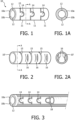
- a single piece bending neck 10 for an articulating ultrasound probe is shown which is formed of two concentric tubes, generally made of a metal such as stainless steel.
- the inner tube 10b fits tightly within the outer tube 10a.
- two longitudinal grooves 12 are formed on opposite sides along the length of the outside of tube 10b. These grooves form passageways for control cables that control the articulation of the bending neck as described below.
- the grooves 12 are clearly shown in the cross-sectional view of FIGURE 1A . With the two tubes concentrically positioned, they are then cut into separate links 11 by laser cutting toward the longitudinal axis of the tube or by another machining technique.
- the links are formed so as to remain movably connected to each other, as by lobes 14 extending from one link to the next and located on opposite sides of the links. These lobes and the spacing between the links formed by the machining process enable the adjacent links to move and pivot with respect to each other about axes extending through opposing lobes on opposite sides of the links. While each link may only pivot a small angle with respect to its neighbor, a number of successive links forming a bending neck may together bend in a considerable curve. This is the desired articulation, significant enough to be able to position the distal end of the probe where needed, but not sharp enough at any articular point so as to bind the wires, tools, and other items passing through the central lumen of the bending neck.
- FIGURE 2 illustrates a second implementation of a single piece bending neck, this time using just a single tube 10'.
- the tube 10' is machined into separate connected links as described above, the grooves 15 between separate links being shown in this drawing. Since the inner tube used for the control cable groove is not present in this single tube implementation, a series of ring-like indentations 16 are formed on opposite sides of the tube to convey the control cables through the bending neck. Two parallel cuts are made through the tube wall, then the area between the cuts is pressed inward, forming the indentations as clearly shown in the cross-sectional view of FIGURE 2A .
- the indentations are formed on the tube sides which are 90° around the tube from the lines of pivot lobes 14, which are on the top and bottom and cannot be seen in the view of FIGURE 2 .
- As the control cables passing though the indentations on opposite sides of the tube are pulled after being anchored at the distal end of the bending neck. They will respectively cause the neck to bend into and out of the plane of the drawing of FIGURE 2 .
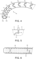
- FIGURE 3 illustrates a technique in which a rigid member 18 is located in the bending neck with its distal end at the desired deflection point.
- the rigid member is a tube 18 and this partially cut-away view shows links to the left of the tube 18 which are free to pivot about their pivot lobes, while the links through which the tube is located are immobilized from pivoting.
- the position of the deflection point is adjustable by adjusting the extension of the rigid member 18 into and out of the bending neck.
- the angle subtended by the curvature of a section of the bending neck can be set by selectively determining the lengths of individual links as illustrated by the bending neck 10 of FIGURE 4 .
- the links to the left with pivot lobes 14 are relatively short and the length of these links can bend with a relatively shorter radius of curvature.
- the larger links to the right with the pivot lobes 24 will bend maximally with a relatively larger radius of curvature.
- the different size links have different moments, which determine which set of links will bend first when commonly controlled.
- the smaller links with the pivot lobes 14, having smaller moments, will bend first. This is useful, for instance, when the placement of a transducer at the distal tip of the smaller links (left side of the drawing) is being controlled.
- the articulation of both sections of the bending neck is set to approximately the desired position by pulling relatively forcefully on the control cables in the grooves 12 and thereby causing both sections to bend. With the transducer near its desired position, light pulling of the cables is used to move only the distal section of smaller links to finely adjust the final desired position of the transducer.
- FIGURE 5 is a partial side view of a portion of a bending neck where separate links 11 have been formed by machining groove 15 through the tube.
- the two links can pivot around pivot lobe 14 by the width of the groove 15, opening and closing the groove 90° on either side of the axis of the pivot lobes. If greater pivoting is desired the groove can be machined with a tapered width with a maximum opening of theta above and below the pivot lobes. The relative pivoting of the adjacent links is thereby increased to the dimension of angle theta.
- FIGURE 6 illustrates a sheath 20 over a bending neck with a variable durometer from the distal end to the left to the proximal end of the bending neck.
- the sheath is relatively stiffer (higher durometer) to the right, which becomes less stiff toward the distal end of the sheath.
- the durometer can be set by the choice of materials used along the length of the sheath.
- Another way to achieve the same result is to vary the thickness of the sheath material along the length of the sheath.
- the dashed lines 22 in FIGURE 6 indicate that the sheath 20 is thicker toward its proximal (right) end than it is toward and at the distal end.
- Yet another way to achieve the same result is through the way in which the sheath is affixed to the bending neck.
- the sheath 20 is tacked to the bending neck at closely spaced points 26 along the proximal portion of the bending neck, and is tacked to the bending neck at more widely spaced points 28 along the distal portion of the bending neck. This will cause the distal portion of the bending neck to bend more easily and readily than the proximal portion.
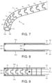
- FIGURE 7 illustrates an implementation of this feature using the embodiment of FIGURE 4 .
- the ends of cables 42-42' are anchored by attachment to the distal link (leftmost) of the bending neck 10 as shown by anchor points 32 and 34 in FIGURE 8 .
- the inner tube 10b has been removed for clarity of illustration.
- the ends of the other set 40-40' of cables are anchored to link 11', the first link following those with pivot lobes 24, as shown by anchor points 36 and 38.
- FIGURE 7 illustrates an implementation in which pivot lobes 14 are formed in the front and back sides of the tube and hence their pivot axes are all normal to the plane of the drawing.
- the pivot lobes 24 of the proximal section of the bending neck are formed on the top and bottom of the tube and have their pivot axes parallel to the plane of the drawing.
- distal section with pivot lobes 14 can be curved in the plane of the drawing whereas the proximal section of links can be curved orthogonally into and out of the drawing plane.
- Cables 42 and 42' extend through cable passageways 12 and are anchored at the ends at anchor points 32 and 34. These cables control the articulation of the distal (leftmost) section of the bending neck.
- the control cables 40 and 40' for the proximal section of the bending neck are oriented 90° around the circumference of the tube from cables 42 and 42'. These control cables must pass through their own, differently positioned control cable passageways oriented 90° relative to passageways 12.
- control cables 40 and 40' are anchored at the distal end of the section of links they control as shown by cable 40 anchored at anchor point 36 in the cutaway view of FIGURE 9 . (Cable 40' and its anchor point are cut away in this view.) When cables 42-42' are pulled the distal section of links is articulated or locked, and when cables 40-40' are pulled the proximal section of links is controlled.
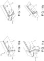
- FIGURES 10a-10b are perspective views of an articulating ultrasound probe of the present invention.
- This probe has two straight, non-articulating sections 60 and 62 and two articulating sections 70 and 72.
- the articulating sections 70 and 72 articulate in the same plane, the horizontal plane H of the drawings.
- the short articulating section 70 is curved by control of its cables anchored at the distal end of section 70.
- the cable set anchored at the distal end of section 72 has been used to articulate section 72. Since all articulation is in the same plane, the pivot lobes of both sections are on the same sides of the section, and only a single pair of cable passageways is necessary for the control cables of both sections.
- FIGURES 11a-11b are perspective views of another articulating ultrasound probe of the present invention, this one implementing articulation in two planes as in the case of FIGURE 9 .
- the articulating section 72 of FIGURE 11a has its pivot lobes, pivot axes, and control cable passageways oriented 90° around the circumference of the tube as compared with those of articulating section 70.
- the distal section 72 can be controllably articulated up and down in the vertical (V) direction.
- pivot lobes may be formed in other shapes and sizes, and pivoting between links can be provided by other, more complicated pin or rivet configurations.
- the implementations illustrated herein have the advantage of being wholly formed from a single or concentric pair of tubes. Instead of sections of identically oriented links, an articulating section can be interspersed with links pivoting at 90° with respect to each other, giving an articulating section the ability to be curved in almost any direction.
Landscapes
- Health & Medical Sciences (AREA)
- Life Sciences & Earth Sciences (AREA)
- Surgery (AREA)
- Engineering & Computer Science (AREA)
- General Health & Medical Sciences (AREA)
- Biophysics (AREA)
- Veterinary Medicine (AREA)
- Biomedical Technology (AREA)
- Heart & Thoracic Surgery (AREA)
- Public Health (AREA)
- Animal Behavior & Ethology (AREA)
- Radiology & Medical Imaging (AREA)
- Molecular Biology (AREA)
- Medical Informatics (AREA)
- Physics & Mathematics (AREA)
- Nuclear Medicine, Radiotherapy & Molecular Imaging (AREA)
- Pathology (AREA)
- Optics & Photonics (AREA)
- Pulmonology (AREA)
- Anesthesiology (AREA)
- Hematology (AREA)
- Manufacturing & Machinery (AREA)
- Rehabilitation Therapy (AREA)
- Mechanical Engineering (AREA)
- Endoscopes (AREA)
- Ultra Sonic Daignosis Equipment (AREA)
- Instruments For Viewing The Inside Of Hollow Bodies (AREA)
Priority Applications (1)
| Application Number | Priority Date | Filing Date | Title |
|---|---|---|---|
| EP24179860.2A EP4417141A3 (en) | 2015-03-02 | 2016-02-23 | Single piece bending neck for an articulating ultrasound probe |
Applications Claiming Priority (2)
| Application Number | Priority Date | Filing Date | Title |
|---|---|---|---|
| US201562126752P | 2015-03-02 | 2015-03-02 | |
| PCT/IB2016/050952 WO2016139550A1 (en) | 2015-03-02 | 2016-02-23 | Single piece bending neck for an articulating ultrasound probe |
Related Child Applications (2)
| Application Number | Title | Priority Date | Filing Date |
|---|---|---|---|
| EP24179860.2A Division EP4417141A3 (en) | 2015-03-02 | 2016-02-23 | Single piece bending neck for an articulating ultrasound probe |
| EP24179860.2A Division-Into EP4417141A3 (en) | 2015-03-02 | 2016-02-23 | Single piece bending neck for an articulating ultrasound probe |
Publications (2)
| Publication Number | Publication Date |
|---|---|
| EP3264968A1 EP3264968A1 (en) | 2018-01-10 |
| EP3264968B1 true EP3264968B1 (en) | 2024-09-25 |
Family
ID=55524401
Family Applications (2)
| Application Number | Title | Priority Date | Filing Date |
|---|---|---|---|
| EP16709591.8A Active EP3264968B1 (en) | 2015-03-02 | 2016-02-23 | Single piece bending neck for an articulating ultrasound probe |
| EP24179860.2A Pending EP4417141A3 (en) | 2015-03-02 | 2016-02-23 | Single piece bending neck for an articulating ultrasound probe |
Family Applications After (1)
| Application Number | Title | Priority Date | Filing Date |
|---|---|---|---|
| EP24179860.2A Pending EP4417141A3 (en) | 2015-03-02 | 2016-02-23 | Single piece bending neck for an articulating ultrasound probe |
Country Status (5)
| Country | Link |
|---|---|
| US (1) | US11707184B2 (enExample) |
| EP (2) | EP3264968B1 (enExample) |
| JP (1) | JP6785783B2 (enExample) |
| CN (1) | CN107405055B (enExample) |
| WO (1) | WO2016139550A1 (enExample) |
Families Citing this family (15)
| Publication number | Priority date | Publication date | Assignee | Title |
|---|---|---|---|---|
| EP3265160B1 (en) * | 2015-03-02 | 2018-12-19 | Koninklijke Philips N.V. | Variable configuration bending neck for an articulating ultrasound probe |
| WO2018165572A1 (en) * | 2017-03-10 | 2018-09-13 | Georgia Tech Research Corporation | Systems and methods for steering guidewires |
| US10918268B2 (en) * | 2017-08-29 | 2021-02-16 | Opcom Inc. | Insert tube and endoscope using the same |
| CN108553070B (zh) * | 2018-05-17 | 2020-09-18 | 黄琴 | 可控弯曲管结构 |
| GB2575675A (en) | 2018-07-19 | 2020-01-22 | Imperial College Sci Tech & Medicine | A device |
| WO2020070851A1 (ja) * | 2018-10-04 | 2020-04-09 | オリンパス株式会社 | 内視鏡湾曲部 |
| US11213309B2 (en) * | 2019-05-23 | 2022-01-04 | Biosense Webster (Israel) Ltd. | Medical probe having improved maneuverability |
| WO2021026019A1 (en) | 2019-08-02 | 2021-02-11 | Raj Subramaniam | Steerable sheath |
| USD1039141S1 (en) | 2020-04-27 | 2024-08-13 | Acclarent, Inc. | Flex section in shaft for ENT instrument |
| CN113967032B (zh) * | 2020-07-24 | 2025-03-04 | 深圳迈瑞生物医疗电子股份有限公司 | 超声设备的浮动装置及超声设备 |
| CN113559395B (zh) * | 2021-07-27 | 2023-04-25 | 西藏自治区人民政府驻成都办事处医院 | 一种brto专用球囊导管及使用方法 |
| CN115054805B (zh) * | 2022-07-05 | 2025-07-25 | 深圳市库珀科技发展有限公司 | 可弯曲导引鞘管及导引装置 |
| EP4302677A1 (en) * | 2022-07-08 | 2024-01-10 | Ambu A/S | A bending section for an endoscope |
| CN117083023A (zh) * | 2023-02-03 | 2023-11-17 | 广州巧捷力医疗机器人有限公司 | 制造外科手术中用于内窥镜的可操纵外科手术臂的方法 |
| WO2024196636A1 (en) * | 2023-03-17 | 2024-09-26 | Boston Scientific Scimed, Inc. | Medical devices and articulation joints for medical devices |
Citations (11)
| Publication number | Priority date | Publication date | Assignee | Title |
|---|---|---|---|---|
| JP3818693B2 (ja) * | 1996-04-22 | 2006-09-06 | オリンパス株式会社 | 内視鏡用湾曲管 |
| US20070049800A1 (en) * | 2005-08-30 | 2007-03-01 | Boston Scientific Scimed, Inc. | Method for forming an endoscope articulation joint |
| WO2008146510A1 (ja) * | 2007-05-31 | 2008-12-04 | Olympus Corporation | 内視鏡の湾曲管、内視鏡、および、内視鏡の湾曲管の製造方法 |
| US20090234191A1 (en) * | 2006-05-17 | 2009-09-17 | Hideya Kitagawa | Bending Part Coupling Assembly for the Endoscope Insertion Portion and Manufacturing Method Thereof |
| US20100287755A1 (en) * | 2009-04-09 | 2010-11-18 | Richard Wolf Gmbh | Method for manufacturing a bendable tube |
| US20100312056A1 (en) * | 2009-06-03 | 2010-12-09 | Gyrus, ACMI, Inc. | Endoscope shaft |
| US20110230718A1 (en) * | 2009-10-14 | 2011-09-22 | Olympus Medical Systems Corp. | Medical flexible section and insertion section of medical apparatus |
| US20120116163A1 (en) * | 2009-05-29 | 2012-05-10 | Aesculap Ag | Control device |
| US20130190561A1 (en) * | 2012-01-10 | 2013-07-25 | Boston Scientific Scimed, Inc. | Steerable medical device having an imaging system |
| US20140053940A1 (en) * | 2012-08-24 | 2014-02-27 | Olympus Medical Systems Corp. | Curved pipe for endoscopes |
| US20140180009A1 (en) * | 2011-12-06 | 2014-06-26 | Olympus Medical Systems Corp. | Bending portion and endoscope |
Family Cites Families (23)
| Publication number | Priority date | Publication date | Assignee | Title |
|---|---|---|---|---|
| DE3829603A1 (de) * | 1988-09-01 | 1990-03-15 | Kontron Holding Ag | Ultraschallendoskopeinrichtung |
| JP3143166B2 (ja) | 1991-10-22 | 2001-03-07 | オリンパス光学工業株式会社 | 内視鏡 |
| US6887235B2 (en) * | 1999-03-24 | 2005-05-03 | Micrus Corporation | Variable stiffness heating catheter |
| JP2002177199A (ja) * | 2000-10-02 | 2002-06-25 | Olympus Optical Co Ltd | 内視鏡 |
| US7250027B2 (en) * | 2002-05-30 | 2007-07-31 | Karl Storz Endovision, Inc. | Articulating vertebrae with asymmetrical and variable radius of curvature |
| JP2004105289A (ja) * | 2002-09-13 | 2004-04-08 | Olympus Corp | 超音波内視鏡 |
| US7410483B2 (en) | 2003-05-23 | 2008-08-12 | Novare Surgical Systems, Inc. | Hand-actuated device for remote manipulation of a grasping tool |
| JP2005040293A (ja) * | 2003-07-28 | 2005-02-17 | Olympus Corp | 内視鏡 |
| JP2007502671A (ja) | 2003-08-20 | 2007-02-15 | ネオガイド システムズ, インコーポレイテッド | 活性ポリマー関節運動器具及び挿入方法 |
| WO2005113057A1 (en) * | 2004-05-17 | 2005-12-01 | C. R. Bard, Inc. | Articulated catheter |
| JP2005334050A (ja) * | 2004-05-24 | 2005-12-08 | Fujinon Corp | 内視鏡のアングル部 |
| DE102004027850A1 (de) | 2004-06-08 | 2006-01-05 | Henke-Sass Wolf Gmbh | Biegbarer Abschnitt eines Einführtubus eines Endoskopes und Verfahren zu dessen Herstellung |
| JP4477519B2 (ja) | 2005-02-14 | 2010-06-09 | オリンパス株式会社 | 内視鏡 |
| JP2007236751A (ja) * | 2006-03-10 | 2007-09-20 | Olympus Corp | 内視鏡挿入部 |
| JP2009528910A (ja) | 2006-03-06 | 2009-08-13 | イマコー・エルエルシー | 調整可能な曲げセクションを有する経食道超音波プローブ |
| JP2008259634A (ja) * | 2007-04-11 | 2008-10-30 | Olympus Corp | 内視鏡用可撓管と環状連結部材との連結構造 |
| WO2009062150A1 (en) | 2007-11-11 | 2009-05-14 | Imacor Llc | Transesophageal ultrasound probe with an adaptive bending section |
| JP5404154B2 (ja) | 2009-04-21 | 2014-01-29 | オリンパス株式会社 | 内視鏡湾曲部及び湾曲管の製造方法 |
| US9254123B2 (en) | 2009-04-29 | 2016-02-09 | Hansen Medical, Inc. | Flexible and steerable elongate instruments with shape control and support elements |
| JP2011067423A (ja) * | 2009-09-25 | 2011-04-07 | Olympus Corp | 内視鏡挿入部及びその製造方法 |
| US9474540B2 (en) * | 2009-10-08 | 2016-10-25 | Ethicon-Endo-Surgery, Inc. | Laparoscopic device with compound angulation |
| JP6082237B2 (ja) | 2011-12-09 | 2017-02-15 | 株式会社トクヤマ | テクスチャー構造を有するシリコン基板の製法 |
| CN107666873B (zh) | 2014-12-05 | 2020-07-17 | 微创手术医疗器械公司 | 用于制造可操纵仪器的方法和这种可操纵仪器 |
-
2016
- 2016-02-23 WO PCT/IB2016/050952 patent/WO2016139550A1/en not_active Ceased
- 2016-02-23 EP EP16709591.8A patent/EP3264968B1/en active Active
- 2016-02-23 US US15/552,319 patent/US11707184B2/en active Active
- 2016-02-23 JP JP2017544963A patent/JP6785783B2/ja active Active
- 2016-02-23 EP EP24179860.2A patent/EP4417141A3/en active Pending
- 2016-02-23 CN CN201680013261.4A patent/CN107405055B/zh active Active
Patent Citations (11)
| Publication number | Priority date | Publication date | Assignee | Title |
|---|---|---|---|---|
| JP3818693B2 (ja) * | 1996-04-22 | 2006-09-06 | オリンパス株式会社 | 内視鏡用湾曲管 |
| US20070049800A1 (en) * | 2005-08-30 | 2007-03-01 | Boston Scientific Scimed, Inc. | Method for forming an endoscope articulation joint |
| US20090234191A1 (en) * | 2006-05-17 | 2009-09-17 | Hideya Kitagawa | Bending Part Coupling Assembly for the Endoscope Insertion Portion and Manufacturing Method Thereof |
| WO2008146510A1 (ja) * | 2007-05-31 | 2008-12-04 | Olympus Corporation | 内視鏡の湾曲管、内視鏡、および、内視鏡の湾曲管の製造方法 |
| US20100287755A1 (en) * | 2009-04-09 | 2010-11-18 | Richard Wolf Gmbh | Method for manufacturing a bendable tube |
| US20120116163A1 (en) * | 2009-05-29 | 2012-05-10 | Aesculap Ag | Control device |
| US20100312056A1 (en) * | 2009-06-03 | 2010-12-09 | Gyrus, ACMI, Inc. | Endoscope shaft |
| US20110230718A1 (en) * | 2009-10-14 | 2011-09-22 | Olympus Medical Systems Corp. | Medical flexible section and insertion section of medical apparatus |
| US20140180009A1 (en) * | 2011-12-06 | 2014-06-26 | Olympus Medical Systems Corp. | Bending portion and endoscope |
| US20130190561A1 (en) * | 2012-01-10 | 2013-07-25 | Boston Scientific Scimed, Inc. | Steerable medical device having an imaging system |
| US20140053940A1 (en) * | 2012-08-24 | 2014-02-27 | Olympus Medical Systems Corp. | Curved pipe for endoscopes |
Also Published As
| Publication number | Publication date |
|---|---|
| WO2016139550A1 (en) | 2016-09-09 |
| US11707184B2 (en) | 2023-07-25 |
| CN107405055A (zh) | 2017-11-28 |
| CN107405055B (zh) | 2020-08-28 |
| JP6785783B2 (ja) | 2020-11-18 |
| EP4417141A3 (en) | 2024-12-18 |
| EP4417141A2 (en) | 2024-08-21 |
| EP3264968A1 (en) | 2018-01-10 |
| JP2018507053A (ja) | 2018-03-15 |
| US20180042451A1 (en) | 2018-02-15 |
Similar Documents
| Publication | Publication Date | Title |
|---|---|---|
| EP3264968B1 (en) | Single piece bending neck for an articulating ultrasound probe | |
| US11452501B2 (en) | Variable configuration bending neck for an articulating ultrasound probe | |
| EP2874532B1 (en) | Elongate medical device with articulating portion | |
| CA3077490C (en) | Method for manufacturing an endoscope insertion tube, and endoscope having an insertion tube | |
| JP7692348B2 (ja) | ジョイント | |
| US8333417B2 (en) | Manipulator tool and holding and/or expanding tool with at least one manipulator tool | |
| JP7682514B2 (ja) | 内視鏡手術で使用する操縦可能なアーム | |
| CN101938933B (zh) | 可操纵管 | |
| GB2456165A (en) | Slotted, flexible shaft for an endoscopic instrument | |
| JP2012527918A (ja) | 外科用器具 | |
| JP2024019439A (ja) | パターン化されたチューブ |
Legal Events
| Date | Code | Title | Description |
|---|---|---|---|
| STAA | Information on the status of an ep patent application or granted ep patent |
Free format text: STATUS: THE INTERNATIONAL PUBLICATION HAS BEEN MADE |
|
| PUAI | Public reference made under article 153(3) epc to a published international application that has entered the european phase |
Free format text: ORIGINAL CODE: 0009012 |
|
| STAA | Information on the status of an ep patent application or granted ep patent |
Free format text: STATUS: REQUEST FOR EXAMINATION WAS MADE |
|
| 17P | Request for examination filed |
Effective date: 20171002 |
|
| AK | Designated contracting states |
Kind code of ref document: A1 Designated state(s): AL AT BE BG CH CY CZ DE DK EE ES FI FR GB GR HR HU IE IS IT LI LT LU LV MC MK MT NL NO PL PT RO RS SE SI SK SM TR |
|
| AX | Request for extension of the european patent |
Extension state: BA ME |
|
| DAV | Request for validation of the european patent (deleted) | ||
| DAX | Request for extension of the european patent (deleted) | ||
| PUAG | Search results despatched under rule 164(2) epc together with communication from examining division |
Free format text: ORIGINAL CODE: 0009017 |
|
| STAA | Information on the status of an ep patent application or granted ep patent |
Free format text: STATUS: EXAMINATION IS IN PROGRESS |
|
| 17Q | First examination report despatched |
Effective date: 20181015 |
|
| B565 | Issuance of search results under rule 164(2) epc |
Effective date: 20181015 |
|
| RIC1 | Information provided on ipc code assigned before grant |
Ipc: A61B 1/008 20060101ALI20181010BHEP Ipc: A61B 1/00 20060101ALI20181010BHEP Ipc: A61B 8/12 20060101ALI20181010BHEP Ipc: A61M 25/01 20060101ALI20181010BHEP Ipc: A61B 1/005 20060101AFI20181010BHEP Ipc: A61B 17/00 20060101ALI20181010BHEP |
|
| RAP1 | Party data changed (applicant data changed or rights of an application transferred) |
Owner name: KONINKLIJKE PHILIPS N.V. |
|
| GRAP | Despatch of communication of intention to grant a patent |
Free format text: ORIGINAL CODE: EPIDOSNIGR1 |
|
| STAA | Information on the status of an ep patent application or granted ep patent |
Free format text: STATUS: GRANT OF PATENT IS INTENDED |
|
| INTG | Intention to grant announced |
Effective date: 20240425 |
|
| GRAS | Grant fee paid |
Free format text: ORIGINAL CODE: EPIDOSNIGR3 |
|
| GRAA | (expected) grant |
Free format text: ORIGINAL CODE: 0009210 |
|
| STAA | Information on the status of an ep patent application or granted ep patent |
Free format text: STATUS: THE PATENT HAS BEEN GRANTED |
|
| AK | Designated contracting states |
Kind code of ref document: B1 Designated state(s): AL AT BE BG CH CY CZ DE DK EE ES FI FR GB GR HR HU IE IS IT LI LT LU LV MC MK MT NL NO PL PT RO RS SE SI SK SM TR |
|
| REG | Reference to a national code |
Ref country code: GB Ref legal event code: FG4D |
|
| REG | Reference to a national code |
Ref country code: CH Ref legal event code: EP |
|
| REG | Reference to a national code |
Ref country code: DE Ref legal event code: R096 Ref document number: 602016089527 Country of ref document: DE |
|
| REG | Reference to a national code |
Ref country code: IE Ref legal event code: FG4D |
|
| REG | Reference to a national code |
Ref country code: DE Ref legal event code: R084 Ref document number: 602016089527 Country of ref document: DE |
|
| REG | Reference to a national code |
Ref country code: LT Ref legal event code: MG9D |
|
| PG25 | Lapsed in a contracting state [announced via postgrant information from national office to epo] |
Ref country code: NO Free format text: LAPSE BECAUSE OF FAILURE TO SUBMIT A TRANSLATION OF THE DESCRIPTION OR TO PAY THE FEE WITHIN THE PRESCRIBED TIME-LIMIT Effective date: 20241225 |
|
| PG25 | Lapsed in a contracting state [announced via postgrant information from national office to epo] |
Ref country code: GR Free format text: LAPSE BECAUSE OF FAILURE TO SUBMIT A TRANSLATION OF THE DESCRIPTION OR TO PAY THE FEE WITHIN THE PRESCRIBED TIME-LIMIT Effective date: 20241226 Ref country code: FI Free format text: LAPSE BECAUSE OF FAILURE TO SUBMIT A TRANSLATION OF THE DESCRIPTION OR TO PAY THE FEE WITHIN THE PRESCRIBED TIME-LIMIT Effective date: 20240925 |
|
| PG25 | Lapsed in a contracting state [announced via postgrant information from national office to epo] |
Ref country code: BG Free format text: LAPSE BECAUSE OF FAILURE TO SUBMIT A TRANSLATION OF THE DESCRIPTION OR TO PAY THE FEE WITHIN THE PRESCRIBED TIME-LIMIT Effective date: 20240925 |
|
| PG25 | Lapsed in a contracting state [announced via postgrant information from national office to epo] |
Ref country code: LV Free format text: LAPSE BECAUSE OF FAILURE TO SUBMIT A TRANSLATION OF THE DESCRIPTION OR TO PAY THE FEE WITHIN THE PRESCRIBED TIME-LIMIT Effective date: 20240925 |
|
| PG25 | Lapsed in a contracting state [announced via postgrant information from national office to epo] |
Ref country code: RS Free format text: LAPSE BECAUSE OF FAILURE TO SUBMIT A TRANSLATION OF THE DESCRIPTION OR TO PAY THE FEE WITHIN THE PRESCRIBED TIME-LIMIT Effective date: 20241225 |
|
| REG | Reference to a national code |
Ref country code: NL Ref legal event code: MP Effective date: 20240925 |
|
| PG25 | Lapsed in a contracting state [announced via postgrant information from national office to epo] |
Ref country code: RS Free format text: LAPSE BECAUSE OF FAILURE TO SUBMIT A TRANSLATION OF THE DESCRIPTION OR TO PAY THE FEE WITHIN THE PRESCRIBED TIME-LIMIT Effective date: 20241225 Ref country code: NO Free format text: LAPSE BECAUSE OF FAILURE TO SUBMIT A TRANSLATION OF THE DESCRIPTION OR TO PAY THE FEE WITHIN THE PRESCRIBED TIME-LIMIT Effective date: 20241225 Ref country code: LV Free format text: LAPSE BECAUSE OF FAILURE TO SUBMIT A TRANSLATION OF THE DESCRIPTION OR TO PAY THE FEE WITHIN THE PRESCRIBED TIME-LIMIT Effective date: 20240925 Ref country code: GR Free format text: LAPSE BECAUSE OF FAILURE TO SUBMIT A TRANSLATION OF THE DESCRIPTION OR TO PAY THE FEE WITHIN THE PRESCRIBED TIME-LIMIT Effective date: 20241226 Ref country code: FI Free format text: LAPSE BECAUSE OF FAILURE TO SUBMIT A TRANSLATION OF THE DESCRIPTION OR TO PAY THE FEE WITHIN THE PRESCRIBED TIME-LIMIT Effective date: 20240925 Ref country code: BG Free format text: LAPSE BECAUSE OF FAILURE TO SUBMIT A TRANSLATION OF THE DESCRIPTION OR TO PAY THE FEE WITHIN THE PRESCRIBED TIME-LIMIT Effective date: 20240925 |
|
| REG | Reference to a national code |
Ref country code: AT Ref legal event code: MK05 Ref document number: 1725928 Country of ref document: AT Kind code of ref document: T Effective date: 20240925 |
|
| PG25 | Lapsed in a contracting state [announced via postgrant information from national office to epo] |
Ref country code: NL Free format text: LAPSE BECAUSE OF FAILURE TO SUBMIT A TRANSLATION OF THE DESCRIPTION OR TO PAY THE FEE WITHIN THE PRESCRIBED TIME-LIMIT Effective date: 20240925 |
|
| PG25 | Lapsed in a contracting state [announced via postgrant information from national office to epo] |
Ref country code: IS Free format text: LAPSE BECAUSE OF FAILURE TO SUBMIT A TRANSLATION OF THE DESCRIPTION OR TO PAY THE FEE WITHIN THE PRESCRIBED TIME-LIMIT Effective date: 20250125 Ref country code: PT Free format text: LAPSE BECAUSE OF FAILURE TO SUBMIT A TRANSLATION OF THE DESCRIPTION OR TO PAY THE FEE WITHIN THE PRESCRIBED TIME-LIMIT Effective date: 20250127 |
|
| PGFP | Annual fee paid to national office [announced via postgrant information from national office to epo] |
Ref country code: DE Payment date: 20250226 Year of fee payment: 10 |
|
| PG25 | Lapsed in a contracting state [announced via postgrant information from national office to epo] |
Ref country code: RO Free format text: LAPSE BECAUSE OF FAILURE TO SUBMIT A TRANSLATION OF THE DESCRIPTION OR TO PAY THE FEE WITHIN THE PRESCRIBED TIME-LIMIT Effective date: 20240925 Ref country code: SM Free format text: LAPSE BECAUSE OF FAILURE TO SUBMIT A TRANSLATION OF THE DESCRIPTION OR TO PAY THE FEE WITHIN THE PRESCRIBED TIME-LIMIT Effective date: 20240925 |
|
| PG25 | Lapsed in a contracting state [announced via postgrant information from national office to epo] |
Ref country code: ES Free format text: LAPSE BECAUSE OF FAILURE TO SUBMIT A TRANSLATION OF THE DESCRIPTION OR TO PAY THE FEE WITHIN THE PRESCRIBED TIME-LIMIT Effective date: 20240925 |
|
| PG25 | Lapsed in a contracting state [announced via postgrant information from national office to epo] |
Ref country code: EE Free format text: LAPSE BECAUSE OF FAILURE TO SUBMIT A TRANSLATION OF THE DESCRIPTION OR TO PAY THE FEE WITHIN THE PRESCRIBED TIME-LIMIT Effective date: 20240925 Ref country code: AT Free format text: LAPSE BECAUSE OF FAILURE TO SUBMIT A TRANSLATION OF THE DESCRIPTION OR TO PAY THE FEE WITHIN THE PRESCRIBED TIME-LIMIT Effective date: 20240925 |
|
| PG25 | Lapsed in a contracting state [announced via postgrant information from national office to epo] |
Ref country code: CZ Free format text: LAPSE BECAUSE OF FAILURE TO SUBMIT A TRANSLATION OF THE DESCRIPTION OR TO PAY THE FEE WITHIN THE PRESCRIBED TIME-LIMIT Effective date: 20240925 Ref country code: PL Free format text: LAPSE BECAUSE OF FAILURE TO SUBMIT A TRANSLATION OF THE DESCRIPTION OR TO PAY THE FEE WITHIN THE PRESCRIBED TIME-LIMIT Effective date: 20240925 |
|
| PG25 | Lapsed in a contracting state [announced via postgrant information from national office to epo] |
Ref country code: IT Free format text: LAPSE BECAUSE OF FAILURE TO SUBMIT A TRANSLATION OF THE DESCRIPTION OR TO PAY THE FEE WITHIN THE PRESCRIBED TIME-LIMIT Effective date: 20240925 Ref country code: SK Free format text: LAPSE BECAUSE OF FAILURE TO SUBMIT A TRANSLATION OF THE DESCRIPTION OR TO PAY THE FEE WITHIN THE PRESCRIBED TIME-LIMIT Effective date: 20240925 |
|
| PGFP | Annual fee paid to national office [announced via postgrant information from national office to epo] |
Ref country code: GB Payment date: 20250218 Year of fee payment: 10 |
|
| REG | Reference to a national code |
Ref country code: DE Ref legal event code: R097 Ref document number: 602016089527 Country of ref document: DE |
|
| PG25 | Lapsed in a contracting state [announced via postgrant information from national office to epo] |
Ref country code: DK Free format text: LAPSE BECAUSE OF FAILURE TO SUBMIT A TRANSLATION OF THE DESCRIPTION OR TO PAY THE FEE WITHIN THE PRESCRIBED TIME-LIMIT Effective date: 20240925 |
|
| PLBE | No opposition filed within time limit |
Free format text: ORIGINAL CODE: 0009261 |
|
| STAA | Information on the status of an ep patent application or granted ep patent |
Free format text: STATUS: NO OPPOSITION FILED WITHIN TIME LIMIT |
|
| 26N | No opposition filed |
Effective date: 20250626 |
|
| PG25 | Lapsed in a contracting state [announced via postgrant information from national office to epo] |
Ref country code: SE Free format text: LAPSE BECAUSE OF FAILURE TO SUBMIT A TRANSLATION OF THE DESCRIPTION OR TO PAY THE FEE WITHIN THE PRESCRIBED TIME-LIMIT Effective date: 20240925 |
|
| PG25 | Lapsed in a contracting state [announced via postgrant information from national office to epo] |
Ref country code: MC Free format text: LAPSE BECAUSE OF FAILURE TO SUBMIT A TRANSLATION OF THE DESCRIPTION OR TO PAY THE FEE WITHIN THE PRESCRIBED TIME-LIMIT Effective date: 20240925 |
|
| REG | Reference to a national code |
Ref country code: CH Ref legal event code: PL |
|
| PG25 | Lapsed in a contracting state [announced via postgrant information from national office to epo] |
Ref country code: LU Free format text: LAPSE BECAUSE OF NON-PAYMENT OF DUE FEES Effective date: 20250223 |
|
| PG25 | Lapsed in a contracting state [announced via postgrant information from national office to epo] |
Ref country code: CH Free format text: LAPSE BECAUSE OF NON-PAYMENT OF DUE FEES Effective date: 20250228 |
|
| REG | Reference to a national code |
Ref country code: BE Ref legal event code: MM Effective date: 20250228 |