EP3263168A1 - Medizinische vorrichtungen mit inneren und äusseren kanülen - Google Patents
Medizinische vorrichtungen mit inneren und äusseren kanülen Download PDFInfo
- Publication number
- EP3263168A1 EP3263168A1 EP17178169.3A EP17178169A EP3263168A1 EP 3263168 A1 EP3263168 A1 EP 3263168A1 EP 17178169 A EP17178169 A EP 17178169A EP 3263168 A1 EP3263168 A1 EP 3263168A1
- Authority
- EP
- European Patent Office
- Prior art keywords
- cannula
- outer cannula
- side port
- medical device
- inner cannula
- Prior art date
- Legal status (The legal status is an assumption and is not a legal conclusion. Google has not performed a legal analysis and makes no representation as to the accuracy of the status listed.)
- Granted
Links
- 239000000463 material Substances 0.000 claims description 37
- 229910052751 metal Inorganic materials 0.000 claims description 9
- 239000002184 metal Substances 0.000 claims description 9
- 229910045601 alloy Inorganic materials 0.000 claims description 4
- 239000000956 alloy Substances 0.000 claims description 4
- 239000010935 stainless steel Substances 0.000 claims description 4
- 229910001220 stainless steel Inorganic materials 0.000 claims description 4
- 238000005219 brazing Methods 0.000 claims description 3
- 229910000679 solder Inorganic materials 0.000 claims description 2
- 238000005452 bending Methods 0.000 claims 1
- 230000004323 axial length Effects 0.000 description 32
- 238000000034 method Methods 0.000 description 9
- 239000000853 adhesive Substances 0.000 description 6
- 230000001070 adhesive effect Effects 0.000 description 6
- 239000011248 coating agent Substances 0.000 description 4
- 238000000576 coating method Methods 0.000 description 4
- 239000012530 fluid Substances 0.000 description 4
- 238000004519 manufacturing process Methods 0.000 description 4
- 150000002739 metals Chemical class 0.000 description 3
- 229910001000 nickel titanium Inorganic materials 0.000 description 3
- 229920000139 polyethylene terephthalate Polymers 0.000 description 3
- 239000005020 polyethylene terephthalate Substances 0.000 description 3
- 230000007704 transition Effects 0.000 description 3
- 229910000684 Cobalt-chrome Inorganic materials 0.000 description 2
- 239000010952 cobalt-chrome Substances 0.000 description 2
- 238000004891 communication Methods 0.000 description 2
- 238000002788 crimping Methods 0.000 description 2
- 230000006378 damage Effects 0.000 description 2
- 230000004927 fusion Effects 0.000 description 2
- 239000000203 mixture Substances 0.000 description 2
- 230000000750 progressive effect Effects 0.000 description 2
- 239000004677 Nylon Substances 0.000 description 1
- 239000004952 Polyamide Substances 0.000 description 1
- HZEWFHLRYVTOIW-UHFFFAOYSA-N [Ti].[Ni] Chemical compound [Ti].[Ni] HZEWFHLRYVTOIW-UHFFFAOYSA-N 0.000 description 1
- 239000008280 blood Substances 0.000 description 1
- 210000004369 blood Anatomy 0.000 description 1
- 210000001124 body fluid Anatomy 0.000 description 1
- 239000010839 body fluid Substances 0.000 description 1
- 230000018109 developmental process Effects 0.000 description 1
- 230000006870 function Effects 0.000 description 1
- 230000001788 irregular Effects 0.000 description 1
- 238000005304 joining Methods 0.000 description 1
- 238000003698 laser cutting Methods 0.000 description 1
- HLXZNVUGXRDIFK-UHFFFAOYSA-N nickel titanium Chemical compound [Ti].[Ti].[Ti].[Ti].[Ti].[Ti].[Ti].[Ti].[Ti].[Ti].[Ti].[Ni].[Ni].[Ni].[Ni].[Ni].[Ni].[Ni].[Ni].[Ni].[Ni].[Ni].[Ni].[Ni].[Ni] HLXZNVUGXRDIFK-UHFFFAOYSA-N 0.000 description 1
- 229920001778 nylon Polymers 0.000 description 1
- 239000004033 plastic Substances 0.000 description 1
- 229920003023 plastic Polymers 0.000 description 1
- 229920002647 polyamide Polymers 0.000 description 1
- -1 polyethylene terephthalate Polymers 0.000 description 1
- 238000007789 sealing Methods 0.000 description 1
- 238000004513 sizing Methods 0.000 description 1
- 239000000126 substance Substances 0.000 description 1
- 238000003466 welding Methods 0.000 description 1
Images


Classifications
-
- A—HUMAN NECESSITIES
- A61—MEDICAL OR VETERINARY SCIENCE; HYGIENE
- A61B—DIAGNOSIS; SURGERY; IDENTIFICATION
- A61B17/00—Surgical instruments, devices or methods, e.g. tourniquets
- A61B17/34—Trocars; Puncturing needles
- A61B17/3417—Details of tips or shafts, e.g. grooves, expandable, bendable; Multiple coaxial sliding cannulas, e.g. for dilating
- A61B17/3421—Cannulas
- A61B17/3439—Cannulas with means for changing the inner diameter of the cannula, e.g. expandable
-
- A—HUMAN NECESSITIES
- A61—MEDICAL OR VETERINARY SCIENCE; HYGIENE
- A61B—DIAGNOSIS; SURGERY; IDENTIFICATION
- A61B17/00—Surgical instruments, devices or methods, e.g. tourniquets
- A61B17/34—Trocars; Puncturing needles
- A61B17/3462—Trocars; Puncturing needles with means for changing the diameter or the orientation of the entrance port of the cannula, e.g. for use with different-sized instruments, reduction ports, adapter seals
-
- A—HUMAN NECESSITIES
- A61—MEDICAL OR VETERINARY SCIENCE; HYGIENE
- A61B—DIAGNOSIS; SURGERY; IDENTIFICATION
- A61B5/00—Measuring for diagnostic purposes; Identification of persons
-
- A—HUMAN NECESSITIES
- A61—MEDICAL OR VETERINARY SCIENCE; HYGIENE
- A61M—DEVICES FOR INTRODUCING MEDIA INTO, OR ONTO, THE BODY; DEVICES FOR TRANSDUCING BODY MEDIA OR FOR TAKING MEDIA FROM THE BODY; DEVICES FOR PRODUCING OR ENDING SLEEP OR STUPOR
- A61M25/00—Catheters; Hollow probes
- A61M25/0043—Catheters; Hollow probes characterised by structural features
- A61M25/0045—Catheters; Hollow probes characterised by structural features multi-layered, e.g. coated
-
- A—HUMAN NECESSITIES
- A61—MEDICAL OR VETERINARY SCIENCE; HYGIENE
- A61M—DEVICES FOR INTRODUCING MEDIA INTO, OR ONTO, THE BODY; DEVICES FOR TRANSDUCING BODY MEDIA OR FOR TAKING MEDIA FROM THE BODY; DEVICES FOR PRODUCING OR ENDING SLEEP OR STUPOR
- A61M25/00—Catheters; Hollow probes
- A61M25/0043—Catheters; Hollow probes characterised by structural features
- A61M25/0054—Catheters; Hollow probes characterised by structural features with regions for increasing flexibility
-
- A—HUMAN NECESSITIES
- A61—MEDICAL OR VETERINARY SCIENCE; HYGIENE
- A61M—DEVICES FOR INTRODUCING MEDIA INTO, OR ONTO, THE BODY; DEVICES FOR TRANSDUCING BODY MEDIA OR FOR TAKING MEDIA FROM THE BODY; DEVICES FOR PRODUCING OR ENDING SLEEP OR STUPOR
- A61M25/00—Catheters; Hollow probes
- A61M25/0067—Catheters; Hollow probes characterised by the distal end, e.g. tips
- A61M25/0068—Static characteristics of the catheter tip, e.g. shape, atraumatic tip, curved tip or tip structure
- A61M25/007—Side holes, e.g. their profiles or arrangements; Provisions to keep side holes unblocked
-
- A—HUMAN NECESSITIES
- A61—MEDICAL OR VETERINARY SCIENCE; HYGIENE
- A61M—DEVICES FOR INTRODUCING MEDIA INTO, OR ONTO, THE BODY; DEVICES FOR TRANSDUCING BODY MEDIA OR FOR TAKING MEDIA FROM THE BODY; DEVICES FOR PRODUCING OR ENDING SLEEP OR STUPOR
- A61M25/00—Catheters; Hollow probes
- A61M25/01—Introducing, guiding, advancing, emplacing or holding catheters
- A61M25/0105—Steering means as part of the catheter or advancing means; Markers for positioning
- A61M25/0133—Tip steering devices
- A61M25/0138—Tip steering devices having flexible regions as a result of weakened outer material, e.g. slots, slits, cuts, joints or coils
-
- A—HUMAN NECESSITIES
- A61—MEDICAL OR VETERINARY SCIENCE; HYGIENE
- A61B—DIAGNOSIS; SURGERY; IDENTIFICATION
- A61B17/00—Surgical instruments, devices or methods, e.g. tourniquets
- A61B17/34—Trocars; Puncturing needles
- A61B17/3417—Details of tips or shafts, e.g. grooves, expandable, bendable; Multiple coaxial sliding cannulas, e.g. for dilating
- A61B17/3421—Cannulas
- A61B2017/3433—Cannulas with different outer diameters of the cannula
-
- A—HUMAN NECESSITIES
- A61—MEDICAL OR VETERINARY SCIENCE; HYGIENE
- A61B—DIAGNOSIS; SURGERY; IDENTIFICATION
- A61B17/00—Surgical instruments, devices or methods, e.g. tourniquets
- A61B17/34—Trocars; Puncturing needles
- A61B17/3417—Details of tips or shafts, e.g. grooves, expandable, bendable; Multiple coaxial sliding cannulas, e.g. for dilating
- A61B17/3421—Cannulas
- A61B2017/3443—Cannulas with means for adjusting the length of a cannula
-
- A—HUMAN NECESSITIES
- A61—MEDICAL OR VETERINARY SCIENCE; HYGIENE
- A61M—DEVICES FOR INTRODUCING MEDIA INTO, OR ONTO, THE BODY; DEVICES FOR TRANSDUCING BODY MEDIA OR FOR TAKING MEDIA FROM THE BODY; DEVICES FOR PRODUCING OR ENDING SLEEP OR STUPOR
- A61M25/00—Catheters; Hollow probes
- A61M2025/0004—Catheters; Hollow probes having two or more concentrically arranged tubes for forming a concentric catheter system
- A61M2025/0006—Catheters; Hollow probes having two or more concentrically arranged tubes for forming a concentric catheter system which can be secured against axial movement, e.g. by using a locking cuff
-
- A—HUMAN NECESSITIES
- A61—MEDICAL OR VETERINARY SCIENCE; HYGIENE
- A61M—DEVICES FOR INTRODUCING MEDIA INTO, OR ONTO, THE BODY; DEVICES FOR TRANSDUCING BODY MEDIA OR FOR TAKING MEDIA FROM THE BODY; DEVICES FOR PRODUCING OR ENDING SLEEP OR STUPOR
- A61M25/00—Catheters; Hollow probes
- A61M25/01—Introducing, guiding, advancing, emplacing or holding catheters
- A61M2025/018—Catheters having a lateral opening for guiding elongated means lateral to the catheter
-
- A—HUMAN NECESSITIES
- A61—MEDICAL OR VETERINARY SCIENCE; HYGIENE
- A61M—DEVICES FOR INTRODUCING MEDIA INTO, OR ONTO, THE BODY; DEVICES FOR TRANSDUCING BODY MEDIA OR FOR TAKING MEDIA FROM THE BODY; DEVICES FOR PRODUCING OR ENDING SLEEP OR STUPOR
- A61M25/00—Catheters; Hollow probes
- A61M25/10—Balloon catheters
- A61M2025/1043—Balloon catheters with special features or adapted for special applications
- A61M2025/1045—Balloon catheters with special features or adapted for special applications for treating bifurcations, e.g. balloons in y-configuration, separate balloons or special features of the catheter for treating bifurcations
-
- A—HUMAN NECESSITIES
- A61—MEDICAL OR VETERINARY SCIENCE; HYGIENE
- A61M—DEVICES FOR INTRODUCING MEDIA INTO, OR ONTO, THE BODY; DEVICES FOR TRANSDUCING BODY MEDIA OR FOR TAKING MEDIA FROM THE BODY; DEVICES FOR PRODUCING OR ENDING SLEEP OR STUPOR
- A61M25/00—Catheters; Hollow probes
- A61M25/0043—Catheters; Hollow probes characterised by structural features
Definitions
- the disclosure relates generally to the field of medical devices. More particularly, the disclosure relates to the fields of medical devices having inner and outer or coaxial cannulae and methods of making medical devices that include such cannulae.
- Medical devices used in the delivery of treatment at a location within a body vessel require both pushability and flexibility. Development of medical devices that provide these desirable characteristics continues.
- An example medical device comprises an inner cannula disposed within and secured to an outer cannula.
- the outer cannula defines a pattern of openings along a portion of the axial length of the outer cannula.
- Another example medical device comprises an outer cannula having a lengthwise axis and an outer cannula circumferential wall extending between an outer cannula proximal end and an outer cannula distal end and defining an outer cannula interior lumen, the outer cannula circumferential wall defining a pattern of openings extending along a spiral path about the lengthwise axis; and an inner cannula disposed within outer cannula interior lumen and secured to the outer cannula, the inner cannula having an inner cannula circumferential wall extending between an inner cannula proximal end and an inner cannula distal end and defining an inner cannula interior lumen.
- Another example medical device comprises an outer cannula having an outer cannula lengthwise axis and an outer cannula circumferential wall extending between an outer cannula proximal end and an outer cannula distal end, the outer cannula circumferential wall defining an outer cannula interior lumen and a first side port opening extending through the outer cannula circumferential wall; an inner cannula disposed within outer cannula interior lumen and secured to the outer cannula, the inner cannula having an inner cannula lengthwise axis, an inner cannula circumferential wall extending between an inner cannula proximal end and an inner cannula distal end, the inner cannula circumferential wall defining an inner cannula interior lumen, a pattern of openings extending along a spiral path about the inner cannula lengthwise axis, and a second side port opening extending through the outer cannula circumferential wall and aligned
- Another example medical device comprises an outer cannula having an outer cannula lengthwise axis and an outer cannula circumferential wall extending between an outer cannula proximal end and an outer cannula distal end, the outer cannula circumferential wall defining an outer cannula interior lumen and a first side port opening extending through the outer cannula circumferential wall, the outer cannula comprising a polymeric material and being free of openings in the outer cannula circumferential wall other than the first side port opening; an inner cannula disposed within outer cannula interior lumen and secured to the outer cannula, the inner cannula having an inner cannula lengthwise axis, an inner cannula circumferential wall extending between an inner cannula proximal end and an inner cannula distal end, the inner cannula circumferential wall defining an inner cannula interior lumen, a pattern of openings extending along a spiral
- An example method of making a medical device comprises passing a first cannula into an interior lumen of a second cannula that defines a pattern of openings extending along a spiral path on its circumferential wall; and securing the first cannula to the second cannula.
- opening refers to a passage defined by a member between opposing or substantially opposing surfaces of the member.
- the term does not require any particular configuration of the passage. Indeed, the term includes rectangular passages, generally rectangular passages, square passages, generally square passages, circular passages, generally circular passages, triangular passages, generally triangular passages, and irregular passages.
- the term "secured to” refers to the state of one object being attached to another object such that each object is substantially incapable of being axially moved relative to the other object.
- the term accommodates a small degree of relative axial movement between the objects, such as a slight amount of relative axial movement that might occur as coaxial cannulae that are secured to each other are bent to form a curve.
- any suitably type of attachment can be used, including fusion joints, such as joints formed by welding the two objects, and non-fusion joints, such as joints formed by brazing the two objects; mechanical attachments, such as attachments formed by swaging the two objects and attachments formed by crimping the two objects; adhesive attachments, such as attachments formed by inclusion of an adhesive material or member disposed between the two objects; friction-based attachments, such as a friction fit in which the relative sizes of the two objects provide a mechanical securement between the objects; combinations of these types of attachments; and any other suitable type of attachment.
- fusion joints such as joints formed by welding the two objects, and non-fusion joints, such as joints formed by brazing the two objects
- mechanical attachments such as attachments formed by swaging the two objects and attachments formed by crimping the two objects
- adhesive attachments such as attachments formed by inclusion of an adhesive material or member disposed between the two objects
- friction-based attachments such as a friction fit in which the relative sizes of the two objects provide a mechanical
- an attachment of any suitable quality can be used, such as a permanent attachment, which requires a degree of destruction of one or both of the objects to remove; a fixed attachment, which requires some manipulation of the attachment to remove; or a temporary attachment, which can be removed simply by manipulating one or both of the objects without imparting a degree of destruction onto either of the objects.
- slit refers to an opening that has a rectangular or generally rectangular shape when the surfaces between which the passage extends lie on parallel planes.
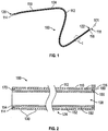
- FIGS. 1, 2 , 4A, 4B, and 5 illustrate a first example medical device 100.
- the medical device 100 includes an inner cannula 150 disposed within and secured to an outer cannula 110 such that the inner 150 and outer 110 cannulae are coaxial.
- the inner 150 and outer 110 cannulae share common longitudinal axis 101.
- the outer cannula 110 defines a pattern of openings 124 along a portion of the axial length of the outer cannula 110.
- Outer cannula 110 is an elongate tubular member having a circumferential wall 112 extending between a proximal end 114 and a distal end 116.
- the circumferential wall 112 defines an interior lumen 118.
- a proximal opening 120 on the proximal end 114 provides access to the interior lumen 118.
- a distal opening 122 on the distal end 116 provides access to the interior lumen 118.
- a longitudinal axis 101 extends centrally through the interior lumen 118.
- outer cannula 110 defines a pattern of openings 124 that extends along a portion of the axial length of the outer cannula 110.
- the pattern of openings 124 extends along the entire axial length of the outer cannula 110, extending between the proximal 114 and distal 116 ends.
- the pattern of openings 124 can extend along any suitable portion of the axial length of the outer cannula 110, though, and the entire axial length, as in the illustrated outer cannula 110, is only an example.
- a skilled artisan will be able to select a suitable portion of the axial length of the outer cannula along which the pattern of openings is to extend based on various considerations, including any need or desire for axial portions having a greater stiffness than that provided by an axial portion along which the pattern of openings extends. For example, if it is desirable to have an axial portion that has the stiffness of the cannula material itself, without any openings, the outer cannula can be made so that the pattern of openings does not extend along the axial portion for which this particular stiffness is desired.
- a medical device can include an inner cannula that defines a pattern of openings that extend through its sidewall and an outer cannula that is free of a pattern of openings through its sidewall, other than any desired side port openings that align with any included ramp member and/or side port opening in the inner cannula.
- the pattern of openings can comprise any suitable pattern of openings and a skilled artisan will be able to select a specific pattern of openings for use in a medical device according to a particular embodiment based on various considerations, such as the nature of the material used in the outer and/or inner cannula, the nature of the body vessel within which the medical device is intended to be used, and any desired flexibility for the medical device.
- the outer cannula 110 of the first example medical device 100 includes an example pattern of openings considered suitable by the inventors. As best illustrated in FIG. 5 , this example pattern of openings 124 comprises a plurality of openings 126 arranged in an interrupted spiral 128 that extends circumferentially along the circumferential wall 112 of the outer cannula 110.
- each opening 130 of the plurality of openings 126 comprises a slit that extends through the entire wall thickness of the circumferential wall 112 to provide access to the lumen 118 of the outer cannula 100.
- each opening 130 provides access to the inner cannula 150, which is disposed within the lumen 118 of the outer cannula 110.
- each opening of the outer cannula 110 reveals a portion of the circumferential wall 152 of the underlying inner cannula 150.
- the slit of each opening 130 in the example pattern of openings 124 has a generally rectangular shape having a major axis m disposed on a plane that is transverse to the longitudinal axis 101 of the outer cannula 110.
- one end 132 of the slit of each opening 130 has a slightly enlarged width, measured along the minor axis of the oblong rectangle of the slit.
- This enlarged width can be an artifact of some techniques used for forming the openings 130 in the circumferential wall 112 of the cannula 100, such as laser cutting. Inclusion of the enlarged width, accordingly, is considered optional.
- the overall pattern of openings 124 takes a spiral 128 configuration relative to the longitudinal axis of the outer cannula 110 because the major axis m of each opening 130 is disposed on a plane that intersects the longitudinal axis 101 of the outer cannula 110 at a non-orthogonal angle a.
- opening 134 is slightly skewed relative to transverse axis 102, as are all other openings 130 in the plurality of openings 124.
- Inner cannula 150 is an elongate tubular member having a circumferential wall 152 extending between a proximal end 154 and a distal end 156.
- the circumferential wall 152 defines an interior lumen 158.
- a proximal opening 160 on the proximal end 154 provides access to the interior lumen 158.
- a distal opening 162 on the distal end 156 provides access to the interior lumen 158.
- common longitudinal axis 101 extends centrally through the interior lumen 158 of the inner cannula 150.
- inner cannula 150 does not define any openings in its circumferential wall 152.
- the inner cannula 150 in example medical device 100 defines a continuous circumferential wall that is completely free of any openings that extend through the thickness, partially or completely, of circumferential wall 152.
- Both the inner and outer cannula can be made of any suitable material.
- the inner and outer cannula in a medical device according to a particular embodiment can be made from the same or different materials.
- a skilled artisan will be able to select an appropriate material for each cannula based on various considerations, including any desired overall stiffness and/or flexibility of the cannula, any desired overall stiffness and/or flexibility of the medical device, and the nature of the body vessel within which the medical device is intended to be used.
- Metals are considered advantageous for the examples described and illustrated herein, but polymeric, including plastic materials currently considered suitable for use in medical devices, and other materials can be used.
- Stainless steel is considered particularly advantageous for the example cannulae described and illustrated herein at least because of its well-characterized nature, acceptance as a material used in medical devices temporarily placed within body lumens, and ready availability.
- other metals considered suitable for use in cannulae according to particular examples include cobalt-chrome and superelastic alloys, such as nickel-titanium alloys.
- polymeric materials considered suitable for use in cannulae according to particular examples include polyamide materials, such as nylon, heat shrink materials, such as polyethylene terephthalate (PET), and other polymeric materials.
- a cannula can include multiple materials, too, if desired.
- an axial length of one material can be joined to an axial length of another material to create a cannula.
- the pattern of openings in such a cannula can be disposed on any suitable axial portion of the cannula, such as an axial portion comprising only the first material, an axial portion comprising only the second material, or an axial portion comprising both the first and the second material.
- the inventors have determined that use of different materials for the inner and outer cannulae provides desirable performance characteristics, including desirable flexibility, for the medical devices. For example, the inventors have determined that including an outer cannula formed from stainless steel and an inner cannula formed from nitinol or another superelastic material provides a medical device having desirable performance characteristics. Furthermore, including an outer cannula formed from a polymeric material and an inner cannula formed from a metal provides a medical device having desirable performance characteristics. Indeed, a medical device having an inner cannula formed from a metal and that defines a pattern of openings that extend through its sidewall and an outer cannula formed from a polymeric material and that is free of openings through its sidewall provides a medical device with desirable performance characteristics.
- a medical device can include inner and outer cannulae that each define a lumen of any suitable diameter and that the dimensions of the lumen of the cannulae described and illustrated herein are illustrative only.
- a skilled artisan will be able to select an appropriate lumen size for each cannula in a medical device according to a particular example based on various considerations, including the dimensions of the lumen of the body vessel within which the medical device is intended to be used.
- the inventors have determined that use of an inner cannula that defines a lumen having an inner diameter suitable to allow one or more standard sized medical wires to be passed through the lumen is desirable.
- an inner cannula that defines an interior lumen sized to allow a 0.018" wire to be passed through its lumen is considered suitable and, indeed, advantageous.
- the lumen of an outer cannula in a medical device according to an embodiment should be sized to allow the inner cannula to be disposed within the lumen and secured to the outer cannula as described herein.
- the outer cannula it is considered advantageous for the outer cannula to have an outer diameter that allows the medical device to be used in conjunction with components of catheters and other medical devices.
- an outer cannula that defines an outer diameter of about or up to about 0.035" is considered suitable and, indeed, advantageous at least because this size allows the medical device to be used as an inner member in conjunction with another medical device, such as a wireguide over which a catheter, delivery system, or other medical device can be navigated.
- a medical device can include inner and outer cannulae that each have a circumferential wall of any suitable wall thickness and that the wall thicknesses of the circumferential walls of the cannulae described and illustrated herein are illustrative only.
- the inner and outer cannula in a medical device according to a particular embodiment can have circumferential walls that have the same or different wall thicknesses.
- a skilled artisan will be able to select an appropriate wall thickness for each cannula in a medical device according to a particular embodiment based on various considerations, including any desired overall stiffness of the individual cannula and/or the medical device.
- inner cannula 150 is disposed within lumen 118 of outer cannula 110 and is secured to outer cannula 110 with proximal joint 170 and distal joint 180.
- Any suitable joint can be used in a medical device according to a particular embodiment to secure the inner cannula 150 to the outer cannula 110, and a skilled artisan will be able to select appropriate joints based on various considerations, including the nature of the materials of the inner and outer cannula, any desired access to the interior lumen of the outer cannula, and other considerations.
- each of the proximal 170 and distal 180 joints comprises a circumferential weld joint formed between the inner 150 and outer 110 cannulae.
- suitable joints included spot weld joints ( i.e., non-circumferential weld joints), brazing joints, and solder joints.
- the inner cannula can be secured to the outer cannula through other types of attachments, such as mechanical attachments (e.g., swaging and/or crimping the cannulae together), and the inclusion of one or more separate joining members disposed between and directly attached to each of the inner and outer cannula to form an attachment, such as the inclusion of an adhesive composition or member between the cannulae.
- mechanical attachments e.g., swaging and/or crimping the cannulae together
- one or more separate joining members disposed between and directly attached to each of the inner and outer cannula to form an attachment, such as the inclusion of an adhesive composition or member between the cannulae.
- each attachment can be positioned at any suitable location along the axial length of the medical device.
- a skilled artisan will be able to determine a suitable location for each attachment based on various considerations, including any desired access to the interior lumen of the outer cannula and other considerations.
- the proximal joint 170 in medical device 100 is located flush with the proximal end 114 of the outer cannula 110 and the proximal end 154 of the inner cannula 150.
- FIGS. 2 and 4A the proximal joint 170 in medical device 100 is located flush with the proximal end 114 of the outer cannula 110 and the proximal end 154 of the inner cannula 150.
- the distal joint 180 is located flush with the distal end 116 of the outer cannula 110 and the distal end 156 of the inner cannula 150.
- This arrangement of the attachments is considered advantageous for medical devices according to embodiments for which no access to the lumen of the outer cannula through the proximal and distal openings of the outer cannula is desired.
- FIG. 3A illustrates a first alternative medical device 100' that includes only a single attachment.
- the medical device 100' is identical to the first example medical device 100, except as described below.
- medical device 100' includes an inner cannula 150' disposed within and secured to an outer cannula 110' such that the inner 150' and outer 110' cannulae are coaxial.
- the outer cannula 110' defines a pattern of openings 124' along a portion of the axial length of the outer cannula 110'.
- Outer cannula 110' is an elongate tubular member having a circumferential wall 112' extending between a proximal end 114' and a distal end 116'.
- Inner cannula 150' is an elongate tubular member having a circumferential wall 152' extending between a proximal end 154' and a distal end 156'.
- the circumferential wall 152' defines an interior lumen 158'.
- Distal joint 180' is a circumferential weld joint formed between the inner 150' and outer 110' cannulae and disposed within the interior lumen 118' of the outer cannula 110'.
- the proximal end of the medical device 100' is free of attachments between the inner 150' and outer 110' cannulae. As a result, proximal opening 120' is not blocked and provides fluid access to the interior lumen 118' of the outer cannula 110' from the environment external to the medical device 100'.
- This structural arrangement is considered advantageous at least because it simplifies manufacturing of medical devices while still providing the desired securement between the inner 150' and outer 110' cannula. Furthermore, this structural arrangement allows for a slight amount of relative axial movement between the cannulae 150', 110' that might occur as the medical device 100' is bent to form a curve.
- FIG. 3B illustrates a second alternative medical device 100" that includes two mechanical attachments.
- the medical device 100" is identical to the first example medical device 100, except as described below.
- medical device 100" includes an inner cannula 150" disposed within and secured to an outer cannula 110" such that the inner 150" and outer 110" cannulae are coaxial.
- the outer cannula 110" defines a pattern of openings 124" along a portion of the axial length of the outer cannula 110".
- Outer cannula 110" is an elongate tubular member having a circumferential wall 112" extending between a proximal end 114" and a distal end 116".
- the circumferential wall 112" defines an interior lumen 118".
- Inner cannula 150" is an elongate tubular member having a circumferential wall 152" extending between a proximal end 154" and a distal end 156".
- each of the proximal 114" and distal 116" ends of the outer cannula 110" extends inwardly into the interior lumen 118' of the outer cannula 110' such that the inner cannula 150" is held captive in the interior lumen 118" of the outer cannula 110".
- the inner cannula 150" is secured to the outer cannula 110".
- neither the proximal opening 120" or the distal opening 122" of the outer cannula 110" is completely blocked, providing a degree of fluid access to the interior lumen 118" of the outer cannula 110" from the environment external to the medical device 100".
- an outer cannula in a medical device could be structured to completely block fluid access to the interior lumen of the outer cannula, if desired.
- a seal and/or sealing member can be included if desired.
- the structural arrangement of the embodiment illustrated in FIG. 3B is considered advantageous at least because it simplifies manufacturing of medical devices while still providing the desired securement between the inner 150" and outer 110" cannula. Furthermore, this structural arrangement also allows for a slight amount of relative axial movement between the cannulae 150", 110" that might occur as the medical device 100" is bent to form a curve.
- outer cannula 110" of the medical device 100" illustrated in FIG. 3B is illustrated as having ends 114", 116" that extend inwardly into the interior lumen 118" of the outer cannula 110", it is noted that an additional element or composition can be attached to the interior surface 180" of the circumferential wall 112" of the outer cannula 110" to achieve the desired structural arrangement between the inner 150" and outer 110" cannulae.
- a partial or full circumferential ring member could be secured to the interior surface 180" of the circumferential wall 112" of the outer cannula 110" at the proximal 114" and distal 116" ends of the outer cannula 110", or at other suitable locations.
- FIGS. 6 and 7 illustrate a second example medical device 200.
- the medical device 200 includes an inner cannula 250 disposed within and secured to an outer cannula 210 such that the inner 250 and outer 210 cannulae are coaxial.
- the outer cannula 210 defines a pattern of openings 224 along a portion of the axial length of the outer cannula 210.
- Outer cannula 210 is an elongate tubular member having a circumferential wall 212 extending between a proximal end 214 and a distal end 216.
- the circumferential wall 212 defines an interior lumen 218.
- Inner cannula 250 is an elongate tubular member having a circumferential wall 252 extending between a proximal end 254 and a distal end 256.
- the circumferential wall 252 defines an interior lumen 258.
- the inner cannula 250 is secured to the outer cannula 210 by a mechanical attachment formed between the cannulae 250, 210.
- the circumferential wall 252 defines a circumferential groove 280 on its outer surface and the circumferential wall 212 of the outer cannula defines a circumferential projection 282 that extends inwardly into the interior lumen 218 of the outer cannula.
- the inner cannula 250 is secured to the outer cannula when the circumferential projection 282 of the outer cannula 210 is disposed within the circumferential groove 280 of the inner cannula 250.
- the inner cannula 250 defines a taper 284 at its distal end 256.
- the outer cannula 210 defines a complimentary taper 286 at its distal end 216.
- Inclusion of complimentary tapers 284, 286 is considered advantageous at least because the structural arrangement provides a transition from a smaller outer diameter to a larger outer diameter, which can increase the usability of the medical device 200, and also because inclusion of complimentary tapers contributes to the securement of the inner cannula 250 to the outer cannula.
- pattern of openings 224 extends along a portion of the axial length of the outer cannula 210 that is less than the entire axial length of the outer cannula.
- a portion 290 of the axial length of the outer cannula 210 is free of openings in the circumferential wall 212 of the outer cannula 210 while other portions 292, 294 of the axial length of the outer cannula 210 includes openings 230 in the circumferential wall 212.
- both portions 292, 294 include openings 230 in the circumferential wall 212, the pattern of openings 224 is different in these two portions.
- the pattern of openings 224 extends along portion 292 of the axial length of the outer cannula 210 along a spiral having a continuous pitch. That is, the turns of the spiral formed by the openings 230 in portion 292 are separated by the same or substantially the same distance through portion 292 of the axial length of outer cannula 210. In portion 294, however, the pattern of openings 224 extends along the portion 294 of the axial length of outer cannula 210 along a spiral having a progressive pitch. That is, the turns of the spiral formed by the openings 230 in portion 292 are separated by different distances throughout portion 294 of the axial length of outer cannula 210.
- the pitch increases along portion 294 of the axial length of outer cannula 210 as the spiral formed by the openings 230 extends toward distal end 216 of outer cannula 210.
- This structural arrangement is considered advantageous at least because it provides greater flexibility to the outer cannula at the distal end 216, which lies in portion 294 of the axial length of the outer cannula 210, and relative rigidity at the proximal end 214, which lies in portion 290 of the axial length of the outer cannula 210.
- Central portion 294 of the axial length of the outer cannula 210 provides a balanced and consistent amount of flexibility along its length.
- an outer cannula can include a portion having no openings in the circumferential wall, a portion having openings arranged in a spiral having a continuous pitch, and/or a portion having openings arranged in a spiral having a progressive pitch arranged in any suitable combination along its axial length.
- the inner cannula 250 defines a pattern of openings 255 along a portion of the axial length of the inner cannula 210.
- the circumferential wall 252 of the inner cannula 250 defines a pattern of openings 255 and the circumferential wall 212 of the outer member 210 defines a pattern of openings 224. It is considered advantageous that the pattern of openings 255 on the inner cannula 250 extend along a spiral path that has an opposite clock orientation to the spiral path along which the pattern of openings 224 extends on the outer cannula 210.
- the pattern of openings 255 on the inner cannula 250 in this embodiment extends along a spiral path such that a lengthwise axis ⁇ of one opening 257 of the pattern of openings 255 of the inner cannula 250 intersects a lengthwise axis ⁇ of one opening 237 of the pattern of openings 224 of the outer cannula 210.
- the axes ⁇ , ⁇ can intersect at any suitable angle ⁇ .
- the inventors have determined, however, that an angle ⁇ of between about 15° and about 135° is considered suitable.
- An angle ⁇ between about 45° and about 115° is also considered suitable.
- An angle ⁇ between about 60° and about 105° is also considered suitable.
- An angle ⁇ between about 75° and about 95° is also considered suitable.
- An angle ⁇ of about 90° is also considered suitable.
- Inclusion of a pattern of openings 255 on the inner cannula 250 is considered advantageous at least because it provides an additional degree of flexibility to the medical device 200.
- Inclusion of a pattern of openings 255 on the inner cannula 250 that extends along a spiral that is counter rotating with respect to the spiral along which the pattern of openings 224 extends along the outer cannula 210, as described above, is considered advantageous at least because this structural arrangement ensures that openings in the respective patterns of openings 255, 224 may cross one another but will never align with one another, which could present an opportunity for binding and/or kinking.
- FIG. 8 illustrates a third example medical device 300.
- the medical device 300 includes an inner cannula 350 disposed within and secured to an outer cannula 310 such that the inner 350 and outer 310 cannule are coaxial.
- the outer cannula 310 defines a pattern of openings 324 along a portion of the axial length of the outer cannula 310.
- the inner cannula 350 is secured to the outer cannula 310 by proximal joint 370 disposed between the cannulae 350, 310. Also in this embodiment, the inner cannula 350 defines a taper 384 at its distal end 356. Similarly, the outer cannula 310 defines a complimentary taper 386 at its distal end 316.
- the proximal joint 370 is axially spaced from the proximal ends 314, 354 of the outer 310 and inner 350 cannulae. This structural arrangement leaves the proximal opening 320 accessible.
- the proximal joint 370 is a partial circumferential weld joint, which forms a circumferential channel 321 between the proximal end 354 of the inner cannula 350 and the proximal end 314 of the outer cannula 310.
- a proximal cap 399 is disposed into the circumferential channel 321. The cap 399 blocks access to the interior lumen 318 of the outer cannula 310 and to the interior lumen 358 of the inner cannula 350.
- the proximal cap 399 can function to prevent blood or other fluid from entering one or both of the interior lumens 318, 358 on the distal end of the medical device and travelling through the interior lumens 318, 358 through capillary action.
- a coating 333 is disposed on the outer cannula 310.
- Any suitable coating can be used in a medical device according to a particular embodiment, and a skilled artisan will be able to select a suitable coating for a specific medical device based on various considerations, including any desired flexibility, hydrophilicity, and/or lubricity. If included, any conventional hydrophilic, lubricious, and/or heat-shrink polymeric coating considered suitable for use in medical devices is considered suitable and acceptable.
- FIG. 9 illustrates a fourth example medical device 400.
- the medical device 400 includes an inner cannula 450 disposed within and secured to an outer cannula 410 such that the inner 450 and outer 410 cannulae are coaxial.
- the outer cannula 410 defines a pattern of openings 424 along a portion of the axial length of the outer cannula 410.
- the inner cannula 450 defines a taper 484 at its distal end 456.
- the outer cannula 410 defines a complimentary taper 486 at its distal end 416.
- the inner cannula 450 is secured to the outer cannula 410 by distal joint 480 disposed between the cannulae 450, 410. Also in this embodiment, the inner cannula 410 defines a first side port opening 455 and the outer cannula 410 defines a second side port opening 465. Also, a ramp member 475 is disposed within the interior lumen 458 of the inner cannula 450 and defines a ramp surface 477 that leads to the first side port opening 455.
- the first side port opening 455 provides access to the interior lumen 458 of the inner cannula 450 and is aligned with the ramp surface 477. As such, the first side port opening 455 provides a passageway for a member, such as a wireguide or other elongate member, to exit the interior lumen 458 of the inner cannula 450 following distal advancement within the interior lumen 458 of the inner cannula 450.
- the second side port opening 465 is aligned with the first side port opening 455 such that it continues the passageway provided by the first side port opening 455 and, ultimately, allows a member exiting the interior lumen 458 of the inner cannula 450 to enter the environment external to the medical device 450.
- Each of the first 455 and second 465 side port openings can have any suitable size, shape and configuration, and a skilled artisan will be able to select appropriate size, shape and configuration parameters for side port openings in a medical device according to a particular embodiment based on various considerations, including any size, shape and configuration parameters of an inner member intended to be advanced the interior lumen of the inner cannula of the medical device, the axial distance of the side port openings from the distal end of the medical device, and other considerations.
- suitable side port openings include circular side port openings, such as the first 455 and second 465 side port openings in the illustrated embodiment, elongate circular openings, ovoid openings, and combinations of different openings, such as an ovoid opening on one cannula and a circular opening on the other cannula in a medical device according to an embodiment.
- each of the first 455 and second 465 side port openings is a circular opening through the circumferential wall of the respective cannula 410, 450.
- the second side port opening 465 is larger in diameter than the first side port opening 455.
- This relative sizing is considered advantageous at least because it allows some relative axial movement, i.e., translation, to occur between the outer cannula 410 and the inner cannula 450, such as occurs when the medical device 400 is curved or bent slightly, without creating an impediment in the passageway between the external environment to the internal lumen 458 of the inner cannula 450.
- Any suitable difference in the relative sizes of the first and second side port openings can be used in a medical device according to a particular embodiment. Generally, it is considered advantageous to use a larger difference in the relative sizes of the first and second side port openings as the axial distance between the center of the openings and an attachment between the cannulae in the medical device increases.
- first and second side port openings including first and second side port openings of the same size, and a first side port opening that is smaller than a second side port opening.
- an attachment between the cannula at or near a pair of side port openings in the inner and outer cannulae can be included in a medical device according to an embodiment, such as a spot weld between the inner and outer cannulae, a circumferential weld that surrounds the side port opening in the inner cannula, and any other suitable attachment.
- Inclusion of an attachment at or near the side port openings in a medical device according to an embodiment can be advantageous if it is desirable to prevent localized translation between the inner and outer cannulae at the location of the side port openings.
- the ramp member 475 provides a ramp surface 477 that guides a member being axially advanced in a distal direction within the interior lumen 458 of the inner cannula 450 toward the first side port opening 455. As such, the ramp surface 477 is generally aligned with the first side port opening 455. Indeed, in the illustrated embodiment, the ramp surface 477 is continuous with the first side port opening 455.
- a ramp member can have any suitable size, shape and configuration, and a skilled artisan will be able to select suitable size, shape and configuration parameters for a ramp member in a medical device according to a particular embodiment based on various considerations, including the materials from which the cannulae of the subject medical device are formed, the nature and flexibility of any elongate member intended to be advanced within the interior lumen of the inner cannula and through the side port openings of the subject medical device, and other considerations.
- the ramp member 475 is a separate member that is disposed within the interior lumen 458 of the inner cannula 450 and secured to the inner cannula 450, such as with an adhesive or mechanical attachment.
- the ramp surface 477 is a parabolic surface.
- the inclusion of a parabolic ramp surface 477, or a ramp surface defining another suitable curve, is considered advantageous for use with medical devices within which a relatively flexible inner member, such as a wireguide, may be used as such ramp surfaces can effectively guide such inner members toward and through the side port openings 455, 457.
- a substantially flat, planar, or non-curved ramp surface is considered advantageous at least because such ramp surfaces can effectively guide such inner members toward and through the side port openings 455,457.
- the distal joint 480 is flush with the distal ends 416, 456 of the outer 410 and inner 450 cannulae.
- the distal joint 480 is a complete circumferential weld joint, which forms a circumferential seal between the distal end 456 of the inner cannula 450 and the distal end 416 of the outer cannula 410.
- FIG. 9A illustrates an alternative medical device 400'.
- the medical device 400' is identical to the fourth example medical device 400 described above, except as described below.
- medical device 400' includes an inner cannula 450' disposed within and secured to an outer cannula 410' such that the inner 450' and outer 410' cannulae are coaxial.
- the outer cannula 410' defines a pattern of openings 424' along a portion of the axial length of the outer cannula 410'.
- the inner cannula 450' defines a taper 484' at its distal end 456'.
- the outer cannula 410' defines a complimentary taper 486' at its distal end 416'.
- the inner cannula 450' is secured to the outer cannula 410' by distal joint 480' disposed between the cannulae 450', 410'.
- the inner cannula 410' defines a first side port opening 455' and the outer cannula 410' defines a second side port opening 465'.
- a ramp member 475' is disposed within the interior lumen 458' of the inner cannula 450' and defines a ramp surface 477' that leads to the first side port opening 455'.
- the first side port opening 455' provides access to the interior lumen 458' of the inner cannula 450' and is aligned with the ramp surface 477'.
- the second side port opening 465' is aligned with the first side port opening 455' such that it continues the passageway provided by the first side port opening 455' and, ultimately, allows a member exiting the interior lumen 458' of the inner cannula 450' to enter the environment external to the medical device 400'.
- the ramp member 475' extends distally beyond the first side port opening 455' toward and to the distal end 456' of the inner cannula 450'.
- Inclusion of a ramp member that extends axially beyond the side port opening in a medical device according to an embodiment is considered advantageous at least because it provides additional surface area for securement of the ramp member within the inner cannula as compared to the ramp member 475 in the medical device 400 described above.
- a side port joint 489' is disposed around the side port opening 455' in the inner cannula and between the outer cannula 410' and the inner cannula 450'.
- the side port joint 489' is a complete circumferential weld joint, which forms a circumferential seal between the inner cannula 450' and the outer cannula 410' around the first side port opening 455' and beneath the edge of the outer cannula 410' that forms the second side port opening 465'.
- circumferential weld joint is considered advantageous at least because it limits translation between the cannulae 410', 450' at the location of the side port opening 455', 465'
- other suitable attachments can be used, including those described above, such as spot welds, adhesives, crimps, and other attachments.
- FIG. 9B illustrates another alternative medical device 400".
- the medical device 400" is identical to the fourth example medical device 400 described above, except as described below.
- medical device 400" includes an inner cannula 450" disposed within and secured to an outer cannula 410" such that the inner 450" and outer 410" cannulae are coaxial.
- the outer cannula 410" defines a pattern of openings 424" along a portion of the axial length of the outer cannula 410".
- the inner cannula 450" defines a taper 484" at its distal end 456".
- the outer cannula 410” defines a complimentary taper 486" at its distal end 416".
- the inner cannula 450" is secured to the outer cannula 410" by distal joint 480" disposed between the cannulae 450", 410".
- the inner cannula 410" defines a first side port opening 455" and the outer cannula 410" defines a second side port opening 465".
- a ramp member 475" is disposed within the interior lumen 458" of the inner cannula 450" and defines a ramp surface 477" that leads to the first side port opening 455".
- the first side port opening 455" provides access to the interior lumen 458" of the inner cannula 450" and is aligned with the ramp surface 477".
- the second side port opening 465" is aligned with the first side port opening 455" such that it continues the passageway provided by the first side port opening 455" and, ultimately, allows a member exiting the interior lumen 458" of the inner cannula 450" to enter the environment external to the medical device 400".
- the ramp member 475" is positioned in the opposite axial orientation, such that the ramp surface 477" faces the distal end 456" of the inner cannula 450" and the body of the ramp member 475" extends proximally from the first side port opening 455" toward and to the proximal end of the inner cannula 450" and the medical device 400".
- a ramp member having this structural configuration provides a relatively short interior lumen 458" of the inner cannula 450" and provides access through the distal end 456" of the inner cannula 450". This configuration is considered advantageous for use in medical devices according to embodiments that are intended for use in or with rapid exchange medical devices, kits, and methods.
- FIG. 10 illustrates a fifth example medical device 500.
- the medical device 500 includes an inner cannula 550 disposed within and secured to an outer cannula 510 such that the inner 550 and outer 510 cannulae are coaxial.
- the outer cannula 510 defines a pattern of openings 424 along a portion of the axial length of the outer cannula 510.
- a plug member 585 is disposed in the distal opening of the interior lumen 558 of the inner cannula 550.
- the inner cannula 550 is secured to the outer cannula 510 by mutual attachment of the respective distal ends 516, 556 of the outer 510 and inner 550 cannulae, respectively, to the plug member 585.
- the plug member can have any suitable size, shape and configuration, and a skilled artisan will be able to determine appropriate size, shape and configuration parameters for a plug in a medical device according to a particular embodiment based on various considerations, including the dimensions and configurations of the inner and outer cannulae of the subject medical device.
- the plug member 585 has a distal flange portion 587 that is attached to the outer cannula 510 and an inner base portion 589 that is attached to the inner cannula 550 and that extends into the interior lumen 558 of the inner cannula 550.
- the plug member 585 is attached to the outer 510 and inner cannulae 510 in a manner that maintains a clearance between the outer 510 and inner 550 cannulae that comprises a portion of the interior lumen 518 of the outer cannula 510.
- the plug member can be formed of any suitable material and a skilled artisan will be able to select an appropriate material for a plug in a medical device according to a particular embodiment based on various considerations, including the materials of the cannulae of the subject medical device and the nature of the body vessel within which the medical device is intended to be use.
- materials considered suitable for a plug member include, but are not limited to, elastomeric materials, such as rubber materials, polymeric materials, and metals.
- the plug member can be attached to the inner and outer cannulae in any suitable manner, and a skilled artisan will be able to select an appropriate attachment in a medical device according to a particular embodiment based on various considerations, including the materials used in the plug and inner and outer cannulae of the subject medical device.
- suitable attachments include, but are not limited to, adhesive attachments and mechanical attachments.
- FIG. 11 illustrates an alternative medical device 500' that includes a plug member 585' that includes first 591 and second 593 sensors embedded within the plug member 585'.
- a first wire 595 is in electrical communication with the first sensor 591 and extends through the interior lumen 558' of the inner cannula 550'.
- a second wire 597 is in electrical communication with the second sensor 593 and extends through the interior lumen 558' of the inner cannula 550'. It is noted that any wires operably connected to the sensors in a medical device according to an embodiment could, alternatively, extend through the interior lumen of the outer cannula.
- the wires are maintained in the clearance between the outer and inner cannulae.
- any suitable sensor can be used and a skilled artisan will be able to select one or more appropriate sensors based on various considerations, including the nature of the body vessel within which a particular medical device is intended to be used, and the nature of any body fluids within a particular body vessel within which the medical device is intended to be used.
- suitable sensors include flow sensors, pressure sensors, temperature sensors, chemical detectors, and other sensors.
- any suitable number of sensors can be included and the illustration of two sensors is merely an example.
- a sensor or sensor can be associated with the plug member in any suitable manner, and the embedded structure illustrated is merely an example.
- Sensors can also be attached to a surface of the plug member, for example.
- the inventive medical devices can be used with other medical devices and, indeed, as a component of another medical devices.
- the medical devices can be used as a wireguide for placement of a delivery system, catheter or other suitable medical device.
- FIG. 12 illustrates an example method 600 of making a medical device.
- a first step 602 comprises passing a first cannula into an interior lumen of a second cannula that defines a pattern of openings extending along a spiral path on its circumferential wall.
- a second step 604 comprises securing the first cannula to the second cannula.
Applications Claiming Priority (1)
| Application Number | Priority Date | Filing Date | Title |
|---|---|---|---|
| US201662354943P | 2016-06-27 | 2016-06-27 |
Publications (2)
| Publication Number | Publication Date |
|---|---|
| EP3263168A1 true EP3263168A1 (de) | 2018-01-03 |
| EP3263168B1 EP3263168B1 (de) | 2022-07-06 |
Family
ID=59239858
Family Applications (1)
| Application Number | Title | Priority Date | Filing Date |
|---|---|---|---|
| EP17178169.3A Active EP3263168B1 (de) | 2016-06-27 | 2017-06-27 | Medizinische vorrichtungen mit inneren und äusseren kanülen |
Country Status (2)
| Country | Link |
|---|---|
| US (1) | US10555756B2 (de) |
| EP (1) | EP3263168B1 (de) |
Families Citing this family (2)
| Publication number | Priority date | Publication date | Assignee | Title |
|---|---|---|---|---|
| US11737851B2 (en) | 2018-06-28 | 2023-08-29 | Cook Medical Technologies Llc | Medical devices for magnetic resonance imaging and related methods |
| EP3795196B1 (de) * | 2019-09-18 | 2022-05-11 | Heraeus Medical GmbH | Vorrichtung zur temporären, lokalen applikation von fluiden |
Citations (8)
| Publication number | Priority date | Publication date | Assignee | Title |
|---|---|---|---|---|
| EP1656963A1 (de) * | 2004-11-10 | 2006-05-17 | Creganna Technologies Limited | Längliche rohrförmige Körper für die Herstellung des Schafts für medizinisches Gerät |
| US20080077085A1 (en) * | 2006-09-27 | 2008-03-27 | Boston Scientific Scimed, Inc. | Catheter shaft designs |
| US20080097398A1 (en) * | 2006-07-31 | 2008-04-24 | Vladimir Mitelberg | Interventional medical device component having an interrupted spiral section and method of making the same |
| US20080294231A1 (en) * | 2007-05-16 | 2008-11-27 | Boston Scientific Scimed, Inc. | Stent Delivery Catheter |
| US20090192584A1 (en) * | 2008-01-30 | 2009-07-30 | Boston Scientific Scimed, Inc. | Medical Systems and Related Methods |
| WO2011008538A1 (en) * | 2009-06-29 | 2011-01-20 | Med Institute, Inc. | Slotted pusher rod for flexible delivery system |
| EP2364746A1 (de) * | 2010-03-12 | 2011-09-14 | Terumo Kabushiki Kaisha | Katheter |
| WO2016176393A1 (en) * | 2015-04-28 | 2016-11-03 | Cook Medical Technologies Llc | Medical cannulae, delivery systems and methods |
Family Cites Families (89)
| Publication number | Priority date | Publication date | Assignee | Title |
|---|---|---|---|---|
| US4781186A (en) | 1984-05-30 | 1988-11-01 | Devices For Vascular Intervention, Inc. | Atherectomy device having a flexible housing |
| ES2034213T3 (es) | 1987-10-23 | 1993-04-01 | Schneider (Usa) Inc., A Pfizer Company | Cateter para aterectomia. |
| JPH02245014A (ja) | 1989-03-17 | 1990-09-28 | M D Kasei Kk | 硬質ポリウレタンフォームの製造法 |
| US5152744A (en) | 1990-02-07 | 1992-10-06 | Smith & Nephew Dyonics | Surgical instrument |
| US5053004A (en) | 1990-08-24 | 1991-10-01 | Medical Components, Inc. | Catheter having two coaxial lumens |
| US5315996A (en) | 1991-02-15 | 1994-05-31 | Lundquist Ingemar H | Torquable catheter and method |
| US5329923A (en) | 1991-02-15 | 1994-07-19 | Lundquist Ingemar H | Torquable catheter |
| US5454787A (en) | 1991-02-15 | 1995-10-03 | Lundquist; Ingemar H. | Torquable tubular assembly and torquable catheter utilizing the same |
| US5228441A (en) | 1991-02-15 | 1993-07-20 | Lundquist Ingemar H | Torquable catheter and method |
| AU660444B2 (en) | 1991-02-15 | 1995-06-29 | Ingemar H. Lundquist | Torquable catheter and method |
| US5741429A (en) | 1991-09-05 | 1998-04-21 | Cardia Catheter Company | Flexible tubular device for use in medical applications |
| CA2117088A1 (en) | 1991-09-05 | 1993-03-18 | David R. Holmes | Flexible tubular device for use in medical applications |
| US5284128A (en) | 1992-01-24 | 1994-02-08 | Applied Medical Resources Corporation | Surgical manipulator |
| JP3345147B2 (ja) | 1993-01-26 | 2002-11-18 | テルモ株式会社 | 血管拡張器具およびカテーテル |
| US5833692A (en) | 1993-01-29 | 1998-11-10 | Smith & Nephew, Inc. | Surgical instrument |
| US5425723A (en) | 1993-12-30 | 1995-06-20 | Boston Scientific Corporation | Infusion catheter with uniform distribution of fluids |
| AU685575B2 (en) | 1994-03-10 | 1998-01-22 | Schneider (Usa) Inc. | Catheter having shaft of varying stiffness |
| US5460187A (en) | 1994-07-01 | 1995-10-24 | Boston Scientific Corp. | Fluoroscopically viewable guidewire |
| US6273404B1 (en) | 1995-06-05 | 2001-08-14 | Scimed Life Systems, Inc. | Method of making monolithic hub and strain relief |
| US6428489B1 (en) | 1995-12-07 | 2002-08-06 | Precision Vascular Systems, Inc. | Guidewire system |
| US5755714A (en) | 1996-09-17 | 1998-05-26 | Eclipse Surgical Technologies, Inc. | Shaped catheter for transmyocardial revascularization |
| US5922003A (en) | 1997-05-09 | 1999-07-13 | Xomed Surgical Products, Inc. | Angled rotary tissue cutting instrument and method of fabricating the same |
| US5897533A (en) | 1997-09-02 | 1999-04-27 | Delcath Systems, Inc. | Catheter flow and lateral movement controller |
| US6146373A (en) | 1997-10-17 | 2000-11-14 | Micro Therapeutics, Inc. | Catheter system and method for injection of a liquid embolic composition and a solidification agent |
| DE19748500B4 (de) | 1997-11-03 | 2006-03-30 | Stm Medizintechnik Starnberg Gmbh | Vorschubeinrichtung für einen flexiblen Endoskopschaft |
| KR19990072499A (ko) | 1998-02-19 | 1999-09-27 | 리페르트 존 | 유연성이높은부위를가지는카테테르안내와이어장치 |
| US6059769A (en) | 1998-10-02 | 2000-05-09 | Medtronic, Inc. | Medical catheter with grooved soft distal segment |
| US6102890A (en) | 1998-10-23 | 2000-08-15 | Scimed Life Systems, Inc. | Catheter having improved proximal shaft design |
| US6228073B1 (en) | 1998-12-15 | 2001-05-08 | Medtronic, Inc. | Angiography luer hub having wings proximal to the plurality of grips and strain relief |
| US6375676B1 (en) | 1999-05-17 | 2002-04-23 | Advanced Cardiovascular Systems, Inc. | Self-expanding stent with enhanced delivery precision and stent delivery system |
| US6350253B1 (en) | 1999-07-19 | 2002-02-26 | I-Flow Corporation | Catheter for uniform delivery of medication |
| US6246914B1 (en) | 1999-08-12 | 2001-06-12 | Irvine Biomedical, Inc. | High torque catheter and methods thereof |
| US6611720B2 (en) | 1999-08-12 | 2003-08-26 | Irvine Biomedical Inc. | High torque catheter possessing multi-directional deflectability and methods thereof |
| US6749560B1 (en) | 1999-10-26 | 2004-06-15 | Circon Corporation | Endoscope shaft with slotted tube |
| JP5102931B2 (ja) | 2001-01-09 | 2012-12-19 | マイクロベンション インコーポレイテッド | 塞栓摘出用カテーテルおよび該カテーテルを有するシステム |
| US6623491B2 (en) | 2001-01-18 | 2003-09-23 | Ev3 Peripheral, Inc. | Stent delivery system with spacer member |
| US6652508B2 (en) | 2001-11-09 | 2003-11-25 | Scimed Life Systems, Inc. | Intravascular microcatheter having hypotube proximal shaft with transition |
| EP3505143B1 (de) | 2002-03-22 | 2022-12-14 | Cardinal Health Switzerland 515 GmbH | Schnell austauschbarer ballonkatheterschaft |
| IL149828A (en) | 2002-05-23 | 2007-09-20 | Ronnie Levi | Medical device having a tubular portion |
| EP1545680B1 (de) | 2002-07-25 | 2010-09-08 | Boston Scientific Limited | Medizinische vorrichtung zur navigation durch die anatomie |
| US7914467B2 (en) | 2002-07-25 | 2011-03-29 | Boston Scientific Scimed, Inc. | Tubular member having tapered transition for use in a medical device |
| US7918819B2 (en) | 2002-11-15 | 2011-04-05 | Health & Human Services - NIH | Variable curve catheter |
| US20040097880A1 (en) * | 2002-11-19 | 2004-05-20 | Angiodynamics, Inc. | Combination thrombolytic infusion catheter and dilator system |
| US7276062B2 (en) | 2003-03-12 | 2007-10-02 | Biosence Webster, Inc. | Deflectable catheter with hinge |
| US7001369B2 (en) | 2003-03-27 | 2006-02-21 | Scimed Life Systems, Inc. | Medical device |
| US7637903B2 (en) | 2004-02-09 | 2009-12-29 | Cryocor, Inc. | Catheter articulation segment with alternating cuts |
| US20060004346A1 (en) | 2004-06-17 | 2006-01-05 | Begg John D | Bend relief |
| US7989042B2 (en) | 2004-11-24 | 2011-08-02 | Boston Scientific Scimed, Inc. | Medical devices with highly flexible coated hypotube |
| US7632242B2 (en) | 2004-12-09 | 2009-12-15 | Boston Scientific Scimed, Inc. | Catheter including a compliant balloon |
| US7850623B2 (en) | 2005-10-27 | 2010-12-14 | Boston Scientific Scimed, Inc. | Elongate medical device with continuous reinforcement member |
| US8876772B2 (en) | 2005-11-16 | 2014-11-04 | Boston Scientific Scimed, Inc. | Variable stiffness shaft |
| US8292827B2 (en) | 2005-12-12 | 2012-10-23 | Boston Scientific Scimed, Inc. | Micromachined medical devices |
| US20070208405A1 (en) | 2006-03-06 | 2007-09-06 | Boston Scientific Scimed, Inc. | Stent delivery catheter |
| US8007434B2 (en) | 2006-03-06 | 2011-08-30 | Boston Scientific Scimed, Inc. | Variable stiffness medical device shaft |
| WO2007115314A2 (en) | 2006-04-04 | 2007-10-11 | The Spectranetics Corporation | Laser-assisted guidewire having a variable stiffness shaft |
| US8728010B2 (en) | 2006-08-24 | 2014-05-20 | Boston Scientific Scimed, Inc. | Elongate medical device including deformable distal end |
| US8574219B2 (en) * | 2006-09-18 | 2013-11-05 | Boston Scientific Scimed, Inc. | Catheter shaft including a metallic tapered region |
| US8409114B2 (en) | 2007-08-02 | 2013-04-02 | Boston Scientific Scimed, Inc. | Composite elongate medical device including distal tubular member |
| US20090036832A1 (en) | 2007-08-03 | 2009-02-05 | Boston Scientific Scimed, Inc. | Guidewires and methods for manufacturing guidewires |
| US8105246B2 (en) | 2007-08-03 | 2012-01-31 | Boston Scientific Scimed, Inc. | Elongate medical device having enhanced torque and methods thereof |
| US8821477B2 (en) | 2007-08-06 | 2014-09-02 | Boston Scientific Scimed, Inc. | Alternative micromachined structures |
| US20090043228A1 (en) | 2007-08-06 | 2009-02-12 | Boston Scientific Scimed, Inc. | Laser shock peening of medical devices |
| US9808595B2 (en) | 2007-08-07 | 2017-11-07 | Boston Scientific Scimed, Inc | Microfabricated catheter with improved bonding structure |
| GB2456165A (en) | 2008-01-04 | 2009-07-08 | Gyrus Medical Ltd | Slotted, flexible shaft for an endoscopic instrument |
| US8376961B2 (en) | 2008-04-07 | 2013-02-19 | Boston Scientific Scimed, Inc. | Micromachined composite guidewire structure with anisotropic bending properties |
| US8262563B2 (en) | 2008-07-14 | 2012-09-11 | Ethicon Endo-Surgery, Inc. | Endoscopic translumenal articulatable steerable overtube |
| GB0912665D0 (en) | 2009-07-21 | 2009-08-26 | Angiomed Ag | Force-transmitting element for use in medical catheters |
| US20100036364A1 (en) | 2008-08-06 | 2010-02-11 | C. R. Bard, Inc. | Catheter Introducer |
| US20100069882A1 (en) | 2008-09-18 | 2010-03-18 | Boston Scientific Scimed, Inc. | Medical device with preferential bending |
| US8795254B2 (en) | 2008-12-10 | 2014-08-05 | Boston Scientific Scimed, Inc. | Medical devices with a slotted tubular member having improved stress distribution |
| JP2012515024A (ja) | 2009-01-15 | 2012-07-05 | キャスリックス リミテッド | 操向可能なスタイレット |
| GB2471517B (en) * | 2009-07-02 | 2011-09-21 | Cook William Europ | Implant deployment catheter |
| US8142464B2 (en) | 2009-07-21 | 2012-03-27 | Miroslav Mitusina | Flexible inner member having a flexible region composed of longitudinally and rotationally offset partial circumferential cuts |
| EP2473123B1 (de) | 2009-09-03 | 2019-01-30 | Boston Scientific Limited | Mikrokatheter mit lanzette |
| US9795765B2 (en) | 2010-04-09 | 2017-10-24 | St. Jude Medical International Holding S.À R.L. | Variable stiffness steering mechanism for catheters |
| US20120053419A1 (en) | 2010-08-24 | 2012-03-01 | Eliot Bloom | Highly Articulable Catheter |
| US11083870B2 (en) | 2011-04-11 | 2021-08-10 | The Spectranetics Corporation | Hypotube based support catheter |
| CA2860511C (en) * | 2012-01-05 | 2020-06-09 | Becton, Dickinson And Company | Split and side-ported catheter devices |
| US8932270B2 (en) * | 2012-04-11 | 2015-01-13 | Cook Medical Technologies Llc | Variable infusion length catheter and method |
| US10226185B2 (en) | 2012-05-03 | 2019-03-12 | St. Jude Medical Coordination Center Bvba | Tube and sensor guide wire comprising tube |
| US9138566B2 (en) | 2012-05-13 | 2015-09-22 | Bendit Technologies Ltd. | Steering tool |
| US8684953B2 (en) | 2012-05-13 | 2014-04-01 | Ozca Engineering Solutions Ltd. | Steering tool |
| US8967204B2 (en) | 2012-08-24 | 2015-03-03 | Olympus Medical Systems Corporation | Curved pipe for endoscopes |
| US9259552B2 (en) * | 2012-09-17 | 2016-02-16 | Abbott Cardiovascular Systems Inc. | Multi-lumen catheter |
| US9144660B2 (en) | 2012-10-31 | 2015-09-29 | Sequana Medical Ag | Implantable catheters with staggered slits, and methods of using same |
| CN103961785A (zh) | 2013-01-31 | 2014-08-06 | 朝日英达科株式会社 | 开缝管以及使用了该开缝管的导丝 |
| US8715314B1 (en) | 2013-03-15 | 2014-05-06 | Insera Therapeutics, Inc. | Vascular treatment measurement methods |
| US20150342580A1 (en) | 2014-05-30 | 2015-12-03 | Cook Medical Technologies Llc | Laser cut needle cannula with increased flexibility |
| US9919111B2 (en) * | 2014-06-30 | 2018-03-20 | Elwha Llc | Active lubrication of penetrating devices |
-
2017
- 2017-06-26 US US15/633,032 patent/US10555756B2/en active Active
- 2017-06-27 EP EP17178169.3A patent/EP3263168B1/de active Active
Patent Citations (8)
| Publication number | Priority date | Publication date | Assignee | Title |
|---|---|---|---|---|
| EP1656963A1 (de) * | 2004-11-10 | 2006-05-17 | Creganna Technologies Limited | Längliche rohrförmige Körper für die Herstellung des Schafts für medizinisches Gerät |
| US20080097398A1 (en) * | 2006-07-31 | 2008-04-24 | Vladimir Mitelberg | Interventional medical device component having an interrupted spiral section and method of making the same |
| US20080077085A1 (en) * | 2006-09-27 | 2008-03-27 | Boston Scientific Scimed, Inc. | Catheter shaft designs |
| US20080294231A1 (en) * | 2007-05-16 | 2008-11-27 | Boston Scientific Scimed, Inc. | Stent Delivery Catheter |
| US20090192584A1 (en) * | 2008-01-30 | 2009-07-30 | Boston Scientific Scimed, Inc. | Medical Systems and Related Methods |
| WO2011008538A1 (en) * | 2009-06-29 | 2011-01-20 | Med Institute, Inc. | Slotted pusher rod for flexible delivery system |
| EP2364746A1 (de) * | 2010-03-12 | 2011-09-14 | Terumo Kabushiki Kaisha | Katheter |
| WO2016176393A1 (en) * | 2015-04-28 | 2016-11-03 | Cook Medical Technologies Llc | Medical cannulae, delivery systems and methods |
Also Published As
| Publication number | Publication date |
|---|---|
| US10555756B2 (en) | 2020-02-11 |
| US20170367730A1 (en) | 2017-12-28 |
| EP3263168B1 (de) | 2022-07-06 |
Similar Documents
| Publication | Publication Date | Title |
|---|---|---|
| US9259555B2 (en) | Guide wire | |
| US7722551B2 (en) | Guide wire | |
| US7547288B2 (en) | Guide wire | |
| EP2417999B1 (de) | Führungsdraht mit durch ein befestigungselement befestigtem biegeabschnitt | |
| EP2799105A1 (de) | Führungsdraht | |
| US9623212B2 (en) | Guide wire | |
| CN110072588B (zh) | 引导延伸导管 | |
| US20230115266A1 (en) | Medical Cannulae, Delivery Systems and Methods | |
| EP2826516B1 (de) | Führungsdraht | |
| US10555756B2 (en) | Medical devices having coaxial cannulae | |
| US20160317185A1 (en) | Variable Stiffness Cannulae and Associated Delivery Systems and Methods | |
| JP5742238B2 (ja) | 医療機器 | |
| US20170106172A1 (en) | Guide wire | |
| JPWO2011096531A1 (ja) | ガイドワイヤ | |
| JP5917279B2 (ja) | 医療用シャフトおよび医療用器具 | |
| EP3412329B1 (de) | Katheter | |
| JP5430065B2 (ja) | ガイドワイヤ | |
| JP6155199B2 (ja) | ガイドワイヤ | |
| JP5931479B2 (ja) | ガイドワイヤ | |
| EP3424551B1 (de) | Führungsdraht | |
| JP3962652B2 (ja) | ガイドワイヤ | |
| JP5354916B2 (ja) | 経内視鏡用ガイドワイヤ | |
| WO2014162392A1 (ja) | ガイドワイヤ | |
| JP2022148942A (ja) | ガイドワイヤ | |
| CN117897200A (zh) | 优化的端口杆几何结构 |
Legal Events
| Date | Code | Title | Description |
|---|---|---|---|
| PUAI | Public reference made under article 153(3) epc to a published international application that has entered the european phase |
Free format text: ORIGINAL CODE: 0009012 |
|
| STAA | Information on the status of an ep patent application or granted ep patent |
Free format text: STATUS: THE APPLICATION HAS BEEN PUBLISHED |
|
| AK | Designated contracting states |
Kind code of ref document: A1 Designated state(s): AL AT BE BG CH CY CZ DE DK EE ES FI FR GB GR HR HU IE IS IT LI LT LU LV MC MK MT NL NO PL PT RO RS SE SI SK SM TR |
|
| AX | Request for extension of the european patent |
Extension state: BA ME |
|
| STAA | Information on the status of an ep patent application or granted ep patent |
Free format text: STATUS: REQUEST FOR EXAMINATION WAS MADE |
|
| 17P | Request for examination filed |
Effective date: 20180629 |
|
| RBV | Designated contracting states (corrected) |
Designated state(s): AL AT BE BG CH CY CZ DE DK EE ES FI FR GB GR HR HU IE IS IT LI LT LU LV MC MK MT NL NO PL PT RO RS SE SI SK SM TR |
|
| STAA | Information on the status of an ep patent application or granted ep patent |
Free format text: STATUS: EXAMINATION IS IN PROGRESS |
|
| 17Q | First examination report despatched |
Effective date: 20190807 |
|
| STAA | Information on the status of an ep patent application or granted ep patent |
Free format text: STATUS: EXAMINATION IS IN PROGRESS |
|
| RAP1 | Party data changed (applicant data changed or rights of an application transferred) |
Owner name: COOK MEDICAL TECHNOLOGIES LLC |
|
| RIN1 | Information on inventor provided before grant (corrected) |
Inventor name: KRIEGER, JOSHUA FRYE Inventor name: KRATZBERG, JARIN Inventor name: LONN, MELISSA |
|
| GRAP | Despatch of communication of intention to grant a patent |
Free format text: ORIGINAL CODE: EPIDOSNIGR1 |
|
| STAA | Information on the status of an ep patent application or granted ep patent |
Free format text: STATUS: GRANT OF PATENT IS INTENDED |
|
| RIC1 | Information provided on ipc code assigned before grant |
Ipc: A61B 17/34 20060101ALI20210927BHEP Ipc: A61M 25/10 20130101ALI20210927BHEP Ipc: A61B 5/00 20060101ALI20210927BHEP Ipc: A61M 25/01 20060101ALI20210927BHEP Ipc: A61M 25/00 20060101AFI20210927BHEP |
|
| INTG | Intention to grant announced |
Effective date: 20211025 |
|
| GRAJ | Information related to disapproval of communication of intention to grant by the applicant or resumption of examination proceedings by the epo deleted |
Free format text: ORIGINAL CODE: EPIDOSDIGR1 |
|
| STAA | Information on the status of an ep patent application or granted ep patent |
Free format text: STATUS: EXAMINATION IS IN PROGRESS |
|
| GRAP | Despatch of communication of intention to grant a patent |
Free format text: ORIGINAL CODE: EPIDOSNIGR1 |
|
| STAA | Information on the status of an ep patent application or granted ep patent |
Free format text: STATUS: GRANT OF PATENT IS INTENDED |
|
| INTC | Intention to grant announced (deleted) | ||
| INTG | Intention to grant announced |
Effective date: 20220325 |
|
| GRAS | Grant fee paid |
Free format text: ORIGINAL CODE: EPIDOSNIGR3 |
|
| GRAA | (expected) grant |
Free format text: ORIGINAL CODE: 0009210 |
|
| STAA | Information on the status of an ep patent application or granted ep patent |
Free format text: STATUS: THE PATENT HAS BEEN GRANTED |
|
| AK | Designated contracting states |
Kind code of ref document: B1 Designated state(s): AL AT BE BG CH CY CZ DE DK EE ES FI FR GB GR HR HU IE IS IT LI LT LU LV MC MK MT NL NO PL PT RO RS SE SI SK SM TR |
|
| REG | Reference to a national code |
Ref country code: AT Ref legal event code: REF Ref document number: 1502429 Country of ref document: AT Kind code of ref document: T Effective date: 20220715 Ref country code: CH Ref legal event code: EP |
|
| REG | Reference to a national code |
Ref country code: DE Ref legal event code: R096 Ref document number: 602017059165 Country of ref document: DE |
|
| REG | Reference to a national code |
Ref country code: IE Ref legal event code: FG4D |
|
| REG | Reference to a national code |
Ref country code: LT Ref legal event code: MG9D |
|
| REG | Reference to a national code |
Ref country code: NL Ref legal event code: MP Effective date: 20220706 |
|
| PG25 | Lapsed in a contracting state [announced via postgrant information from national office to epo] |
Ref country code: SE Free format text: LAPSE BECAUSE OF FAILURE TO SUBMIT A TRANSLATION OF THE DESCRIPTION OR TO PAY THE FEE WITHIN THE PRESCRIBED TIME-LIMIT Effective date: 20220706 Ref country code: RS Free format text: LAPSE BECAUSE OF FAILURE TO SUBMIT A TRANSLATION OF THE DESCRIPTION OR TO PAY THE FEE WITHIN THE PRESCRIBED TIME-LIMIT Effective date: 20220706 Ref country code: PT Free format text: LAPSE BECAUSE OF FAILURE TO SUBMIT A TRANSLATION OF THE DESCRIPTION OR TO PAY THE FEE WITHIN THE PRESCRIBED TIME-LIMIT Effective date: 20221107 Ref country code: NO Free format text: LAPSE BECAUSE OF FAILURE TO SUBMIT A TRANSLATION OF THE DESCRIPTION OR TO PAY THE FEE WITHIN THE PRESCRIBED TIME-LIMIT Effective date: 20221006 Ref country code: NL Free format text: LAPSE BECAUSE OF FAILURE TO SUBMIT A TRANSLATION OF THE DESCRIPTION OR TO PAY THE FEE WITHIN THE PRESCRIBED TIME-LIMIT Effective date: 20220706 Ref country code: LV Free format text: LAPSE BECAUSE OF FAILURE TO SUBMIT A TRANSLATION OF THE DESCRIPTION OR TO PAY THE FEE WITHIN THE PRESCRIBED TIME-LIMIT Effective date: 20220706 Ref country code: LT Free format text: LAPSE BECAUSE OF FAILURE TO SUBMIT A TRANSLATION OF THE DESCRIPTION OR TO PAY THE FEE WITHIN THE PRESCRIBED TIME-LIMIT Effective date: 20220706 Ref country code: FI Free format text: LAPSE BECAUSE OF FAILURE TO SUBMIT A TRANSLATION OF THE DESCRIPTION OR TO PAY THE FEE WITHIN THE PRESCRIBED TIME-LIMIT Effective date: 20220706 Ref country code: ES Free format text: LAPSE BECAUSE OF FAILURE TO SUBMIT A TRANSLATION OF THE DESCRIPTION OR TO PAY THE FEE WITHIN THE PRESCRIBED TIME-LIMIT Effective date: 20220706 |
|
| REG | Reference to a national code |
Ref country code: AT Ref legal event code: MK05 Ref document number: 1502429 Country of ref document: AT Kind code of ref document: T Effective date: 20220706 |
|
| PG25 | Lapsed in a contracting state [announced via postgrant information from national office to epo] |
Ref country code: PL Free format text: LAPSE BECAUSE OF FAILURE TO SUBMIT A TRANSLATION OF THE DESCRIPTION OR TO PAY THE FEE WITHIN THE PRESCRIBED TIME-LIMIT Effective date: 20220706 Ref country code: IS Free format text: LAPSE BECAUSE OF FAILURE TO SUBMIT A TRANSLATION OF THE DESCRIPTION OR TO PAY THE FEE WITHIN THE PRESCRIBED TIME-LIMIT Effective date: 20221106 Ref country code: HR Free format text: LAPSE BECAUSE OF FAILURE TO SUBMIT A TRANSLATION OF THE DESCRIPTION OR TO PAY THE FEE WITHIN THE PRESCRIBED TIME-LIMIT Effective date: 20220706 Ref country code: GR Free format text: LAPSE BECAUSE OF FAILURE TO SUBMIT A TRANSLATION OF THE DESCRIPTION OR TO PAY THE FEE WITHIN THE PRESCRIBED TIME-LIMIT Effective date: 20221007 |
|
| REG | Reference to a national code |
Ref country code: DE Ref legal event code: R097 Ref document number: 602017059165 Country of ref document: DE |
|
| PG25 | Lapsed in a contracting state [announced via postgrant information from national office to epo] |
Ref country code: SM Free format text: LAPSE BECAUSE OF FAILURE TO SUBMIT A TRANSLATION OF THE DESCRIPTION OR TO PAY THE FEE WITHIN THE PRESCRIBED TIME-LIMIT Effective date: 20220706 Ref country code: RO Free format text: LAPSE BECAUSE OF FAILURE TO SUBMIT A TRANSLATION OF THE DESCRIPTION OR TO PAY THE FEE WITHIN THE PRESCRIBED TIME-LIMIT Effective date: 20220706 Ref country code: DK Free format text: LAPSE BECAUSE OF FAILURE TO SUBMIT A TRANSLATION OF THE DESCRIPTION OR TO PAY THE FEE WITHIN THE PRESCRIBED TIME-LIMIT Effective date: 20220706 Ref country code: CZ Free format text: LAPSE BECAUSE OF FAILURE TO SUBMIT A TRANSLATION OF THE DESCRIPTION OR TO PAY THE FEE WITHIN THE PRESCRIBED TIME-LIMIT Effective date: 20220706 Ref country code: AT Free format text: LAPSE BECAUSE OF FAILURE TO SUBMIT A TRANSLATION OF THE DESCRIPTION OR TO PAY THE FEE WITHIN THE PRESCRIBED TIME-LIMIT Effective date: 20220706 |
|
| PLBE | No opposition filed within time limit |
Free format text: ORIGINAL CODE: 0009261 |
|
| STAA | Information on the status of an ep patent application or granted ep patent |
Free format text: STATUS: NO OPPOSITION FILED WITHIN TIME LIMIT |
|
| PG25 | Lapsed in a contracting state [announced via postgrant information from national office to epo] |
Ref country code: SK Free format text: LAPSE BECAUSE OF FAILURE TO SUBMIT A TRANSLATION OF THE DESCRIPTION OR TO PAY THE FEE WITHIN THE PRESCRIBED TIME-LIMIT Effective date: 20220706 Ref country code: EE Free format text: LAPSE BECAUSE OF FAILURE TO SUBMIT A TRANSLATION OF THE DESCRIPTION OR TO PAY THE FEE WITHIN THE PRESCRIBED TIME-LIMIT Effective date: 20220706 |
|
| 26N | No opposition filed |
Effective date: 20230411 |
|
| PG25 | Lapsed in a contracting state [announced via postgrant information from national office to epo] |
Ref country code: AL Free format text: LAPSE BECAUSE OF FAILURE TO SUBMIT A TRANSLATION OF THE DESCRIPTION OR TO PAY THE FEE WITHIN THE PRESCRIBED TIME-LIMIT Effective date: 20220706 |
|
| P01 | Opt-out of the competence of the unified patent court (upc) registered |
Effective date: 20230602 |
|
| PGFP | Annual fee paid to national office [announced via postgrant information from national office to epo] |
Ref country code: IE Payment date: 20230627 Year of fee payment: 7 Ref country code: DE Payment date: 20230626 Year of fee payment: 7 |
|
| PG25 | Lapsed in a contracting state [announced via postgrant information from national office to epo] |
Ref country code: SI Free format text: LAPSE BECAUSE OF FAILURE TO SUBMIT A TRANSLATION OF THE DESCRIPTION OR TO PAY THE FEE WITHIN THE PRESCRIBED TIME-LIMIT Effective date: 20220706 |
|
| PGFP | Annual fee paid to national office [announced via postgrant information from national office to epo] |
Ref country code: GB Payment date: 20230627 Year of fee payment: 7 |
|
| PG25 | Lapsed in a contracting state [announced via postgrant information from national office to epo] |
Ref country code: MC Free format text: LAPSE BECAUSE OF FAILURE TO SUBMIT A TRANSLATION OF THE DESCRIPTION OR TO PAY THE FEE WITHIN THE PRESCRIBED TIME-LIMIT Effective date: 20220706 |
|
| PG25 | Lapsed in a contracting state [announced via postgrant information from national office to epo] |
Ref country code: MC Free format text: LAPSE BECAUSE OF FAILURE TO SUBMIT A TRANSLATION OF THE DESCRIPTION OR TO PAY THE FEE WITHIN THE PRESCRIBED TIME-LIMIT Effective date: 20220706 Ref country code: IT Free format text: LAPSE BECAUSE OF FAILURE TO SUBMIT A TRANSLATION OF THE DESCRIPTION OR TO PAY THE FEE WITHIN THE PRESCRIBED TIME-LIMIT Effective date: 20220706 |
|
| REG | Reference to a national code |
Ref country code: CH Ref legal event code: PL |
|
| REG | Reference to a national code |
Ref country code: BE Ref legal event code: MM Effective date: 20230630 |
|
| PG25 | Lapsed in a contracting state [announced via postgrant information from national office to epo] |
Ref country code: LU Free format text: LAPSE BECAUSE OF NON-PAYMENT OF DUE FEES Effective date: 20230627 |
|
| PG25 | Lapsed in a contracting state [announced via postgrant information from national office to epo] |
Ref country code: LU Free format text: LAPSE BECAUSE OF NON-PAYMENT OF DUE FEES Effective date: 20230627 |