EP3260609B1 - Betätigungsvorrichtung für einen unterputzspülkasten - Google Patents
Betätigungsvorrichtung für einen unterputzspülkasten Download PDFInfo
- Publication number
- EP3260609B1 EP3260609B1 EP17176401.2A EP17176401A EP3260609B1 EP 3260609 B1 EP3260609 B1 EP 3260609B1 EP 17176401 A EP17176401 A EP 17176401A EP 3260609 B1 EP3260609 B1 EP 3260609B1
- Authority
- EP
- European Patent Office
- Prior art keywords
- mounting frame
- actuating
- actuating plate
- plate
- opening
- Prior art date
- Legal status (The legal status is an assumption and is not a legal conclusion. Google has not performed a legal analysis and makes no representation as to the accuracy of the status listed.)
- Active
Links
- 239000012459 cleaning agent Substances 0.000 claims description 11
- 238000012423 maintenance Methods 0.000 claims description 9
- XLYOFNOQVPJJNP-UHFFFAOYSA-N water Substances O XLYOFNOQVPJJNP-UHFFFAOYSA-N 0.000 claims description 9
- 239000003205 fragrance Substances 0.000 claims description 8
- 238000007689 inspection Methods 0.000 description 21
- 239000003599 detergent Substances 0.000 description 20
- 239000002304 perfume Substances 0.000 description 15
- 238000004140 cleaning Methods 0.000 description 6
- 238000009434 installation Methods 0.000 description 6
- 238000006073 displacement reaction Methods 0.000 description 4
- 238000013461 design Methods 0.000 description 3
- 238000011010 flushing procedure Methods 0.000 description 3
- 238000000034 method Methods 0.000 description 3
- 238000010276 construction Methods 0.000 description 2
- 230000000694 effects Effects 0.000 description 2
- 239000008237 rinsing water Substances 0.000 description 2
- 241000385654 Gymnothorax tile Species 0.000 description 1
- 239000000654 additive Substances 0.000 description 1
- 230000000996 additive effect Effects 0.000 description 1
- 239000000853 adhesive Substances 0.000 description 1
- 230000001070 adhesive effect Effects 0.000 description 1
- 238000005452 bending Methods 0.000 description 1
- 239000000919 ceramic Substances 0.000 description 1
- 239000003795 chemical substances by application Substances 0.000 description 1
- 238000011161 development Methods 0.000 description 1
- 238000007373 indentation Methods 0.000 description 1
- 238000004519 manufacturing process Methods 0.000 description 1
- 239000002184 metal Substances 0.000 description 1
- 238000009418 renovation Methods 0.000 description 1
- 239000007787 solid Substances 0.000 description 1
- 238000003860 storage Methods 0.000 description 1
- 238000013519 translation Methods 0.000 description 1
Images


Classifications
-
- E—FIXED CONSTRUCTIONS
- E03—WATER SUPPLY; SEWERAGE
- E03D—WATER-CLOSETS OR URINALS WITH FLUSHING DEVICES; FLUSHING VALVES THEREFOR
- E03D5/00—Special constructions of flushing devices, e.g. closed flushing system
- E03D5/02—Special constructions of flushing devices, e.g. closed flushing system operated mechanically or hydraulically (or pneumatically) also details such as push buttons, levers and pull-card therefor
- E03D5/028—Pusher plates and actuating mechanisms for built-in cisterns
-
- E—FIXED CONSTRUCTIONS
- E03—WATER SUPPLY; SEWERAGE
- E03D—WATER-CLOSETS OR URINALS WITH FLUSHING DEVICES; FLUSHING VALVES THEREFOR
- E03D9/00—Sanitary or other accessories for lavatories ; Devices for cleaning or disinfecting the toilet room or the toilet bowl; Devices for eliminating smells
- E03D9/02—Devices adding a disinfecting, deodorising, or cleaning agent to the water while flushing
- E03D9/03—Devices adding a disinfecting, deodorising, or cleaning agent to the water while flushing consisting of a separate container with an outlet through which the agent is introduced into the flushing water, e.g. by suction ; Devices for agents in direct contact with flushing water
- E03D9/033—Devices placed inside or dispensing into the cistern
- E03D9/035—Devices connected to the actuation mechanism
-
- E—FIXED CONSTRUCTIONS
- E03—WATER SUPPLY; SEWERAGE
- E03D—WATER-CLOSETS OR URINALS WITH FLUSHING DEVICES; FLUSHING VALVES THEREFOR
- E03D9/00—Sanitary or other accessories for lavatories ; Devices for cleaning or disinfecting the toilet room or the toilet bowl; Devices for eliminating smells
- E03D9/02—Devices adding a disinfecting, deodorising, or cleaning agent to the water while flushing
- E03D9/03—Devices adding a disinfecting, deodorising, or cleaning agent to the water while flushing consisting of a separate container with an outlet through which the agent is introduced into the flushing water, e.g. by suction ; Devices for agents in direct contact with flushing water
- E03D9/033—Devices placed inside or dispensing into the cistern
- E03D9/038—Passive dispensers, i.e. without moving parts
Definitions
- the invention relates to an actuating device for a concealed cistern with an opening defining a mounting frame, which is associated with an inspection opening of the concealed cistern, an actuator plate having at least one control element for triggering a water flush, and a to be arranged in the interior of the concealed cistern container for receiving a fragrance and / / or cleaning agent, wherein the actuating plate is movably mounted on the mounting frame to allow access to the container and to fill it with the or new perfume and / or detergent.
- Concealed cisterns are known in various designs.
- Conventional concealed cisterns have a box body, in the front wall or top of an inspection opening is formed.
- Functional parts such as drain valve and filling valve, are mounted in the box body via the inspection opening.
- the inspection opening allows access to the functional parts mounted in the box body.
- the inspection opening is usually combined with an actuator plate.
- An actuating plate may in this case have at least one operating element for triggering a rinsing process.
- a manually operable button such as a push-button or rocker switch, may be provided.
- the actuating device can also be sensor-controlled and / or time-controlled.
- the actuator plate may be provided with a proximity sensor (proximity switch) or a capacitive touch sensor.
- Sanitary objects such as toilet bowls or urinals can have different types of supply of cleaning agents and / or fragrances.
- a basket-shaped container with a usually formed as a solid body detergent with fragrance is hung in a toilet bowl in the area in which the fresh rinse water flows into the bowl. With each rinse, a relatively small amount of the fragrance-containing detergent is mixed with the rinse water so as to effect a desired cleaning effect and fragrance development simultaneously with the rinsing process.
- a device for supplying cleaning agents and / or fragrances, which are available in the form of cleaning tabs, can be realized by a basket-shaped container, which is to be arranged in the cistern.
- the basket-shaped container contains a cleaning agent, wherein in the filled state of the cistern, at least a portion of the container is disposed below the water level to allow a discharge of the detergent to the rinse water.
- the cover of the inspection opening of the sanitary sink or the actuator plate is removed and fill in the basket-shaped container a new detergent portion or a new cleaning tab.
- a new detergent portion or a new cleaning tab can still refill in freely accessible prewall cisterns having a removable cover-like cover on their top.
- sanitary cisterns in Wall installation that is in flush-mounted, realized.
- the interior of concealed cisterns is generally no longer accessible to the user in a simple manner.
- the actuating unit for triggering a flushing operation in a concealed cistern with a placeable in front of a wall opening actuator plate.
- the actuating unit comprises a collecting basket for receiving a water treatment agent and an intermediate frame arranged between the cistern and the actuating plate, wherein between the intermediate frame and the actuating plate movable rods are provided, via which the actuating plate from a wall opening closing installation position in a wall opening releasing opening position for loading the catcher is transferable.
- One of the rods is designed as a push / turn rod, while the other rod is designed as a fixing pin. To open the actuator plate must be pulled forward of the intermediate frame and then pivoted down about the axis of the push / turn bar, which is substantially perpendicular to the opening plane.
- an actuator for a concealed cistern with a mounting frame which has a front hinged actuating plate.
- the actuator plate is for this purpose connected via a holding frame with the mounting frame, wherein the holding frame is pivotally connected to the mounting frame.
- the inspection opening of the cistern is released, whereby a detergent in the form of a toilet tab can be inserted through a chute in the cistern.
- the filling of the cistern with detergent is thus also possible for a flush-mounted cistern.
- Access to the inspection opening is possible with this actuator, however, only by a pivoting movement of the actuator plate. Therefore, they work flush in the wall built-in actuator plates, as desired by many customers, not with this known solution.
- the present invention seeks to provide an actuator for a concealed cistern available, which allows easy access to the inspection opening and thus convenient filling of a container arranged in the cistern with perfume and / or detergent. Furthermore, the developed solution should be particularly suitable for flush with the wall final actuator plates. In addition, the actuator should be inexpensive to produce and easy to install.
- the actuating plate has at least two spaced apart webs on its back, by means of which the actuating plate is mounted on the mounting frame, that the actuating plate initially by a translational movement and subsequent pivoting (Turning) can be transferred from a position closing the inspection opening into a position releasing the inspection opening, the pivot axis of the actuating plate extending substantially parallel to an opening plane defined by the installation frame.
- the first translational movement of the actuating plate of the device according to the invention ensures that it can also be used in installation scenarios in which the actuating plate is flush with the wall surrounding the actuating plate or the wall covering surrounding the actuating plate, e.g. Tile mirror, completes.
- the actuating plate is first translationally away from the mounting frame, so moved in translation in space and then pivoted.
- the pivot axis in this case runs essentially parallel to the opening plane defined by the installation frame. This results in the largest possible opening between the actuator plate and mounting frame and inspection opening, whereby a comfortable filling of the arranged in the cistern container with perfume and / or detergent is ensured.
- the webs are arranged on the back of the actuator plate, a simple assembly of the actuator is possible because it thus has a very small number of components to be mounted or is composed of relatively few components. Due to the small number of components also the manufacturing time of the actuator is reduced and simplifies their maintenance.
- the arranged on the back of the actuator plate webs can also be referred to as arms.
- the webs (arms) are preferably elongated.
- the webs are preferably designed to be flexible, so that their ends can be moved towards each other elastically to be able to solve the webs and thus the actuator plate of the mounting frame can.
- An advantageous embodiment of the actuating device according to the invention is characterized in that the respective web is provided at its end with a projection, wherein the projection engages in a provided on the mounting frame guide.
- the guide is preferably designed such that the actuating plate only after maximum translational pulling movement (displacement), ie when the projection of the web has been moved away from the mounting frame to the stop of the guide, is pivotable (rotatable).
- the stop region of the guide preferably has a greater width than the remaining part of the guide.
- the respective guide is preferably formed substantially U-shaped or substantially loop-shaped. If the guide is substantially U-shaped, then it is the two legs connecting bow facing the front of the mounting frame while the opening of the U-shaped guide faces the interior of the concealed cistern.
- the engaging in the guide projection of the web is preferably formed in the form of a cylindrical pin. The length of the web can be a multiple, for example, more than three times the outer diameter of the pin.
- the respective web has a guide into which a provided on the mounting frame pin (pin) engages.
- a guide has, in which a arranged on the mounting frame pin engages, also a bearing can be achieved in a relatively inexpensive manner, which allows both a translational movement of the actuator plate, as well as a pivoting movement of the actuator plate.
- the guide is preferably designed such that the actuating plate only after maximum translational pulling movement (displacement), so when the pin has reached the stop of the guide, is pivotable (rotatable).
- the stop region of the guide preferably has a greater width than the remaining part of the guide.
- the guide is formed in this alternative embodiment of the actuator according to the invention, for example in the form of a slot or a longitudinal groove in the arranged on the back of the actuator plate web.
- the engaging in the guide pin or projection of the mounting frame is preferably formed in the form of a cylindrical pin.
- the length of the slot or the longitudinal groove may be a multiple, for example, more than 3 times or 4 times the outer diameter of the pin (pin).
- the pivot axis of the actuating plate extends horizontally.
- a horizontal pivoting movement then arises, depending on the pivoting direction of the actuator plate, above or below the actuator plate an opening through which detergent and / or perfume can be placed in the container arranged in the cistern.
- the pivot axis of the actuator plate is arranged so that the opening, which results when pivoting the actuator plate down, is significantly larger than the opening, which results when pivoting the actuator plate upwards. Because for the user, it is far more comfortable detergent and / or perfume to refill through the top opening in the container arranged in the cistern. In addition, through this Design also facilitates any maintenance tasks on arranged in the cistern Gear- or Spülventilkomponenten.
- a further embodiment of the device according to the invention provides that the mounting of the actuating plate in the mounting frame in the amount of the lower half, preferably at the level of the lower third, which is defined by the mounting frame opening.
- a further advantageous embodiment of the invention is characterized in that the webs are cohesively or latchably connected to the actuating plate.
- the cohesive connection of web and actuating plate is preferably produced by adhesive.
- the latching of the actuator plate and web is preferably realized by a positive connection.
- the actuating plate and / or the mounting frame are provided with at least one magnetic closure element.
- the actuating plate can be fixed to the mounting frame in a position covering the inspection opening. This position is of particular relevance, since the actuator plate should provide a high-quality impression, especially in the closed state, whereas the refilling of detergent and / or perfume in the designated, arranged in the cistern container is only occasionally required.
- At least one magnet may be attached to the actuator plate or the mounting frame, if the corresponding counterpart (mounting frame or actuator plate) is magnetic.
- both components actuator plate and mounting frame
- each magnet are poled differently.
- a sufficient fixation is ensured, whereby the actuating plate is secured against instability in use of the arranged on the actuating plate controls.
- actuating plate and / or the mounting frame are provided with at least one magnetic closure element, has the particular advantage that can be dispensed with the use of fixing screws and these associated mounting holes, which would be visible on the visible side of the actuator plate.
- the actuating plate and / or the mounting frame are provided with at least two horizontally spaced magnetic closure elements.
- the at least two horizontally spaced magnetic closure elements can be arranged at the same height or mutually offset vertically.
- An advantageous embodiment of the actuating device according to the invention provides that the at least two horizontally spaced magnetic closure elements are arranged diagonally mirrored on a horizontal axis, for example on the horizontal center axis of the mounting frame. In this way, the size of the remaining for maintenance opening surface of the mounting frame can be largely maintained despite the predetermined, cramped space.
- the actuating plate is detachably mounted on the mounting frame.
- the actuating plate can be completely detached from the mounting frame, whereby the entire opening of the mounting frame or the entire inspection opening is released. This facilitates maintenance work on the actuator according to the invention and in the associated concealed cistern optimally.
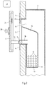
- a first embodiment of the actuator according to the invention is shown in a sectional view. Behind a pretext a concealed cistern 2 is mounted, which has an inspection opening 6, which is aligned with an opening of the prewall. In the area of the inspection opening 6, a mounting frame 4 is mounted, on which a container 10 for receiving perfume and / or cleaning agent 12 is attached. The mounting frame 4 defines an opening 5.
- the container 10 has an opening 11 arranged in the region of the mounting frame 4, via which perfume and / or cleaning agent 12 can be introduced into the container 10.
- the container 10 extends so deeply into the concealed cistern 2, that a provided with a plurality of relatively small through holes 13 portion of the container 10 is immersed in rinsing water-filled concealed cistern 2 in the rinse water.
- an actuating plate 8 is mounted on at least one magnetic closure element 24 and two spaced-apart guides 18.
- the actuating plate 8 has at least one operating element (not shown) for triggering a rinsing process.
- the at least one operating element can be designed, for example, as a pushbutton.
- the guides 18 are each arranged on both sides of the mounting frame 4 and are located substantially at the same height, which is why only one guide 18 can be seen in the drawing.
- the actuating plate 8 is located in a completely covering the inspection opening 6 position.
- a handle is arranged, which is formed for example in the form of a detachable suction cup 28.
- the back of the actuator plate 8 is provided with a magnet which is polarized opposite to the arranged on the mounting frame 4 magnet.
- a magnetic piece of metal may also be attached to the rear side of the actuating plate 8 or to the mounting frame 4.
- the actuating plate 8 on its rear side two horizontally spaced webs 14, at the ends of each a projection 16 is arranged.
- the projections 16 are mounted in the guides 18 of the mounting frame 4.
- the actuating plate 8 must be transferred from a position covering the inspection opening 6 into a position releasing the inspection opening 6.
- a user attach at least one suction cup 28 to the front of the actuator plate and then pull the actuator plate 8 translationally away from the mounting frame 4 to him.
- the projections 16 of the webs 14 of the actuator plate 8 reach after a certain translational movement (displacement) the stop of the guides 18 of the mounting frame 4. This state is in Fig. 2 shown.
- the actuating plate 8 can be pivoted downwards about a pivot axis which runs substantially horizontally.
- the maximum rotation (pivoting) is achieved when the bottom or lower edge of the actuator plate 8 rests against the wall.
- a large part of the inspection opening 6 is released, whereby an additive in the form of perfume and / or cleaning agent 12 can be introduced into the container 10. This situation is in Fig. 3 shown.
- the actuator plate 8 can be pivoted back up and are brought by subsequent displacement in the direction of the mounting frame 4 in the starting position.
- the magnetic closure element 24 ensures a fixation in this position. This condition is in Fig. 4 shown.
- the webs 14, which may also be referred to as arms, are elongated. Furthermore, the webs 14 are preferably designed to be elastic in bending, so that their ends can be elastically moved towards each other in order to be able to release them and thus the actuating plate 8 from the mounting frame 4.
- the respective guide 18 is in the in the FIGS. 1 to 4 illustrated embodiment is preferably formed substantially U-shaped. Yours the two Leg connecting bow that serves as a stop, the front of the mounting frame 4 faces, while the opening of the U-shaped guide 18 faces the interior of the concealed cistern 2.
- the engaging in the guide 18 projection 16 of the web 14 is formed in the form of a cylindrical pin.
- the length of the web 14 is a multiple, for example, more than 3 times the outer diameter of the pin 16th
- a second embodiment of the actuator according to the invention is shown in a sectional view.
- the actuating plate 8 has at its opposite edges, for example at the upper and the lower edge in each case an undercut or a depression (depression) 26.
- the undercuts or indentations (recesses) can be used to move the actuating plate 8 by a translational movement of the wall and thus of the mounting frame 4 away.
- the magnetic closure element 24 is arranged in this second embodiment above the access opening 6 and above the opening 5 defined by the mounting frame 4.
- the webs 14 of the actuator plate 8 have in the in Fig. 5 illustrated embodiment, guides 20, by means of which the actuating plate 8 is mounted on pins 22 which are formed on the mounting frame 4.
- the actuating plate 8 can be moved translationally away from the wall by using the Einmuldungen 26 to strike the pin 22 at the rear loop-shaped end of the guide 20. This condition is in Fig. 5 shown.
- the actuator plate 8 analogous to the in Fig. 3 shown embodiment are pivoted down and the container 10 with perfume and / or detergent 12 are filled.
- the webs 14 are in turn preferably designed to be elastically flexible, so that their ends can move elastically toward one another in order to be able to release them and thus the actuating plate 8 from the mounting frame 4.
- the guide 20 is at the in Fig. 5 illustrated embodiment in the form of a slot or a longitudinal groove in which arranged on the back of the actuator plate 8 or integrally formed web 14 is formed.
- the engaging in the guide 20 projection of the mounting frame 6 is preferably in the form of a cylindrical pin or pin 22 is formed.
- the length of the slot or the longitudinal groove may be a multiple, for example, more than 3 times or 4 times the outer diameter of the pin or pin 22.
Landscapes
- Health & Medical Sciences (AREA)
- Public Health (AREA)
- Engineering & Computer Science (AREA)
- Life Sciences & Earth Sciences (AREA)
- Hydrology & Water Resources (AREA)
- Water Supply & Treatment (AREA)
- Epidemiology (AREA)
- Mechanical Engineering (AREA)
- Aviation & Aerospace Engineering (AREA)
- Detergent Compositions (AREA)
- Sanitary Device For Flush Toilet (AREA)
Priority Applications (1)
| Application Number | Priority Date | Filing Date | Title |
|---|---|---|---|
| PL17176401T PL3260609T3 (pl) | 2016-06-20 | 2017-06-16 | Urządzenie uruchamiające do spłuczki podtynkowej |
Applications Claiming Priority (1)
| Application Number | Priority Date | Filing Date | Title |
|---|---|---|---|
| DE202016103242.3U DE202016103242U1 (de) | 2016-06-20 | 2016-06-20 | Betätigungsvorrichtung für einen Unterputzspülkasten |
Publications (2)
| Publication Number | Publication Date |
|---|---|
| EP3260609A1 EP3260609A1 (de) | 2017-12-27 |
| EP3260609B1 true EP3260609B1 (de) | 2019-09-18 |
Family
ID=59070546
Family Applications (1)
| Application Number | Title | Priority Date | Filing Date |
|---|---|---|---|
| EP17176401.2A Active EP3260609B1 (de) | 2016-06-20 | 2017-06-16 | Betätigungsvorrichtung für einen unterputzspülkasten |
Country Status (5)
| Country | Link |
|---|---|
| EP (1) | EP3260609B1 (pl) |
| DE (1) | DE202016103242U1 (pl) |
| DK (1) | DK3260609T3 (pl) |
| ES (1) | ES2751933T3 (pl) |
| PL (1) | PL3260609T3 (pl) |
Family Cites Families (5)
| Publication number | Priority date | Publication date | Assignee | Title |
|---|---|---|---|---|
| JP2002317481A (ja) * | 2001-04-23 | 2002-10-31 | Toto Ltd | 水洗便器のフラッシュバルブ装置 |
| DE10246866A1 (de) * | 2002-10-08 | 2004-04-22 | Antonio Alessandro | Speicherbehälter, insbesondere Toilettenspülkasten |
| DE102008025904B4 (de) * | 2008-05-29 | 2013-08-08 | GROHEDAL Sanitärsysteme GmbH | Spülkasten mit Revisionsöffnung |
| EP2226437B1 (de) * | 2009-03-06 | 2015-01-28 | Geberit International AG | Spülkasten und Verfahren zum zuführen eines Zusatzmittels bei einem solchen Spülkasten |
| DE102013221616B4 (de) * | 2013-10-24 | 2022-01-13 | Tece Gmbh | Betätigungseinheit zum Auslösen eines Spülvorgangs in einem Spülkasten eines WCs |
-
2016
- 2016-06-20 DE DE202016103242.3U patent/DE202016103242U1/de active Active
-
2017
- 2017-06-16 EP EP17176401.2A patent/EP3260609B1/de active Active
- 2017-06-16 PL PL17176401T patent/PL3260609T3/pl unknown
- 2017-06-16 ES ES17176401T patent/ES2751933T3/es active Active
- 2017-06-16 DK DK17176401T patent/DK3260609T3/da active
Non-Patent Citations (1)
| Title |
|---|
| None * |
Also Published As
| Publication number | Publication date |
|---|---|
| EP3260609A1 (de) | 2017-12-27 |
| PL3260609T3 (pl) | 2020-03-31 |
| ES2751933T3 (es) | 2020-04-02 |
| DE202016103242U1 (de) | 2017-09-21 |
| DK3260609T3 (da) | 2019-11-11 |
Similar Documents
| Publication | Publication Date | Title |
|---|---|---|
| EP2226437B1 (de) | Spülkasten und Verfahren zum zuführen eines Zusatzmittels bei einem solchen Spülkasten | |
| DE1759098A1 (de) | Klosetteinrichtung mit einer zum Waschen der unteren Koerperteile bestimmten Spritzvorrichtung | |
| EP1793721A1 (de) | Vorrichtung, die es erlaubt, eine toilette wahlweise als urinal oder als sitztoilette zu verwenden sowie eine damit ausgestattete toilette | |
| DD296134A5 (de) | Befestigung fuer sanitaerausruestungen | |
| DE2440853A1 (de) | Spuelklosett | |
| DE202006013002U1 (de) | Vorrichtung zur Betätigung eines in Zwei-Mengen-Spültechnik ausgeführten WC-Unterputzspülkastens | |
| DE202013007881U1 (de) | Betätigungsplatte für eine Sanitärspüleinrichtung | |
| DE102007052076B3 (de) | Wasserführendes Haushaltsgerät mit Einspülschale für Flüssigkeiten | |
| DE102013221616B4 (de) | Betätigungseinheit zum Auslösen eines Spülvorgangs in einem Spülkasten eines WCs | |
| EP1889978B1 (de) | Betätigungsvorrichtung für einen Urinal-Unterputzspüler oder WC-Unterputzspülkasten | |
| DE4023316A1 (de) | Klosetteinrichtung | |
| EP1854927A1 (de) | Frontverkleidung mit Betätigungsvorrichtung für Spülkasten | |
| EP3260609B1 (de) | Betätigungsvorrichtung für einen unterputzspülkasten | |
| EP1780343B1 (de) | Sanitärspüleinrichtung mit einer Vorrichtung zum Zuführen von Reinigungsmitteln und/oder Duftstoffen | |
| DE102007048912B4 (de) | Kombi-Spültoilette und Toilettenaufsatz für ein Sitztoilettenbecken | |
| EP3517009B1 (de) | Wc-deckelgarnitur mit mindestens einem befestigungselement und wc mit verriegelungseinrichtung | |
| DE202011051941U1 (de) | Wasch-WC | |
| EP1946688B1 (de) | Sanitärinstallationswand | |
| EP3431673B1 (de) | Behälter zur aufnahme von reinigungsmitteln und/oder duftstoff für einen unterputzspülkasten und unterputzspülkasten mit einem solchen behälter | |
| EP3992380B1 (de) | Duscheinrichtung zur montage an einer schüssel | |
| DE2721348C2 (de) | Halterung für WC-Desodorantien | |
| EP1895066B1 (de) | Betätigungsvorrichtung für einen Urinal-Unterputzspüler oder WC-Unterspülkasten | |
| EP3992382A1 (de) | Duscheinrichtung zur montage an einer schüssel | |
| DE102021126809A1 (de) | Wanddosierspender | |
| DE60107918T2 (de) | Kontrollvorrichtung für Spülkastenventile |
Legal Events
| Date | Code | Title | Description |
|---|---|---|---|
| PUAI | Public reference made under article 153(3) epc to a published international application that has entered the european phase |
Free format text: ORIGINAL CODE: 0009012 |
|
| STAA | Information on the status of an ep patent application or granted ep patent |
Free format text: STATUS: THE APPLICATION HAS BEEN PUBLISHED |
|
| AK | Designated contracting states |
Kind code of ref document: A1 Designated state(s): AL AT BE BG CH CY CZ DE DK EE ES FI FR GB GR HR HU IE IS IT LI LT LU LV MC MK MT NL NO PL PT RO RS SE SI SK SM TR |
|
| AX | Request for extension of the european patent |
Extension state: BA ME |
|
| STAA | Information on the status of an ep patent application or granted ep patent |
Free format text: STATUS: REQUEST FOR EXAMINATION WAS MADE |
|
| 17P | Request for examination filed |
Effective date: 20180223 |
|
| RBV | Designated contracting states (corrected) |
Designated state(s): AL AT BE BG CH CY CZ DE DK EE ES FI FR GB GR HR HU IE IS IT LI LT LU LV MC MK MT NL NO PL PT RO RS SE SI SK SM TR |
|
| GRAP | Despatch of communication of intention to grant a patent |
Free format text: ORIGINAL CODE: EPIDOSNIGR1 |
|
| STAA | Information on the status of an ep patent application or granted ep patent |
Free format text: STATUS: GRANT OF PATENT IS INTENDED |
|
| INTG | Intention to grant announced |
Effective date: 20190404 |
|
| GRAS | Grant fee paid |
Free format text: ORIGINAL CODE: EPIDOSNIGR3 |
|
| GRAA | (expected) grant |
Free format text: ORIGINAL CODE: 0009210 |
|
| STAA | Information on the status of an ep patent application or granted ep patent |
Free format text: STATUS: THE PATENT HAS BEEN GRANTED |
|
| AK | Designated contracting states |
Kind code of ref document: B1 Designated state(s): AL AT BE BG CH CY CZ DE DK EE ES FI FR GB GR HR HU IE IS IT LI LT LU LV MC MK MT NL NO PL PT RO RS SE SI SK SM TR |
|
| REG | Reference to a national code |
Ref country code: GB Ref legal event code: FG4D Free format text: NOT ENGLISH |
|
| REG | Reference to a national code |
Ref country code: CH Ref legal event code: EP |
|
| REG | Reference to a national code |
Ref country code: DE Ref legal event code: R096 Ref document number: 502017002320 Country of ref document: DE |
|
| REG | Reference to a national code |
Ref country code: AT Ref legal event code: REF Ref document number: 1181463 Country of ref document: AT Kind code of ref document: T Effective date: 20191015 |
|
| REG | Reference to a national code |
Ref country code: IE Ref legal event code: FG4D Free format text: LANGUAGE OF EP DOCUMENT: GERMAN |
|
| REG | Reference to a national code |
Ref country code: DK Ref legal event code: T3 Effective date: 20191108 |
|
| REG | Reference to a national code |
Ref country code: CH Ref legal event code: NV Representative=s name: SCHMAUDER AND PARTNER AG PATENT- UND MARKENANW, CH |
|
| REG | Reference to a national code |
Ref country code: NL Ref legal event code: FP |
|
| PG25 | Lapsed in a contracting state [announced via postgrant information from national office to epo] |
Ref country code: BG Free format text: LAPSE BECAUSE OF FAILURE TO SUBMIT A TRANSLATION OF THE DESCRIPTION OR TO PAY THE FEE WITHIN THE PRESCRIBED TIME-LIMIT Effective date: 20191218 Ref country code: SE Free format text: LAPSE BECAUSE OF FAILURE TO SUBMIT A TRANSLATION OF THE DESCRIPTION OR TO PAY THE FEE WITHIN THE PRESCRIBED TIME-LIMIT Effective date: 20190918 Ref country code: NO Free format text: LAPSE BECAUSE OF FAILURE TO SUBMIT A TRANSLATION OF THE DESCRIPTION OR TO PAY THE FEE WITHIN THE PRESCRIBED TIME-LIMIT Effective date: 20191218 Ref country code: FI Free format text: LAPSE BECAUSE OF FAILURE TO SUBMIT A TRANSLATION OF THE DESCRIPTION OR TO PAY THE FEE WITHIN THE PRESCRIBED TIME-LIMIT Effective date: 20190918 Ref country code: HR Free format text: LAPSE BECAUSE OF FAILURE TO SUBMIT A TRANSLATION OF THE DESCRIPTION OR TO PAY THE FEE WITHIN THE PRESCRIBED TIME-LIMIT Effective date: 20190918 Ref country code: LT Free format text: LAPSE BECAUSE OF FAILURE TO SUBMIT A TRANSLATION OF THE DESCRIPTION OR TO PAY THE FEE WITHIN THE PRESCRIBED TIME-LIMIT Effective date: 20190918 |
|
| REG | Reference to a national code |
Ref country code: LT Ref legal event code: MG4D |
|
| PG25 | Lapsed in a contracting state [announced via postgrant information from national office to epo] |
Ref country code: GR Free format text: LAPSE BECAUSE OF FAILURE TO SUBMIT A TRANSLATION OF THE DESCRIPTION OR TO PAY THE FEE WITHIN THE PRESCRIBED TIME-LIMIT Effective date: 20191219 Ref country code: LV Free format text: LAPSE BECAUSE OF FAILURE TO SUBMIT A TRANSLATION OF THE DESCRIPTION OR TO PAY THE FEE WITHIN THE PRESCRIBED TIME-LIMIT Effective date: 20190918 Ref country code: RS Free format text: LAPSE BECAUSE OF FAILURE TO SUBMIT A TRANSLATION OF THE DESCRIPTION OR TO PAY THE FEE WITHIN THE PRESCRIBED TIME-LIMIT Effective date: 20190918 Ref country code: AL Free format text: LAPSE BECAUSE OF FAILURE TO SUBMIT A TRANSLATION OF THE DESCRIPTION OR TO PAY THE FEE WITHIN THE PRESCRIBED TIME-LIMIT Effective date: 20190918 |
|
| REG | Reference to a national code |
Ref country code: ES Ref legal event code: FG2A Ref document number: 2751933 Country of ref document: ES Kind code of ref document: T3 Effective date: 20200402 |
|
| PG25 | Lapsed in a contracting state [announced via postgrant information from national office to epo] |
Ref country code: PT Free format text: LAPSE BECAUSE OF FAILURE TO SUBMIT A TRANSLATION OF THE DESCRIPTION OR TO PAY THE FEE WITHIN THE PRESCRIBED TIME-LIMIT Effective date: 20200120 Ref country code: RO Free format text: LAPSE BECAUSE OF FAILURE TO SUBMIT A TRANSLATION OF THE DESCRIPTION OR TO PAY THE FEE WITHIN THE PRESCRIBED TIME-LIMIT Effective date: 20190918 Ref country code: EE Free format text: LAPSE BECAUSE OF FAILURE TO SUBMIT A TRANSLATION OF THE DESCRIPTION OR TO PAY THE FEE WITHIN THE PRESCRIBED TIME-LIMIT Effective date: 20190918 |
|
| PG25 | Lapsed in a contracting state [announced via postgrant information from national office to epo] |
Ref country code: IS Free format text: LAPSE BECAUSE OF FAILURE TO SUBMIT A TRANSLATION OF THE DESCRIPTION OR TO PAY THE FEE WITHIN THE PRESCRIBED TIME-LIMIT Effective date: 20200224 Ref country code: SK Free format text: LAPSE BECAUSE OF FAILURE TO SUBMIT A TRANSLATION OF THE DESCRIPTION OR TO PAY THE FEE WITHIN THE PRESCRIBED TIME-LIMIT Effective date: 20190918 Ref country code: SM Free format text: LAPSE BECAUSE OF FAILURE TO SUBMIT A TRANSLATION OF THE DESCRIPTION OR TO PAY THE FEE WITHIN THE PRESCRIBED TIME-LIMIT Effective date: 20190918 |
|
| REG | Reference to a national code |
Ref country code: DE Ref legal event code: R097 Ref document number: 502017002320 Country of ref document: DE |
|
| PLBE | No opposition filed within time limit |
Free format text: ORIGINAL CODE: 0009261 |
|
| STAA | Information on the status of an ep patent application or granted ep patent |
Free format text: STATUS: NO OPPOSITION FILED WITHIN TIME LIMIT |
|
| PG2D | Information on lapse in contracting state deleted |
Ref country code: IS |
|
| PG25 | Lapsed in a contracting state [announced via postgrant information from national office to epo] |
Ref country code: IS Free format text: LAPSE BECAUSE OF FAILURE TO SUBMIT A TRANSLATION OF THE DESCRIPTION OR TO PAY THE FEE WITHIN THE PRESCRIBED TIME-LIMIT Effective date: 20200119 |
|
| 26N | No opposition filed |
Effective date: 20200619 |
|
| PG25 | Lapsed in a contracting state [announced via postgrant information from national office to epo] |
Ref country code: SI Free format text: LAPSE BECAUSE OF FAILURE TO SUBMIT A TRANSLATION OF THE DESCRIPTION OR TO PAY THE FEE WITHIN THE PRESCRIBED TIME-LIMIT Effective date: 20190918 |
|
| PG25 | Lapsed in a contracting state [announced via postgrant information from national office to epo] |
Ref country code: MC Free format text: LAPSE BECAUSE OF FAILURE TO SUBMIT A TRANSLATION OF THE DESCRIPTION OR TO PAY THE FEE WITHIN THE PRESCRIBED TIME-LIMIT Effective date: 20190918 |
|
| PG25 | Lapsed in a contracting state [announced via postgrant information from national office to epo] |
Ref country code: LU Free format text: LAPSE BECAUSE OF NON-PAYMENT OF DUE FEES Effective date: 20200616 |
|
| PG25 | Lapsed in a contracting state [announced via postgrant information from national office to epo] |
Ref country code: IE Free format text: LAPSE BECAUSE OF NON-PAYMENT OF DUE FEES Effective date: 20200616 |
|
| PG25 | Lapsed in a contracting state [announced via postgrant information from national office to epo] |
Ref country code: TR Free format text: LAPSE BECAUSE OF FAILURE TO SUBMIT A TRANSLATION OF THE DESCRIPTION OR TO PAY THE FEE WITHIN THE PRESCRIBED TIME-LIMIT Effective date: 20190918 Ref country code: MT Free format text: LAPSE BECAUSE OF FAILURE TO SUBMIT A TRANSLATION OF THE DESCRIPTION OR TO PAY THE FEE WITHIN THE PRESCRIBED TIME-LIMIT Effective date: 20190918 Ref country code: CY Free format text: LAPSE BECAUSE OF FAILURE TO SUBMIT A TRANSLATION OF THE DESCRIPTION OR TO PAY THE FEE WITHIN THE PRESCRIBED TIME-LIMIT Effective date: 20190918 |
|
| PG25 | Lapsed in a contracting state [announced via postgrant information from national office to epo] |
Ref country code: MK Free format text: LAPSE BECAUSE OF FAILURE TO SUBMIT A TRANSLATION OF THE DESCRIPTION OR TO PAY THE FEE WITHIN THE PRESCRIBED TIME-LIMIT Effective date: 20190918 |
|
| PGFP | Annual fee paid to national office [announced via postgrant information from national office to epo] |
Ref country code: AT Payment date: 20220622 Year of fee payment: 6 |
|
| PGFP | Annual fee paid to national office [announced via postgrant information from national office to epo] |
Ref country code: NL Payment date: 20230622 Year of fee payment: 7 Ref country code: FR Payment date: 20230622 Year of fee payment: 7 Ref country code: DK Payment date: 20230627 Year of fee payment: 7 Ref country code: DE Payment date: 20230622 Year of fee payment: 7 Ref country code: CZ Payment date: 20230512 Year of fee payment: 7 |
|
| PGFP | Annual fee paid to national office [announced via postgrant information from national office to epo] |
Ref country code: PL Payment date: 20230612 Year of fee payment: 7 |
|
| PGFP | Annual fee paid to national office [announced via postgrant information from national office to epo] |
Ref country code: BE Payment date: 20230622 Year of fee payment: 7 |
|
| PGFP | Annual fee paid to national office [announced via postgrant information from national office to epo] |
Ref country code: IT Payment date: 20230623 Year of fee payment: 7 Ref country code: GB Payment date: 20230622 Year of fee payment: 7 Ref country code: ES Payment date: 20230726 Year of fee payment: 7 Ref country code: CH Payment date: 20230702 Year of fee payment: 7 |
|
| REG | Reference to a national code |
Ref country code: AT Ref legal event code: MM01 Ref document number: 1181463 Country of ref document: AT Kind code of ref document: T Effective date: 20230616 |
|
| PG25 | Lapsed in a contracting state [announced via postgrant information from national office to epo] |
Ref country code: AT Free format text: LAPSE BECAUSE OF NON-PAYMENT OF DUE FEES Effective date: 20230616 |
|
| PG25 | Lapsed in a contracting state [announced via postgrant information from national office to epo] |
Ref country code: AT Free format text: LAPSE BECAUSE OF NON-PAYMENT OF DUE FEES Effective date: 20230616 |