EP3259447B1 - Meissel mit einem stützelement mit einem zentriereinsatz - Google Patents
Meissel mit einem stützelement mit einem zentriereinsatz Download PDFInfo
- Publication number
- EP3259447B1 EP3259447B1 EP17720767.7A EP17720767A EP3259447B1 EP 3259447 B1 EP3259447 B1 EP 3259447B1 EP 17720767 A EP17720767 A EP 17720767A EP 3259447 B1 EP3259447 B1 EP 3259447B1
- Authority
- EP
- European Patent Office
- Prior art keywords
- support element
- centering
- chisel
- recess
- tool system
- Prior art date
- Legal status (The legal status is an assumption and is not a legal conclusion. Google has not performed a legal analysis and makes no representation as to the accuracy of the status listed.)
- Active
Links
Images


Classifications
-
- E—FIXED CONSTRUCTIONS
- E21—EARTH OR ROCK DRILLING; MINING
- E21D—SHAFTS; TUNNELS; GALLERIES; LARGE UNDERGROUND CHAMBERS
- E21D9/00—Tunnels or galleries, with or without linings; Methods or apparatus for making thereof; Layout of tunnels or galleries
- E21D9/10—Making by using boring or cutting machines
-
- E—FIXED CONSTRUCTIONS
- E21—EARTH OR ROCK DRILLING; MINING
- E21C—MINING OR QUARRYING
- E21C35/00—Details of, or accessories for, machines for slitting or completely freeing the mineral from the seam, not provided for in groups E21C25/00 - E21C33/00, E21C37/00 or E21C39/00
- E21C35/18—Mining picks; Holders therefor
- E21C35/183—Mining picks; Holders therefor with inserts or layers of wear-resisting material
-
- E—FIXED CONSTRUCTIONS
- E21—EARTH OR ROCK DRILLING; MINING
- E21C—MINING OR QUARRYING
- E21C35/00—Details of, or accessories for, machines for slitting or completely freeing the mineral from the seam, not provided for in groups E21C25/00 - E21C33/00, E21C37/00 or E21C39/00
- E21C35/18—Mining picks; Holders therefor
- E21C35/19—Means for fixing picks or holders
- E21C35/193—Means for fixing picks or holders using bolts as main fixing elements
- E21C35/1933—Means for fixing picks or holders using bolts as main fixing elements the picks having a cylindrical shank
-
- E—FIXED CONSTRUCTIONS
- E21—EARTH OR ROCK DRILLING; MINING
- E21C—MINING OR QUARRYING
- E21C35/00—Details of, or accessories for, machines for slitting or completely freeing the mineral from the seam, not provided for in groups E21C25/00 - E21C33/00, E21C37/00 or E21C39/00
- E21C35/18—Mining picks; Holders therefor
- E21C35/19—Means for fixing picks or holders
- E21C35/197—Means for fixing picks or holders using sleeves, rings or the like, as main fixing elements
-
- E—FIXED CONSTRUCTIONS
- E21—EARTH OR ROCK DRILLING; MINING
- E21C—MINING OR QUARRYING
- E21C35/00—Details of, or accessories for, machines for slitting or completely freeing the mineral from the seam, not provided for in groups E21C25/00 - E21C33/00, E21C37/00 or E21C39/00
- E21C35/18—Mining picks; Holders therefor
- E21C35/19—Means for fixing picks or holders
Definitions
- the invention relates to a tool system with a chisel, in particular a round shank chisel, which has a chisel head and a chisel shank, with a support element which has on its underside a seat surface and a centering projection projecting beyond the seat surface, the centering projection having a centering surface which is inclined to the central longitudinal axis of the chisel has, which passes directly or indirectly into the seat surface, the support element along the central longitudinal axis being broken through by a receiving bore with an inner diameter D i for receiving the chisel shaft, with a chisel holder for receiving the chisel shaft, the chisel holder facing the support element having a wear surface for support the seat and a centering receptacle for receiving the centering projection of the support element.
- Such a chisel or tool system are known from US Pat DE102014104040A1 known.
- the diameter of the chisel head increases towards a collar, to which a chisel shaft adjoins.
- the cylindrical chisel shaft is held in a chuck holder in a holding attachment of a chisel holder by means of an adapter sleeve.
- the fixation by means of the clamping sleeve allows the chisel to rotate about its central longitudinal axis while an axial movement is blocked.
- a support element is arranged between the chisel head and the holding attachment, through the central receiving bore of which the chisel shaft is guided.
- the support element Towards the chisel head, the support element has a recess bordered by an edge, the bottom of which represents a support surface, on which the chisel head rests with a support surface.
- the support element forms a seat surface which, towards the center of the support element, merges into a centering surface of a centering projection which runs obliquely to the central longitudinal axis of the chisel.
- a groove In the transition area between the centering surface and the seat surface, a groove is arranged which has a depth of at least 0.3 mm compared to the seat surface.
- the top of the holding attachment of the chisel holder is shaped toward the chisel head corresponding to the underside of the support element. It has a wear surface which rests on the seat of the support element.
- the centering projection of the support element is guided radially in a centering receptacle of the holding projection. Due to the wear of the wear surface during the operation of the tool arrangement with the chisel, a bulge is formed on the wear surface of the chisel holder in the area of the groove of the support element, which bulge engages in the groove. An additional lateral guidance of the support element is achieved by this engagement.
- the penetration of debris into the area of the chisel receptacle is at least reduced by the groove and the bead engaging therein, thereby maintaining the rotatability of the chisel and reducing wear.
- axial play of the chisel in the chisel holder is desirable.
- a larger game is provided for larger chisels than for smaller chisels. If the axial play exceeds the height of the centering attachment, the lateral guidance of the support element through the centering attachment is lost. This leads to increased wear on both the support element and the bit holder.
- a disc for a rotatable cutting bit is known.
- the disc has a plurality of ribs on its front facing the chisel head. These can have a curved shape and can be evenly distributed over the circumference of the disk. On the opposite back, evenly distributed recesses can be formed in the disc.
- the rear side Towards a central receiving bore of the disk, the rear side has a centering projection with a bevelled edge that runs inclined to the central longitudinal axis of the disk. When the disk is mounted, this protrudes into a corresponding chamfer, which is arranged all the way around a bit holder of a bit holder, which results in lateral guidance of the disk.
- the contact surface of the disk is reduced by the ribs and recesses, which leads to improved rotatability of the disk.
- U1 describes a round shank chisel for a milling machine.
- This round shank chisel has a chisel head and a chisel shank.
- a chisel tip is held in the area of the chisel head and forms the actual cutting area of the round shank chisel.
- An adapter sleeve is fitted on the chisel shank of the round shank chisel.
- a support element is arranged in the area between the clamping sleeve and the chisel head.
- the support element has a seat on the underside. This seat merges into a centering shoulder via a recess. The centering shoulder protrudes from the underside of the seat.
- the object of the invention is to provide a tool system which is distinguished by improved wear behavior.
- the object of the invention is achieved with a tool system according to claim 1.
- a centering height measured in the direction of the central longitudinal axis between an end of the centering receptacle facing away from the wear surface and the wear surface or between the end of the centering receptacle and a maximum point of a shoulder projecting beyond the wear surface is designed such that the ratio between the inner diameter D i the receiving bore of the support element and the centering height is less than 8.
- Both the lateral guidance and the sealing effect will be improved in that the support element rests with its seat on the wear surface of the bit holder and that at least one shoulder of the bit holder protruding beyond the wear surface is designed to correspond to a recess of the support element molded into the seat surface and in this protrudes.
- the approach and correspondingly the recess can be throat-shaped or trapezoidal or multi-stage in different contour sections.
- the lateral guidance and the sealing effect can be further improved in that the support element has a guide web that projects beyond the adjacent seat surface and that the bit holder has a web receptacle molded into the wear surface and corresponding to the guide web, into which the guide web projects.
- the seat surface of the support element is both have at least one guide web as well as at least one recess and the wear surface corresponding thereto at least one web receptacle and at least one shoulder.
- the shoulder and / or the web receptacle are attached to the wear surface by means of a shaping method during the manufacture of the bit holder and that the corresponding recess and / or the corresponding guide web are used during operation of the tool system are formed by abrasion of the seat surface and / or that the recess and / or the guide web are attached to the seat surface by a shaping method in the manufacture of the support element and that the corresponding extension and / or the corresponding web receptacle during operation of the tool system by abrasion of the Wear surface are formed. Only one component, namely the chisel holder or the support element, has to be profiled accordingly during production.
- the profile then grinds into the opposite component during operation.
- the grinding process can be carried out over several chisel changes.
- the harder component is advantageously profiled.
- the profiling is particularly preferably carried out on the seat surface of the support element.
- Corresponding lugs and bar receptacles are then ground into the wear surface of the bit holder during operation. Grinding is advantageously carried out during rotational movements of the support element.
- the support element is guided radially through its centering projection in the centering receptacle of the bit holder.
- a collar height measured in the direction of the central longitudinal axis between an end of the centering attachment facing away from the seat surface and the seat surface or between the end of the centering attachment and an inner end is measured in such a manner as to be recessed into the support element that the ratio between the inner diameter D i of the receiving bore of the support element and the collar height is less than 8 and / or that the collar height is greater than an axial play of the mounted in a chisel holder Chisel is.
- the seat surface of the support element lies on a wear surface of the chisel holder.
- the centering lug engages in a centering recess molded into the wear surface and thus leads to a radial stabilization of the positions of the support element. If a recess is formed in the seat, an attachment of the chisel holder engages in it.
- a ratio of less than 8 between the inside diameter D i of the receiving bore of the support element and the collar height ensures sufficient blocking of a lateral movement of the support element.
- the collar height is preferably chosen to be greater than the maximum axial play expected over the life expectancy of the chisel. The centering lug thus leads to a lateral stabilization of the support element even when the chisel is pulled out of the chisel receptacle within the axial play.
- the wear of the support element and the wear surface of the bit holder can be significantly reduced. This applies in particular to an uneven axial load on the support element. In the event of insufficient lateral stabilization of the support element, such an uneven axial load leads to asymmetrical and thus increased wear of the wear surface of the holder.
- the improved lateral guidance of the support element according to the invention results in a more precise centering of the chisel guided in the receiving bore of the support element, as a result of which asymmetrical wear on the wear surface is avoided or at least reduced.
- the low wear of the support element and the wear surface, as well as the improved centering of the chisel stabilize the rotary movement of the chisel. This causes more even wear and thus increases the tool life.
- the centering approach in cooperation with the centering fixture, leads to a labyrinth-like seal. This at least reduces the penetration of debris and dust into the area of the bit holder and the bit shaft.
- the selected ratio of less than 8 between the inside diameter D i of the receiving bore of the support element and the collar height ensures a sufficient seal so that no or only a few foreign substances get into the area of the bit holder and the bit shaft and block the rotary movement of the bit. This reduces the wear on the chisel. It can preferably be provided that the ratio between the inside diameter D i of the receiving bore and the collar height is less than 7.5, preferably less than 7.0, particularly preferably less than 6.5.
- the ratio is less than 7.5, good lateral guidance is achieved even with transverse forces acting directly on the support element, for example through striking material.
- the ratio of the lateral guidance is further improved by a ratio of less than 7.0, so that the simultaneous action of axially aligned forces which are distributed unevenly over the supporting element and of radially acting transverse forces does not lead to a wobbling movement of the supporting element with the resulting high wear.
- a ratio of less than 6.5 sufficient lateral guidance is also achieved towards the end of the service life of the support element and the chisel, if the axial play of the chisel is possibly increased by the wear that has already occurred.
- a radially acting guidance of the support element and thus of the chisel with simultaneous good rotatability of the support element and the chisel can be achieved in that the centering projection and / or the recess are arranged all round to the receiving bore.
- the lateral guidance of the support element can be further improved in that a plurality of recesses of the same or different depth or at least one recess extending spirally around the centering projection are formed in the seat surface and that the ratio between the inside diameter D i of the receiving bore of the support element and the collar height is one of the recesses or the grooves of the spiral recess, preferably the ratio between the inside diameter D i of the receiving bore and the largest collar height determined for a recess or a groove, is less than 8.
- the projected area is retained in the axial direction by a plurality of recesses arranged radially next to one another and corresponding approaches of the bit holder engaging in the recesses, but the contact area between the bit holder and the support element in the radial direction is increased. This enables greater transverse forces to be absorbed. At the same time, the contact area between the chisel holder and the support element is increased, whereby the surface pressure and consequently the wear is reduced.
- the recesses lying next to one another and the lugs engaging therein further improve the sealing effect against penetrating debris material.
- a further improvement of the lateral guidance as well as the sealing and thus the rotatability and the wear of the chisel can be achieved in that a guide web projects beyond the adjacent seat surface at a distance from the centering projection.
- the guide web advantageously engages in a web receptacle which is embedded in the wear surface of the bit holder and corresponds to the guide web.
- the centering lug is advantageously received in a centering receptacle formed in the chisel holder and rotatably supported therein.
- the guide web integrally formed on the seat surface of the support element then grinds itself into the wear surface of the bit holder that has just been executed during the operation of the bit.
- the recess is formed between the centering approach and the guide web and that the centering approach has a greater height than the adjacent seat surface the boardwalk.
- An essential requirement for low wear of the chisel, the support element and the chisel holder is the easy and free rotatability of the support element and the chisel about the central longitudinal axis of the chisel.
- the rotatability can be improved in that transitions between the centering surface, the seat surface, the recess and / or the guide web are straight or rounded. This avoids sharp edges that block the rotation.
- the depth of the recess relative to the seat surface is greater than or equal to 0.3 mm, preferably between 0.3 mm and 2 mm, particularly preferably between 0.5 mm and 1.5 mm. If the recess is selected to be smaller than 0.3 mm, there is no sufficiently pronounced approach for sufficient lateral stabilization of the support element. Recesses down to a depth of 2mm result in a good sealing effect (labyrinth seal) between the shoulder and the recess. If the depth of the recess is chosen between 0.5 mm and 1.5 mm, there is a good combined effect between the seal and the side guide.
- Suitable for common bit types, and associated toolholder support elements can be obtained in that the support element has a receiving bore with an inner diameter D i of 20 mm, and the collar height is greater than 2.5 mm and / or that the supporting element a receiving bore with an inner diameter D i of 22 mm and the collar height is greater than 2.75 mm and / or that the support element has a receiving bore with an inner diameter D i of 25 mm and the collar height is greater than 3.125 mm and / or that the supporting element has a receiving bore with an inner diameter D i of 42 mm and the collar height is greater than 5.25mm.
- support elements with an inner diameter D i of the mounting hole of 20mm or 22mm and a collar height of at least 2.5mm or 2.75mm are suitable.
- support elements with an inner diameter D i of the mounting hole 25mm and a collar height of 3.125mm are suitable.
- support elements with an inner diameter of 42mm D i of the mounting hole and a collar height of at least 5.25mm can be used. With a ratio of less than 8 between the inner diameters D i of the receiving bores of the support elements and the respective collar height, correspondingly higher centering approaches are provided for larger support elements. This ensures that there is sufficient lateral guidance of the support elements in the case of larger chisels with correspondingly greater forces and greater axial play of the chisel.
- Figure 1 shows a side view of a tool system according to the prior art with a chisel 10 in its assembly position on a chisel holder 40.
- the chisel 10 which is designed as a round shank chisel, has a chisel head 13 with a chisel tip 14 made of a hard material, for example hard metal.
- a cylindrical centering section 12 is formed on the chisel head 13, which merges into a cylindrical chisel shaft 11 via a tapering section 12.1.
- the chisel holder 40 has a base part 41, on which a plug-in projection 42 protruding on the underside is formed.
- the base part 41 also carries a one-piece molded attachment lug 43, into which a chisel receptacle 46 is introduced as a cylindrical bore.
- the chisel receptacle 46 is designed as a through hole that is open at its two longitudinal ends. The end of the chisel receptacle 46 facing away from the plug-in attachment 42 opens into a cylindrical one Section 44 of the retaining lug 43. Wear markings 45 in the form of circumferential rings are provided on the outer circumference of the retaining lug 43.
- the chisel 10 is held on its chisel shank 11 by means of a fastening sleeve 20 in the chisel holder 46 of the chisel holder 40.
- the fastening sleeve 20 has holding elements 21 which engage in a circumferential groove 15 of the chisel shank 11.
- the fastening sleeve 20 has a clamping slot 23. This enables the fastening sleeve 20, which is made of resilient material, to be pressed against the wall of the chisel receptacle 46 on account of its inherent tension and thus to be fixed thereon.
- the chisel 10 is thus rotatable about its longitudinal axis, but held axially, fixed in the chisel receptacle 46.
- the axial mounting enables a defined axial play 50 of the chisel 10, indicated by a double arrow, in order to enable the chisel 10 to rotate easily.
- a disc-shaped support element 30 is arranged between the chisel head 13 and the chisel holder 40, as is shown in more detail in FIG Figure 2 is shown, wherein the outer contour of the disk-shaped support element 30 follows a geometric shape and / or an arbitrary shape.
- the chisel holder 40 is mounted with its plug-in attachment 42 in a corresponding holder on a milling drum (not shown) of a milling machine.
- the chisel 10 is fastened to the holding projection 43 of the chisel holder 40 by means of the fastening sleeve 20, together with the support element 30.
- the chisel 10 is guided through the clearing material by a rotary movement of the milling drum.
- the chisel 10 rotates automatically due to acting forces, so that uniform radial wear of the chisel 10 is achieved.
- Figure 2 shows one in the Figure 1 II marked detail of the tool system with a chisel 10 and a support element 30 according to the prior art.
- the chisel head 13 is closed in the direction of the chisel shank 11 with a collar 13.2 which forms a contact surface 13.1.
- This is on one Support surface 32 of the support member 30.
- the support surface 32 is formed within a receptacle 31 on the top of the support element 30. Accordingly, it is limited on the outside by an edge 31.1.
- the support element 30 On the side opposite the support surface 32, the support element 30 has a seat surface 33, with which it rests on a wear surface 47 of the cylindrical section 44 of the holding projection 43.
- the support element 30 is constructed essentially rotationally symmetrically to a central longitudinal axis (M) of the chisel 10.
- the seat surface 33 merges via a circumferential recess 35 into a centering surface 34.1 of a centering projection 34, which is inclined to the central longitudinal axis M.
- the centering projection 34 of the support element 30 is inserted into a correspondingly shaped centering receptacle 48 of the chisel holder 40.
- the support element 30 has a receiving bore 39 through which a guide region 36 for guiding the chisel 10 is formed.
- the centering section 12 of the chisel shank 11 is assigned to the guide area 36.
- a rotary bearing is created between the guide region 36 and the centering section 12.
- the outer diameter of the cylindrical centering section 12 is matched to the inner diameter D i of the receiving bore 39 in the guide region 36 in such a way that free rotation between the support element 30 and the centering section 12 is maintained.
- the play between these two components should be chosen so that there is as little lateral offset as possible (transverse to the central longitudinal axis of the chisel (10)).
- the centering section 12 merges into a cylindrical chisel shaft 11 after a tapering region 12.1.
- the chisel shaft 11 is held in the holding projection 43 of the chisel holder 40 by means of the fastening sleeve 20.
- the fastening sleeve 20 has a chamfer 22 at its upper end.
- the chisel 10 can rotate about the central longitudinal axis.
- the free rotatability ensures that the chisel 10 is even wears over its entire circumference.
- the rotation and the high mechanical load on the chisel 10 also result in wear on the chisel holder 40, mainly in the upper section 44 of the holding projection 43.
- the wear surface 47 is rubbed off by the load.
- the existing wear of the retaining lug 43 can be done in Figure 1 shown wear marks 45 are evaluated.
- a support 47 30 is provided with an additional lateral guidance through a projection 47. 1 that is formed in accordance with the contour of the recess 35, which has a positive effect on the rotatability of the support element 30 and thus of the chisel 10.
- the centering surface 34.1 merges tangentially into the surface of the recess 35, so that no edges which hinder the rotatability are formed.
- the surface of the recess 35 merges into the seat 33 via a rounding section without sharp edges.
- the recess 35 counteracts forces which act radially inward on the support element 30.
- the radially inner surface section counteracts radially outward forces. This reduces the force which has to be absorbed by the centering surface 34.1, which in this area leads to a reduced surface pressure and correspondingly to a reduced wear.
- this support also counteracts a wobble movement in the disk plane of the support element 30, which reduces wear on the chisel holder 40.
- the recess with its counterpart ground from the wear surface 47 serves as a labyrinth-like seal. Debris that gets between the seat surface 33 and the wear surface 47 is prevented from advancing by this seal and thus only reaches the area of the chisel shaft 11 to a reduced extent.
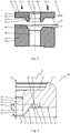
- Figure 3 shows a schematic representation of the wear of the wear surface 47 of the chisel holder 40 in the case of a known support element 30 and in the case of an asymmetrical loading of the support element 30.
- the disk-shaped support element 30 is provided by a flat support surface 32 and an opposite, also flat seat surface 33 limited.
- the centering projection 34 is formed with its centering surface 34.1 all around the central receiving bore 39 on the seat surface 33.
- the receiving bore 39 has an inner diameter D i 58.
- the receiving bore 39 On the side of the support surface 32, the receiving bore 39 has an insertion phase 36.1.
- the asymmetrical load is represented by two arrows of different lengths, which symbolize a first force 55.1 and a larger second force 55.2.
- the asymmetrical introduction of force can be caused, for example, by the position of the bit holder 40 in relation to the direction of rotation of the milling drum.
- Such a non-uniform axial load leads to an asymmetrical wear on the wear surface 47 of the bit holder 40 with a larger lateral movement (radial movement 54) of the support element 30.
- This is due to a wear angle 56 course of the wear surface which is inclined by a wear angle 56 with respect to a plane running perpendicular to the central longitudinal axis M. 47 indicated.
- the radial movement 54 is made possible with insufficient lateral guidance of the support element 30.
- the support element 30 guiding the chisel 10 lies on the wear surface 47 at an angle to the central longitudinal axis M. So that the receiving bore 39 is not exactly aligned with the central longitudinal axis M of the bit holder 46. Due to this incorrect position, the smooth rotation of the chisel 10 can be hindered or prevented.
- Figure 4 shows a side sectional view of a section of a support element 30 according to the invention in a first embodiment.
- the support surface 32 is arranged in the receptacle 31 for mounting the chisel head 13.
- the recess 35 has a first radius 35.1 in a range between 0.5 mm and 6 mm, in the present case 1.5 mm.
- the depth of the recess 35 relative to the seat 33 is preferably in a range between 0.3 mm and 2 mm, preferably between 0.5 mm and 1.5 mm, in the present case 1.0 mm.
- the recess 35 merges into the seat 33 over a rounded region with a second radius 35.2.
- An apex 35.5 forms an inner end 53 of the recess 35.
- the centering projection 34, facing away from the seat 33, is closed off by a web-shaped end 34.2.
- a collar height 52 is represented by a double arrow.
- the collar height 52 in the present exemplary embodiment represents the distance, measured in the direction of the central longitudinal axis M, between the end 34.2 of the centering projection 34 and the end 53 of the recess 35.
- the recess 35 is formed in the seat 33 of the support element 30.
- the support element 30 lies with its seat 33 on the in Figure 2 shown wear surface 47 of the chisel holder 40. If the wear surface 47 is flat up to its transition into the centering receptacle 48, the shoulder 47.1 grinds into the recess 35 during use of the tool system and the support element 30 rotating about the central longitudinal axis M.
- the projection 47.1 corresponding to the recess 35 is already molded onto the wear surface 47 during the manufacture of the bit holder 40.
- the approach 47.1 can already have its final contour adapted to the recess 35.
- the projection 47.1 is only approximately adapted to the contour of the recess 35 during the manufacture of the chisel holder 40.
- the final contour of the shoulder 47.1 then results during the use of the tool system, in which the shoulder 47.1 grinds into the recess 35.
- the seat 33 can be designed without a recess 35 formed therein. Instead, the shoulder 47.1 is molded onto the wear surface 47 of the bit holder 40. During operation, the shoulder 47.1 now grinds into the wear surface 33 of the support element 30 and thus forms the recess 35.
- An outer diameter 51 of the support element 30 and the inner diameter 58 of the receiving bore 39 of the support element 30 are each marked by an arrow.
- the outer diameter 51 corresponds to an outer diameter 57 of the seat 33.
- the collar height 52 is designed such that the ratio between the inside diameter 58 of the receiving bore 39 of the support element 30 and the collar height 52 assumes a value less than 8.
- the collar height 52 is predetermined by the axial dimensioning of the centering projection 34 and the recess 35.
- the collar height 52 is designed such that it is greater than the axial play 50 of the chisel 10 and thus of the support element 30.
- the dimensioning of the collar height 52 as a function of the inner diameter 58 of the receiving bore 39 of the support element 30 takes into account the larger permissible axial play 52 for larger tool systems. A sufficient lateral guidance of the support element 30 and thus of the chisel 10 is thus always guaranteed, regardless of the tool size.
- the easy rotatability of the support element 30 and the chisel 10 is further maintained by the rounded or rectilinear and thus edge-free transitions between the centering surface 34.1, the receptacle 35 and the seat surface 33. Sharp transitions easily cause the support element 30 to tilt relative to the bit holder 40 and prevent rotation. This can be avoided by the rounded or straight transitions.
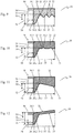
- FIGS. 5 to 14 each show a section of a support element 30 in further embodiments in schematic sectional side views.
- the support elements 30 have a flat support surface 32.
- the receptacle 31 then forms the support surface 32, on which the chisel head 13 rests with its support surface 13.1.
- An insertion chamfer 36.1 is arranged at the transition from the support surface 32 into the guide area 36. Alternatively, the transition can also be rounded.
- a guide web 37 is arranged on the seat surface 33.
- the guide web 37 runs at a distance from the centering projection 34. It has a trapezoidal contour with side surfaces running at an angle to the seat surface 33.
- the guide webs 37 are closed off from the chisel holder 40 by a seat surface section 33.1.
- the recess 35 is formed between the centering shoulder 34 and the guide web 37. It also has a trapezoidal contour.
- the end 53 of the recess 35 is formed by a contact surface 35.3.
- the contact surface 35.3 lies in the same plane as the seat 33 on the side of the guide web 37. Towards the central longitudinal axis M, the contact surface 35.3 merges into the inclined centering surface 34.1 of the centering projection 34.
- the centering extension 34 is closed off by its web-shaped end 34.2 towards the bit holder 40.
- the collar height 52 is measured in the direction of the central longitudinal axis between the end 34.2 of the centering projection 34 and the end 53 of the recess 35, as is shown by a double arrow.
- the ratio between the inner diameter 58 of the receiving bore 39 of the support element 30 and the collar height 52 is chosen to be less than 8, in the present case less than 6.5.
- the guide web 37 rests on the wear surface 47 of the bit holder 40. Due to the rotation of the support element 30, it grinds itself into the wear surface 47 and thus forms a corresponding web receptacle in the end surface of the bit holder 40. As a result, both the lateral guidance of the support element 30 and the sealing effect are significantly improved.
- the transition from the centering surface 34.1 to the contact surface 35.3 and / or the transition from the contact surface 35.3 to the adjacent side surface of the guide web 37 and / or the transition from the opposite side surface of the guide web 37 to the adjacent seat surface 33 can be rounded off his.
- the transitions from the side surfaces to the seat portion 33.1 be rounded. This way, sharp edges can be avoided. This leads to an improved rotatability of the support element 30.
- Support element 30 shown is also a trapezoidal guide web 37 is arranged on the side of the support element 30 facing the bit holder 40.
- a recess 35 formed between the guide web 37 and the centering projection 34 has a throat-shaped contour.
- the radius of the recess 35 is selected such that its surface merges tangentially into the centering surface 34.1 and the adjacent side surface of the guide web 37.
- the collar height 52 corresponds to the distance running in the direction of the central longitudinal axis M between the end 34.2 of the centering projection 34 and the apex 35.5 of the throat-shaped recess 35.
- the seat 33 of the in Figure 7 Support element 30 shown merges directly into the centering surface 34.1 of the centering projection 34.
- a groove-shaped recess 35 is let into the seat 33.
- the collar height 52 is measured along the central longitudinal axis M between the end 34.2 of the centering projection 34 and the apex 35.5 of the groove-shaped recess 35.
- the recess 35 arranged comparatively far outside on the support element 30 results in particularly good stabilization of the rotational movement of the support element 30.
- FIG 8 A support element 30 with a multi-stage recess 35 and a guide web 37 is shown.
- the centering surface 34.1 runs into the recess 35 and merges there into a contact surface 35.3 arranged transversely to the central longitudinal axis M, in particular perpendicularly to the central longitudinal axis M.
- a groove-shaped area 35.4 adjoins the contact surface 35.3 as a further deepening of the recess 35.
- the surface of the groove-shaped region 35.4 merges tangentially into the adjacent side surface of the guide web 37.
- the Trapezoidal shaped guide web 37 forms a seat surface section 33.1, which is connected to the further seat surface 33 via the outer side surface of the guide web 37.
- the contact surface 35.3, the seat surface section 33.1 and the outer seat surface 33 run transversely, in particular perpendicularly to the central longitudinal axis M.
- the contact surface 35.3 is molded further into the support element 30 than the seat surface 33.
- the collar height 52 is between the end 34.2 of the centering projection 34 and the The apex 35.5 is measured as the end 53 of the groove-shaped region 35.4 of the recess 35.
- the different planes in which the support surface 33, the support surface section 33.1 and the contact surface 35.3 are arranged lead both to a good lateral guidance of the support element 30 and to a good sealing effect.
- the embodiment of the support element 30 shown is formed with concentrically arranged recesses 35 around the centering projection 34 in the support element 30.
- a wavy contour is thus formed, the surface of which represents the seat surface 33.
- the recesses 35 are formed by a groove which spirally surrounds the centering projection 34.
- the collar height 52 is measured between the end 34.2 of the centering projection 34 and the apex 35.5 of the innermost recess 35. In the case of adjacent recesses 35 of different depths, the collar height 52 is preferably determined at the end 53 of the deepest recess 35. A good rotatability of the support element 30 is ensured by the recesses 35 arranged all around the centering projection 34.
- Figure 10 shows a support element with a flat seat 33, in which two concentrically extending, groove-shaped recesses 35 are incorporated. This arrangement also achieves good rotatability, good lateral stabilization and a good sealing effect against penetrating debris.
- the support element 30 shown has a rectilinear seat surface 33 which is oriented obliquely to the central longitudinal axis M.
- the maximum recess in the support element 30 is formed in the rounded transition area from the centering surface 34.1 into the wear surface 33.
- Both the centering surface 34.1 and the wear surface 33 have a radial stabilizing effect on the position of the support element 30 due to their orientation obliquely to the central longitudinal axis M.
- the collar height 52 is from the end 34.2 of the centering projection 34 to the end 53 in the transition region from the centering surface 34.1 to the wear surface 33 measured.
- both the support surface 32 and the seat surface 33 extend obliquely to the central longitudinal axis M.
- the support surface 32 and the seat surface 33 are preferably arranged plane-parallel to one another.
- the largest distance measured in the direction of the central longitudinal axis M between the end 34.2 of the centering section 34 and the seat surface 33 results from the outer edge of the support element 30, so that this distance forms the collar height 52.
- both the centering surface 34.1 and the seat surface 33 which is oriented obliquely to the central longitudinal axis M, have a radially stabilizing effect on the support element 30.
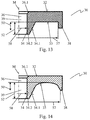
- Figure 13 shows a support element 30 with an outer bend 38.
- the centering surface 34.1 of the centering projection 34 merges into the support surface 33 which runs flat.
- the support surface 33 is preferably oriented perpendicular to the central longitudinal axis M.
- the outer diameter 57 of the seat surface 33 is selected to be slightly larger than the diameter of the wear surface 47 of the bit holder 40.
- the in The exemplary embodiment shown here has a rectangular fold 38 which extends in the direction of the chisel holder 40. When mounted, it engages around the upper section 44 of the holding projection 43 and thus leads to an additional lateral stabilization of the support element 30. Furthermore, the fold 38 protects the area between the chisel holder 40 and the support element 30 from penetrating material.
- the transitions from the centering surface 34.1 into the seat surface 33 or from the seat surface 33 to the fold 38 can be rounded.
- the collar height 52 is marked by a double arrow as the distance between the end 34.2 of the centering section 34 and the seat 33.
- Figure 14 shows a support element 30 with a bevel 38 encompassing the holding projection 43 of the chisel holder 40.
- the seating surface 33 is in this case arched inward. This makes one compared to the one in Figure 13 Embodiment shown improved lateral guidance and improved rotatability about the central longitudinal axis M of the support member 30 achieved.
- the distance between the end 34.2 of the centering projection 34 and the inner end 53 of the seat 33 corresponds to the collar height 52.
- the respective collar height 52 is designed to be greater than the permissible axial play 50 of the chisel 10 and thus of the support element 30.
- sufficient lateral guidance of the support element 30 is achieved even with a maximum deflection of the chisel 10 from the chisel holder 46. Due to the different possible contours of the side of the support element 30 facing the chisel holder 40 and the correspondingly designed upper side of the chisel holder 40, the lateral guidance and the sealing against penetrating foreign bodies can be adapted to the corresponding requirements.
- the ground-in centering projection 34 forms a so-called labyrinth seal on the end face of the holder shaft, in order to protect the inner bore 39 against undesired contamination or contamination from the cavity that forms between a centering projection 34, a guide web 37 and / or to be able to specifically derive a recess 35 and the end face of a holder shaft due to an axial displacement of the chisel.
- Such interruptions can additionally be formed in a radial longitudinal extension of different lengths in order to further improve the discharge of contaminants.
Landscapes
- Engineering & Computer Science (AREA)
- Mining & Mineral Resources (AREA)
- Life Sciences & Earth Sciences (AREA)
- General Life Sciences & Earth Sciences (AREA)
- Geochemistry & Mineralogy (AREA)
- Geology (AREA)
- Mechanical Engineering (AREA)
- Environmental & Geological Engineering (AREA)
- Drilling And Exploitation, And Mining Machines And Methods (AREA)
- Percussive Tools And Related Accessories (AREA)
- Earth Drilling (AREA)
- Cutting Tools, Boring Holders, And Turrets (AREA)
- Manipulator (AREA)
- Container, Conveyance, Adherence, Positioning, Of Wafer (AREA)
- Milling Processes (AREA)
- Braking Arrangements (AREA)
- Automatic Assembly (AREA)
- Polishing Bodies And Polishing Tools (AREA)
- Adornments (AREA)
Priority Applications (4)
| Application Number | Priority Date | Filing Date | Title |
|---|---|---|---|
| RS20200437A RS60169B1 (sr) | 2016-05-12 | 2017-04-28 | Dleto sa nosećim elementom sa centrirajućim umetkom |
| DK19194833.0T DK3608504T3 (da) | 2016-05-12 | 2017-04-28 | Mejsel med et støtteelement med en centreringskrave |
| EP19194833.0A EP3608504B1 (de) | 2016-05-12 | 2017-04-28 | Meissel mit einem stützelement mit einem zentrieransatz |
| PL17720767T PL3259447T3 (pl) | 2016-05-12 | 2017-04-28 | Nóż z elementem podpierającym z nasadką centrującą |
Applications Claiming Priority (2)
| Application Number | Priority Date | Filing Date | Title |
|---|---|---|---|
| DE102016108808.0A DE102016108808A1 (de) | 2016-05-12 | 2016-05-12 | Meißel mit einem Stützelement mit einem Zentrieransatz |
| PCT/EP2017/060157 WO2017194328A1 (de) | 2016-05-12 | 2017-04-28 | MEIßEL MIT EINEM STÜTZELEMENT MIT EINEM ZENTRIEREINSATZ |
Related Child Applications (2)
| Application Number | Title | Priority Date | Filing Date |
|---|---|---|---|
| EP19194833.0A Division EP3608504B1 (de) | 2016-05-12 | 2017-04-28 | Meissel mit einem stützelement mit einem zentrieransatz |
| EP19194833.0A Division-Into EP3608504B1 (de) | 2016-05-12 | 2017-04-28 | Meissel mit einem stützelement mit einem zentrieransatz |
Publications (2)
| Publication Number | Publication Date |
|---|---|
| EP3259447A1 EP3259447A1 (de) | 2017-12-27 |
| EP3259447B1 true EP3259447B1 (de) | 2020-01-22 |
Family
ID=58664690
Family Applications (2)
| Application Number | Title | Priority Date | Filing Date |
|---|---|---|---|
| EP17720767.7A Active EP3259447B1 (de) | 2016-05-12 | 2017-04-28 | Meissel mit einem stützelement mit einem zentriereinsatz |
| EP19194833.0A Active EP3608504B1 (de) | 2016-05-12 | 2017-04-28 | Meissel mit einem stützelement mit einem zentrieransatz |
Family Applications After (1)
| Application Number | Title | Priority Date | Filing Date |
|---|---|---|---|
| EP19194833.0A Active EP3608504B1 (de) | 2016-05-12 | 2017-04-28 | Meissel mit einem stützelement mit einem zentrieransatz |
Country Status (18)
| Country | Link |
|---|---|
| US (2) | US10738610B2 (pl) |
| EP (2) | EP3259447B1 (pl) |
| JP (1) | JP6548747B2 (pl) |
| KR (2) | KR20180006960A (pl) |
| CN (1) | CN107614831B (pl) |
| AU (1) | AU2017245306B2 (pl) |
| BR (2) | BR122022014393B1 (pl) |
| CA (1) | CA2982108C (pl) |
| DE (2) | DE102016108808A1 (pl) |
| DK (2) | DK3608504T3 (pl) |
| ES (2) | ES2784966T3 (pl) |
| FI (1) | FI3608504T3 (pl) |
| PL (2) | PL3259447T3 (pl) |
| PT (1) | PT3608504T (pl) |
| RS (2) | RS64064B1 (pl) |
| RU (1) | RU2683440C1 (pl) |
| TW (1) | TWI635214B (pl) |
| WO (1) | WO2017194328A1 (pl) |
Cited By (3)
| Publication number | Priority date | Publication date | Assignee | Title |
|---|---|---|---|---|
| US11585217B2 (en) | 2021-03-11 | 2023-02-21 | Kennametal Inc. | Washerless cutting tool assembly |
| USD982633S1 (en) | 2021-03-11 | 2023-04-04 | Kennametal Inc. | Washerless cutting tool assembly |
| US12006825B2 (en) | 2021-03-11 | 2024-06-11 | Kennametal Inc. | Cutting tool with shank portion configured for limiting rotation and controlling orientation of the tool |
Families Citing this family (14)
| Publication number | Priority date | Publication date | Assignee | Title |
|---|---|---|---|---|
| DE102016108808A1 (de) | 2016-05-12 | 2017-11-16 | Betek Gmbh & Co. Kg | Meißel mit einem Stützelement mit einem Zentrieransatz |
| DE102017123368A1 (de) * | 2017-10-09 | 2019-04-11 | Wirtgen Gmbh | Meißelhalter |
| DE102018109150A1 (de) * | 2018-04-17 | 2019-10-17 | Betek Gmbh & Co. Kg | Fräsmeißel |
| DE202018006276U1 (de) | 2018-04-17 | 2019-10-24 | Betek Gmbh & Co. Kg | Fräsmeißel |
| DE102018109151A1 (de) | 2018-04-17 | 2019-10-17 | Betek Gmbh & Co. Kg | Fräsmeißel |
| DE102018109147A1 (de) * | 2018-04-17 | 2019-10-17 | Betek Gmbh & Co. Kg | Fräsmeißel |
| US20200149397A1 (en) * | 2018-11-13 | 2020-05-14 | Randall Walter Ojanen | Point attack insert for rotatable cutting tool |
| CN111576174A (zh) * | 2020-05-31 | 2020-08-25 | 苏州五元素机械制造有限公司 | 一种凿刀 |
| CN111809490B (zh) * | 2020-07-24 | 2025-07-11 | 江苏五元素机械制造有限公司 | 具有双限位盘的凿刀 |
| KR102434767B1 (ko) * | 2022-02-16 | 2022-08-22 | 문정호 | 커팅픽 조립체 |
| USD1015136S1 (en) | 2022-02-21 | 2024-02-20 | Kennametal Inc. | Washer for cutting tools |
| US12011852B2 (en) | 2022-02-21 | 2024-06-18 | Kennametal Inc. | Washers for Rotatable Cutting Tools |
| TWM639375U (zh) * | 2022-11-22 | 2023-04-01 | 永沛得股份有限公司 | 墊片及銑刨刀結構 |
| US20240384653A1 (en) * | 2023-05-19 | 2024-11-21 | Caterpillar Paving Products Inc. | Non-rotating bit for cutting tool |
Citations (2)
| Publication number | Priority date | Publication date | Assignee | Title |
|---|---|---|---|---|
| DE202010018061U1 (de) | 2009-10-19 | 2013-12-16 | Betek Gmbh & Co. Kg | Meißel, insbesondere Rundschaftmeißel |
| DE102014104040A1 (de) | 2014-03-24 | 2015-09-24 | Betek Gmbh & Co. Kg | Meißel, insbesondere Rundschaftmeißel |
Family Cites Families (50)
| Publication number | Priority date | Publication date | Assignee | Title |
|---|---|---|---|---|
| DE3233123C2 (de) * | 1982-09-07 | 1985-09-19 | Wolfgang 6603 Sulzbach Preinfalk | Axialhalterung für Rundschaftmeißel |
| SU1461907A1 (ru) * | 1987-02-09 | 1989-02-28 | В.А.Ленин | Устройство дл креплени резцов горных машин |
| SE461165B (sv) | 1987-06-12 | 1990-01-15 | Hans Olav Norman | Verktyg foer brytning, avverkning eller bearbetning av fasta material |
| SU1469124A1 (ru) * | 1987-07-21 | 1989-03-30 | Институт горного дела им.А.А.Скочинского | Породоразрушающий инструмент |
| US5251964A (en) * | 1992-08-03 | 1993-10-12 | Gte Valenite Corporation | Cutting bit mount having carbide inserts and method for mounting the same |
| DE4322402C2 (de) | 1993-07-06 | 1996-06-20 | Wirtgen Gmbh | Schneidkörper für eine Schrämmaschine |
| RU2123594C1 (ru) * | 1995-11-27 | 1998-12-20 | Совместное российско-германское предприятие "Мосвирт" | Защитный элемент режущего инструмента |
| US5725283A (en) * | 1996-04-16 | 1998-03-10 | Joy Mm Delaware, Inc. | Apparatus for holding a cutting bit |
| US6357832B1 (en) * | 1998-07-24 | 2002-03-19 | The Sollami Company | Tool mounting assembly with tungsten carbide insert |
| US6113195A (en) * | 1998-10-08 | 2000-09-05 | Sandvik Ab | Rotatable cutting bit and bit washer therefor |
| UA73489C2 (en) * | 1998-12-08 | 2005-08-15 | Genisis Mining Technologies Pr | Cutting arrangement and sleeve for it |
| DE19908656C1 (de) | 1999-02-27 | 2000-08-31 | Wirtgen Gmbh | Meißelhalterwechselsystem |
| US6702393B2 (en) | 2001-05-23 | 2004-03-09 | Sandvik Rock Tools, Inc. | Rotatable cutting bit and retainer sleeve therefor |
| US6824225B2 (en) | 2001-09-10 | 2004-11-30 | Kennametal Inc. | Embossed washer |
| US6758530B2 (en) * | 2001-09-18 | 2004-07-06 | The Sollami Company | Hardened tip for cutting tools |
| RU2198292C1 (ru) | 2001-11-12 | 2003-02-10 | Леванковский Игорь Анатольевич | Устройство для разрушения минеральных и искусственных материалов |
| DE10161713B4 (de) | 2001-12-15 | 2004-02-05 | Wirtgen Gmbh | Meißelhalterwechselsystem |
| DE10331970B4 (de) * | 2003-07-14 | 2008-01-31 | Wirtgen Gmbh | Baumaschine |
| DE102004030691B4 (de) | 2004-06-24 | 2008-12-18 | Wirtgen Gmbh | Werkzeug-Haltevorrichtung |
| DE102004057302B4 (de) | 2004-11-26 | 2011-01-13 | Wirtgen Gmbh | Meißelhalter |
| US20060125306A1 (en) * | 2004-12-15 | 2006-06-15 | The Sollami Company | Extraction device and wear ring for a rotatable tool |
| DE102005003734B3 (de) | 2005-01-26 | 2006-02-16 | Wirtgen Gmbh | Meißelhaltersystem |
| US20070257545A1 (en) * | 2006-05-08 | 2007-11-08 | Sandvik Intelectual Property Ab | Cutting tool and method of assembling the cutting tool |
| DE102006029300B3 (de) * | 2006-06-23 | 2007-11-29 | Betek Bergbau- Und Hartmetalltechnik Karl-Heinz Simon Gmbh & Co. Kg | Rundschaftmeißel |
| US7413256B2 (en) * | 2006-08-11 | 2008-08-19 | Hall David R | Washer for a degradation assembly |
| DE102007030658A1 (de) * | 2007-07-02 | 2009-01-15 | Betek Bergbau- Und Hartmetalltechnik Karl-Heinz Simon Gmbh & Co. Kg | Schaftmeißel |
| DE202007010047U1 (de) | 2007-07-02 | 2007-09-27 | Wirtgen Gmbh | Werkzeug |
| DE102007051911B4 (de) * | 2007-10-29 | 2011-06-16 | Betek Bergbau- Und Hartmetalltechnik Karl-Heinz Simon Gmbh & Co. Kg | Schaftmeißel |
| US7832808B2 (en) | 2007-10-30 | 2010-11-16 | Hall David R | Tool holder sleeve |
| WO2009072958A1 (en) * | 2007-12-05 | 2009-06-11 | Sandvik Intellectual Property Ab | Breaking or excavating tool with cemented tungsten carbide insert and ring, material removing machine incorporating such a tool and method of manufacturing such a tool |
| PL393315A1 (pl) * | 2008-05-20 | 2011-04-26 | Sandviki Intellectual Property Ab | Węglikowa powierzchnia tarcia zespołu klocka i tulei |
| DE102008045825B3 (de) | 2008-09-05 | 2010-05-27 | Wirtgen Gmbh | Meißelhalter für eine Schrämmaschine, Straßenfräse, Suface-Miner oder dergleichen |
| CN102472098A (zh) | 2009-08-04 | 2012-05-23 | 山特维克知识产权股份有限公司 | 用于刀具截齿的不旋转的垫圈、刀具和块体组件、减少冲蚀磨损的方法和材料去除机器 |
| DE102009059188A1 (de) | 2009-12-17 | 2011-06-22 | Wirtgen GmbH, 53578 | Meißelhalter und Basisteil |
| DE102009059189A1 (de) | 2009-12-17 | 2011-06-22 | Wirtgen GmbH, 53578 | Meißelhalter und Basisteil zur Aufnahme eines Meißelhalters |
| US9376911B2 (en) | 2010-12-03 | 2016-06-28 | Wirtgen Gmbh | Chisel holder, and chisel holder system comprising a chisel holder and a base part |
| TWI468253B (zh) | 2010-12-03 | 2015-01-11 | Wirtgen Gmbh | 刀架以及具有刀架和基礎部件的刀架系統 |
| AU2011334838B2 (en) | 2010-12-03 | 2016-05-19 | Wirtgen Gmbh | Chisel holder |
| DE102010061019A1 (de) | 2010-12-03 | 2012-06-06 | Betek Gmbh & Co. Kg | Meißelhalter und Werkzeugunterteil für einen Meißelhalter |
| HUE055782T2 (hu) | 2010-12-03 | 2021-12-28 | Wirtgen Gmbh | Késtartó |
| DE102011051525A1 (de) | 2011-07-04 | 2013-01-10 | Wirtgen Gmbh | Meißelhalter für eine Bodenbearbeitungsmaschine |
| DE102011054384A1 (de) | 2011-10-11 | 2013-04-11 | Betek Gmbh & Co. Kg | Meißelhalter |
| DE102011054393A1 (de) | 2011-10-11 | 2013-04-11 | Betek Gmbh & Co. Kg | Schaftmeißel |
| EP2766571A2 (de) | 2011-10-11 | 2014-08-20 | Betek GmbH & Co. KG | Schaftmeissel und halter |
| USD711442S1 (en) | 2013-07-15 | 2014-08-19 | Wirtgen Gmbh | Chisel holder |
| DE102013110680A1 (de) * | 2013-09-26 | 2015-03-26 | Betek Gmbh & Co. Kg | Meißelhalter und Kombination eines Meißelhalters mit einem Meißel |
| DE102013110676A1 (de) * | 2013-09-26 | 2015-03-26 | Betek Gmbh & Co. Kg | Meißel |
| US9028008B1 (en) * | 2014-01-16 | 2015-05-12 | Kennametal Inc. | Cutting tool assembly including retainer sleeve with compression band |
| CN204530413U (zh) * | 2015-04-09 | 2015-08-05 | 中联重科股份有限公司 | 铣刨刀具及具有其的铣刨机 |
| DE102016108808A1 (de) | 2016-05-12 | 2017-11-16 | Betek Gmbh & Co. Kg | Meißel mit einem Stützelement mit einem Zentrieransatz |
-
2016
- 2016-05-12 DE DE102016108808.0A patent/DE102016108808A1/de active Pending
-
2017
- 2017-04-28 RU RU2017140043A patent/RU2683440C1/ru active
- 2017-04-28 CN CN201780001772.9A patent/CN107614831B/zh active Active
- 2017-04-28 PL PL17720767T patent/PL3259447T3/pl unknown
- 2017-04-28 ES ES17720767T patent/ES2784966T3/es active Active
- 2017-04-28 WO PCT/EP2017/060157 patent/WO2017194328A1/de not_active Ceased
- 2017-04-28 DK DK19194833.0T patent/DK3608504T3/da active
- 2017-04-28 PL PL19194833.0T patent/PL3608504T3/pl unknown
- 2017-04-28 DK DK17720767.7T patent/DK3259447T3/da active
- 2017-04-28 EP EP17720767.7A patent/EP3259447B1/de active Active
- 2017-04-28 RS RS20230213A patent/RS64064B1/sr unknown
- 2017-04-28 CA CA2982108A patent/CA2982108C/en active Active
- 2017-04-28 KR KR1020177035821A patent/KR20180006960A/ko not_active Ceased
- 2017-04-28 BR BR122022014393-8A patent/BR122022014393B1/pt active IP Right Grant
- 2017-04-28 FI FIEP19194833.0T patent/FI3608504T3/fi active
- 2017-04-28 PT PT191948330T patent/PT3608504T/pt unknown
- 2017-04-28 BR BR112017021807-0A patent/BR112017021807B1/pt active IP Right Grant
- 2017-04-28 RS RS20200437A patent/RS60169B1/sr unknown
- 2017-04-28 EP EP19194833.0A patent/EP3608504B1/de active Active
- 2017-04-28 JP JP2017562321A patent/JP6548747B2/ja active Active
- 2017-04-28 ES ES19194833T patent/ES2940057T3/es active Active
- 2017-04-28 DE DE202017006713.7U patent/DE202017006713U1/de active Active
- 2017-04-28 KR KR1020207018057A patent/KR102255741B1/ko active Active
- 2017-04-28 AU AU2017245306A patent/AU2017245306B2/en active Active
- 2017-05-09 TW TW106115375A patent/TWI635214B/zh active
- 2017-11-17 US US15/816,050 patent/US10738610B2/en active Active
-
2020
- 2020-07-30 US US16/943,547 patent/US11131188B2/en active Active
Patent Citations (2)
| Publication number | Priority date | Publication date | Assignee | Title |
|---|---|---|---|---|
| DE202010018061U1 (de) | 2009-10-19 | 2013-12-16 | Betek Gmbh & Co. Kg | Meißel, insbesondere Rundschaftmeißel |
| DE102014104040A1 (de) | 2014-03-24 | 2015-09-24 | Betek Gmbh & Co. Kg | Meißel, insbesondere Rundschaftmeißel |
Cited By (4)
| Publication number | Priority date | Publication date | Assignee | Title |
|---|---|---|---|---|
| US11585217B2 (en) | 2021-03-11 | 2023-02-21 | Kennametal Inc. | Washerless cutting tool assembly |
| USD982633S1 (en) | 2021-03-11 | 2023-04-04 | Kennametal Inc. | Washerless cutting tool assembly |
| US11821313B2 (en) | 2021-03-11 | 2023-11-21 | Kennametal Inc. | Washerless cutting tool assembly |
| US12006825B2 (en) | 2021-03-11 | 2024-06-11 | Kennametal Inc. | Cutting tool with shank portion configured for limiting rotation and controlling orientation of the tool |
Also Published As
Similar Documents
| Publication | Publication Date | Title |
|---|---|---|
| EP3608504B1 (de) | Meissel mit einem stützelement mit einem zentrieransatz | |
| EP3122998B1 (de) | Meissel, insbesondere rundschaftmeissel | |
| DE60209235T2 (de) | Geprägte unterlagsscheibe | |
| DE102009049780B4 (de) | Meißel, insbesondere Rundschaftmeißel | |
| EP3467255B1 (de) | Meisselhalter | |
| DE202012100353U1 (de) | Werkzeughalterung zur Montage eines Meißelwerkzeugs | |
| DE102015002712A1 (de) | Rundschaftmeißelanordnung, Sicherungsring für eine Rundschaftmeißelanordnung, Set mit einer Spannhülse und einem Sicherungsring und Verfahren zum Sichern eines Rundschaftmeißels in einem Meißelhalter | |
| DE202009014077U1 (de) | Meißel, insbesondere Rundschaftmeißel | |
| DE102009027732B4 (de) | Meißel einer Fräseinrichtung | |
| DE19922320C5 (de) | Werkzeug für eine Schräm-, Bergbau- oder Straßenfräsmaschine | |
| EP2766571A2 (de) | Schaftmeissel und halter | |
| DE102005001535B3 (de) | Befestigungsanordnung für einen Meißel und Demontagewerkzeug | |
| EP3093089A1 (de) | Rotationswerkzeug | |
| EP1782918B1 (de) | Aufnahme für ein Schleifwerkzeug, Schleifwerkzeug und Tragkörper für ein Schleifwerkzeug | |
| EP3507044B2 (de) | Einschneidiges fräswerkzeug | |
| DE102014200363B4 (de) | Bohrwerkzeug | |
| WO2014000935A2 (de) | MEIßELTRÄGER FÜR EINEN BOHRKOPF | |
| WO2015063236A1 (de) | Werkzeug zur spanenden bearbeitung von werkstückoberflächen | |
| CH647842A5 (de) | Bohrwerkzeug zum herstellen einer radialen erweiterung in einer zylindrischen grundbohrung. | |
| DE102021110459A1 (de) | Spannhülsenbaugruppe und Spannfutterbaugruppe zum Einspannen eines Schneidwerkzeugs | |
| DE102017213063A1 (de) | Zerspanungswerkzeug mit einer stelleinrichtung | |
| DE8225389U1 (de) | Fraeser zum abfasen | |
| DE29923368U1 (de) | Werkzeug für eine Schräm-, Bergbau- oder Straßenfräsmaschine | |
| DE20315287U1 (de) | Fräsbalken | |
| DE102010016245A1 (de) | Schneid- bzw. Brechwerkzeug |
Legal Events
| Date | Code | Title | Description |
|---|---|---|---|
| REG | Reference to a national code |
Ref country code: DE Ref legal event code: R138 Ref document number: 202017006713 Country of ref document: DE Free format text: GERMAN DOCUMENT NUMBER IS 502017003544 |
|
| STAA | Information on the status of an ep patent application or granted ep patent |
Free format text: STATUS: UNKNOWN |
|
| STAA | Information on the status of an ep patent application or granted ep patent |
Free format text: STATUS: THE INTERNATIONAL PUBLICATION HAS BEEN MADE |
|
| PUAI | Public reference made under article 153(3) epc to a published international application that has entered the european phase |
Free format text: ORIGINAL CODE: 0009012 |
|
| STAA | Information on the status of an ep patent application or granted ep patent |
Free format text: STATUS: REQUEST FOR EXAMINATION WAS MADE |
|
| 17P | Request for examination filed |
Effective date: 20170915 |
|
| AK | Designated contracting states |
Kind code of ref document: A1 Designated state(s): AL AT BE BG CH CY CZ DE DK EE ES FI FR GB GR HR HU IE IS IT LI LT LU LV MC MK MT NL NO PL PT RO RS SE SI SK SM TR |
|
| AX | Request for extension of the european patent |
Extension state: BA ME |
|
| STAA | Information on the status of an ep patent application or granted ep patent |
Free format text: STATUS: EXAMINATION IS IN PROGRESS |
|
| 17Q | First examination report despatched |
Effective date: 20180829 |
|
| GRAP | Despatch of communication of intention to grant a patent |
Free format text: ORIGINAL CODE: EPIDOSNIGR1 |
|
| STAA | Information on the status of an ep patent application or granted ep patent |
Free format text: STATUS: GRANT OF PATENT IS INTENDED |
|
| DAV | Request for validation of the european patent (deleted) | ||
| DAX | Request for extension of the european patent (deleted) | ||
| INTG | Intention to grant announced |
Effective date: 20190812 |
|
| RIN1 | Information on inventor provided before grant (corrected) |
Inventor name: KRAEMER, ULRICH Inventor name: FRIEDERICHS, HEIKO |
|
| GRAS | Grant fee paid |
Free format text: ORIGINAL CODE: EPIDOSNIGR3 |
|
| GRAA | (expected) grant |
Free format text: ORIGINAL CODE: 0009210 |
|
| STAA | Information on the status of an ep patent application or granted ep patent |
Free format text: STATUS: THE PATENT HAS BEEN GRANTED |
|
| AK | Designated contracting states |
Kind code of ref document: B1 Designated state(s): AL AT BE BG CH CY CZ DE DK EE ES FI FR GB GR HR HU IE IS IT LI LT LU LV MC MK MT NL NO PL PT RO RS SE SI SK SM TR |
|
| REG | Reference to a national code |
Ref country code: GB Ref legal event code: FG4D Free format text: NOT ENGLISH |
|
| REG | Reference to a national code |
Ref country code: CH Ref legal event code: EP |
|
| REG | Reference to a national code |
Ref country code: DE Ref legal event code: R082 Ref document number: 502017003544 Country of ref document: DE Representative=s name: HERRMANN PATENTANWAELTE, DE |
|
| REG | Reference to a national code |
Ref country code: AT Ref legal event code: REF Ref document number: 1227024 Country of ref document: AT Kind code of ref document: T Effective date: 20200215 |
|
| REG | Reference to a national code |
Ref country code: IE Ref legal event code: FG4D Free format text: LANGUAGE OF EP DOCUMENT: GERMAN |
|
| REG | Reference to a national code |
Ref country code: DE Ref legal event code: R096 Ref document number: 502017003544 Country of ref document: DE |
|
| REG | Reference to a national code |
Ref country code: DK Ref legal event code: T3 Effective date: 20200318 |
|
| REG | Reference to a national code |
Ref country code: FI Ref legal event code: FGE |
|
| REG | Reference to a national code |
Ref country code: PT Ref legal event code: SC4A Ref document number: 3259447 Country of ref document: PT Date of ref document: 20200421 Kind code of ref document: T Free format text: AVAILABILITY OF NATIONAL TRANSLATION Effective date: 20200408 Ref country code: RO Ref legal event code: EPE |
|
| REG | Reference to a national code |
Ref country code: NL Ref legal event code: FP |
|
| REG | Reference to a national code |
Ref country code: NO Ref legal event code: T2 Effective date: 20200122 |
|
| REG | Reference to a national code |
Ref country code: SE Ref legal event code: TRGR |
|
| REG | Reference to a national code |
Ref country code: SK Ref legal event code: T3 Ref document number: E 33910 Country of ref document: SK |
|
| REG | Reference to a national code |
Ref country code: LT Ref legal event code: MG4D |
|
| PG25 | Lapsed in a contracting state [announced via postgrant information from national office to epo] |
Ref country code: GR Free format text: LAPSE BECAUSE OF FAILURE TO SUBMIT A TRANSLATION OF THE DESCRIPTION OR TO PAY THE FEE WITHIN THE PRESCRIBED TIME-LIMIT Effective date: 20200423 Ref country code: HR Free format text: LAPSE BECAUSE OF FAILURE TO SUBMIT A TRANSLATION OF THE DESCRIPTION OR TO PAY THE FEE WITHIN THE PRESCRIBED TIME-LIMIT Effective date: 20200122 Ref country code: IS Free format text: LAPSE BECAUSE OF FAILURE TO SUBMIT A TRANSLATION OF THE DESCRIPTION OR TO PAY THE FEE WITHIN THE PRESCRIBED TIME-LIMIT Effective date: 20200522 Ref country code: LV Free format text: LAPSE BECAUSE OF FAILURE TO SUBMIT A TRANSLATION OF THE DESCRIPTION OR TO PAY THE FEE WITHIN THE PRESCRIBED TIME-LIMIT Effective date: 20200122 Ref country code: BG Free format text: LAPSE BECAUSE OF FAILURE TO SUBMIT A TRANSLATION OF THE DESCRIPTION OR TO PAY THE FEE WITHIN THE PRESCRIBED TIME-LIMIT Effective date: 20200422 |
|
| REG | Reference to a national code |
Ref country code: ES Ref legal event code: FG2A Ref document number: 2784966 Country of ref document: ES Kind code of ref document: T3 Effective date: 20201002 |
|
| REG | Reference to a national code |
Ref country code: DE Ref legal event code: R026 Ref document number: 502017003544 Country of ref document: DE |
|
| PG25 | Lapsed in a contracting state [announced via postgrant information from national office to epo] |
Ref country code: EE Free format text: LAPSE BECAUSE OF FAILURE TO SUBMIT A TRANSLATION OF THE DESCRIPTION OR TO PAY THE FEE WITHIN THE PRESCRIBED TIME-LIMIT Effective date: 20200122 Ref country code: SM Free format text: LAPSE BECAUSE OF FAILURE TO SUBMIT A TRANSLATION OF THE DESCRIPTION OR TO PAY THE FEE WITHIN THE PRESCRIBED TIME-LIMIT Effective date: 20200122 Ref country code: LT Free format text: LAPSE BECAUSE OF FAILURE TO SUBMIT A TRANSLATION OF THE DESCRIPTION OR TO PAY THE FEE WITHIN THE PRESCRIBED TIME-LIMIT Effective date: 20200122 |
|
| PLBI | Opposition filed |
Free format text: ORIGINAL CODE: 0009260 |
|
| PLAX | Notice of opposition and request to file observation + time limit sent |
Free format text: ORIGINAL CODE: EPIDOSNOBS2 |
|
| PG25 | Lapsed in a contracting state [announced via postgrant information from national office to epo] |
Ref country code: MC Free format text: LAPSE BECAUSE OF FAILURE TO SUBMIT A TRANSLATION OF THE DESCRIPTION OR TO PAY THE FEE WITHIN THE PRESCRIBED TIME-LIMIT Effective date: 20200122 |
|
| 26 | Opposition filed |
Opponent name: KENNAMETAL INC. Effective date: 20201022 |
|
| REG | Reference to a national code |
Ref country code: FI Ref legal event code: MDE Opponent name: KENNAMETAL INC. |
|
| PG25 | Lapsed in a contracting state [announced via postgrant information from national office to epo] |
Ref country code: LU Free format text: LAPSE BECAUSE OF NON-PAYMENT OF DUE FEES Effective date: 20200428 |
|
| PG25 | Lapsed in a contracting state [announced via postgrant information from national office to epo] |
Ref country code: SI Free format text: LAPSE BECAUSE OF FAILURE TO SUBMIT A TRANSLATION OF THE DESCRIPTION OR TO PAY THE FEE WITHIN THE PRESCRIBED TIME-LIMIT Effective date: 20200122 |
|
| PLBB | Reply of patent proprietor to notice(s) of opposition received |
Free format text: ORIGINAL CODE: EPIDOSNOBS3 |
|
| REG | Reference to a national code |
Ref country code: FR Ref legal event code: PLFP Year of fee payment: 6 |
|
| PG25 | Lapsed in a contracting state [announced via postgrant information from national office to epo] |
Ref country code: MT Free format text: LAPSE BECAUSE OF FAILURE TO SUBMIT A TRANSLATION OF THE DESCRIPTION OR TO PAY THE FEE WITHIN THE PRESCRIBED TIME-LIMIT Effective date: 20200122 Ref country code: CY Free format text: LAPSE BECAUSE OF FAILURE TO SUBMIT A TRANSLATION OF THE DESCRIPTION OR TO PAY THE FEE WITHIN THE PRESCRIBED TIME-LIMIT Effective date: 20200122 |
|
| PG25 | Lapsed in a contracting state [announced via postgrant information from national office to epo] |
Ref country code: MK Free format text: LAPSE BECAUSE OF FAILURE TO SUBMIT A TRANSLATION OF THE DESCRIPTION OR TO PAY THE FEE WITHIN THE PRESCRIBED TIME-LIMIT Effective date: 20200122 Ref country code: AL Free format text: LAPSE BECAUSE OF FAILURE TO SUBMIT A TRANSLATION OF THE DESCRIPTION OR TO PAY THE FEE WITHIN THE PRESCRIBED TIME-LIMIT Effective date: 20200122 |
|
| PLCK | Communication despatched that opposition was rejected |
Free format text: ORIGINAL CODE: EPIDOSNREJ1 |
|
| APBM | Appeal reference recorded |
Free format text: ORIGINAL CODE: EPIDOSNREFNO |
|
| APBP | Date of receipt of notice of appeal recorded |
Free format text: ORIGINAL CODE: EPIDOSNNOA2O |
|
| APAH | Appeal reference modified |
Free format text: ORIGINAL CODE: EPIDOSCREFNO |
|
| APBQ | Date of receipt of statement of grounds of appeal recorded |
Free format text: ORIGINAL CODE: EPIDOSNNOA3O |
|
| P01 | Opt-out of the competence of the unified patent court (upc) registered |
Effective date: 20230517 |
|
| APAH | Appeal reference modified |
Free format text: ORIGINAL CODE: EPIDOSCREFNO |
|
| REG | Reference to a national code |
Ref country code: DE Ref legal event code: R100 Ref document number: 502017003544 Country of ref document: DE |
|
| APBU | Appeal procedure closed |
Free format text: ORIGINAL CODE: EPIDOSNNOA9O |
|
| PLBN | Opposition rejected |
Free format text: ORIGINAL CODE: 0009273 |
|
| STAA | Information on the status of an ep patent application or granted ep patent |
Free format text: STATUS: OPPOSITION REJECTED |
|
| 27O | Opposition rejected |
Effective date: 20241018 |
|
| REG | Reference to a national code |
Ref country code: FI Ref legal event code: FGE |
|
| REG | Reference to a national code |
Ref country code: CH Ref legal event code: U11 Free format text: ST27 STATUS EVENT CODE: U-0-0-U10-U11 (AS PROVIDED BY THE NATIONAL OFFICE) Effective date: 20260501 |
|
| PGFP | Annual fee paid to national office [announced via postgrant information from national office to epo] |
Ref country code: NL Payment date: 20260420 Year of fee payment: 10 |
|
| PGFP | Annual fee paid to national office [announced via postgrant information from national office to epo] |
Ref country code: ES Payment date: 20260529 Year of fee payment: 10 |
|
| PGFP | Annual fee paid to national office [announced via postgrant information from national office to epo] |
Ref country code: GB Payment date: 20260423 Year of fee payment: 10 Ref country code: RS Payment date: 20260416 Year of fee payment: 10 Ref country code: DK Payment date: 20260423 Year of fee payment: 10 Ref country code: PL Payment date: 20260416 Year of fee payment: 10 |
|
| PGFP | Annual fee paid to national office [announced via postgrant information from national office to epo] |
Ref country code: IT Payment date: 20260427 Year of fee payment: 10 |
|
| PGFP | Annual fee paid to national office [announced via postgrant information from national office to epo] |
Ref country code: DE Payment date: 20260422 Year of fee payment: 10 |
|
| PGFP | Annual fee paid to national office [announced via postgrant information from national office to epo] |
Ref country code: NO Payment date: 20260422 Year of fee payment: 10 |
|
| PGFP | Annual fee paid to national office [announced via postgrant information from national office to epo] |
Ref country code: FI Payment date: 20260430 Year of fee payment: 10 Ref country code: SE Payment date: 20260420 Year of fee payment: 10 Ref country code: AT Payment date: 20260421 Year of fee payment: 10 |
|
| PGFP | Annual fee paid to national office [announced via postgrant information from national office to epo] |
Ref country code: CH Payment date: 20260501 Year of fee payment: 10 Ref country code: RO Payment date: 20260421 Year of fee payment: 10 Ref country code: IE Payment date: 20260420 Year of fee payment: 10 Ref country code: BE Payment date: 20260420 Year of fee payment: 10 |
|
| PGFP | Annual fee paid to national office [announced via postgrant information from national office to epo] |
Ref country code: PT Payment date: 20260416 Year of fee payment: 10 |
|
| PGFP | Annual fee paid to national office [announced via postgrant information from national office to epo] |
Ref country code: CZ Payment date: 20260422 Year of fee payment: 10 Ref country code: TR Payment date: 20260422 Year of fee payment: 10 |
|
| PGFP | Annual fee paid to national office [announced via postgrant information from national office to epo] |
Ref country code: FR Payment date: 20260420 Year of fee payment: 10 |
|
| PGFP | Annual fee paid to national office [announced via postgrant information from national office to epo] |
Ref country code: SK Payment date: 20260423 Year of fee payment: 10 |