EP3259166B1 - Kabine mit drehbarer kabinentür für ein fahrzeug - Google Patents
Kabine mit drehbarer kabinentür für ein fahrzeug Download PDFInfo
- Publication number
- EP3259166B1 EP3259166B1 EP16717903.5A EP16717903A EP3259166B1 EP 3259166 B1 EP3259166 B1 EP 3259166B1 EP 16717903 A EP16717903 A EP 16717903A EP 3259166 B1 EP3259166 B1 EP 3259166B1
- Authority
- EP
- European Patent Office
- Prior art keywords
- door
- cabin
- vehicle
- closing
- segment
- Prior art date
- Legal status (The legal status is an assumption and is not a legal conclusion. Google has not performed a legal analysis and makes no representation as to the accuracy of the status listed.)
- Active
Links
Images


Classifications
-
- B—PERFORMING OPERATIONS; TRANSPORTING
- B61—RAILWAYS
- B61D—BODY DETAILS OR KINDS OF RAILWAY VEHICLES
- B61D19/00—Door arrangements specially adapted for rail vehicles
- B61D19/003—Door arrangements specially adapted for rail vehicles characterised by the movements of the door
- B61D19/005—Door arrangements specially adapted for rail vehicles characterised by the movements of the door sliding
-
- B—PERFORMING OPERATIONS; TRANSPORTING
- B61—RAILWAYS
- B61D—BODY DETAILS OR KINDS OF RAILWAY VEHICLES
- B61D35/00—Sanitation
-
- B—PERFORMING OPERATIONS; TRANSPORTING
- B61—RAILWAYS
- B61D—BODY DETAILS OR KINDS OF RAILWAY VEHICLES
- B61D19/00—Door arrangements specially adapted for rail vehicles
- B61D19/02—Door arrangements specially adapted for rail vehicles for carriages
-
- B—PERFORMING OPERATIONS; TRANSPORTING
- B61—RAILWAYS
- B61D—BODY DETAILS OR KINDS OF RAILWAY VEHICLES
- B61D35/00—Sanitation
- B61D35/005—Toilet facilities
-
- E—FIXED CONSTRUCTIONS
- E05—LOCKS; KEYS; WINDOW OR DOOR FITTINGS; SAFES
- E05D—HINGES OR SUSPENSION DEVICES FOR DOORS, WINDOWS OR WINGS
- E05D15/00—Suspension arrangements for wings
- E05D15/56—Suspension arrangements for wings with successive different movements
-
- E—FIXED CONSTRUCTIONS
- E06—DOORS, WINDOWS, SHUTTERS, OR ROLLER BLINDS IN GENERAL; LADDERS
- E06B—FIXED OR MOVABLE CLOSURES FOR OPENINGS IN BUILDINGS, VEHICLES, FENCES OR LIKE ENCLOSURES IN GENERAL, e.g. DOORS, WINDOWS, BLINDS, GATES
- E06B3/00—Window sashes, door leaves, or like elements for closing wall or like openings; Layout of fixed or moving closures, e.g. windows in wall or like openings; Features of rigidly-mounted outer frames relating to the mounting of wing frames
- E06B3/32—Arrangements of wings characterised by the manner of movement; Arrangements of movable wings in openings; Features of wings or frames relating solely to the manner of movement of the wing
- E06B3/34—Arrangements of wings characterised by the manner of movement; Arrangements of movable wings in openings; Features of wings or frames relating solely to the manner of movement of the wing with only one kind of movement
- E06B3/42—Sliding wings; Details of frames with respect to guiding
- E06B3/46—Horizontally-sliding wings
- E06B3/4636—Horizontally-sliding wings for doors
-
- E—FIXED CONSTRUCTIONS
- E05—LOCKS; KEYS; WINDOW OR DOOR FITTINGS; SAFES
- E05Y—INDEXING SCHEME ASSOCIATED WITH SUBCLASSES E05D AND E05F, RELATING TO CONSTRUCTION ELEMENTS, ELECTRIC CONTROL, POWER SUPPLY, POWER SIGNAL OR TRANSMISSION, USER INTERFACES, MOUNTING OR COUPLING, DETAILS, ACCESSORIES, AUXILIARY OPERATIONS NOT OTHERWISE PROVIDED FOR, APPLICATION THEREOF
- E05Y2900/00—Application of doors, windows, wings or fittings thereof
- E05Y2900/50—Application of doors, windows, wings or fittings thereof for vehicles
- E05Y2900/502—Application of doors, windows, wings or fittings thereof for vehicles for aircraft or spacecraft
-
- E—FIXED CONSTRUCTIONS
- E05—LOCKS; KEYS; WINDOW OR DOOR FITTINGS; SAFES
- E05Y—INDEXING SCHEME ASSOCIATED WITH SUBCLASSES E05D AND E05F, RELATING TO CONSTRUCTION ELEMENTS, ELECTRIC CONTROL, POWER SUPPLY, POWER SIGNAL OR TRANSMISSION, USER INTERFACES, MOUNTING OR COUPLING, DETAILS, ACCESSORIES, AUXILIARY OPERATIONS NOT OTHERWISE PROVIDED FOR, APPLICATION THEREOF
- E05Y2900/00—Application of doors, windows, wings or fittings thereof
- E05Y2900/50—Application of doors, windows, wings or fittings thereof for vehicles
- E05Y2900/506—Application of doors, windows, wings or fittings thereof for vehicles for buses
-
- E—FIXED CONSTRUCTIONS
- E05—LOCKS; KEYS; WINDOW OR DOOR FITTINGS; SAFES
- E05Y—INDEXING SCHEME ASSOCIATED WITH SUBCLASSES E05D AND E05F, RELATING TO CONSTRUCTION ELEMENTS, ELECTRIC CONTROL, POWER SUPPLY, POWER SIGNAL OR TRANSMISSION, USER INTERFACES, MOUNTING OR COUPLING, DETAILS, ACCESSORIES, AUXILIARY OPERATIONS NOT OTHERWISE PROVIDED FOR, APPLICATION THEREOF
- E05Y2900/00—Application of doors, windows, wings or fittings thereof
- E05Y2900/50—Application of doors, windows, wings or fittings thereof for vehicles
- E05Y2900/51—Application of doors, windows, wings or fittings thereof for vehicles for railway cars or mass transit vehicles
-
- E—FIXED CONSTRUCTIONS
- E05—LOCKS; KEYS; WINDOW OR DOOR FITTINGS; SAFES
- E05Y—INDEXING SCHEME ASSOCIATED WITH SUBCLASSES E05D AND E05F, RELATING TO CONSTRUCTION ELEMENTS, ELECTRIC CONTROL, POWER SUPPLY, POWER SIGNAL OR TRANSMISSION, USER INTERFACES, MOUNTING OR COUPLING, DETAILS, ACCESSORIES, AUXILIARY OPERATIONS NOT OTHERWISE PROVIDED FOR, APPLICATION THEREOF
- E05Y2900/00—Application of doors, windows, wings or fittings thereof
- E05Y2900/50—Application of doors, windows, wings or fittings thereof for vehicles
- E05Y2900/514—Application of doors, windows, wings or fittings thereof for vehicles for ships
-
- E—FIXED CONSTRUCTIONS
- E05—LOCKS; KEYS; WINDOW OR DOOR FITTINGS; SAFES
- E05Y—INDEXING SCHEME ASSOCIATED WITH SUBCLASSES E05D AND E05F, RELATING TO CONSTRUCTION ELEMENTS, ELECTRIC CONTROL, POWER SUPPLY, POWER SIGNAL OR TRANSMISSION, USER INTERFACES, MOUNTING OR COUPLING, DETAILS, ACCESSORIES, AUXILIARY OPERATIONS NOT OTHERWISE PROVIDED FOR, APPLICATION THEREOF
- E05Y2900/00—Application of doors, windows, wings or fittings thereof
- E05Y2900/50—Application of doors, windows, wings or fittings thereof for vehicles
- E05Y2900/53—Type of wing
- E05Y2900/531—Doors
Definitions
- the invention relates to a cabin that can be entered through a rotatable or pivotable door and to a vehicle with such a cabin.
- handicapped accessible universal toilets are used in the form of cabins, which in most cases are entered through a sliding door that moves on a circular path, possibly also automatically operated.
- the door leaf can be forced out of its actually perpendicular alignment to the cabin floor, which can lead to undesired gaps at the door stop. This gap can then be viewed undesirably into the actually closed cabin.
- the door stop can be formed by a type of pocket, into which the door leaf runs frontally in the closed state, following the circumference of the circular path. This way, small misalignments of the door leaf can be absorbed.
- the pocket function entails an increased risk of pinching fingers and hands, especially for children, and can only compensate for small tolerances with regard to the vertical gaps in the currently known designs.
- EP 2 705 997 A1 teaches a cabin of a vehicle with a cabin wall that runs partially in the shape of a circular arc.
- the task is to make it easier to adjust a rotating door.
- Another task is to make closing the door more secure.
- a cabin for a vehicle is made available, wherein the cabin with an opening in a Cabin wall is formed. Furthermore, a door for opening and closing the opening is provided, the door moving about a pivot point and comprising a movable door leaf which has a concentric segment.
- the cabin wall also forms a door stop in the closing direction of the door.
- the door leaf furthermore has a linear segment with a fixed end and a free end, the linear segment at its fixed end adjoining the concentric segment in the closing direction of the door. The free end of the linear segment forms a closing edge in the closing direction of the door of the door leaf, which edge rests against the door hinge when the door is closed.
- This design of the door leaf with an additional linear end segment has the advantage that the rotating door strikes the door stop in a translatory manner.
- This translational movement is easier to adjust compared to a purely rotational movement.
- a translational movement is easier to understand for a user than a rotational movement in order to avoid the trapping of fingers, and no shear forces occur.
- the distance from the fixed end to the pivot point is less than the distance from the free end to the pivot point.
- the linear segment is arranged bent outwards with respect to the circular path. This allows the door leaf to move towards the door stop when the door is closed.
- an elastic end profile is advantageously arranged.
- the closing profile is preferably in contact with the cabin wall in the area of the opening from the outside.
- the end profile is arranged in such a way that, when the door is closed, it covers the closing edge of the door and the door stop from the outside, preferably completely.
- the end profile is preferably in contact with the door stop.
- a generous covering of gaps resulting from inclined positions of the door leaf can be achieved through the end profile. At the same time, trapping of hands can be excluded. Since the elastic, soft end profile closes the gap, a large distance between the rigid components of the door leaf and the door hinge can be realized. Furthermore, the risk of crushing is further reduced by covering the stop.
- the end profile preferably extends over the entire height of the door leaf visible from the outside. This enables complete coverage of only the visible area of the door hinge.
- the invisible area which can run in the floor or in the ceiling of the cabin, then does not need an end profile to save costs.
- the end profile consists at least in part of rubber or silicone. This enables a particularly simple implementation of the end profile.
- the end profile can have a first elastic element which, when the door is closed, rests between the free end of the door and the door stop.
- the first elastic Element can be designed as an elastic nose, for example a rubber nose.
- the end profile can have a second elastic element which, when the door is closed, rests against the outside of the cabin wall.
- the second elastic element can be designed as an elastic lip. This makes it possible to design only parts of the end profile to be elastic and to accommodate different tolerances with different elasticity.
- the length of the linear segment is less than 10%, preferably less than 5% of the length of the concentric segment. Therefore, only a small end piece with respect to the rotary movement is replaced by a linear end segment.
- a vehicle comprising a vehicle shell and a cabin according to the invention arranged in the vehicle shell.
- the vehicle is preferably a motor-driven vehicle, particularly preferably a rail vehicle.
- a motor-driven vehicle particularly preferably a rail vehicle.
- corresponding car doors e.g. for the sanitary area.
- the vehicle also includes other modes of transport, such as buses, ships, and planes. Cabins, e.g. Sanitary areas are closed by means of the door according to the invention.
- the car door according to the invention can be operated both manually and automatically.
- the invention relates to a cabin door for a vehicle.
- the car door is shown and explained below by way of example arranged in a rail vehicle. But it can also be arranged in other vehicles such as buses, ships and aircraft.
- the cabin according to the invention can accommodate a sanitary area. But it can also be a passenger cabin with seats or beds.
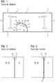
- FIG 1 shows a rail vehicle 1 with a car door 20 of the prior art.
- Figures 2 and 3 two examples of a closed state of the car door 20 of the prior art are shown.
- the Figures 4 and 5 show a detailed view of the car door 20 in the open ( Figure 4 ) and closed state ( Figure 5 )
- the rail vehicle 1 comprises, for example, at least two wheel sets 5 which are arranged on the underside of the rail vehicle.
- the rail vehicle 1 also comprises a plurality of doors 3 for getting on and off the vehicle 1, the doors being arranged in the outer shell 7 of the vehicle 1.
- a cabin 10 is arranged inside the vehicle 1.
- the cabin 10 comprises a cabin wall 14, an opening 12 in the cabin wall and a door 20 for opening and closing the opening 12.
- the cabin 10 can therefore be entered or left through the door 20.
- the door 20 comprises a door leaf 30 which is designed concentrically. The door rotates around a pivot point 40 on a section of a circular path for opening and closing. In the closing direction 42 of the door 20, the cabin wall 14 has a door stop 16.
- the door stop 16 is delimited by an outer area 18 and an inner area 17 of the cabin wall 14.
- door stop 16, outer area 18 and inner area 17 form a triangular structure.
- the cabin wall 14 also has a concentric section 15 in the area of the door leaf 30, corresponding to the shape of the door leaf 30. In the open state, the concentric section 15 and door leaf 30 are parallel to one another.
- FIG Figure 2 shows a closing edge 24 of the car door 20 with the door leaf 30, which lies plane-parallel against the door stop 16. No gap is formed, the door 20 is properly closed.
- complex adjustments of the concentric door guidance are necessary in order to ensure that the door 20 runs smoothly.
- These complex settings can arise, for example, due to tolerances or a bracing of the cabin 10 in the installed state.
- the door 20 is closed incorrectly. It is then possible, in an undesired manner, to look into the actually closed cabin 10 through this gap 19. This is particularly undesirable in the case of cabins 10 which house a sanitary area.
- the door stop 16 can be formed by a type of pocket into which the door leaf 30 runs in frontally in the closed state, following the circumference of the circular path. This is in the Figures 4 and 5 shown.
- the pocket function entails an increased risk of pinching fingers and hands, especially for children, and can only compensate for small tolerances with regard to the vertical gap 19 in the currently known designs.
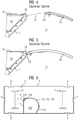
- Figure 6 shows a cabin door 120 according to the invention in a vehicle 1.
- Figure 7 shows the car 110 with the car door 120 in an enlarged view.
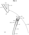
- the Figures 8 and 9 show the door 120 according to the invention in detailed views, once during the closing process ( Figure 8 ) and once after closing the door 120 ( Figure 9 ).
- the cabin 110 in turn comprises a cabin wall 114 with a concentric wall segment 115, which is arranged parallel to a concentric segment 132 of the door leaf 130 of the door 120. At least when the door 120 is open, the concentric wall segment 115 and the concentric door leaf segment 132 overlap.
- the cabin wall 114 in turn has a door stop 116 which, as in FIG Figure 1 shown is delimited by an inner area 117 and an outer area 118 of the cabin wall 114.
- Door stop 116, inner area 117 and outer area 118 form a triangular structure.
- the door 120 rotates about a pivot point 140 and in the closing direction 142 has a free end 134 - 2 which forms the closing edge 124 of the door 120.
- the concentric segment 132 of the door leaf 130 is adjoined in the closing direction 142 of the door 120 by a linear segment 134 which is connected to the concentric segment 132 with a fixed end 134-1 in a form-fitting manner.
- the linear segment 134 preferably connects seamlessly to the narrow edge of the concentric element 132.
- Concentric and linear segments 132, 134 preferably have the same thickness and height.
- the closing edge 124 of the door 120 lies against the door stop 116 in a form-fitting manner.
- the door stop 116 is preferably as in FIG Fig. 6 shown as a straight edge which connects the inner area 117 to the outer area 118 of the cabin wall 114.
- the linear segment 134 is curved away from the circular path outward. In other words, the distance a1 from the fixed end 134-1 of the linear segment 134 to the pivot point 140 is less than the distance a2 from the free end 134-2 to the pivot point 140.
- Concentric segment 132 and linear segment 134 can be made from the same material or from different materials.
- the linear segment can be designed to be elastic at least on its closing edge 124 in order to alleviate the trapping of hands between the closing edge 124 and door stop 116 and to absorb a contact pressure for better closing of the door 120.
- the closing edge of a simply curved door leaf is therefore supplemented with an outwardly bent, straight section. This results in a combined rotational, translational relative movement between the closing edge of the door leaf and the door stop. This is easier to control.
- the Figures 8 and 9 show detailed views of the process of closing the door 120.
- the door is not closed yet, in Figure 9 the door is in the closed state.
- the door initially closes in a rotary manner (right) and then in a translatory manner (left).
- the linear door segment 134 preferably has an end profile 150 at its free end 134-2.
- a suitable end profile 150 for example a rubber profile, a generous covering of gaps resulting from inclined positions of the door leaf 130 can be achieved.
- the closing profile 152 preferably extends over the entire externally visible height of the door 120. It is thus designed such that, when the door 120 is closed, in the outer area 118 of the opening 112 of the door 120, the transition between the closing edge 124 and door stop 116 is horizontal and vertical completely covers.
- the end profile 150 overlaps with the outer region 118 of the cabin wall 114 in such a way that possible gaps are covered from the outside due to adjustments. A generous covering of gaps resulting from inclined positions of the door leaf 130 can therefore be achieved by the end profile 150. At the same time, trapping of hands can be excluded. A large distance can be realized between the rigid components of the door leaf 130 and the door stop 116, since the elastic, soft end profile 150 closes the gap.
- the closing profile 150 rests against the outer region 118 of the cabin wall 114; on the other hand, it is preferably formed between the closing edge 124 and door stop 114. This allows the linear kinetic energy to be absorbed during the last section of the closing process of the door 120.
- an end profile 150 makes it easier to adjust the door during initial installation and during maintenance. This saves time during installation and maintenance, since the setting only needs to be aimed at the running properties during opening and closing.
- the end profile 150 with two linear partial areas 152 is pushed onto the free end 134 - 2 of the linear segment 134. This enables simple assembly and disassembly of the end profile 150. However, it can also be glued or otherwise fastened.
- the end profile 150 has a first elastic element 154 which is designed to absorb a linear force between the door stop 116 and the free end 134-1. Shown by way of example, the first elastic element 154 has a nose-like or hook-like shape. The first elastic element is compressed in the direction of the free end 134-1 when the door 120 is closed.
- the end profile 150 has a second elastic element 156, which from the outside rests against the outer region 118 of the car door 120.
- the second elastic element 156 has the shape of a lip. When the door 120 is closed, the lip is bent straight to lie against the outer region 118 of the cabin wall 114 around the opening 112.
- the end profile 150 can be designed in one piece as an elastic element or also consist of at least two separate first and second elastic elements 154, 156.
- the elastic element can also be arranged rotatably around a pivot point 158 at the free end 134 - 1 of the linear segment 134. This can enable an even better form fit between the end profile 150 and the outer area 118 of the cabin wall 114.
- the rotatable closing profile 150 can then preferably be directed in the direction of the outer region 118 be arranged preloaded so that the rotation can only be carried out against a spring force.
Landscapes
- Engineering & Computer Science (AREA)
- Mechanical Engineering (AREA)
- Health & Medical Sciences (AREA)
- Epidemiology (AREA)
- General Health & Medical Sciences (AREA)
- Public Health (AREA)
- Civil Engineering (AREA)
- Structural Engineering (AREA)
- Body Structure For Vehicles (AREA)
- Specific Sealing Or Ventilating Devices For Doors And Windows (AREA)
- Window Of Vehicle (AREA)
- Component Parts Of Construction Machinery (AREA)
Description
- Die Erfindung betrifft eine Kabine, die durch eine dreh- bzw. schwenkbare Tür betreten werden kann sowie ein Fahrzeug mit einer solchen Kabine.
- In Fahrzeugen, insbesondere in Schienenfahrzeugen im Nah- und Fernverkehr, werden behindertengerechte Universaltoiletten in Form von Kabinen eingesetzt, die in den meisten Fällen durch eine sich auf einer Kreisbahn bewegende, ggfs. auch automatisch betriebene Schiebetür, betreten werden. Aufgrund von Justierungen kann das Türblatt jedoch aus seiner eigentlich lotrechten Ausrichtung zum Kabinenboden gezwungen werden, was am Türanschlag zu unerwünschten Spalten führen kann. Durch diese Spalte hindurch kann dann unerwünschterweise Einblick in die eigentlich geschlossene Kabine genommen werden.
- Zur Verhinderung der einstellungsbedingten Spalte kann der Türanschlag durch eine Art Tasche gebildet werden, in die das Türblatt im schließenden Zustand, dem Umfang der Kreisbahn folgend, frontal einläuft. Dadurch können kleine Schiefstellungen des Türblattes abgefangen werden. Die Taschenfunktion birgt jedoch aufgrund der Scherwirkung ein erhöhtes Klemmrisiko für Finger und Hände, speziell für Kinder und kann in den derzeitig bekannten Bauausführungen nur geringe Toleranzen bezüglich der vertikalen Spalte ausgleichen. Beim Schließen der Tür kommt es aufgrund der rein rotatorischen Bewegung zu einer frontalen Annäherung zwischen Schließkante des Türblattes und Türanschlag.
-
EP 2 705 997 A1 lehrt eine Kabine eines Fahrzeugs mit einer teilweise kreisbogenförmig verlaufenden Kabinenwand. - Die Aufgabe besteht darin, eine einfachere Justierung einer sich drehende Tür zu ermöglichen. Ferner besteht die Aufgabe darin, das Schließen der Tür sicherer zu gestalten.
- Erfindungsgemäß wird eine Kabine für ein Fahrzeug zur Verfügung gestellt, wobei die Kabine mit einer Öffnung in einer Kabinenwand ausgebildet ist. Ferner ist eine Tür zum Öffnen und Schließen der Öffnung vorgesehen, wobei sich die Tür um einen Drehpunkt herum bewegt und ein bewegliches Türblatt umfasst, welches ein konzentrisches Segment aufweist. Die Kabinenwand bildet zudem in Schließrichtung der Tür einen Türanschlag aus. Erfindungsgemäß weist das Türblatt ferner ein lineares Segment mit einem festen Ende und einem freien Ende auf, wobei das lineare Segment an seinem festen Ende in Schließrichtung der Tür an das konzentrische Segment anschließt. Das freie Ende des linearen Segments bildet in Schließrichtung der Tür des Türblattes eine Schließkante aus, die im geschlossenen Zustand der Tür am Türanschlag anliegt.
- Diese Ausbildung des Türblattes mit einem zusätzlichen linearen Endsegment hat den Vorteil, dass die sich drehende Tür translatorisch am Türanschlag anschlägt. Diese translatorische Bewegung ist einfacher zu justieren gegenüber einer rein rotatorischen Bewegung. Zudem ist für einen Benutzer zum Vermeiden des Einklemmens von Fingern eine translatorische Bewegung leichter nachzuvollziehen als eine rotatorische Bewegung und es treten keine Scherkräfte auf.
- Der Abstand des festen Endes zum Drehpunkt ist dabei geringer als der Abstand des freien Endes zum Drehpunkt. Mit anderen Worten ist das lineare Segment bezüglich der Kreisbahn nach außen weggebogen angeordnet. Dies erlaubt es, dass sich das Türblatt beim Schließen der Tür auf den Türanschlag zubewegt.
- Am freien Ende des linearen Segmentes des Türblatts ist vorteilhafterweise ein elastisches Abschlussprofil angeordnet. Das Abschlussprofil liegt bevorzugt im geschlossenen Zustand der Tür an der Kabinenwand im Bereich der Öffnung von außen an. In einem bevorzugten Ausführungsbeispiel ist das Abschlussprofil derart angeordnet, dass es im geschlossenen Zustand der Tür die Schließkante der Tür und den Türanschlag von außen abdeckt, bevorzugt vollständig abdeckt. Bevorzugt liegt das Abschlussprofil am Türanschlag der Tür anliegt.
- Durch das Abschlussprofil kann eine großzügige Abdeckung von aus Schiefstellungen des Türblattes resultierenden Spalten erreicht werden. Gleichzeitig kann ein Einklemmen von Händen ausgeschlossen werden. Da das elastische, weiche Abschlussprofil einen Lückenschluss herstellt kann ein großer Abstand zwischen den starren Bauteilen des Türblatts und des Türanschlags realisiert werden. Ferner wird die Quetschgefahr durch Bedeckung des Anschlags weiter vermindert.
- Vorteilhafterweise ergibt sich durch die Verwendung eines Abschlussprofils eine einfachere Justierung der Tür beim Ersteinbau und während der Wartung. Dies führt zu einer Zeitersparnis beim Einbau und der Wartung, da die Einstellung nur auf die Laufeigenschaften beim Öffnen und Schließen abzielen muss.
- Zudem ist ein Kompromiss aus Laufruhe und optischer Ausrichtung bezüglich des Schließspaltmaßes aufgrund der großen Überdeckung von Abschlussprofil und Wandanschlag nicht notwendig, da es keinen sichtbaren, senkrechten Spalt gibt. Es fehlt somit ein Orientierungspunkt zum Erkennen einer vertikalen Fehlstellung.
- Bevorzugt erstreckt sich das Abschlussprofil über die gesamte Höhe des von außen sichtbaren Türblattes. Dies ermöglicht eine vollständige Abdeckung lediglich des sichtbaren Bereichs des Türanschlags. Der nicht sichtbare Bereich, welcher im Boden oder in der Decke der Kabine verlaufen kann, benötigt dann kostensparend kein Abschlussprofil.
- In einem bevorzugten Ausführungsbeispiel besteht das Abschlussprofil zumindest in Teilen aus Gummi oder Silikon. Dies ermöglicht eine besonders einfache Realisierung des Abschlussprofils.
- Das Abschlussprofil kann ein erstes elastisches Element aufweisen, welches im geschlossenen Zustand der Tür zwischen freiem Ende der Tür und Türanschlag anliegt. Das erste elastische Element kann als elastische Nase, z.B. eine Gumminase ausgebildet sein. Das Abschlussprofil kann ein zweites elastisches Element aufweisen, welches im geschlossenen Zustand der Tür von Außen an der Kabinenwand anliegt. Das zweite elastische Element kann als elastische Lippe ausgebildet sein. Dies ermöglicht es, nur Teile des Abschlussprofils elastisch auszubilden und verschiedene Toleranzen unterschiedlich elastisch aufzufangen.
- Die Länge des linearen Segments beträgt weniger als 10%, bevorzugt weniger als 5% der Länge des konzentrischen Segments. Es wird daher nur ein bezüglich der Drehbewegung kleines Endstück durch ein lineares Endsegment ersetzt.
- Ferner ist ein Fahrzeug umfassend eine Fahrzeughülle und eine in der Fahrzeughülle angeordnete erfindungsgemäße Kabine vorgesehen.
- Das Fahrzeug ist bevorzugt ein motorbetriebenes Fahrzeug, besonders bevorzugt ein Schienenfahrzeug. Insbesondere bei Schienenfahrzeugen können entsprechende Kabinentüren, z.B. für den Sanitärbereich, vorgesehen sein. Das Fahrzeug umfasst auch andere Verkehrsmittel, wie zum Beispiel Busse, Schiffe und Flugzeuge. Auch dort können Kabinen, z.B. Sanitärbereiche, mittels der erfindungsgemäßen Tür verschlossen werden.
- Die erfindungsgemäße Kabinentür kann sowohl manuell als auch automatisch betrieben werden.
- Die oben beschriebenen Eigenschaften, Merkmale und Vorteile dieser Erfindung sowie die Art und Weise, wie diese erreicht werden, werden klarer und deutlicher verständlich im Zusammenhang mit der folgenden Beschreibung der Ausführungsbeispiele, die im Zusammenhang mit den Zeichnungen näher erläutert werden. Es zeigen:
- Figur 1
- ein Fahrzeug mit einer Kabinentür des Standes der Technik,
- Figur 2
- eine korrekt geschlossene Kabinentür des Standes der Technik,
- Figur 3
- eine fehlerhaft geschlossene Kabinentür des Standes der Technik,
- Figur 4
- eine Detailansicht der Kabinentür des Standes der Technik im geöffneten Zustand,
- Figur 5
- eine Detailansicht der Kabinentür des Standes der Technik im geschlossenen Zustand,
- Figur 6
- ein Fahrzeug mit einer erfindungsgemäßen Kabinentür,
- Figur 7
- eine erfindungsgemäße Kabinentür für ein Fahrzeug, und
- Figur 8
- eine Detailansicht einer erfindungsgemäßen Kabinentür für ein Fahrzeug im geöffneten Zustand.
- Figur 9
- eine Detailansicht einer erfindungsgemäßen Kabinentür für ein Fahrzeug im geschlossenen Zustand.
- Die Erfindung betrifft eine Kabinentür für ein Fahrzeug. Im Folgenden wird die Kabinentür beispielhaft in einem Schienenfahrzeug angeordnet gezeigt und erläutert werden. Sie kann aber auch in anderen Fahrzeugen wie Bussen, Schiffen und Flugzeugen angeordnet sein.
- Beispielhaft kann die erfindungsgemäße Kabine einen Sanitärbereich beherbergen. Sie kann aber auch eine Personenkabine mit Sitz- oder Liegeplätzen sein.
- In der
Figur 1 ist ein Schienenfahrzeug 1 mit einer Kabinentür 20 des Standes der Technik gezeigt. In denFiguren 2 und 3 sind zwei Beispiele eines geschlossenen Zustandes der Kabinentür 20 des Standes der Technik gezeigt. DieFiguren 4 und 5 zeigen eine Detailansicht der Kabinentür 20 im geöffneten (Figur 4 ) und geschlossenen Zustand (Figur 5 ) - Das Schienenfahrzeug 1 umfasst beispielhaft mindestens zwei Radsätze 5, die an der Unterseite des Schienenfahrzeugs angeordnet sind. Das Schienenfahrzeug 1 umfasst zudem mehrere Türen 3 zum Besteigen und Verlassen des Fahrzeugs 1, wobei die Türen in der Außenhülle 7 des Fahrzeugs 1 angeordnet sind. Im Inneren des Fahrzeugs 1 ist eine Kabine 10 angeordnet. Die Kabine 10 umfasst eine Kabinenwand 14, eine Öffnung 12 in der Kabinenwand und eine Tür 20 zum Öffnen und Schließen der Öffnung 12. Die Kabine 10 kann also durch die Tür 20 betreten oder verlassen werden. Die Tür 20 umfasst ein Türblatt 30, welches konzentrisch ausgebildet ist. Die Tür dreht sich zum Öffnen und Schließen auf einem Abschnitt einer Kreisbahn um einen Drehpunkt 40 herum. In Schließrichtung 42 der Tür 20 weist die Kabinenwand 14 einen Türanschlag 16 auf. Der Türanschlag 16 wird von einem Außenbereich 18 und einem Innenbereich 17 der Kabinenwand 14 begrenzt. Im gezeigten Ausführungsbeispiel bilden Türanschlag 16, Außenbereich 18 und Innenbereich 17 eine dreieckige Struktur aus. Auch die Kabinenwand 14 weist im Bereich des Türblattes 30 einen konzentrischen Abschnitt 15 auf, entsprechend der Form des Türblattes 30. Im geöffneten Zustand liegen konzentrischer Abschnitt 15 und Türblatt 30 parallel zueinander.
-
Figur 2 zeigt eine Schließkante 24 der Kabinentür 20 mit dem Türblatt 30, welche planparallel an dem Türanschlag 16 anliegt. Es bildet sich kein Spalt, die Tür 20 ist korrekt geschlossen. Bei der gezeigten Kabine 10 mit einer Tür 20 des Standes der Technik sind jedoch, um einen störungsfreien Lauf der Tür 20 zu gewährleisten, aufwendige Einstellungen der konzentrischen Türführung nötig. Diese aufwendigen Einstellungen können sich beispielsweise aufgrund von Toleranzen oder einer Verspannung der Kabine 10 im eingebauten Zustand ergeben. Durch diese notwendigen Einstellungen kann das Türblatt 30 aus seiner eigentlich lotrechten Ausrichtung zum Kabinenboden gezwungen werden, was am Türanschlag 16 zu unerwünschten Spalten 19 führen kann, wie inFigur 3 gezeigt. Die Tür 20 ist fehlerhaft geschlossen. Durch diese Spalte 19 hindurch kann dann unerwünschterweise Einblick in die eigentlich geschlossene Kabine 10 genommen werden. Dies ist insbesondere bei Kabinen 10, die einen Sanitärbereich beherbergen, nicht erwünscht. - Zur Verhinderung der einstellungsbedingten Spalte 19 kann der Türanschlag 16 durch eine Art Tasche gebildet werden, in die das Türblatt 30 im schließenden Zustand, dem Umfang der Kreisbahn folgend, frontal einläuft. Dies ist in den
Figuren 4 und 5 gezeigt. In Folge können kleine Schiefstellungen des Türblattes 30 in Bezug auf Sichtspalte 19 abgefangen werden. Die Taschenfunktion birgt jedoch aufgrund der Scherwirkung ein erhöhtes Klemmrisiko für Finger und Hände, speziell für Kinder und kann in den derzeitig bekannten Bauausführungen nur geringe Toleranzen bezüglich der vertikalen Spalte 19 ausgleichen. Beim Schließen der Tür 20 kommt es aufgrund der rein rotatorischen Bewegung zu einer frontalen Annäherung zwischen Schließkante 24 des Türblattes 20 und Türanschlag 16. -
Figur 6 zeigt einen erfindungsgemäße Kabinentür 120 in einem Fahrzeug 1.Figur 7 zeigt die Kabine 110 mit der Kabinentür 120 in vergrößerter Ansicht. DieFiguren 8 und9 zeigen die erfindungsgemäße Tür 120 in Detailansichten, einmal während des Schließvorganges (Figur 8 ) und einmal nach Schließen der Tür 120 (Figur 9 ). - Die Kabine 110 umfasst wiederum eine Kabinenwand 114 mit einem konzentrischen Wandsegment 115, welches parallel zu einem konzentrischen Segment 132 des Türblattes 130 der Tür 120 angeordnet ist. Zumindest im geöffneten Zustand der Tür 120 überlappen sich das konzentrische Wandsegment 115 und des konzentrische Türblattsegment 132. Die Kabinenwand 114 weist wiederum einen Türanschlag 116 aus, der wie in
Figur 1 gezeigt von einem Innenbereich 117 und einem Außenbereich 118 der Kabinenwand 114 begrenzt wird. Türanschlag 116, Innenbereich 117 und Außenbereich 118 bilden eine Dreiecksstruktur aus. - Die erfindungsgemäße Tür 120 dreht sich um einen Drehpunkt 140 und weist in Schließrichtung 142 ein freies Ende 134-2 auf, welches die Schließkante 124 der Tür 120 ausbildet. An das konzentrische Segment 132 des Türblattes 130 schließt sich in Schließrichtung 142 der Tür 120 ein lineares Segment 134 an, welches mit einem festen Ende 134-1 formschlüssig mit dem konzentrischen Segment 132 verbunden ist. Das lineare Segment 134 schließt bevorzugt an die schmale Kante des konzentrischen Elementes 132 nahtlos an. Konzentrisches und lineares Segment 132, 134 haben bevorzugt dieselbe Dicke und dieselbe Höhe.
- Im geschlossenen Zustand der Tür 120 liegt die Schließkante 124 der Tür 120 formschlüssig an dem Türanschlag 116 an. Der Türanschlag 116 ist bevorzugt wie in
Fig. 6 gezeigt als gerade Kante ausgebildet, die den Innerbereich 117 mit dem Außenbereich 118 der Kabinenwand 114 verbindet. Das lineare Segment 134 ist von der Kreisbahn nach außen weggebogen ausgebildet. Mit anderen Worten, der Abstand a1 des festen Endes 134-1 des linearen Segments 134 zum Drehpunkt 140 ist geringer als der Abstand a2 des freien Endes 134-2 zum Drehpunkt 140. - Konzentrisches Segment 132 und lineares Segment 134 können aus demselben Material oder aus unterschiedlichen Materialien gefertigt sein. So kann z.B. das lineare Segment zumindest an seiner Schließkante 124 elastisch ausgebildet sein, um ein Einklemmen von Händen zwischen Schließkante 124 und Türanschlag 116 abzumildern und einen Anpressdruck zum besseren Verschließen der Tür 120 aufzunehmen.
- Erfindungsgemäß wird demnach die Schließkante eines einfach gebogenen Türblattes mit einem nach außen geknickten, geraden Teilstück ergänzt. Dadurch kommt es zwischen der Schließkante des Türblattes und dem Türanschlag zu einer kombinierten rotatorisch translatorischen Relativbewegung. Diese ist einfacher zu kontrollieren.
- Die
Figuren 8 und9 zeigen Detailansichten des Vorgangs des Schließens der Tür 120. InFigur 8 ist die Tür noch nicht geschlossen, inFigur 9 befindet sich die Tür im geschlossenen Zustand. Die Tür schließt zunächst rotatorisch (rechts) und abschließend translatorisch (links). Bevorzugt weist das lineare Türsegment 134 ein Abschlussprofil 150 an seinem freien Ende 134-2 auf. Durch die Wahl eines geeigneten Abschlussprofils 150, z.B. eines Gummiprofils, kann eine großzügige Abdeckung von aus Schiefstellungen des Türblattes 130 resultierenden Spalten erreicht werden. Das Abschlussprofil 152 erstreckt sich bevorzugt über die gesamte von außen sichtbare Höhe der Tür 120. Es ist somit so ausgebildet, dass es im geschlossenen Zustand der Tür 120 im Außenbereich 118 der Öffnung 112 der Tür 120 den Übergang Schließkante 124 und Türanschlag 116 horizontal und vertikal vollständig abdeckt. Hierbei überlappt das Abschlussprofil 150 mit dem Außenbereich 118 der Kabinenwand 114 derart, dass mögliche Spalte aufgrund von Justierungen von Außen abgedeckt werden. Durch das Abschlussprofil 150 kann also eine großzügige Abdeckung von aus Schiefstellungen des Türblattes 130 resultierenden Spalten erreicht werden. Gleichzeitig kann ein Einklemmen von Händen ausgeschlossen werden. Es kann ein großer Abstand zwischen den starren Bauteilen des Türblatts 130 und des Türanschlags 116 realisiert werden, da das elastische, weiche Abschlussprofil 150 einen Lückenschluss herstellt. Das Abschlussprofil 150 liegt zum einen an dem Außenbereich 118 der Kabinenwand 114 an, zum anderen ist es bevorzugt zwischen Schließkante 124 und Türanschlag 114 ausgebildet. Dies erlaubt eine Aufnahme der linearen Bewegungsenergie während des letzten Abschnittes des Schließvorgangs der Tür 120. - Durch die Verwendung eines Abschlussprofils 150 kann eine einfachere Justierung der Tür beim Ersteinbau und während der Wartung erzielt werden. Dies führt zu einer Zeitersparnis beim Einbau und der Wartung, da die Einstellung nur auf die Laufeigenschaften beim Öffnen und Schließen abzielen muss.
- Im gezeigten Ausführungsbeispiel das Abschlussprofil 150 mit zwei linearen Teilbereichen 152 auf das freie Ende 134-2 des linearen Segments 134 aufgesteckt. Dies ermöglicht eine einfache Montage und Demontage des Abschlussprofils 150. Es kann aber auch festgeklebt oder anders befestigt werden. Zwischen Türanschlag 116 und freiem Ende 134-1 weist das Abschlussprofil 150 ein erstes elastische Element 154 auf, welches dazu ausgebildet ist, eine lineare Kraft zwischen Türanschlag 116 und freiem Ende 134-1 aufzunehmen. Beispielhaft gezeigt weist das erste elastische Element 154 eine nasen- oder hakenähnliche Form auf. Das erste elastische Element wird in Richtung des freien Endes 134-1 beim Schließen der Tür 120 zusammengedrückt. Ferner weist das Abschlussprofil 150 ein zweites elastisches Element 156 auf, welches von Außen am Außenbereich 118 der Kabinentür 120 anliegt. Beispielhaft weist das zweite elastische Element 156 die Form einer Lippe auf. Die Lippe wird beim Schließen der Tür 120 gerade gebogen um an dem Außenbereich 118 der Kabinenwand 114 um die Öffnung 112 herum anzuliegen.
- Das Abschlussprofil 150 kann einstückig als elastisches Element ausgebildet sein oder auch aus mindestens zwei getrennten ersten und zweiten elastischen Elementen 154, 156 bestehen.
- Ferner kann das elastische Element auch drehbar um einen Drehpunkt 158 herum am freien Ende 134-1 des linearen Segments 134 angeordnet sein. Dies kann einen noch besseren Formschluss zwischen Abschlussprofil 150 und Außenbereich 118 der Kabinenwand 114 ermöglichen. Bevorzugt kann das drehbare Abschlussprofil 150 dann in Richtung des Außenbereichs 118 vorgespannt angeordnet sein, so dass die Drehung nur entgegen einer Federkraft ausführbar ist.
- Obwohl die Erfindung im Detail durch bevorzugte Ausführungsbeispiele näher illustriert und beschrieben wurde, so ist die Erfindung nicht durch die offenbarten Beispiele eingeschränkt und andere Variationen können vom Fachmann hieraus abgeleitet werden, ohne den Schutzumfang der Erfindung zu verlassen.
Claims (12)
- Eine Kabine (110) für ein Fahrzeug (1) umfassend:eine Kabinenwand (144) mit einer Öffnung (112),eine Tür (120) zum Öffnen und Schließen der Öffnung (112), wobei sich die Tür (120) um einen Drehpunkt (140) herum bewegt und ein bewegliches Türblatt (130) umfasst, welches ein konzentrisches Segment (132) aufweist und die Kabinenwand (114) in Schließrichtung (142) der Tür (120) einen Türanschlag (116) ausbildet,dadurch gekennzeichnet, dassdas Türblatt (130) ferner ein lineares Segment (134) mit einem festen Ende (134-1) und einem freien Ende (134-2) aufweist,wobei sich das lineare Segment (134) an seinem festen Ende (134-1) in Schließrichtung (142) der Tür (120) an das konzentrische Segment (132) anschließt,das freie Ende (134-2) in Schließrichtung (142) der Tür (120) des Türblattes (130) eine Schließkante (124) ausbildet, die im geschlossenen Zustand der Tür (120) am Türanschlag (116) anliegt.
- Kabine (110) nach Anspruch 1, wobei der Abstand (a1) des festen Endes (134-1) zum Drehpunkt (140) geringer ist als der Abstand (a2) des freien Endes (a2) zum Drehpunkt (140).
- Kabine (110)nach Anspruch 1 oder 2, wobei am freien Ende (134-2) des linearen Segmentes (134) des Türblatts (130) ein elastisches Abschlussprofil (150) angeordnet ist.
- Kabine (110) nach Anspruch 3, wobei das Abschlussprofil (150) im geschlossenen Zustand der Tür (120) an der Kabinenwand (118) im Bereich der Öffnung (112) von außen anliegt.
- Kabine (110) nach einem der Ansprüche 3 oder 4, wobei das Abschlussprofil (150) derart angeordnet ist, dass es im geschlossenen Zustand der Tür die Schließkante (124) der Tür (120) und den Türanschlag (116) von außen abdeckt, bevorzugt vollständig abdeckt.
- Kabine (110) nach einem der Ansprüche 3 bis 5, wobei das Abschlussprofil (150) am Türanschlag (116) der Tür (120) anliegt.
- Kabine (110) nach einem der Ansprüche 3 bis 6, wobei das Abschlussprofil (150) ein erstes elastisches Element (154) aufweist, welches im geschlossenen Zustand der Tür (120) zwischen freiem Ende (134-2) der Tür (120) und Türanschlag (116) anliegt.
- Kabine (110) nach Anspruch 7, wobei das erste elastische Element (154) als elastische Nase ausgebildet ist.
- Kabine (110) nach einem der Ansprüche 3 bis 8, wobei das Abschlussprofil (150) ein zweites elastisches Element (156) aufweist, welches im geschlossenen Zustand der Tür (120) von Außen an der Kabinenwand (116) anliegt.
- Kabine (110) nach Anspruch 9, wobei das zweite elastische Element (156) als elastische Lippe ausgebildet ist.
- Kabine (110) nach einem der vorhergehenden Ansprüche, wobei die Länge des linearen Segments (134) weniger als 10%, bevorzugt weniger als 5% der Länge des konzentrischen Segments (132) umfasst.
- Fahrzeug (1) umfassend eine Fahrzeughülle (7) und eine in der Fahrzeughülle (7) angeordnete Kabine (110) nach einem der Ansprüche 1 bis 11.
Priority Applications (1)
| Application Number | Priority Date | Filing Date | Title |
|---|---|---|---|
| PL16717903T PL3259166T3 (pl) | 2015-04-30 | 2016-04-18 | Kabina z obrotowymi drzwiami kabiny do pojazdu |
Applications Claiming Priority (2)
| Application Number | Priority Date | Filing Date | Title |
|---|---|---|---|
| DE102015208075.7A DE102015208075A1 (de) | 2015-04-30 | 2015-04-30 | Kabine mit drehbarer Kabinentür für ein Fahrzeug |
| PCT/EP2016/058563 WO2016173878A1 (de) | 2015-04-30 | 2016-04-18 | Kabine mit drehbarer kabinentür für ein fahrzeug |
Publications (2)
| Publication Number | Publication Date |
|---|---|
| EP3259166A1 EP3259166A1 (de) | 2017-12-27 |
| EP3259166B1 true EP3259166B1 (de) | 2020-08-26 |
Family
ID=55806326
Family Applications (1)
| Application Number | Title | Priority Date | Filing Date |
|---|---|---|---|
| EP16717903.5A Active EP3259166B1 (de) | 2015-04-30 | 2016-04-18 | Kabine mit drehbarer kabinentür für ein fahrzeug |
Country Status (10)
| Country | Link |
|---|---|
| US (1) | US10703391B2 (de) |
| EP (1) | EP3259166B1 (de) |
| CN (1) | CN208959330U (de) |
| DE (1) | DE102015208075A1 (de) |
| DK (1) | DK3259166T3 (de) |
| ES (1) | ES2833367T3 (de) |
| PL (1) | PL3259166T3 (de) |
| PT (1) | PT3259166T (de) |
| RU (1) | RU184300U1 (de) |
| WO (1) | WO2016173878A1 (de) |
Cited By (1)
| Publication number | Priority date | Publication date | Assignee | Title |
|---|---|---|---|---|
| EP4116168A1 (de) | 2021-07-09 | 2023-01-11 | Bombardier Transportation GmbH | Selbstschliessende türanordnung einer schiebetür, toilettenkabine für ein schienenfahrzeug und selbstschliessender türbausatz |
Families Citing this family (3)
| Publication number | Priority date | Publication date | Assignee | Title |
|---|---|---|---|---|
| DE102015208075A1 (de) * | 2015-04-30 | 2016-11-03 | Siemens Aktiengesellschaft | Kabine mit drehbarer Kabinentür für ein Fahrzeug |
| FR3040031B1 (fr) * | 2015-08-14 | 2017-09-15 | Alstom Transp Tech | Cabine de toilettes pour vehicule de transport public, destinee a accueillir une personne a mobilite reduite |
| US12320174B2 (en) * | 2021-05-17 | 2025-06-03 | Inventio Ag | Sliding door system for installing into a building wall, and method for servicing a sliding door system |
Family Cites Families (14)
| Publication number | Priority date | Publication date | Assignee | Title |
|---|---|---|---|---|
| US2587868A (en) * | 1947-09-03 | 1952-03-04 | Youngstown Steel Door Co | Watertight edge for railway car doors |
| SU125150A1 (ru) | 1959-04-03 | 1959-11-30 | М.М. Касенков | Светомаскировочна насадка на фары машин |
| DE4336418C2 (de) * | 1993-10-19 | 2001-05-31 | Daimler Chrysler Ag | Sanitärzellensystem, insbesondere für Schienenfahrzeuge |
| DE19913318A1 (de) | 1998-07-06 | 2000-01-13 | Konrad Weinhuber | WC-Zelle für Behinderte |
| DE29817742U1 (de) | 1998-10-05 | 2000-02-17 | Staudenmayer GmbH, 73084 Salach | WC-Kabine für Eisenbahnwaggons |
| AT501468B8 (de) * | 2005-02-17 | 2007-02-15 | Knorr Bremse Gmbh | Schwenkschiebetür |
| DE102005055758B4 (de) | 2005-11-21 | 2010-07-01 | Satek Gmbh | Sanitärkabine in Modulbauweise |
| DE102007007624B4 (de) | 2007-02-13 | 2008-10-30 | Maschinenbau Und Service Gmbh Ammendorf | Sanitär- bzw. WC-Modul, insbesondere für Fahrzeuge |
| FR2935946B1 (fr) | 2008-09-18 | 2010-10-29 | Sncf | Bloc de compartiment de toilettes |
| DE102008062462A1 (de) | 2008-12-16 | 2010-06-17 | Rcs Gmbh Rail Components And Systems | Grundkörper einer Nasszelle für Reisezüge |
| DE102012108469B4 (de) * | 2012-09-11 | 2018-09-20 | Bombardier Transportation Gmbh | Schienenfahrzeug mit einer Sanitärzelle, sowie Verfahren zur Herstellung einer Sanitärzelle für ein Schienenfahrzeug |
| DE102014217343A1 (de) * | 2014-08-29 | 2016-03-03 | Siemens Aktiengesellschaft | Schiebetür |
| DE102015208075A1 (de) * | 2015-04-30 | 2016-11-03 | Siemens Aktiengesellschaft | Kabine mit drehbarer Kabinentür für ein Fahrzeug |
| DE102016013797A1 (de) * | 2016-11-21 | 2018-05-24 | Knorr-Bremse Gesellschaft Mit Beschränkter Haftung | Türmodul zur Anordnung in einer Türöffnung eines Wagenkastens eines Fahrzeugs |
-
2015
- 2015-04-30 DE DE102015208075.7A patent/DE102015208075A1/de not_active Withdrawn
-
2016
- 2016-04-18 RU RU2017141060U patent/RU184300U1/ru active
- 2016-04-18 US US15/570,452 patent/US10703391B2/en active Active
- 2016-04-18 ES ES16717903T patent/ES2833367T3/es active Active
- 2016-04-18 DK DK16717903.5T patent/DK3259166T3/da active
- 2016-04-18 EP EP16717903.5A patent/EP3259166B1/de active Active
- 2016-04-18 CN CN201690000772.8U patent/CN208959330U/zh not_active Expired - Lifetime
- 2016-04-18 PL PL16717903T patent/PL3259166T3/pl unknown
- 2016-04-18 PT PT167179035T patent/PT3259166T/pt unknown
- 2016-04-18 WO PCT/EP2016/058563 patent/WO2016173878A1/de not_active Ceased
Non-Patent Citations (1)
| Title |
|---|
| None * |
Cited By (1)
| Publication number | Priority date | Publication date | Assignee | Title |
|---|---|---|---|---|
| EP4116168A1 (de) | 2021-07-09 | 2023-01-11 | Bombardier Transportation GmbH | Selbstschliessende türanordnung einer schiebetür, toilettenkabine für ein schienenfahrzeug und selbstschliessender türbausatz |
Also Published As
| Publication number | Publication date |
|---|---|
| US20180148073A1 (en) | 2018-05-31 |
| CN208959330U (zh) | 2019-06-11 |
| WO2016173878A1 (de) | 2016-11-03 |
| PL3259166T3 (pl) | 2021-02-08 |
| US10703391B2 (en) | 2020-07-07 |
| EP3259166A1 (de) | 2017-12-27 |
| PT3259166T (pt) | 2020-10-01 |
| RU184300U1 (ru) | 2018-10-22 |
| ES2833367T3 (es) | 2021-06-15 |
| DK3259166T3 (da) | 2020-11-02 |
| DE102015208075A1 (de) | 2016-11-03 |
Similar Documents
| Publication | Publication Date | Title |
|---|---|---|
| EP3259166B1 (de) | Kabine mit drehbarer kabinentür für ein fahrzeug | |
| EP3173557B1 (de) | Band für türen oder fenster | |
| EP3259428B1 (de) | Dichtungsvorrichtung für fenster- und türelemente | |
| DE102015224449A1 (de) | Fahrzeugtüreinheit und Fahrzeug mit Türeinheit | |
| EP3154805B1 (de) | Schiebetür | |
| DE102013004791A1 (de) | Stellelement für eine Kraftfahrzeug-Klappe | |
| AT414115B (de) | Bodenverriegelung | |
| DE102018130527B3 (de) | Türanordnung mit Gelenkarm, Flugzeugbereich mit Türanordnung und Flugzeug mit Flugzeugbereich | |
| EP2540616B1 (de) | Schließmechanismus für eine mit Kraftunterstützung schließende Schiebetüre | |
| EP2171177B1 (de) | Revisionsabdeckung | |
| EP2672053B1 (de) | Profilanordnung | |
| DE2330900A1 (de) | Vorrichtung zum abstuetzen, sowie zum oeffnen und schliessen von fahrzeug-tueren | |
| DE102015120712A1 (de) | Fenster zum Verschließen einer Gebäudeöffnung | |
| EP2921635B1 (de) | Schiebefenster oder schiebetür mit einem dichtelement | |
| DE102015000752A1 (de) | Rolloeinrichtung für eine Seitenscheibe eines Kraftfahrzeugs | |
| EP2853675B1 (de) | Tür für Rauchschutzzwecke | |
| EP3437952B1 (de) | Schiebetür | |
| DE102022134910B4 (de) | Schließfolgeregler-Modul | |
| EP1944452B1 (de) | Sektionaltor mit Schlupftür im Torblatt | |
| EP3461975B1 (de) | Handgriff, kabine für ein nutzfahrzeug sowie nutzfahrzeug | |
| EP2535496B1 (de) | Verdeckter Mitnehmer | |
| EP3770370B1 (de) | Türdichtungsanordnung | |
| DE102008047792A1 (de) | Türantrieb | |
| DE3322774A1 (de) | Fensterrahmen, insbesondere fuer eine kraftfahrzeugtuer | |
| DE102015012366B4 (de) | Heckklappe für ein Kraftfahrzeug und zugehöriges Kraftfahrzeug |
Legal Events
| Date | Code | Title | Description |
|---|---|---|---|
| STAA | Information on the status of an ep patent application or granted ep patent |
Free format text: STATUS: THE INTERNATIONAL PUBLICATION HAS BEEN MADE |
|
| PUAI | Public reference made under article 153(3) epc to a published international application that has entered the european phase |
Free format text: ORIGINAL CODE: 0009012 |
|
| STAA | Information on the status of an ep patent application or granted ep patent |
Free format text: STATUS: REQUEST FOR EXAMINATION WAS MADE |
|
| 17P | Request for examination filed |
Effective date: 20170921 |
|
| AK | Designated contracting states |
Kind code of ref document: A1 Designated state(s): AL AT BE BG CH CY CZ DE DK EE ES FI FR GB GR HR HU IE IS IT LI LT LU LV MC MK MT NL NO PL PT RO RS SE SI SK SM TR |
|
| AX | Request for extension of the european patent |
Extension state: BA ME |
|
| DAV | Request for validation of the european patent (deleted) | ||
| DAX | Request for extension of the european patent (deleted) | ||
| RAP1 | Party data changed (applicant data changed or rights of an application transferred) |
Owner name: SIEMENS MOBILITY GMBH |
|
| GRAP | Despatch of communication of intention to grant a patent |
Free format text: ORIGINAL CODE: EPIDOSNIGR1 |
|
| STAA | Information on the status of an ep patent application or granted ep patent |
Free format text: STATUS: GRANT OF PATENT IS INTENDED |
|
| RIC1 | Information provided on ipc code assigned before grant |
Ipc: B61D 19/00 20060101ALI20200408BHEP Ipc: B61D 35/00 20060101ALI20200408BHEP Ipc: B61D 19/02 20060101AFI20200408BHEP |
|
| INTG | Intention to grant announced |
Effective date: 20200429 |
|
| GRAS | Grant fee paid |
Free format text: ORIGINAL CODE: EPIDOSNIGR3 |
|
| GRAA | (expected) grant |
Free format text: ORIGINAL CODE: 0009210 |
|
| STAA | Information on the status of an ep patent application or granted ep patent |
Free format text: STATUS: THE PATENT HAS BEEN GRANTED |
|
| AK | Designated contracting states |
Kind code of ref document: B1 Designated state(s): AL AT BE BG CH CY CZ DE DK EE ES FI FR GB GR HR HU IE IS IT LI LT LU LV MC MK MT NL NO PL PT RO RS SE SI SK SM TR |
|
| REG | Reference to a national code |
Ref country code: GB Ref legal event code: FG4D Free format text: NOT ENGLISH |
|
| REG | Reference to a national code |
Ref country code: CH Ref legal event code: EP |
|
| REG | Reference to a national code |
Ref country code: AT Ref legal event code: REF Ref document number: 1306098 Country of ref document: AT Kind code of ref document: T Effective date: 20200915 |
|
| REG | Reference to a national code |
Ref country code: IE Ref legal event code: FG4D Free format text: LANGUAGE OF EP DOCUMENT: GERMAN |
|
| REG | Reference to a national code |
Ref country code: DE Ref legal event code: R096 Ref document number: 502016010953 Country of ref document: DE |
|
| REG | Reference to a national code |
Ref country code: CH Ref legal event code: NV Representative=s name: SIEMENS SCHWEIZ AG, CH |
|
| REG | Reference to a national code |
Ref country code: PT Ref legal event code: SC4A Ref document number: 3259166 Country of ref document: PT Date of ref document: 20201001 Kind code of ref document: T Free format text: AVAILABILITY OF NATIONAL TRANSLATION Effective date: 20200924 |
|
| REG | Reference to a national code |
Ref country code: DK Ref legal event code: T3 Effective date: 20201029 |
|
| REG | Reference to a national code |
Ref country code: NL Ref legal event code: FP |
|
| REG | Reference to a national code |
Ref country code: LT Ref legal event code: MG4D |
|
| PG25 | Lapsed in a contracting state [announced via postgrant information from national office to epo] |
Ref country code: GR Free format text: LAPSE BECAUSE OF FAILURE TO SUBMIT A TRANSLATION OF THE DESCRIPTION OR TO PAY THE FEE WITHIN THE PRESCRIBED TIME-LIMIT Effective date: 20201127 Ref country code: BG Free format text: LAPSE BECAUSE OF FAILURE TO SUBMIT A TRANSLATION OF THE DESCRIPTION OR TO PAY THE FEE WITHIN THE PRESCRIBED TIME-LIMIT Effective date: 20201126 Ref country code: SE Free format text: LAPSE BECAUSE OF FAILURE TO SUBMIT A TRANSLATION OF THE DESCRIPTION OR TO PAY THE FEE WITHIN THE PRESCRIBED TIME-LIMIT Effective date: 20200826 Ref country code: NO Free format text: LAPSE BECAUSE OF FAILURE TO SUBMIT A TRANSLATION OF THE DESCRIPTION OR TO PAY THE FEE WITHIN THE PRESCRIBED TIME-LIMIT Effective date: 20201126 Ref country code: FI Free format text: LAPSE BECAUSE OF FAILURE TO SUBMIT A TRANSLATION OF THE DESCRIPTION OR TO PAY THE FEE WITHIN THE PRESCRIBED TIME-LIMIT Effective date: 20200826 Ref country code: HR Free format text: LAPSE BECAUSE OF FAILURE TO SUBMIT A TRANSLATION OF THE DESCRIPTION OR TO PAY THE FEE WITHIN THE PRESCRIBED TIME-LIMIT Effective date: 20200826 Ref country code: LT Free format text: LAPSE BECAUSE OF FAILURE TO SUBMIT A TRANSLATION OF THE DESCRIPTION OR TO PAY THE FEE WITHIN THE PRESCRIBED TIME-LIMIT Effective date: 20200826 |
|
| PG25 | Lapsed in a contracting state [announced via postgrant information from national office to epo] |
Ref country code: LV Free format text: LAPSE BECAUSE OF FAILURE TO SUBMIT A TRANSLATION OF THE DESCRIPTION OR TO PAY THE FEE WITHIN THE PRESCRIBED TIME-LIMIT Effective date: 20200826 Ref country code: RS Free format text: LAPSE BECAUSE OF FAILURE TO SUBMIT A TRANSLATION OF THE DESCRIPTION OR TO PAY THE FEE WITHIN THE PRESCRIBED TIME-LIMIT Effective date: 20200826 Ref country code: IS Free format text: LAPSE BECAUSE OF FAILURE TO SUBMIT A TRANSLATION OF THE DESCRIPTION OR TO PAY THE FEE WITHIN THE PRESCRIBED TIME-LIMIT Effective date: 20201226 |
|
| PG25 | Lapsed in a contracting state [announced via postgrant information from national office to epo] |
Ref country code: EE Free format text: LAPSE BECAUSE OF FAILURE TO SUBMIT A TRANSLATION OF THE DESCRIPTION OR TO PAY THE FEE WITHIN THE PRESCRIBED TIME-LIMIT Effective date: 20200826 Ref country code: RO Free format text: LAPSE BECAUSE OF FAILURE TO SUBMIT A TRANSLATION OF THE DESCRIPTION OR TO PAY THE FEE WITHIN THE PRESCRIBED TIME-LIMIT Effective date: 20200826 Ref country code: SM Free format text: LAPSE BECAUSE OF FAILURE TO SUBMIT A TRANSLATION OF THE DESCRIPTION OR TO PAY THE FEE WITHIN THE PRESCRIBED TIME-LIMIT Effective date: 20200826 |
|
| REG | Reference to a national code |
Ref country code: DE Ref legal event code: R097 Ref document number: 502016010953 Country of ref document: DE |
|
| PG25 | Lapsed in a contracting state [announced via postgrant information from national office to epo] |
Ref country code: AL Free format text: LAPSE BECAUSE OF FAILURE TO SUBMIT A TRANSLATION OF THE DESCRIPTION OR TO PAY THE FEE WITHIN THE PRESCRIBED TIME-LIMIT Effective date: 20200826 |
|
| REG | Reference to a national code |
Ref country code: ES Ref legal event code: FG2A Ref document number: 2833367 Country of ref document: ES Kind code of ref document: T3 Effective date: 20210615 |
|
| PG25 | Lapsed in a contracting state [announced via postgrant information from national office to epo] |
Ref country code: SK Free format text: LAPSE BECAUSE OF FAILURE TO SUBMIT A TRANSLATION OF THE DESCRIPTION OR TO PAY THE FEE WITHIN THE PRESCRIBED TIME-LIMIT Effective date: 20200826 |
|
| PLBE | No opposition filed within time limit |
Free format text: ORIGINAL CODE: 0009261 |
|
| STAA | Information on the status of an ep patent application or granted ep patent |
Free format text: STATUS: NO OPPOSITION FILED WITHIN TIME LIMIT |
|
| 26N | No opposition filed |
Effective date: 20210527 |
|
| PG25 | Lapsed in a contracting state [announced via postgrant information from national office to epo] |
Ref country code: SI Free format text: LAPSE BECAUSE OF FAILURE TO SUBMIT A TRANSLATION OF THE DESCRIPTION OR TO PAY THE FEE WITHIN THE PRESCRIBED TIME-LIMIT Effective date: 20200826 |
|
| PG25 | Lapsed in a contracting state [announced via postgrant information from national office to epo] |
Ref country code: MC Free format text: LAPSE BECAUSE OF FAILURE TO SUBMIT A TRANSLATION OF THE DESCRIPTION OR TO PAY THE FEE WITHIN THE PRESCRIBED TIME-LIMIT Effective date: 20200826 |
|
| PG25 | Lapsed in a contracting state [announced via postgrant information from national office to epo] |
Ref country code: LU Free format text: LAPSE BECAUSE OF NON-PAYMENT OF DUE FEES Effective date: 20210418 |
|
| PG25 | Lapsed in a contracting state [announced via postgrant information from national office to epo] |
Ref country code: IE Free format text: LAPSE BECAUSE OF NON-PAYMENT OF DUE FEES Effective date: 20210418 |
|
| PG25 | Lapsed in a contracting state [announced via postgrant information from national office to epo] |
Ref country code: IS Free format text: LAPSE BECAUSE OF FAILURE TO SUBMIT A TRANSLATION OF THE DESCRIPTION OR TO PAY THE FEE WITHIN THE PRESCRIBED TIME-LIMIT Effective date: 20201226 |
|
| PG25 | Lapsed in a contracting state [announced via postgrant information from national office to epo] |
Ref country code: HU Free format text: LAPSE BECAUSE OF FAILURE TO SUBMIT A TRANSLATION OF THE DESCRIPTION OR TO PAY THE FEE WITHIN THE PRESCRIBED TIME-LIMIT; INVALID AB INITIO Effective date: 20160418 |
|
| PGFP | Annual fee paid to national office [announced via postgrant information from national office to epo] |
Ref country code: PT Payment date: 20230306 Year of fee payment: 8 |
|
| PG25 | Lapsed in a contracting state [announced via postgrant information from national office to epo] |
Ref country code: CY Free format text: LAPSE BECAUSE OF FAILURE TO SUBMIT A TRANSLATION OF THE DESCRIPTION OR TO PAY THE FEE WITHIN THE PRESCRIBED TIME-LIMIT Effective date: 20200826 |
|
| PGFP | Annual fee paid to national office [announced via postgrant information from national office to epo] |
Ref country code: NL Payment date: 20230403 Year of fee payment: 8 |
|
| PGFP | Annual fee paid to national office [announced via postgrant information from national office to epo] |
Ref country code: IT Payment date: 20230421 Year of fee payment: 8 Ref country code: DK Payment date: 20230421 Year of fee payment: 8 Ref country code: CZ Payment date: 20230412 Year of fee payment: 8 |
|
| PGFP | Annual fee paid to national office [announced via postgrant information from national office to epo] |
Ref country code: TR Payment date: 20230417 Year of fee payment: 8 Ref country code: PL Payment date: 20230406 Year of fee payment: 8 Ref country code: AT Payment date: 20230307 Year of fee payment: 8 |
|
| PGFP | Annual fee paid to national office [announced via postgrant information from national office to epo] |
Ref country code: BE Payment date: 20230419 Year of fee payment: 8 |
|
| PG25 | Lapsed in a contracting state [announced via postgrant information from national office to epo] |
Ref country code: MK Free format text: LAPSE BECAUSE OF FAILURE TO SUBMIT A TRANSLATION OF THE DESCRIPTION OR TO PAY THE FEE WITHIN THE PRESCRIBED TIME-LIMIT Effective date: 20200826 |
|
| PG25 | Lapsed in a contracting state [announced via postgrant information from national office to epo] |
Ref country code: MT Free format text: LAPSE BECAUSE OF FAILURE TO SUBMIT A TRANSLATION OF THE DESCRIPTION OR TO PAY THE FEE WITHIN THE PRESCRIBED TIME-LIMIT Effective date: 20200826 |
|
| REG | Reference to a national code |
Ref country code: DK Ref legal event code: EBP Effective date: 20240430 |
|
| REG | Reference to a national code |
Ref country code: NL Ref legal event code: MM Effective date: 20240501 |
|
| PG25 | Lapsed in a contracting state [announced via postgrant information from national office to epo] |
Ref country code: PT Free format text: LAPSE BECAUSE OF NON-PAYMENT OF DUE FEES Effective date: 20241018 |
|
| REG | Reference to a national code |
Ref country code: AT Ref legal event code: MM01 Ref document number: 1306098 Country of ref document: AT Kind code of ref document: T Effective date: 20240418 |
|
| REG | Reference to a national code |
Ref country code: BE Ref legal event code: MM Effective date: 20240430 |
|
| PG25 | Lapsed in a contracting state [announced via postgrant information from national office to epo] |
Ref country code: PT Free format text: LAPSE BECAUSE OF NON-PAYMENT OF DUE FEES Effective date: 20241018 |
|
| PG25 | Lapsed in a contracting state [announced via postgrant information from national office to epo] |
Ref country code: BE Free format text: LAPSE BECAUSE OF NON-PAYMENT OF DUE FEES Effective date: 20240430 Ref country code: NL Free format text: LAPSE BECAUSE OF NON-PAYMENT OF DUE FEES Effective date: 20240501 |
|
| PG25 | Lapsed in a contracting state [announced via postgrant information from national office to epo] |
Ref country code: AT Free format text: LAPSE BECAUSE OF NON-PAYMENT OF DUE FEES Effective date: 20240418 |
|
| PG25 | Lapsed in a contracting state [announced via postgrant information from national office to epo] |
Ref country code: CZ Free format text: LAPSE BECAUSE OF NON-PAYMENT OF DUE FEES Effective date: 20240418 |
|
| PG25 | Lapsed in a contracting state [announced via postgrant information from national office to epo] |
Ref country code: NL Free format text: LAPSE BECAUSE OF NON-PAYMENT OF DUE FEES Effective date: 20240501 Ref country code: CZ Free format text: LAPSE BECAUSE OF NON-PAYMENT OF DUE FEES Effective date: 20240418 Ref country code: BE Free format text: LAPSE BECAUSE OF NON-PAYMENT OF DUE FEES Effective date: 20240430 Ref country code: AT Free format text: LAPSE BECAUSE OF NON-PAYMENT OF DUE FEES Effective date: 20240418 |
|
| PG25 | Lapsed in a contracting state [announced via postgrant information from national office to epo] |
Ref country code: DK Free format text: LAPSE BECAUSE OF NON-PAYMENT OF DUE FEES Effective date: 20240430 |
|
| PG25 | Lapsed in a contracting state [announced via postgrant information from national office to epo] |
Ref country code: IT Free format text: LAPSE BECAUSE OF NON-PAYMENT OF DUE FEES Effective date: 20240418 |
|
| PGFP | Annual fee paid to national office [announced via postgrant information from national office to epo] |
Ref country code: DE Payment date: 20250620 Year of fee payment: 10 |
|
| PGFP | Annual fee paid to national office [announced via postgrant information from national office to epo] |
Ref country code: GB Payment date: 20250507 Year of fee payment: 10 |
|
| PGFP | Annual fee paid to national office [announced via postgrant information from national office to epo] |
Ref country code: FR Payment date: 20250411 Year of fee payment: 10 |
|
| REG | Reference to a national code |
Ref country code: DE Ref legal event code: R081 Ref document number: 502016010953 Country of ref document: DE Owner name: SIEMENS MOBILITY GMBH, DE Free format text: FORMER OWNER: SIEMENS MOBILITY GMBH, 81739 MUENCHEN, DE |
|
| PGFP | Annual fee paid to national office [announced via postgrant information from national office to epo] |
Ref country code: ES Payment date: 20250721 Year of fee payment: 10 |
|
| PGFP | Annual fee paid to national office [announced via postgrant information from national office to epo] |
Ref country code: CH Payment date: 20250709 Year of fee payment: 10 |