EP3258293B1 - Kombiniertes verfolgungsverfahren und vorrichtung für navigationssignal mit datenpilotfrequenz - Google Patents
Kombiniertes verfolgungsverfahren und vorrichtung für navigationssignal mit datenpilotfrequenz Download PDFInfo
- Publication number
- EP3258293B1 EP3258293B1 EP15881640.5A EP15881640A EP3258293B1 EP 3258293 B1 EP3258293 B1 EP 3258293B1 EP 15881640 A EP15881640 A EP 15881640A EP 3258293 B1 EP3258293 B1 EP 3258293B1
- Authority
- EP
- European Patent Office
- Prior art keywords
- signal
- data
- pilot
- inphase
- quadrature
- Prior art date
- Legal status (The legal status is an assumption and is not a legal conclusion. Google has not performed a legal analysis and makes no representation as to the accuracy of the status listed.)
- Not-in-force
Links
Images



Classifications
-
- G—PHYSICS
- G01—MEASURING; TESTING
- G01S—RADIO DIRECTION-FINDING; RADIO NAVIGATION; DETERMINING DISTANCE OR VELOCITY BY USE OF RADIO WAVES; LOCATING OR PRESENCE-DETECTING BY USE OF THE REFLECTION OR RERADIATION OF RADIO WAVES; ANALOGOUS ARRANGEMENTS USING OTHER WAVES
- G01S19/00—Satellite radio beacon positioning systems; Determining position, velocity or attitude using signals transmitted by such systems
- G01S19/01—Satellite radio beacon positioning systems transmitting time-stamped messages, e.g. GPS [Global Positioning System], GLONASS [Global Orbiting Navigation Satellite System] or GALILEO
- G01S19/13—Receivers
- G01S19/24—Acquisition or tracking or demodulation of signals transmitted by the system
-
- G—PHYSICS
- G01—MEASURING; TESTING
- G01S—RADIO DIRECTION-FINDING; RADIO NAVIGATION; DETERMINING DISTANCE OR VELOCITY BY USE OF RADIO WAVES; LOCATING OR PRESENCE-DETECTING BY USE OF THE REFLECTION OR RERADIATION OF RADIO WAVES; ANALOGOUS ARRANGEMENTS USING OTHER WAVES
- G01S19/00—Satellite radio beacon positioning systems; Determining position, velocity or attitude using signals transmitted by such systems
- G01S19/01—Satellite radio beacon positioning systems transmitting time-stamped messages, e.g. GPS [Global Positioning System], GLONASS [Global Orbiting Navigation Satellite System] or GALILEO
- G01S19/13—Receivers
- G01S19/24—Acquisition or tracking or demodulation of signals transmitted by the system
- G01S19/29—Acquisition or tracking or demodulation of signals transmitted by the system carrier including Doppler, related
-
- G—PHYSICS
- G01—MEASURING; TESTING
- G01S—RADIO DIRECTION-FINDING; RADIO NAVIGATION; DETERMINING DISTANCE OR VELOCITY BY USE OF RADIO WAVES; LOCATING OR PRESENCE-DETECTING BY USE OF THE REFLECTION OR RERADIATION OF RADIO WAVES; ANALOGOUS ARRANGEMENTS USING OTHER WAVES
- G01S19/00—Satellite radio beacon positioning systems; Determining position, velocity or attitude using signals transmitted by such systems
- G01S19/01—Satellite radio beacon positioning systems transmitting time-stamped messages, e.g. GPS [Global Positioning System], GLONASS [Global Orbiting Navigation Satellite System] or GALILEO
- G01S19/13—Receivers
- G01S19/24—Acquisition or tracking or demodulation of signals transmitted by the system
- G01S19/30—Acquisition or tracking or demodulation of signals transmitted by the system code related
Definitions
- the present invention relates to the field of navigation signal tracking techniques, more particularly, to a navigation signal data-pilot joint tracking method and apparatus.
- GNSS Global Navigation Satellite System
- many new techniques have been introduced into navigation signal framework. Compared with traditional navigation signal having only a data channel, the introduction of a pilot channel is the most outstanding feature of a modernized navigation signal framework.
- ICD documents on GPS and Galileo it can be found that, most of new designed navigation signals, including GPS L1C, GPS L2C, GPS L5C, Galileo E1 OS, Galileo E5 and Galileo E6, have introduced a pilot component.
- pilot-channel carrier tracking may employ a pure phase-locked loop which is sensitive to data-bit flip, whereas data-channel carrier tracking, due to occurrence of data-bit flip in a data channel, may only employ a Costas loop which is not sensitive to date-bit flip.
- a pure phase-locked loop has a dynamic pull range of 360° and a corresponding empirical threshold of 45° for 1-sigma phase noise
- a Costas loop has a dynamic pull range of 180° and a corresponding empirical threshold of 15° for 1-sigma phase noise
- pilot-only tracking mode will bring another problem: data-channel signal is not involved in tracking, which results in energy loss. Therefore, how to join data and pilot in tracking process has become a study hotspot in research of modernized navigation signal tracking techniques.
- this non-coherent accumulation method will bring squaring loss, resulting in non-optimal tracking accuracy.
- a Costas loop which is employed for the data channel, has a smaller pull range than a pure phase-locked loop, which is employed for the pilot channel; therefore, this joint mode does not achieve obvious improvement in tracking sensitivity with respect to a pilot-only tracking mode.
- the present invention provides a navigation signal data-pilot joint tracking method and apparatus, which are general-purpose, low-complexity, high-tracking-accuracy and high-tracking-sensitivity, and used for tracking navigation signal containing a pilot channel, and achieve good tracking performance.
- the technical solution of the invention has the following advantages:
- the introduction of a data-bit flip detector solves the data-bit flip problem, making it possible to coherently accumulate coherent integration results of a data channel and coherent integration results of a pilot channel, therefore an optimal tracking accuracy can be achieved in a high-carrier-to-noise-ratio environment.
- the introduction of a probability-weighting factor makes the output of a discriminator be weighted according to maximum-likelihood probability, therefore good tracking performance can be ensured in a low-carrier-to-noise-ratio environment, thus improving tracking sensitivity.
- these two innovative structures are introduced after coherent integration and are low-speed processing elements, which brings no increase in the complexity of the high-speed processing parts, thus making the whole tracking device relatively simple and low-complexity.
- FIG. 1 shows a flowchart of a navigation signal data-pilot joint tracking method according to the present invention
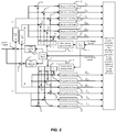
- FIG. 2 is a block diagram showing overall implementation of the data-pilot joint tracking method according to an embodiment of the present invention.
- the local carrier uses two branches, i.e., inphase (I) and quadrature (Q) branches, while the baseband signal uses three branches, i.e., early (E), prompt (P) and late (L) branches.
- the tracking start-point is digital IF signal, with no consideration of AD conversion and down-conversion of RF analog signal.
- P 1 denotes the data-channel power
- d( t ) denotes the data-bit sign at current moment t
- c d denotes the data-channel spreading code
- ⁇ denotes time delay of signal
- ⁇ IF denotes angular frequency of signal
- ⁇ 0 denotes initial phase of carrier
- ⁇ denotes a phase difference between the data baseband signal and the pilot baseband signal
- P 2 denotes the pilot-channel power
- c p denotes the pilot-channel spreading code
- T p denotes coherent integration time
- d denotes the current data bit
- n DIP , n DQP , n PIP , n PQP denote normalized noise after integration of each branch.
- ⁇ is defined as an included angle between the vector 1 ( I DP , Q DP ) and the vector 2 ( I PP , Q PP ) .
- n DIP , n DQP , n PIP , n PQP are white noise with a mean value of 0, so ⁇ should be evenly distributed within 0-180°.
- the maximum-likelihood probability weight is substituted by a weight factor having the same monotone and a relatively high approximation degree.
- Step 7 Implementation of data-pilot joint carrier tuning-amount estimation is shown in a block diagram ( FIG. 4 ).
- the prompt-branch coherent integration results i.e., I PP , Q PP , I DP , Q DP
- I DP and Q DP are respectively multiplied-with the output (i.e., Flip) of the data-bit flip detector-via multipliers 39, 40, to eliminate the influence of data-bit flip.
- phase-discrimination output ⁇ ⁇ is multiplied-with the probability-weighting factor ⁇ 2 -via a multiplier 46, and then through a filtering process in a loop filter 47, an ultimate carrier tuning-amount is obtained.
- the carrier tuning-amount is fed back to the carrier NCO 1, as shown in FIG. 2 , to turn the carrier NCO 1, thereby achieving data-pilot joint signal carrier tracking.
- Step 8 Implementation of data-pilot joint code tuning-amount estimation is shown in a block diagram ( FIG. 5 ).
- the early-branch and late-branch coherent integration results i.e., I PE , Q PE , I PL , Q PL , I DE , Q DE , I DL , Q DL
- I PE , Q DE , I DL , Q DL are utilized for data-pilot joint code tuning-amount estimation.
- I DE , Q DE , I DL , Q DL are respectively multiplied-with the output (i.e., Flip) of the data-bit flip detector-via multipliers 49, 50, 51, 52, to eliminate the influence of data-bit flip.
- the multiplication results are respectively multiplied-with the power-weighting factor ⁇ 1 -via multipliers 53, 54, 55, 56, of which the results are coherently accumulated with I PE , Q PE , I PL , Q PL respectively in adders 57, 58, 59, 60, thereby obtaining the joint coherent integration results I E , Q E, I L , Q L .
- a code phase discriminator In order to maintain the integrity of the invention, a non-coherent early-minus-late discriminator is given herein, while other implementations do not depart from the scope of the present application.
- phase-discrimination result ⁇ ⁇ is multiplied-with the probability-weighting factor-via a multiplier 64, and then through a filtering process in a loop filter 65, an ultimate code tuning-amount is obtained.
- the code tuning-amount is fed back to the code NCO 6, as shown in FIG. 2 , to turn the code NCO 6, thereby achieving baseband signal tracking.
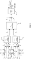
- FIG. 6 is a block diagram showing an overall configuration of a data-pilot joint tracking apparatus according to the present invention
- a carrier NCO 104 controls a local carrier generator 102 to generate a local carrier
- a code NCO 105 controls a baseband signal generator 103 to generates a baseband signal
- the baseband signal generated by the baseband signal generator 103 comprises a data baseband signal and a pilot baseband signal
- the local carrier and a digital IF signal pass through a carrier remover 100 to accomplish carrier removal, then the signal after carrier removal and the baseband signal pass through a code remover 101 to accomplish code removal.
- the signal after code removal passes through an integration-and-dump unit 106 to obtain coherent integration results, of which the prompt-branch coherent integration result is sent into a data-bit flip detector 107 to obtain a data-bit flip detection output Flip; the principle of the data-bit flip detector 107 is as shown in FIG. 3 .
- the prompt-branch coherent integration result is also sent into a probability-weighting factor calculator 108 to obtain a probability-weighting factor ⁇ 2 , of which the principle for implementation is defined by the formula (7).
- the power ratio between the data channel and the pilot channel is utilized by a power-weighting factor calculator 109 to obtain a power-weighting factor ⁇ 1 .
- the prompt-branch coherent integration result is also sent into a data-pilot joint carrier tuning-amount estimator 110, of which a typical embodiment is as shown in FIG. 4 , so that the data-pilot joint carrier tuning-amount estimator 110 obtains a carrier tuning-amount, and by using the carrier tuning-amount to control the carrier NCO 104, data-pilot joint signal carrier tracking is achieved.
- the early-branch and late-branch coherent integration results are sent into a data-pilot joint code tuning-amount estimator 111, of which a typical embodiment is as shown in FIG. 5 , so that the data-pilot joint code tuning-amount estimator 111 obtains a code tuning-amount, and by using the code tuning-amount to control the code NCO 105, baseband signal tracking is achieved.
Landscapes
- Engineering & Computer Science (AREA)
- Radar, Positioning & Navigation (AREA)
- Remote Sensing (AREA)
- Computer Networks & Wireless Communication (AREA)
- Physics & Mathematics (AREA)
- General Physics & Mathematics (AREA)
- Digital Transmission Methods That Use Modulated Carrier Waves (AREA)
- Position Fixing By Use Of Radio Waves (AREA)
Claims (7)
- Navigationssignaldaten-Pilot-Verbindungs-Verfolgungsverfahren, dadurch gekennzeichnet, dass das Verfahren Folgendes umfasst:1) Multiplizieren eines digitalen Zwischenfrequenz(IF)-Signals eines Navigationssignals mit einem Inphase-Zweig eines lokalen Trägers, um ein Inphase-Zweig-Signal /hervorzubringen, und Multiplizieren des digitalen IF-Signals mit einem Quadraturzweig des lokalen Trägers, um ein Quadratur-Zweig-Signal Q hervorzubringen, um eine Trägerbeseitigung zu bewerkstelligen; wobei das digitale IF-Signal ein Datenkanalsignal und ein Pilotkanalsignal umfasst, die die gleiche Frequenz und einen konstanten Phasenunterschied aufweisen; wobei der lokale Träger durch einen numerisch gesteuerten Oszillator (NCO) für den Träger gesteuert wird; wobei der Inphase-Zweig des lokalen Trägers von einem Sinus-Mapping des lokalen Trägers abgeleitet wird, und der Quadratur-Zweig des lokalen Trägers von einem Cosinus-Mapping des lokalen Trägers abgeleitet wird; und das Sinus-Mapping und das Cosinus-Mapping des lokalen Trägers durch den Träger-NCO gesteuert werden;2) Bewerkstelligen einer Code-Beseitigung durch:2a) Multiplizieren einer frühen Instanz, einer zeitnahen Instanz und einer späten Instanz eines Datenbasisbandsignals mit dem Inphase-Zweig-Signal /, um jeweils ein Inphase-Früh-Datensignal, ein Inphase-Zeitnah-Datensignal, und ein Inphase-Spät-Datensignal hervorzubringen; wobei das Datenbasisbandsignal durch einen Code-NCO gesteuert wird;2b) Multiplizieren der frühen Instanz, der zeitnahen Instanz und der späten Instanz des Datenbasisbandsignals mit dem Quadratur-Zweig-Signal Q, um jeweils ein Quadratur-Früh-Datensignal, ein Quadratur-Zeitnah-Datensignal, und ein Quadratur-Spät-Datensignal hervorzubringen;2c) Erhalten eines phasenverschobenen Inphase-Signals I' durch Verschieben einer Phase des Inphase-Zweig-Signals I um eine Phase θ; und Multiplizieren einer frühen Instanz, einer zeitnahen Instanz und einer späten Instanz eines Pilotbasisbandsignals mit dem phasenverschobenen Inphase-Signal I', um jeweils ein Inphase-Früh-Pilotsignal, ein Inphase-Zeitnah-Pilotsignal, und ein Inphase-Spät-Pilotsignal hervorzubringen; wobei das Pilotbasisbandsignal durch den Code-NCO gesteuert wird; und2d) Erhalten eines phasenverschobenen Quadratursignals Q'durch Verschieben einer Phase des Quadratur-Zweig Signals Q um die Phase θ; und Multiplizieren der frühen Instanz, der zeitnahen Instanz und der späten Instanz des Pilotbasisbandsignals mit dem phasenverschobenen Quadratur-Signal Q', um jeweils ein Quadratur-Früh-Pilotsignal; ein Quadratur-Zeitnah-Pilotsignal, und ein Quadratur-Spät-Pilotsignal hervorzubringen;3) Erhalten kohärenter Integrationsergebnisse durch3a) Verarbeiten des Inphase-Früh-Datensignals, des Inphase-Zeitnah-Datensignals, und des Inphase-Spät-Datensignals mit ersten Integrations- und Entladeeinheiten, um jeweils ein kohärentes Daten-Inphase-Früh-Integrationsergebnis IDE, ein kohärentes Daten-Inphase-Zeitnah-Integrationsergebnis IDP, und ein kohärentes Daten-Inphase-Spät-Integrationsergebnis IDL zu erhalten;3b) Verarbeiten des Quadratur-Früh-Datensignals, das Quadratur-Zeitnah-Datensignals, und des Quadratur-Spät-Datensignals mit zweiten Integrations- und Entladeeinheiten, um jeweils ein kohärentes Daten-Quadratur-Früh-Integrationsergebnis QDE, ein kohärentes Daten-Quadratur-Zeitnah-Integrationsergebnis QDP, und ein kohärentes Daten-Quadratur-Spät-Integrationsergebnis QDL zu erhalten;3c) Verarbeiten des Inphase-Früh-Pilotsignals, des Inphase-Zeitnah-Pilotsignals, und des Inphase-Spät-Pilotsignals mit dritten Integrations- und Entladeeinheiten, um jeweils ein kohärentes Pilot-Inphase-Früh-Integrationsergebnis IPE , ein kohärentes Pilot-Inphase-Zeitnah-Integrationsergebnis IPP, und ein kohärentes Pilot-Inphase-Spät-Integrationsergebnis IPL zu erhalten; und3b) Verarbeiten des Quadratur-Früh-Pilotsignals, des Quadratur-Zeitnah-Pilotsignals, und des Quadratur-Spät-Pilotsignals mit vierten Integrations- und Entladeeinheiten, um jeweils ein kohärentes Pilot-Quadratur-Früh-Integrationsergebnis QPE , ein kohärentes Pilot-Quadratur-Zeitnah-Integrationsergebnis QPP, und ein kohärentes Pilot-Quadratur-Spät-Integrationsergebnis QPL zu erhalten;4) Verwenden der kohärenten Integrationsergebnisse des Zeitnah-Zweigs aus den kohärenten Integrationsergebnissen, um eine Datenbit-Flip-Detektion zu bewerkstelligen, um einen Datenbit-Flip-Detektionsausgang Flip=sign(IPP × IDP + QPP × QDP ) zu erhalten, wobei die kohärenten Integrationsergebnisse des Zeitnah-Zweigs IDP, QDP, IPP, und QPP umfassen, sign eine Vorzeichenbitfunktion bezeichnet, und sign (x) einen Ausgang +1 angibt, wenn x gleich oder größer als 0 ist, und einen Ausgang -1 angibt, wenn x geringer als 0 ist;5) Verwenden des Leistungsverhältnisses zwischen dem Datenkanalsignal und dem Pilotkanalsignal, um einen Leistungsgewichtungsfaktor
 6) Verwenden der kohärenten Integrationsergebnisse des Zeitnah-Zweigs, um einen Wahrscheinlichkeitsgewichtungsfaktor α 2 zu berechnen, der die gleiche Monotonie wie die Korrektur-Wahrscheinlichkeit der Datenbit-Flip-Detektion aufweist;7) Berechnen eines kohärenten Inphase-Zeitnah-Integrationsergebnisses IP und eines kohärenten Quadratur-Zeitnah-Integrationsergebnisses QP unter Verwendung der kohärenten Integrationsergebnisse des Zeitnah-Zweigs nach den folgenden Formeln:
 8) Berechnen eines kohärenten Inphase-Früh-Integrationsergebnisses IE , eines kohärenten Inphase-Spät-Integrationsergebnisses IL, eines kohärenten Quadratur-Früh-Integrationsergebnisses QE und eines kohärenten Quadratur-Spät-Integrationsergebnisses QL unter Verwendung der kohärenten Integrationsergebnisse des Früh-Zweigs und der kohärenten Integrationsergebnisse des Spät-Zweigs aus den kohärenten Integrationsergebnisses nach den folgenden Formeln:
 wobei die kohärenten Integrationsergebnisse des Früh-Zweigs IDE, QDE , IPE , und QPE umfassen, und die kohärenten Integrationsergebnisse des Spät-Zweigs IDL, QDL, IPL, und QPL umfassen;Durchführen einer Phasendiskriminierung an dem kohärenten Inphase-Früh-Integrationsergebnis IE , dem kohärenten Inphase-Spät-Integrationsergebnis IL, dem kohärenten Quadratur-Früh-Integrationsergebnis QE und dem kohärenten Quadratur-Spät-Integrationsergebnis QL, um ein Phasendiskriminierungsergebnis Δτ zu erhalten; Multiplizieren des Phasendiskriminierungsergebnisses Δτ mit dem Wahrscheinlichkeitsgewichtungsfaktor α 2 und Durchführen einer Schleifenfilterung, um ein Daten-Pilot-Verbindungs-Codeabstimmausmaß zu erhalten;Rückführen des Daten-Pilot-Verbindungs-Codeabstimmausmaßes zu dem Code-NCO, und Abstimmen des Code-NCOs, um eine Basisbandsignalverfolgung zu bewerkstelligen.
 - Verfahren nach Anspruch 1, dadurch gekennzeichnet, dass das in Schritt 1 erhaltene digitale IF-Signal durch den folgenden Ausdruck gegeben ist:

- Verfahren nach einem der Ansprüche 1 bis 2, dadurch gekennzeichnet, dass in Schritt 4 der Datenbit-Flip-Detektionsausgang Flip = 1 angibt, dass das Datenkanalsignal und das Pilotkanalsignal phasengleich sind, und Flip = -1 angibt, dass zwischen dem Datenkanalsignal und dem Pilotkanalsignal ein Phasenunterschied von 180 ° besteht.
- Verfahren nach einem der Ansprüche 1 bis 2, dadurch gekennzeichnet, dass in Schritt 6 der Wahrscheinlichkeitsgewichtungsfaktor

- Verfahren nach Anspruch 1, dadurch gekennzeichnet, dass in Schritt 7 die Phasendiskriminierung an dem kohärenten Inphase-Zeitnah-Integrationsergebnis IP und dem kohärenten Quadratur-Zeitnah-Integrationsergebnis QP durch Verwenden eines reinen Phasenregelkreis-Phasendiskriminators durchgeführt wird.
- Verfahren nach Anspruch 1, dadurch gekennzeichnet, dass in Schritt 8 die kohärenten Inphase-Früh- und Quadratur-Früh-Integrationsergebnisse IE, QE wie auch die kohärenten Inphase-Spät- und Quadratur-Spät-Integrationsergebnisse IL, QL unter Verwendung der folgenden mathematischen Ausdrücke jeweils mit einer nichtkohärenten Akkumulation durchgeführt werden, um ein frühes nichtkohärentes Akkumulationsergebnis ES und ein spätes nichtkohärentes Akkumulationsergebnis LS zu erhalten:
 N die Anzahl der Male der nichtkohärenten Akkumulation bezeichnet; unddie Phasendiskriminierung an dem frühen nichtkohärenten Akkumulationsergebnis ES und dem späten nichtkohärenten Akkumulationsergebnis LS durchgeführt wird, um das Phasendiskriminierungsergebnis Δτ zu erhalten.
 - Navigationssignaldaten-Pilot-Verbindungs-Verfolgungsvorrichtung, die dazu ausgelegt ist, das Verfahren nach Anspruch 1 durchzuführen.
Applications Claiming Priority (2)
| Application Number | Priority Date | Filing Date | Title |
|---|---|---|---|
| CN201510070094.4A CN104614740B (zh) | 2015-02-10 | 2015-02-10 | 一种导航信号数据导频联合跟踪方法及装置 |
| PCT/CN2015/075671 WO2016127479A1 (zh) | 2015-02-10 | 2015-04-01 | 一种导航信号数据导频联合跟踪方法及装置 |
Publications (3)
| Publication Number | Publication Date |
|---|---|
| EP3258293A1 EP3258293A1 (de) | 2017-12-20 |
| EP3258293A4 EP3258293A4 (de) | 2018-03-07 |
| EP3258293B1 true EP3258293B1 (de) | 2018-11-21 |
Family
ID=53149274
Family Applications (1)
| Application Number | Title | Priority Date | Filing Date |
|---|---|---|---|
| EP15881640.5A Not-in-force EP3258293B1 (de) | 2015-02-10 | 2015-04-01 | Kombiniertes verfolgungsverfahren und vorrichtung für navigationssignal mit datenpilotfrequenz |
Country Status (5)
| Country | Link |
|---|---|
| US (1) | US10649095B2 (de) |
| EP (1) | EP3258293B1 (de) |
| JP (1) | JP6389331B2 (de) |
| CN (1) | CN104614740B (de) |
| WO (1) | WO2016127479A1 (de) |
Families Citing this family (13)
| Publication number | Priority date | Publication date | Assignee | Title |
|---|---|---|---|---|
| CN105204043B (zh) * | 2015-09-15 | 2018-02-13 | 武汉导航与位置服务工业技术研究院有限责任公司 | 信号接收方法及装置 |
| CN106154294B (zh) * | 2016-06-22 | 2019-04-26 | 北京邮电大学 | 一种载波跟踪电路和载波跟踪方法 |
| CN106526635B (zh) * | 2016-12-29 | 2019-02-22 | 中国人民解放军国防科学技术大学 | 一种gnss信号载波跟踪和导航解算紧组合的滤波方法 |
| CN108267756B (zh) * | 2018-01-08 | 2022-06-03 | 中国科学院光电研究院 | 一种基于加权最小二乘的复合载波导航信号联合跟踪方法 |
| US10746882B2 (en) | 2018-02-21 | 2020-08-18 | Samsung Electronics Co., Ltd | GNSS receiver performance improvement via long coherent integration |
| CN110196435A (zh) * | 2018-02-27 | 2019-09-03 | 中国科学院微电子研究所 | 信号的处理方法、装置、存储介质和处理器 |
| CN109581438B (zh) * | 2018-11-08 | 2022-06-10 | 上海司南卫星导航技术股份有限公司 | 一种估计载噪比的方法、载噪比估计装置、终端以及计算机可读介质 |
| CN112118200B (zh) * | 2020-09-07 | 2023-03-31 | 北京航宇星通科技有限公司 | 跟踪方法及系统 |
| CN113238261B (zh) * | 2021-05-31 | 2022-12-13 | 西南电子技术研究所(中国电子科技集团公司第十研究所) | 低轨卫星扩频通信体制信号捕获跟踪系统 |
| CN113534207A (zh) * | 2021-09-02 | 2021-10-22 | 重庆两江卫星移动通信有限公司 | 一种时分体制的导航增强信号跟踪方法及系统 |
| CN114296110B (zh) * | 2021-12-29 | 2024-10-29 | 航天恒星科技有限公司 | 多频点联合载波频率跟踪方法及装置 |
| CN115657093B (zh) * | 2022-12-29 | 2023-03-31 | 成都奇芯微电子有限公司 | 基于捕获数据存储的方法 |
| US20250244486A1 (en) * | 2024-01-30 | 2025-07-31 | Avago Technologies International Sales Pte. Limited | Tracking performance improvement by combining components of a global navigation satellite system signal |
Family Cites Families (8)
| Publication number | Priority date | Publication date | Assignee | Title |
|---|---|---|---|---|
| US7706431B2 (en) * | 2005-06-30 | 2010-04-27 | Nokia Corporation | System and method for providing optimized receiver architectures for combined pilot and data signal tracking |
| JP5005446B2 (ja) * | 2007-07-03 | 2012-08-22 | 日本無線株式会社 | 自立型高感度衛星信号受信機 |
| CN101183149B (zh) * | 2007-12-07 | 2010-09-01 | 清华大学 | 双更新率载波跟踪环路 |
| US8594244B2 (en) * | 2009-04-06 | 2013-11-26 | Mediatek Inc. | Data signal phase reversal correction method and system implementing the same |
| US8520719B2 (en) * | 2009-05-29 | 2013-08-27 | Qualcomm Incorporated | Multiple-mode correlator |
| US8401546B2 (en) * | 2010-04-26 | 2013-03-19 | Ecole De Technologie Superieure | Universal acquisition and tracking apparatus for global navigation satellite system (GNSS) |
| EP2811320A1 (de) * | 2013-06-05 | 2014-12-10 | Astrium Limited | Empfänger und Verfahren für Direktsequenz-Spreizspektrum-Signale |
| CN103558612B (zh) * | 2013-11-21 | 2015-12-30 | 天津七一二通信广播有限公司 | 锁相环与副载波环联合鉴相跟踪环路 |
-
2015
- 2015-02-10 CN CN201510070094.4A patent/CN104614740B/zh not_active Expired - Fee Related
- 2015-04-01 WO PCT/CN2015/075671 patent/WO2016127479A1/zh not_active Ceased
- 2015-04-01 JP JP2017520470A patent/JP6389331B2/ja not_active Expired - Fee Related
- 2015-04-01 EP EP15881640.5A patent/EP3258293B1/de not_active Not-in-force
-
2017
- 2017-05-03 US US15/586,254 patent/US10649095B2/en not_active Expired - Fee Related
Non-Patent Citations (1)
| Title |
|---|
| None * |
Also Published As
| Publication number | Publication date |
|---|---|
| EP3258293A1 (de) | 2017-12-20 |
| JP6389331B2 (ja) | 2018-09-12 |
| EP3258293A4 (de) | 2018-03-07 |
| US10649095B2 (en) | 2020-05-12 |
| US20170234987A1 (en) | 2017-08-17 |
| CN104614740A (zh) | 2015-05-13 |
| CN104614740B (zh) | 2016-08-17 |
| JP2017531193A (ja) | 2017-10-19 |
| WO2016127479A1 (zh) | 2016-08-18 |
Similar Documents
| Publication | Publication Date | Title |
|---|---|---|
| EP3258293A1 (de) | Kombiniertes verfolgungsverfahren und vorrichtung für navigationssignal mit datenpilotfrequenz | |
| CN101839987B (zh) | 一种自适应gps软件接收机的实现方法 | |
| CN105917585B (zh) | 用于接收复合信号的方法和接收器 | |
| US20070205940A1 (en) | Method and device for tracking weak global navigation satellite system (gnss) signals | |
| US9705667B2 (en) | Tracking of signals with at least one subcarrier | |
| CN101523234A (zh) | 二进制偏移载波调制信号的接收机 | |
| CN104536016B (zh) | 一种gnss新体制信号捕获装置及方法 | |
| CN101826889A (zh) | 一种二进制偏移载波信号跟踪环路 | |
| CN105527635A (zh) | 一种捕获微弱信号的方法和装置 | |
| CN103558612B (zh) | 锁相环与副载波环联合鉴相跟踪环路 | |
| JP4755920B2 (ja) | キャリア位相追尾装置および擬似雑音コード信号追尾装置 | |
| WO2021226986A1 (zh) | 一种定位方法、定位芯片和终端设备 | |
| CN102590835A (zh) | 一种gps/ins深组合跟踪环路高斯码相位鉴别器及其设计方法 | |
| CN104931980A (zh) | 载波相位测量半周模糊解除方法 | |
| US20240295663A1 (en) | Snapshot gnss receiver and method using super-long coherent integration and fractional fourier transform | |
| JP4869022B2 (ja) | 衛星信号追尾装置及びそれを備えた衛星信号受信機 | |
| WO2006030575A1 (ja) | L2c信号追尾装置およびこれを用いたgps受信機 | |
| US20140348275A1 (en) | Systems and methods for estimating pseudorange errors | |
| CN104977594B (zh) | 基于非合作导航卫星信号的无码多普勒定轨方法 | |
| CN117590446B (zh) | 宽带复合导航信号跟踪方法及装置 | |
| US12618978B2 (en) | Demodulating QZSS signals | |
| JP3837419B2 (ja) | 衛星測位方法及び衛星測位システム | |
| JP2008252162A (ja) | 拡散信号受信装置 | |
| CN118604855B (zh) | B1c导航信号的匹配跟踪方法及装置 | |
| CN117687053B (zh) | 宽带复合导航信号跟踪方法及装置 |
Legal Events
| Date | Code | Title | Description |
|---|---|---|---|
| STAA | Information on the status of an ep patent application or granted ep patent |
Free format text: STATUS: THE INTERNATIONAL PUBLICATION HAS BEEN MADE |
|
| PUAI | Public reference made under article 153(3) epc to a published international application that has entered the european phase |
Free format text: ORIGINAL CODE: 0009012 |
|
| STAA | Information on the status of an ep patent application or granted ep patent |
Free format text: STATUS: REQUEST FOR EXAMINATION WAS MADE |
|
| 17P | Request for examination filed |
Effective date: 20170505 |
|
| AK | Designated contracting states |
Kind code of ref document: A1 Designated state(s): AL AT BE BG CH CY CZ DE DK EE ES FI FR GB GR HR HU IE IS IT LI LT LU LV MC MK MT NL NO PL PT RO RS SE SI SK SM TR |
|
| AX | Request for extension of the european patent |
Extension state: BA ME |
|
| REG | Reference to a national code |
Ref country code: DE Ref legal event code: R079 Ref document number: 602015020227 Country of ref document: DE Free format text: PREVIOUS MAIN CLASS: G01S0019240000 Ipc: G01S0019290000 |
|
| A4 | Supplementary search report drawn up and despatched |
Effective date: 20180206 |
|
| RIC1 | Information provided on ipc code assigned before grant |
Ipc: G01S 19/30 20100101ALI20180131BHEP Ipc: G01S 19/24 20100101ALI20180131BHEP Ipc: G01S 19/29 20100101AFI20180131BHEP |
|
| STAA | Information on the status of an ep patent application or granted ep patent |
Free format text: STATUS: EXAMINATION IS IN PROGRESS |
|
| 17Q | First examination report despatched |
Effective date: 20180417 |
|
| DAV | Request for validation of the european patent (deleted) | ||
| DAX | Request for extension of the european patent (deleted) | ||
| GRAP | Despatch of communication of intention to grant a patent |
Free format text: ORIGINAL CODE: EPIDOSNIGR1 |
|
| STAA | Information on the status of an ep patent application or granted ep patent |
Free format text: STATUS: GRANT OF PATENT IS INTENDED |
|
| INTG | Intention to grant announced |
Effective date: 20180723 |
|
| RIN1 | Information on inventor provided before grant (corrected) |
Inventor name: SHI, JIANFENG Inventor name: TANG, ZUPING Inventor name: WEI, JIAOLONG |
|
| GRAS | Grant fee paid |
Free format text: ORIGINAL CODE: EPIDOSNIGR3 |
|
| GRAA | (expected) grant |
Free format text: ORIGINAL CODE: 0009210 |
|
| STAA | Information on the status of an ep patent application or granted ep patent |
Free format text: STATUS: THE PATENT HAS BEEN GRANTED |
|
| AK | Designated contracting states |
Kind code of ref document: B1 Designated state(s): AL AT BE BG CH CY CZ DE DK EE ES FI FR GB GR HR HU IE IS IT LI LT LU LV MC MK MT NL NO PL PT RO RS SE SI SK SM TR |
|
| REG | Reference to a national code |
Ref country code: CH Ref legal event code: EP |
|
| REG | Reference to a national code |
Ref country code: IE Ref legal event code: FG4D |
|
| REG | Reference to a national code |
Ref country code: DE Ref legal event code: R096 Ref document number: 602015020227 Country of ref document: DE |
|
| REG | Reference to a national code |
Ref country code: AT Ref legal event code: REF Ref document number: 1068201 Country of ref document: AT Kind code of ref document: T Effective date: 20181215 |
|
| REG | Reference to a national code |
Ref country code: CH Ref legal event code: NV Representative=s name: LANGPATENT ANWALTSKANZLEI IP LAW FIRM, CH |
|
| REG | Reference to a national code |
Ref country code: NL Ref legal event code: MP Effective date: 20181121 |
|
| REG | Reference to a national code |
Ref country code: AT Ref legal event code: MK05 Ref document number: 1068201 Country of ref document: AT Kind code of ref document: T Effective date: 20181121 |
|
| PG25 | Lapsed in a contracting state [announced via postgrant information from national office to epo] |
Ref country code: FI Free format text: LAPSE BECAUSE OF FAILURE TO SUBMIT A TRANSLATION OF THE DESCRIPTION OR TO PAY THE FEE WITHIN THE PRESCRIBED TIME-LIMIT Effective date: 20181121 Ref country code: LV Free format text: LAPSE BECAUSE OF FAILURE TO SUBMIT A TRANSLATION OF THE DESCRIPTION OR TO PAY THE FEE WITHIN THE PRESCRIBED TIME-LIMIT Effective date: 20181121 Ref country code: HR Free format text: LAPSE BECAUSE OF FAILURE TO SUBMIT A TRANSLATION OF THE DESCRIPTION OR TO PAY THE FEE WITHIN THE PRESCRIBED TIME-LIMIT Effective date: 20181121 Ref country code: LT Free format text: LAPSE BECAUSE OF FAILURE TO SUBMIT A TRANSLATION OF THE DESCRIPTION OR TO PAY THE FEE WITHIN THE PRESCRIBED TIME-LIMIT Effective date: 20181121 Ref country code: BG Free format text: LAPSE BECAUSE OF FAILURE TO SUBMIT A TRANSLATION OF THE DESCRIPTION OR TO PAY THE FEE WITHIN THE PRESCRIBED TIME-LIMIT Effective date: 20190221 Ref country code: AT Free format text: LAPSE BECAUSE OF FAILURE TO SUBMIT A TRANSLATION OF THE DESCRIPTION OR TO PAY THE FEE WITHIN THE PRESCRIBED TIME-LIMIT Effective date: 20181121 Ref country code: ES Free format text: LAPSE BECAUSE OF FAILURE TO SUBMIT A TRANSLATION OF THE DESCRIPTION OR TO PAY THE FEE WITHIN THE PRESCRIBED TIME-LIMIT Effective date: 20181121 Ref country code: NO Free format text: LAPSE BECAUSE OF FAILURE TO SUBMIT A TRANSLATION OF THE DESCRIPTION OR TO PAY THE FEE WITHIN THE PRESCRIBED TIME-LIMIT Effective date: 20190221 Ref country code: IS Free format text: LAPSE BECAUSE OF FAILURE TO SUBMIT A TRANSLATION OF THE DESCRIPTION OR TO PAY THE FEE WITHIN THE PRESCRIBED TIME-LIMIT Effective date: 20190321 |
|
| PG25 | Lapsed in a contracting state [announced via postgrant information from national office to epo] |
Ref country code: GR Free format text: LAPSE BECAUSE OF FAILURE TO SUBMIT A TRANSLATION OF THE DESCRIPTION OR TO PAY THE FEE WITHIN THE PRESCRIBED TIME-LIMIT Effective date: 20190222 Ref country code: PT Free format text: LAPSE BECAUSE OF FAILURE TO SUBMIT A TRANSLATION OF THE DESCRIPTION OR TO PAY THE FEE WITHIN THE PRESCRIBED TIME-LIMIT Effective date: 20190321 Ref country code: NL Free format text: LAPSE BECAUSE OF FAILURE TO SUBMIT A TRANSLATION OF THE DESCRIPTION OR TO PAY THE FEE WITHIN THE PRESCRIBED TIME-LIMIT Effective date: 20181121 Ref country code: RS Free format text: LAPSE BECAUSE OF FAILURE TO SUBMIT A TRANSLATION OF THE DESCRIPTION OR TO PAY THE FEE WITHIN THE PRESCRIBED TIME-LIMIT Effective date: 20181121 Ref country code: SE Free format text: LAPSE BECAUSE OF FAILURE TO SUBMIT A TRANSLATION OF THE DESCRIPTION OR TO PAY THE FEE WITHIN THE PRESCRIBED TIME-LIMIT Effective date: 20181121 Ref country code: AL Free format text: LAPSE BECAUSE OF FAILURE TO SUBMIT A TRANSLATION OF THE DESCRIPTION OR TO PAY THE FEE WITHIN THE PRESCRIBED TIME-LIMIT Effective date: 20181121 |
|
| PG25 | Lapsed in a contracting state [announced via postgrant information from national office to epo] |
Ref country code: IT Free format text: LAPSE BECAUSE OF FAILURE TO SUBMIT A TRANSLATION OF THE DESCRIPTION OR TO PAY THE FEE WITHIN THE PRESCRIBED TIME-LIMIT Effective date: 20181121 Ref country code: CZ Free format text: LAPSE BECAUSE OF FAILURE TO SUBMIT A TRANSLATION OF THE DESCRIPTION OR TO PAY THE FEE WITHIN THE PRESCRIBED TIME-LIMIT Effective date: 20181121 Ref country code: DK Free format text: LAPSE BECAUSE OF FAILURE TO SUBMIT A TRANSLATION OF THE DESCRIPTION OR TO PAY THE FEE WITHIN THE PRESCRIBED TIME-LIMIT Effective date: 20181121 Ref country code: PL Free format text: LAPSE BECAUSE OF FAILURE TO SUBMIT A TRANSLATION OF THE DESCRIPTION OR TO PAY THE FEE WITHIN THE PRESCRIBED TIME-LIMIT Effective date: 20181121 |
|
| REG | Reference to a national code |
Ref country code: DE Ref legal event code: R097 Ref document number: 602015020227 Country of ref document: DE |
|
| PG25 | Lapsed in a contracting state [announced via postgrant information from national office to epo] |
Ref country code: SM Free format text: LAPSE BECAUSE OF FAILURE TO SUBMIT A TRANSLATION OF THE DESCRIPTION OR TO PAY THE FEE WITHIN THE PRESCRIBED TIME-LIMIT Effective date: 20181121 Ref country code: EE Free format text: LAPSE BECAUSE OF FAILURE TO SUBMIT A TRANSLATION OF THE DESCRIPTION OR TO PAY THE FEE WITHIN THE PRESCRIBED TIME-LIMIT Effective date: 20181121 Ref country code: SK Free format text: LAPSE BECAUSE OF FAILURE TO SUBMIT A TRANSLATION OF THE DESCRIPTION OR TO PAY THE FEE WITHIN THE PRESCRIBED TIME-LIMIT Effective date: 20181121 Ref country code: RO Free format text: LAPSE BECAUSE OF FAILURE TO SUBMIT A TRANSLATION OF THE DESCRIPTION OR TO PAY THE FEE WITHIN THE PRESCRIBED TIME-LIMIT Effective date: 20181121 |
|
| PLBE | No opposition filed within time limit |
Free format text: ORIGINAL CODE: 0009261 |
|
| STAA | Information on the status of an ep patent application or granted ep patent |
Free format text: STATUS: NO OPPOSITION FILED WITHIN TIME LIMIT |
|
| 26N | No opposition filed |
Effective date: 20190822 |
|
| PG25 | Lapsed in a contracting state [announced via postgrant information from national office to epo] |
Ref country code: SI Free format text: LAPSE BECAUSE OF FAILURE TO SUBMIT A TRANSLATION OF THE DESCRIPTION OR TO PAY THE FEE WITHIN THE PRESCRIBED TIME-LIMIT Effective date: 20181121 |
|
| REG | Reference to a national code |
Ref country code: BE Ref legal event code: MM Effective date: 20190430 |
|
| PG25 | Lapsed in a contracting state [announced via postgrant information from national office to epo] |
Ref country code: MC Free format text: LAPSE BECAUSE OF FAILURE TO SUBMIT A TRANSLATION OF THE DESCRIPTION OR TO PAY THE FEE WITHIN THE PRESCRIBED TIME-LIMIT Effective date: 20181121 Ref country code: LU Free format text: LAPSE BECAUSE OF NON-PAYMENT OF DUE FEES Effective date: 20190401 |
|
| PG25 | Lapsed in a contracting state [announced via postgrant information from national office to epo] |
Ref country code: BE Free format text: LAPSE BECAUSE OF NON-PAYMENT OF DUE FEES Effective date: 20190430 |
|
| PG25 | Lapsed in a contracting state [announced via postgrant information from national office to epo] |
Ref country code: TR Free format text: LAPSE BECAUSE OF FAILURE TO SUBMIT A TRANSLATION OF THE DESCRIPTION OR TO PAY THE FEE WITHIN THE PRESCRIBED TIME-LIMIT Effective date: 20181121 |
|
| PG25 | Lapsed in a contracting state [announced via postgrant information from national office to epo] |
Ref country code: IE Free format text: LAPSE BECAUSE OF NON-PAYMENT OF DUE FEES Effective date: 20190401 |
|
| PGFP | Annual fee paid to national office [announced via postgrant information from national office to epo] |
Ref country code: DE Payment date: 20200625 Year of fee payment: 6 Ref country code: FR Payment date: 20200605 Year of fee payment: 6 |
|
| PGFP | Annual fee paid to national office [announced via postgrant information from national office to epo] |
Ref country code: GB Payment date: 20200529 Year of fee payment: 6 |
|
| PGFP | Annual fee paid to national office [announced via postgrant information from national office to epo] |
Ref country code: CH Payment date: 20200825 Year of fee payment: 6 |
|
| PG25 | Lapsed in a contracting state [announced via postgrant information from national office to epo] |
Ref country code: CY Free format text: LAPSE BECAUSE OF FAILURE TO SUBMIT A TRANSLATION OF THE DESCRIPTION OR TO PAY THE FEE WITHIN THE PRESCRIBED TIME-LIMIT Effective date: 20181121 |
|
| PG25 | Lapsed in a contracting state [announced via postgrant information from national office to epo] |
Ref country code: HU Free format text: LAPSE BECAUSE OF FAILURE TO SUBMIT A TRANSLATION OF THE DESCRIPTION OR TO PAY THE FEE WITHIN THE PRESCRIBED TIME-LIMIT; INVALID AB INITIO Effective date: 20150401 Ref country code: MT Free format text: LAPSE BECAUSE OF FAILURE TO SUBMIT A TRANSLATION OF THE DESCRIPTION OR TO PAY THE FEE WITHIN THE PRESCRIBED TIME-LIMIT Effective date: 20181121 |
|
| REG | Reference to a national code |
Ref country code: DE Ref legal event code: R119 Ref document number: 602015020227 Country of ref document: DE |
|
| GBPC | Gb: european patent ceased through non-payment of renewal fee |
Effective date: 20210401 |
|
| PG25 | Lapsed in a contracting state [announced via postgrant information from national office to epo] |
Ref country code: DE Free format text: LAPSE BECAUSE OF NON-PAYMENT OF DUE FEES Effective date: 20211103 Ref country code: GB Free format text: LAPSE BECAUSE OF NON-PAYMENT OF DUE FEES Effective date: 20210401 Ref country code: FR Free format text: LAPSE BECAUSE OF NON-PAYMENT OF DUE FEES Effective date: 20210430 Ref country code: CH Free format text: LAPSE BECAUSE OF NON-PAYMENT OF DUE FEES Effective date: 20210430 Ref country code: LI Free format text: LAPSE BECAUSE OF NON-PAYMENT OF DUE FEES Effective date: 20210430 |
|
| PG25 | Lapsed in a contracting state [announced via postgrant information from national office to epo] |
Ref country code: MK Free format text: LAPSE BECAUSE OF FAILURE TO SUBMIT A TRANSLATION OF THE DESCRIPTION OR TO PAY THE FEE WITHIN THE PRESCRIBED TIME-LIMIT Effective date: 20181121 |