EP2811320A1 - Empfänger und Verfahren für Direktsequenz-Spreizspektrum-Signale - Google Patents
Empfänger und Verfahren für Direktsequenz-Spreizspektrum-Signale Download PDFInfo
- Publication number
- EP2811320A1 EP2811320A1 EP13275134.8A EP13275134A EP2811320A1 EP 2811320 A1 EP2811320 A1 EP 2811320A1 EP 13275134 A EP13275134 A EP 13275134A EP 2811320 A1 EP2811320 A1 EP 2811320A1
- Authority
- EP
- European Patent Office
- Prior art keywords
- correlation
- phase
- dsss
- signal
- correlation functions
- Prior art date
- Legal status (The legal status is an assumption and is not a legal conclusion. Google has not performed a legal analysis and makes no representation as to the accuracy of the status listed.)
- Ceased
Links
Images


Classifications
-
- G—PHYSICS
- G01—MEASURING; TESTING
- G01S—RADIO DIRECTION-FINDING; RADIO NAVIGATION; DETERMINING DISTANCE OR VELOCITY BY USE OF RADIO WAVES; LOCATING OR PRESENCE-DETECTING BY USE OF THE REFLECTION OR RERADIATION OF RADIO WAVES; ANALOGOUS ARRANGEMENTS USING OTHER WAVES
- G01S19/00—Satellite radio beacon positioning systems; Determining position, velocity or attitude using signals transmitted by such systems
- G01S19/01—Satellite radio beacon positioning systems transmitting time-stamped messages, e.g. GPS [Global Positioning System], GLONASS [Global Orbiting Navigation Satellite System] or GALILEO
- G01S19/13—Receivers
- G01S19/24—Acquisition or tracking or demodulation of signals transmitted by the system
- G01S19/29—Acquisition or tracking or demodulation of signals transmitted by the system carrier including Doppler, related
-
- G—PHYSICS
- G01—MEASURING; TESTING
- G01S—RADIO DIRECTION-FINDING; RADIO NAVIGATION; DETERMINING DISTANCE OR VELOCITY BY USE OF RADIO WAVES; LOCATING OR PRESENCE-DETECTING BY USE OF THE REFLECTION OR RERADIATION OF RADIO WAVES; ANALOGOUS ARRANGEMENTS USING OTHER WAVES
- G01S19/00—Satellite radio beacon positioning systems; Determining position, velocity or attitude using signals transmitted by such systems
- G01S19/01—Satellite radio beacon positioning systems transmitting time-stamped messages, e.g. GPS [Global Positioning System], GLONASS [Global Orbiting Navigation Satellite System] or GALILEO
- G01S19/13—Receivers
- G01S19/24—Acquisition or tracking or demodulation of signals transmitted by the system
- G01S19/30—Acquisition or tracking or demodulation of signals transmitted by the system code related
Definitions
- the present invention relates to an apparatus and method for receiving and processing a Direct Sequence Spread Spectrum (DSSS) signal. More particularly, the present invention relates to processing a DSSS signal by obtaining a correlation function, for use in DSSS code and carrier tracking, using a time and frequency transform based correlation method.
- DSSS Direct Sequence Spread Spectrum
- Direct Sequence Spread Spectrum (DSSS) modulation is used in a wide variety of applications, including Global Navigation Satellite Systems (GNSS), radio frequency ranging systems, radio frequency time transfer systems, anti-jamming receivers and channel sounding.
- GNSS Global Navigation Satellite Systems
- a DSSS signal comprises a carrier wave that has been phase-modulated with a sequence of pseudonoise "chips", each chip having a much shorter duration than an information bit.
- the sequence of chips can be referred to as a spreading code.
- the information signal can be recovered from a received DSSS signal by multiplying the received DSSS signal with a replica of the spreading code. This demodulation process requires the replica spreading code to be accurately aligned in frequency and phase with the received DSSS signal.
- the first stage is acquisition, this involves establishing an initial estimation of the received spread signal frequency and the code phase.
- the initial estimates allow the replica spreading code to be aligned to within ⁇ 1 code chip.
- the replica spreading code phase is more accurately synchronised to the received code phase to de-spread the received DSSS signal, and a Frequency Lock Loop (FLL) and Phase Lock Loop (PLL) accurately track the frequency and phase of the de-spread signal.
- FLL Frequency Lock Loop
- PLL Phase Lock Loop
- a conventional code tracking implementation is shown in Fig. 1 , and includes a Delay Lock Loop (DLL) which performs correlations of the input signals with early (by a fraction of a chip), prompt (on time) and late (by a fraction of a chip) versions of the replica spreading code.
- the code tracking apparatus receives an intermediate frequency (IF) signal, which is a down-converted received DSSS signal.
- IF intermediate frequency
- the IF signal is mixed with sine and cosine waveforms generated by a carrier Numerically Controlled Oscillator (NCO) 101 to generate In-phase (I) and Quadrature (Q) components.
- the I and Q components are each correlated with the Early (E), Prompt (P), and Late (L) versions of the replica spreading code, generated by a code generator 102, and passed through Integrate and Dump (I&D) filters.
- a DLL discriminator 103 outputs an error signal corresponding to the difference between the early and late correlator outputs, which gives an indicator of the loop error.
- the error signal is passed through a code filter 104 and used to drive the code generator 102 appropriately to synchronise the received signal with the replica code sequence.
- the loop discriminator is based on an ATAN function 105 and uses the prompt correlator as its input.
- the output of the ATAN function 105 is filtered in a carrier loop filter 106 and fed back to control the carrier NCO 101.
- a drawback of this design is that the code and carrier loops are tightly coupled, since the output of the DLL discriminator 103 in the code loop will be affected by changes in the carrier NCO frequency and phase caused by operation of the carrier loop.
- DLL operation is generally based on discriminators which operate on signal envelopes or powers, with the result that the loop action is a non-coherent averaging process.
- a conventional DLL tracking loop as shown in Fig. 1 can also suffer from false lock due to tracking on a correlation side lobe, as well as impaired tracking accuracy in the presence of multipath interference.
- a method of processing a Direct Sequence Spread Spectrum DSSS signal comprising: performing DSSS acquisition to obtain estimates of a frequency offset and a spreading code phase; sequentially obtaining, for each one of a plurality of segments of a received DSSS signal, a correlation function between the DSSS signal segment and a replica of a spreading code by using a time and frequency transform based correlation method with coarse Doppler compensation, the estimated frequency offset and the spreading code phase; and performing DSSS carrier tracking by tracking the phase of a correlation peak in the obtained correlation functions, and applying phase corrections to the obtained correlation functions to provide fine Doppler compensation.
- Performing DSSS carrier tracking can comprise obtaining code and carrier phase estimates, and the method can further comprise: obtaining an estimate of the spreading code phase over time based on the code and carrier phase estimates, using a curve fitting process. Estimating the spreading code phase over time using curve fitting can give enhanced performance in low signal to noise scenarios.
- the curve fitting can, for example, be applied using linear regression or a Kalman filter.
- the receiver can be a GNSS receiver, and the method can further comprise: obtaining a plurality of pseudoranges using the obtained estimate of the spreading code phase over time; and processing the obtained pseudoranges in a navigation algorithm to obtain an estimated location.
- the method can further comprise: receiving a plurality of DSSS signals from spatially separate signal paths; obtaining, for each of the received DSSS signals, the plurality of correlation functions; time-aligning the obtained correlation functions from different ones of the received DSSS signals; and summing the time-aligned correlation functions.
- the method can further comprise: detecting a phase offset between the correlation peaks in two of the plurality of correlation functions; applying a phase rotation to one of the two correlation functions, to align the correlation peaks in the two correlation functions; and summing the peak-aligned correlation functions.
- the method can further comprise: interpolating between phases of the correlation peaks in successive ones of the correlation functions, to obtain a fractional offset value; aligning the correlation peaks in the plurality of correlation functions based on the obtained fractional offset; and summing the peak-aligned correlation functions.
- the time and frequency transform based correlation method can involve, for each segment of the received DSSS signal, obtaining a plurality of samples and transforming the samples from the time domain to the frequency domain, wherein the DSSS receiver is a Global Navigation Satellite System GNSS receiver comprising a plurality of receiving channels each arranged to track a DSSS signal received from a different one of a plurality of GNSS satellites, and wherein the method can further comprise: sharing each of the transformed signal samples with each one of the plurality of receiving channels.
- GNSS Global Navigation Satellite System
- Obtaining each one of the plurality of correlation functions can comprise: obtaining data samples of the segment of the received DSSS signal; and zero padding the obtained data samples to increase a frequency resolution of the transformed domain based correlation method.
- the time and frequency transform based correlation method can use a Fast Fourier Transform FFT, a non-uniform discrete Fourier transform, discrete sine and cosine transforms, or a fractional Fourier transform.
- FFT Fast Fourier Transform
- non-uniform discrete Fourier transform discrete sine and cosine transforms
- fractional Fourier transform discrete sine and cosine transforms
- Performing DSSS acquisition can comprise: obtaining a plurality of acquisition correlation functions; estimating a Doppler offset from changes in phase of the correlation peak within the obtained acquisition correlation functions; coherently summing the acquisition correlation functions based on the estimated Doppler offset; and determining that acquisition is successful if a correlation peak in the summed acquisition correlation function exceeds a predetermined threshold.
- the received DSSS signal can be a phase shift keying PSK modulated signal
- the method can further comprise: obtaining a correlation function for each one of a plurality of data symbols in the received DSSS signal; estimating, for each one of the obtained correlation functions, a data polarity; removing the estimated data polarity from each of the obtained correlation functions; and summing the correlation functions for the plurality of data symbols, after removing the estimated data polarities.
- the plurality of segments each can have a length less than a duration of one data symbol
- obtaining the correlation function for each one of a plurality of data symbols in the received DSSS signal can comprise: obtaining correlation functions for each one of a predetermined number of the segments; aligning the obtained correlation functions in phase, based on a Doppler estimate obtained during the DSSS acquisition; and summing the predetermined number of aligned correlation functions to obtain an integrated correlation function for said one of the plurality of data symbols.
- a computer-readable storage medium arranged to store a computer program, which when executed, performs the method.
- apparatus for receiving a Direct Sequence Spread Spectrum DSSS signal comprising: means for performing DSSS acquisition to obtain estimates of a frequency offset and a spreading code phase; means for sequentially obtaining, for each one of a plurality of segments of a received DSSS signal, a correlation function between the DSSS signal segment and a replica of a spreading code by using a time and frequency transform based correlation method with coarse Doppler compensation, the estimated frequency and the spreading code phase; and means for performing DSSS carrier tracking by tracking the phase of a correlation peak in the obtained correlation functions, and applying phase corrections to the obtained correlation functions to provide fine Doppler compensation.
- the means for performing DSSS carrier tracking can be arranged to detect a change in the phase and a code index of the correlation peak over time in the obtained correlation functions.
- the DSSS signal can comprise a data signal modulated by a spreading code
- performing DSSS carrier tracking can comprise inputting the phase of the correlation peak into a phase tracking loop arranged to correct a phase of the correlation function
- the method can further comprise recovering the data signal using in-phase and quadrature components of the correlation peak.
- the correlation function may comprise a plurality of correlation samples distributed across a plurality of correlation bins.
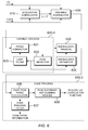
- Figures 2 and 3 illustrate an apparatus for demodulating a DSSS signal, according to an embodiment of the present invention.
- the present embodiment uses a generalised time and frequency domain transform approach to perform coherent tracking of DSSS carriers, by using an estimated coherent complex correlation function as a source of phase information.
- the apparatus comprises a DSSS acquisition correlator 210, a DSSS tracking correlator 220, and a DSSS tracking algorithm 230.
- a DSSS acquisition correlator 210 receives a DSSS signal from the apparatus and uses a DSSS signal to generate a DSSS signal.
- a DSSS tracking correlator 220 receives a DSSS signal from the apparatus.
- a single correlator may perform correlation for both acquisition and tracking processes.
- any means for obtaining an acquisition correlation function and a tracking correlation function may be provided.
- the acquisition correlator 210 and the tracking correlator 220 both receive I and Q samples of a received DSSS signal.
- a DSSS receiver including the apparatus of Fig. 2 can further comprise an antenna arranged to receive a DSSS signal, an amplifier arranged to amplify the received DSSS signal, a down-converting module arranged to down-convert the amplified DSSS signal to an IF signal, and an analogue-to-digital converter (ADC) arranged to sample the IF signal and output digitised samples of the DSSS signal.
- ADC analogue-to-digital converter
- the I and Q samples can be obtained from the ADC output samples by multiplying with local oscillator sine and cosine waveforms.
- the acquisition correlator 210 and the tracking correlator 220 both receive samples of a replica spreading code.
- the samples of the replica spreading code can be stored in memory and retrieved when required for correlation, or can be generated on-demand by a pseudo-random number (PRN) code generator arranged to output the required PRN code for the signal source to be tracked, for instance a GNSS satellite.
- PRN pseudo-random number
- the acquisition correlator 210 performs DSSS acquisition to obtain initial estimates of a frequency offset and a spreading code phase, by correlating the input I and Q samples to the code samples. Then, once acquisition has been performed, the tracking correlator 220 sequentially obtains, for each one of a plurality of segments of the received DSSS signal, a correlation function between the DSSS signal segment and the corresponding segment of the replica spreading code.
- the correlation functions are input to the DSSS tracking algorithm, which performs DSSS carrier tracking by comparing the position and phase of a correlation peak in one of the obtained correlation functions to a previous position and phase of the correlation peak. In this way, the DSSS tracking algorithm can monitor changes in the peak phase over time, in order to perform carrier and/or code phase tracking.
- the tracking correlator 220 of the present embodiment exploits the fact that a correlation process is very similar to a convolution process, and that a convolution in the time domain is equivalent to a multiplication in the frequency domain.
- the estimated frequency and spreading code phase obtained during DSSS acquisition by the acquisition correlator 210 are input to the tracking correlator 220, which uses a Time and Frequency Transform based correlation method to obtain the correlation function.
- the Time and Frequency Transform based correlation method is similar to that used in a conventional GNSS receiver for DSSS acquisition, but in the present embodiment the correlation is performed during DSSS tracking and the correlation function is input to the tracking algorithm 230.
- the tracking algorithm 230 performs DSSS carrier tracking by tracking the phase over time of a correlation peak in the correlation functions received from the tracking correlator 220, and applying phase corrections to the obtained correlation functions to provide fine Doppler compensation. In this way, fine Doppler compensation is achieved by applying post-corrections after correlation has been performed.
- the approach used in the present embodiment means that the carrier loop and the primary correlation function are decoupled. This provides a more robust process that is less sensitive to carrier tracking estimates, allowing the receiver to track in very low signal to noise environments.
- the tracking correlator 220 is shown in more detail in Fig. 3 , and comprises a first forward Fast Fourier Transform (FFT) function 221, a second FFT function 222, and a complex conjugate function 223 arranged to provide the complex conjugate of the output of the second FFT 222.
- FFT forward Fast Fourier Transform
- the I and Q samples from a predefined segment of the received DSSS signal are input to the first FFT 221, and the corresponding code samples are input to the second FFT 222.
- the first and second FFTs 221, 222 convert the I and Q samples and code samples, respectively, from the time domain into the frequency domain.
- the length of each predefined segment can be the same as, or a fraction of, the data symbol length.
- the transformed-domain I and Q samples are multiplied in the frequency domain by the complex conjugate of the transformed-domain code samples, and the frequency-domain product is transformed back into the time domain using the inverse FFT function 224.
- IFFT result inverse transformed
- the tracking correlator can be arranged to obtain the Doppler frequency offset estimated during DSSS acquisition, and remove the estimated Doppler frequency offset from the transformed signal samples in the frequency domain before performing the multiplication.
- the samples from each segment are buffered before being input to the tracking correlator 220 in turn.
- the FFT procedure produces a cyclic correlation which is well suited to DSSS signals, which use spreading code sequences that are generally cyclic, i.e. periodically repeating.
- the resulting correlation gives the complete correlation function including all correlation phases between the two signals.
- a FFT function is used to transform samples from the time domain to the frequency domain
- an inverse FFT function is used to perform the inverse transformation from the frequency domain to the time domain
- the invention is not limited to FFT-based functions.
- any suitable transform function can be used, for example a non-uniform Discrete Fourier Transform, Discrete sine and cosine transforms, or a Fractional Fourier Transform.
- the corresponding inverse transform function can be used to convert the correlation results back into the time domain to obtain the correlation function.
- the processing functions of the correlators 210, 220 and tracking algorithm can, for example, be split in a pipeline process with coprocessors, such as Graphics Processing Units (GPUS) or Digital signal Processors (DSPs) performing the transforms and inverse transforms, and a Central Processing Unit (CPU) performing the control, carrier phase and code tracking.
- coprocessors such as Graphics Processing Units (GPUS) or Digital signal Processors (DSPs) performing the transforms and inverse transforms, and a Central Processing Unit (CPU) performing the control, carrier phase and code tracking.
- GPUS Graphics Processing Units
- DSPs Digital signal Processors
- CPU Central Processing Unit
- Embodiments of the present invention can exploit the availability of detailed correlation functions to provide, for example, improved signal monitoring capabilities, signal quality and channel quality evaluation, mitigation of channel degradation, and/or multipath compensation.
- signal quality can be monitored by comparing the cross correlation function of the input signal and code replica with that of the calibrated receiver response with no impairment.
- Figure 4 illustrates an example of the magnitude of a correlation function output by the tracking correlator 220 of Figs. 2 and 3 .
- the received DSSS signal is a Global Position System (GPS) signal modulated by a Coarse/Acquisition (CA) spreading code.
- the CA spreading code comprises a PRN sequence which repeats every millisecond, and there are 1023 chips per PRN sequence.
- the signal and spreading code are sampled at a rate of 20.46 million samples (Msamples) per second. There are therefore 20 samples per chip, and 20460 samples in each FFT and inverse FFT.
- the correlation function will also have 20460 samples, reflecting all the phases of the spreading code compared to the signal.
- the magnitude of the PRN autocorrelation function of the GPS CA code is approximately 30 decibels (dB).
- Figure 4 illustrates the correlation function obtained for the above-described parameters. As shown in Fig. 4 , the correlation function includes a correlation peak. The index of the correlation bin in which the correlation peak occurs indicates the code phase of the received signal. Also, in the present embodiment, since there are 20 samples per chip there will be 20 early and late correlation bins around the correlation peak, corresponding to code phase differences of up to plus and minus one chip between the DSSS signal and the replica spreading code. At larger code phase differences than ⁇ 1 chip, the correlation results will close to zero.
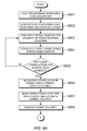
- Figure 5 illustrates a method of controlling a DSSS receiver, according to an embodiment of the present invention.
- the method can be performed by, for example, the apparatus shown in Fig. 2 .
- step S501 DSSS acquisition is performed to obtain initial estimates of a frequency offset and a spreading code phase, by correlating the input I and Q samples to the code samples.
- step S502 correlation functions are sequentially obtained for each one of a plurality of segments of the received DSSS signal.
- step S503 DSSS tracking is performed by comparing the phase and position of a correlation peak in one of the obtained correlation functions to a previous phase and position of the correlation peak.
- Figure 6 illustrates apparatus for demodulating a DSSS signal, according to an embodiment of the present invention.
- the apparatus includes an acquisition correlator 610 and a tracking correlator 620 similar to the acquisition correlator 210 and tracking correlator 220 of Fig. 2 .
- the apparatus of the present embodiment further comprises a DSSS carrier tracking part 630-1 and a DSSS code tracking part 630-2.
- ADC samples of the received DSSS signal are collected from a hardware receiving section, buffered, and passed to the logical receiving channels.
- GNSS receivers which must track a number of satellites (e.g. 30 satellites)
- each logical receiving channel tracks a different one of the satellites, using the PRN code of the corresponding satellite.
- the received signal is a GPS signal which is Doppler-shifted due to motion of the satellite relative to the receiver.
- Doppler frequency offsets in GNSS signals can, for example, be up to ⁇ 5 kilohertz (kHz).
- ADC samples corresponding to a segment of the received DSSS signal are applied to the FFT-based tracking correlator 620.
- the segment, on which correlation is to be performed, can have a duration of a fraction or multiple PRN sequences.
- the PRN spreading code is periodic with a repeat period of 1 ms, and samples of a 1 ms segment of the received DSSS signal, corresponding to the duration of one spreading code repeat period, are input to the tracking correlator 620.
- samples of a local replica of the spreading code to be processed by the receiving channel are generated or obtained from a data store. If necessary, the replica spreading code is converted to the same sampling frequency as the ADC input signal samples.
- the tracking correlator 620 performs a FFT and takes the conjugate of the complex output of the FFT for the replica spreading code. The process of sampling the replica spreading code, performing an FFT and taking the complex conjugate does not have to be performed during every correlation, and can, for example, be performed once at start-up or stored pre-processed in a memory.
- the correlation function is output to the carrier tracking part 630-1.
- one receiving channel is illustrated, which performs DSSS tracking for one satellite out of a plurality of satellites.
- the initial transform (e.g. FFT) part of the correlation process can be shared amongst the receiving channels for all satellites, which significantly reduces the processing needs of the receiver. This reduces the processing load, since samples from each segment of the received signal to be correlated only have to be transformed once, and can then be shared with each receiving channel.
- the carrier tracking part 630-1 uses the phase of the peak correlation bin as input to a phase tracking filter.
- the correlation function is input to a phase correcting module 631 which applies a phase correction, for example by multiplying the correlation function by e -j ⁇ to apply a phase rotation.
- a detecting module 632 detects the phase of the correlation peak in the corrected correlation function.
- the phase value of the correlation peak is fed into a loop filter 633, which could for example be a standard PLL loop or a Kalman filter, and the output of the loop filter 633 is used to control the phase correcting module 631. Therefore the applied phase correction can be updated based on the detected phase of the correlation peak.
- the peak position is characterised by the code phase bin at which the correlation peak exists relative to the PRN code phase.
- the peak detecting module 632 can be provided with the index (I) of the correlation bin in which the correlation peak was found during the acquisition process, which is the most likely location of the signal correlation peak.
- the peak bin index (I) can be included in the acquisition parameters stored by the acquisition correlator 610 when the correlation process is successfully completed.
- the accuracy of correlation peak tracking can be further improved by using interpolation over the code phase bins to include fractional offsets. By taking a number of successive correlation peak estimates and performing a linear regression over them, an estimate of the code phase can be made over time. Kalman filters can also be included in the correlation peak tracking, if required.
- phase tracking loop applies a phase correction to the output correlation function, as opposed to prior art designs which control the local oscillator which generates the I and Q signal components (see Fig. 1 ), the phase tracking loop is decoupled from the correlation process.
- phase value of the correlation peak detected by the peak detecting module 632 is input to a symbol/data estimation module 634, which estimates the current value of the symbol/data with which the received DSSS signal is modulated.
- a symbol/data estimation module 634 estimates the current value of the symbol/data with which the received DSSS signal is modulated.
- the symbol/data estimation module 634 controls a symbol/data removing module 635 to remove the symbol/data from the correlation function, after the carrier phase tracking loop. This provides a coherent correlation function which can be output to the code tracking part 630-2.
- the correlation process can be extended after applying carrier correction, by integrating a plurality of complex correlation functions. This will be described in more detail below.
- the symbol polarity estimates can be used to determine the receiver navigation data in a GNSS receiver. This can be done simply by finding the synchronisation word which gives the polarity of the symbols and the alignment for the convolutional FEC or the data itself.
- the code tracking part 630-2 receives the coherent correlation function.
- a peak code phase calculating module 636 calculates the code phase of the correlation peak, including a fractional offset.
- the code phase is input to a code tracking filter 637 which provides an estimate of the code phase over time, for use in code tracking.
- any deviation of the current peak relative to a previous position of the peak provides the change in the code phase, which is itself an indication of the presence of Doppler frequency offset, for example due to satellite movement.
- multiple complex correlations are coherently summed in a peak alignment and summing module 638.
- the peak alignment and summing module 638 checks the current position of the correlation peak against a previous position of the correlation peak to determine whether the peak location has moved. If the correlation peak has moved, the new correlation function is shifted to ensure the correlation function is aligned before summing. After being phase aligned, successive correlation functions can be coherently summed to give an integrated correlation function. Aligning and summing correlation functions in this way can increase the integration time, providing enhanced signal recovery.
- the output integrated correlation function can be used for various aspects of signal monitoring, including signal quality monitoring (e.g. deformation in the transmitted signal), multipath detection and mitigation, side lobe rejection, spoofing rejection, narrow band interference rejections, meaconing detection and tracking, and/or multi-antenna optimal combining.
- signal quality monitoring e.g. deformation in the transmitted signal
- multipath detection and mitigation e.g., multipath detection and mitigation
- side lobe rejection e.g. deformation in the transmitted signal
- spoofing rejection e.g. spoofing rejection
- narrow band interference rejections e.g., narrow band interference rejection, meaconing detection and tracking, and/or multi-antenna optimal combining.
- Figures 7A and 7B illustrates a DSSS acquisition process using the transformed domain based correlation method, according to an embodiment of the present invention.
- the method can be used to perform correlation successively over an expected range of Doppler frequency offsets to be searched, over a plurality of spreading codes, and over a plurality of data segments.
- the method can be used by the acquisition correlators of Figs. 2 and 6 to acquire a DSSS signal.
- the transformed domain based correlation method is a FFT-based method similar to the one described above with reference to Fig. 3 , but it will be understood that the invention is not limited to FFT-based methods and other transform functions can be used.
- step S701 the acquisition correlator loads the I and Q samples for a predetermined number N of signal segments, which are segments of the received DSSS signal of predetermined length.
- each segment can have the duration of one repeat period of the spreading code.
- step S702 a FFT is applied to the I and Q samples for all the signal segments which can be shared with other parallel acquisition or tracking processes.
- a FFT is applied to the I and Q samples for all the signal segments which can be shared with other parallel acquisition or tracking processes.
- the transformed I and Q samples can be shared with the other receiving channels.
- step S703 samples of the complex conjugate of the transformed spreading code to be searched are obtained.
- step S704 the acquisition process goes into a loop which tests each of the course Doppler offset possibilities.
- step S704 the FFT transformed samples of the signal are cyclically rotated over each of a plurality of Doppler frequency bins, each bin corresponding to a different Doppler frequency to be tested.
- step S705 a correlation function is obtained between the transformed I and Q samples and spreading code samples.
- the correlation function obtained in step S705 provides the correlation for the coarse Doppler offset being tested by the current Doppler bin (I).
- step S706 the correlation results for the N segments being processed are summed non-coherently, by summing the powers of the individual correlation results.
- step S707 it is checked whether the summed correlation peak is larger than any correlation peaks obtained for the other Doppler frequency bins that have already been tested. If a larger peak has already been found, then the process proceeds to step S709 and repeats until all of the Doppler frequency bins have been tested.
- the largest correlation peak obtained during this process for each segment is normally compared against a predetermined threshold to determine whether a signal has been detected.
- step S708 when the largest correlation peak has been found in step S707, then in step S708 the correlation functions obtained using the Doppler frequency bin (I) for the N segments are stored, together with the index (I) of the Doppler bin. Then, once all N segments have been processed, in step S710 a fine Doppler offset is estimated from changes in phase of the correlation peak. Then, in step S711 the correlation functions from all N segments are rotated to align the correlation functions in phase, and in step S712 the correlation functions are coherently added to obtain an integrated correlation function over all N segments. In step S713 it is checked whether the correlation peak is greater than a predetermined threshold.
- step S701 If the test fails, then the process returns to step S701 and loads I and Q samples for new set of signal segments. However, if the predetermined threshold is exceeded, then acquisition is successful. In step S714, the acquisition parameters are stored, and the process continues to the DSSS tracking stage. It should be noted that as this process uses coherent addition of the correlation functions from the segments of data it is significantly more sensitive than the conventional technique. It is possible to accurately find signals which would otherwise not be detectable, with the correct correlation location and fine Doppler estimation of less than one Hertz.
- phase of the correlation peak and coherently summing in the acquisition phase provides a significant improvement to the sensitivity of the acquisition process.
- Figures 8A and 8B illustrate a DSSS carrier tracking method, according to an embodiment of the present invention.
- the method can be performed, for example, by the apparatus of Figs. 2 or 6 .
- the method starts from the data acquired in an acquisition process, for example the process of Figs. 7A and 7B , and then successively refines the carrier phase and phase rate estimates for each correlation function prior to summation. This allows each correlation function to be accurately aligned prior to summation, with the result that very long integration times can be achieved.
- step S801 the acquisition parameters, including the peak correlation location and Doppler frequency offset which were determined during acquisition, are loaded. Then, in step S802 the transformed spreading code sequences to be correlated are loaded, and in step S803 input signal samples for a segment of predetermined duration are loaded.
- the predetermined duration may be referred to as the primary correlation period.
- step S804 the tracking correlation process is performed using a Time and Frequency Transform based correlation method as described above with reference to Fig. 3 .
- the process continues to perform correlations for successive segments of the received DSSS signal until it is determined in step S805 that a sufficient number of correlations have been obtained to cover a predetermined number of data symbols.
- the DSSS signal may be transmitted with a data symbol duration which is similar to the spreading code repeat period, or which is much greater than the spreading code repeat period.
- steps S801 to S805 are performed by the tracking correlator 620.
- step S806 each of the correlation functions is aligned in phase to the other correlation functions using the current estimate of the Doppler frequency offset value.
- step S806 is performed by the phase corrector 631.
- step S807 the aligned correlation functions from one data symbol are summed, and the symbol polarity is estimated.
- Step S807 corresponds to the functions performed by the phase corrector 631 in Fig. 6 , which aligns the correlation functions by applying phase corrections, and by the symbol/data estimator 634, which estimates the symbol polarity.
- step S808 the polarity of the data symbol is removed.
- step S808 is performed by the symbol/data removing module 635.
- step S809 a carrier phase tracking algorithm is used to remove any residual phase offset from a plurality of the correlation functions, and to update the Doppler estimate.
- Step S809 corresponds to the function of the loop filter 633 in Fig. 6 .
- step S810 the correlation functions across the predetermined number of data symbols can be summed to obtain an integrated correlation function.
- step S811 the new correlation peak location is updated, interpolation is used to obtain a fractional sample offset, and the integrated correlation function, new peak location and fractional offset are stored. Steps S810 and S811 correspond to the functions performed by the peak code phase calculating module 636 and the code tracking filter 637 of Fig. 6 .
- step S812 it is checked whether there are a sufficient number of integrated correlation functions to perform a final integration.
- a second predetermined number of integrated correlation functions may be required. If there are insufficient integrated correlation functions, the process returns to step S803 and continues until a sufficient number are available, and then proceeds to step S813.
- step S813 each of the stored integrated correlation functions is phase-rotated to align the peaks in different ones of the integrated correlation functions, allowing the integrated correlation functions to be coherently summed.
- step S813 is performed by the peak alignment and summing module 638.
- step S814 the code phase over time is estimated using a curve fitting technique, for example linear regression.
- steps S812 and S813 can be omitted, and step S814 can be performed directly on the integrated correlation function obtained in step S810.
- the received DSSS signal may be Binary Phase Shift Keying (BPSK) modulated with data bits
- BPSK Binary Phase Shift Keying
- the primary correlation period can be selected in consideration of the duration of one data bit. If there is a phase transition during a correlation period, part of the integration will be performed with one symbol polarity and the rest of the integration will be performed with the opposite polarity. In the worst case scenario, the transition occurs halfway through the correlation period, producing no overall correlation.
- BPSK Binary Phase Shift Keying
- the data period is much longer than the correlation period, this is not a significant problem.
- the data rate is 50 bits per second (bps), and so the duration of each data bit is 20 ms.
- the correlation period is the same as the PRN spreading code repeat period, which is 1 ms for GPS, the maximum loss that can result from a data transition is 1/20 th of the signal amplitude, equivalent to less than 0.5 dB. That is, when a total of 20 correlation functions each corresponding to a 1 ms segment are summed to obtained an integrated correlation function across one data symbol, corresponding to a 20 ms portion of the received signal, at most one of the 20 correlation functions will include a data transition.
- the data symbol period may be similar to the spreading code repeat period.
- the symbol period is the same as the PRN length.
- the primary correlation period should preferably be chosen to have a length which is a predetermined fraction of the PRN repeat period. This provides the advantage that the probability of a data transition occurring in any given segment is reduced. At low signal to noise ratios (SNR), the use of such short segments may mean that several correlation functions need to be summed before being input into the phase tracking algorithm, which in turn may require a good estimation of the Doppler frequency offset.
- SNR signal to noise ratios
- Embodiments of the invention have been described in which a Time and Frequency Transform based correlation process is used to obtain a correlation function during DSSS tracking.
- the correlation function can be used as input into a phase tracking algorithm, with the error being used to correct the correlation function.
- An advantage of this approach is the decoupling of the primary correlation function (e.g. the tracking correlators of Figs. 2 or 6 ) from the carrier loop. This provides a more robust tracking process which is less sensitive to the carrier tracking estimates, allowing the receiver to track in very low signal to noise environments.
- the Doppler frequency offsets can be as much as ⁇ 5 kHz. In this scenario, if the FFT correlation is performed over 1 ms intervals, for example, the FFT bins will be 1KHz.
- the coarse Doppler frequency offset should be removed from the sampled data in the frequency domain, before multiplication with the complex conjugate of the transform of the reference PRN.
- the frequency resolution of the initial Fourier transform is increased by zero-padding the sampled signal, and increasing the reference length accordingly.
- the correlation phase change can be limited to ⁇ /2 or less. This gives a worst-case scenario in which there is a phase change of ⁇ /2 between successive correlation functions, resulting in approximately 1dB of implementation loss. Therefore the maximum loss can be improved by the use of zero-padding to increase the frequency resolution of the FFT.
- the DSSS receiver may include two or more separate antenna, RF chains and IF sampling channels.
- the receiver can be arranged to time-align the correlation functions from different antennas, and coherently sum the time-aligned correlation functions from the different antennas. This allows the outputs of each antenna to be combined coherently when the antennas are tracking the same signal source, which can provide significant improvements in the presence of interference.
- the receiver should time-align the integration functions between the two or more sources to at least the nearest primary correlation moment, or better still to the nearest chip.
- the signal-to-noise ratio (SNR) of each antenna can be detected, and the correlation functions can be weighted before summing to give an optimum combination, for example by applying a larger weighting to correlation functions from an antenna with a high SNR.
- SNR signal-to-noise ratio
Priority Applications (7)
| Application Number | Priority Date | Filing Date | Title |
|---|---|---|---|
| EP13275134.8A EP2811320A1 (de) | 2013-06-05 | 2013-06-05 | Empfänger und Verfahren für Direktsequenz-Spreizspektrum-Signale |
| PCT/GB2014/051738 WO2014195712A1 (en) | 2013-06-05 | 2014-06-05 | Receiver and method for direct sequence spread spectrum signals |
| CA2915313A CA2915313C (en) | 2013-06-05 | 2014-06-05 | Receiver and method for direct sequence spread spectrum signals |
| JP2016517682A JP6447883B2 (ja) | 2013-06-05 | 2014-06-05 | 直接シーケンススペクトラム拡散信号のための受信機及び方法 |
| US14/896,650 US10281584B2 (en) | 2013-06-05 | 2014-06-05 | Receiver and method for direct sequence spread spectrum signals |
| ES14731763T ES2828638T3 (es) | 2013-06-05 | 2014-06-05 | Receptor y procedimiento para señales de espectro ensanchado de secuencia directa |
| EP14731763.0A EP3004928B1 (de) | 2013-06-05 | 2014-06-05 | Empfänger und verfahren für direktsequenz-spreizspektrum-signale |
Applications Claiming Priority (1)
| Application Number | Priority Date | Filing Date | Title |
|---|---|---|---|
| EP13275134.8A EP2811320A1 (de) | 2013-06-05 | 2013-06-05 | Empfänger und Verfahren für Direktsequenz-Spreizspektrum-Signale |
Publications (1)
| Publication Number | Publication Date |
|---|---|
| EP2811320A1 true EP2811320A1 (de) | 2014-12-10 |
Family
ID=48570029
Family Applications (2)
| Application Number | Title | Priority Date | Filing Date |
|---|---|---|---|
| EP13275134.8A Ceased EP2811320A1 (de) | 2013-06-05 | 2013-06-05 | Empfänger und Verfahren für Direktsequenz-Spreizspektrum-Signale |
| EP14731763.0A Active EP3004928B1 (de) | 2013-06-05 | 2014-06-05 | Empfänger und verfahren für direktsequenz-spreizspektrum-signale |
Family Applications After (1)
| Application Number | Title | Priority Date | Filing Date |
|---|---|---|---|
| EP14731763.0A Active EP3004928B1 (de) | 2013-06-05 | 2014-06-05 | Empfänger und verfahren für direktsequenz-spreizspektrum-signale |
Country Status (6)
| Country | Link |
|---|---|
| US (1) | US10281584B2 (de) |
| EP (2) | EP2811320A1 (de) |
| JP (1) | JP6447883B2 (de) |
| CA (1) | CA2915313C (de) |
| ES (1) | ES2828638T3 (de) |
| WO (1) | WO2014195712A1 (de) |
Cited By (15)
| Publication number | Priority date | Publication date | Assignee | Title |
|---|---|---|---|---|
| CN105717518A (zh) * | 2016-01-27 | 2016-06-29 | 南京师范大学 | 一种基于码相位辨识的卫星接收机欺骗信号检测方法 |
| WO2016130399A1 (en) | 2015-02-09 | 2016-08-18 | Concentric Real Time, Llc | Radio receiver for determining location of a signal source |
| CN107255823A (zh) * | 2017-06-20 | 2017-10-17 | 北京遥测技术研究所 | 一种载体多天线可用导航卫星信号的产生方法 |
| EP3293548A1 (de) * | 2016-09-08 | 2018-03-14 | Airbus Defence and Space Limited | Vorrichtung und verfahren zum erhalt einer korrelationsfunktion im frequenzbereich |
| CN110114696A (zh) * | 2016-12-15 | 2019-08-09 | 深圳开阳电子股份有限公司 | 用于卫星导航系统的信号捕获方法及接收机 |
| CN110231633A (zh) * | 2019-05-15 | 2019-09-13 | 西安交通大学 | 一种信号捕获阶段基于lstm的gnss欺骗式干扰识别、抑制方法及系统 |
| CN111158023A (zh) * | 2019-12-27 | 2020-05-15 | 中国人民解放军军事科学院国防科技创新研究院 | 基于低轨卫星的接收机终端抗干扰方法 |
| CN111257913A (zh) * | 2019-11-29 | 2020-06-09 | 交通运输部长江通信管理局 | 北斗卫星信号捕获方法以及装置 |
| CN111628816A (zh) * | 2019-01-03 | 2020-09-04 | 长沙天仪空间科技研究院有限公司 | 一种卫星通信系统的窄带干扰抑制方法 |
| CN112367098A (zh) * | 2020-11-10 | 2021-02-12 | 南京航空航天大学 | 一种通过扩频载波实现故障诊断的方法 |
| US10942279B2 (en) | 2017-10-25 | 2021-03-09 | Samsung Electronics Co., Ltd | System and method for improved GNSS sensitivity via combining acquisition and track correlation hypotheses |
| CN114584174A (zh) * | 2022-01-22 | 2022-06-03 | 北京睿信丰科技有限公司 | 基于频域聚焦与合成傅里叶变换的信号捕获方法 |
| CN115037331A (zh) * | 2022-08-10 | 2022-09-09 | 中国电子科技集团公司第十研究所 | 一种基于逆向外推的异步突发信号定时同步方法 |
| CN115940992A (zh) * | 2022-11-16 | 2023-04-07 | 中国人民解放军战略支援部队航天工程大学 | 一种基于频域子空间原理的bl-dsss信号码跟踪方法 |
| CN111257913B (zh) * | 2019-11-29 | 2024-04-30 | 交通运输部长江通信管理局 | 北斗卫星信号捕获方法以及装置 |
Families Citing this family (28)
| Publication number | Priority date | Publication date | Assignee | Title |
|---|---|---|---|---|
| CN104614740B (zh) | 2015-02-10 | 2016-08-17 | 华中科技大学 | 一种导航信号数据导频联合跟踪方法及装置 |
| US10048385B2 (en) | 2015-10-12 | 2018-08-14 | Deere & Company | Satellite navigation receiver with fixed point sigma RHO filter |
| CN105471470B (zh) * | 2015-11-18 | 2018-02-02 | 东南大学 | 基于判决反馈的扩频信号频率偏移估计方法 |
| CN105656511B (zh) * | 2016-01-20 | 2020-04-07 | 上海物联网有限公司 | 一种适应于有频偏和低信噪比环境下的差分相关捕获方法 |
| CN107204945B (zh) * | 2016-03-18 | 2020-11-03 | 富士通株式会社 | 频差估计装置、信道间隔估计装置、方法和系统 |
| CA3016332A1 (en) * | 2016-05-20 | 2017-11-23 | Myriota Pty Ltd | Position estimation in a low earth orbit satellite communications system |
| EP3282287A1 (de) * | 2016-08-11 | 2018-02-14 | Airbus Defence and Space GmbH | Verbesserung des empfangs von spreizspektrumsignalen |
| KR101720327B1 (ko) * | 2016-10-28 | 2017-03-28 | 한국지질자원연구원 | 수중 이상체의 위치 측정 장치 및 방법 |
| HUE062471T2 (hu) * | 2017-02-24 | 2023-11-28 | Neosat Gmbh | Ortogonális korrelációs jelek detektálása és szinkronizálása alacsony SNR mellett |
| CN108600134B (zh) * | 2018-04-23 | 2020-01-17 | 北京邮电大学 | 一种载波跟踪方法及装置 |
| US20190346548A1 (en) * | 2018-05-11 | 2019-11-14 | GM Global Technology Operations LLC | Filtering to address range walk effect in range-doppler map |
| US10735046B1 (en) * | 2019-10-10 | 2020-08-04 | United States Government As Represented By The Secretary Of The Navy | Method of spread code acquisition using phase multiplexed shuffled correlation and concurrent two parameter alignment screening |
| US11604285B2 (en) * | 2020-04-22 | 2023-03-14 | Topcon Positioning Systems, Inc. | Method and apparatus for receiving chip-by-chip multiplexed CSK signals |
| CN111538054B (zh) * | 2020-05-20 | 2022-06-10 | 南京大鱼半导体有限公司 | 确定卫星有效性的方法、装置、存储介质及接收机 |
| CN111610539A (zh) * | 2020-06-04 | 2020-09-01 | 桂林电子科技大学 | 基于分段重构的BOC(n,n)信号捕获方法及装置 |
| CN112649819A (zh) * | 2020-11-24 | 2021-04-13 | 中国科学院国家空间科学中心 | 一种高动态扩频信号捕获装置及捕获方法 |
| CN112803968B (zh) * | 2020-12-30 | 2021-07-30 | 南京天际易达通信技术有限公司 | 一种无人机机载测控方法 |
| CN112910499B (zh) * | 2021-02-10 | 2022-04-01 | 西南电子技术研究所(中国电子科技集团公司第十研究所) | 扩频信号精确捕获系统 |
| CN113328765B (zh) * | 2021-04-25 | 2022-07-26 | 北京航空航天大学 | 一种高动态下多种扩频体制通用接收机的实现方法 |
| CN113452403B (zh) * | 2021-08-31 | 2022-01-21 | 北京理工大学 | 多载波相干捕获方法、装置、电子设备及存储介质 |
| CN114024625B (zh) * | 2021-11-10 | 2024-01-02 | 上海无线电设备研究所 | 高精度并行码相位测量方法 |
| CN114156949A (zh) * | 2021-11-30 | 2022-03-08 | 中冶南方都市环保工程技术股份有限公司 | 一种单相光伏同步的方法及系统 |
| CN114221674B (zh) * | 2021-12-06 | 2023-08-11 | 西北工业大学 | 一种扩频信号速率自适应捕获方法 |
| KR102546205B1 (ko) * | 2022-01-21 | 2023-06-21 | 엘아이지넥스원 주식회사 | 순환 주파수 추정 기반 직접 시퀀스 확산 스펙트럼 신호 탐지 방법 및 그를 위한 장치 |
| CN114884585A (zh) * | 2022-04-12 | 2022-08-09 | 中国电子科技集团公司第十研究所 | 多维联合决策的转发式干扰感知与防护方法及装置 |
| CN115267860B (zh) * | 2022-09-27 | 2022-12-27 | 中国人民解放军国防科技大学 | 一种高动态短突发信号的多相关器组高精度引导方法 |
| CN115499036B (zh) * | 2022-11-14 | 2023-02-24 | 北京航空航天大学合肥创新研究院(北京航空航天大学合肥研究生院) | 宽带扩频信号并行捕获方法及存储介质 |
| KR102644715B1 (ko) * | 2022-11-30 | 2024-03-11 | (주)마이크로인피니티 | 위성 신호 획득 장치 및 방법 |
Citations (4)
| Publication number | Priority date | Publication date | Assignee | Title |
|---|---|---|---|---|
| US4578678A (en) * | 1983-11-14 | 1986-03-25 | The United States Of America As Represented By The United States National Aeronautics And Space Administration | High dynamic global positioning system receiver |
| EP1143674A2 (de) * | 2000-04-06 | 2001-10-10 | Nokia Mobile Phones Ltd. | Frequenzversatzuntersuchung in einem CDMA-Empfänger |
| US20030215005A1 (en) * | 2002-05-16 | 2003-11-20 | Nokia Corporation | Method for synchronizing a receiver, a system, and an electronic device |
| US20040138811A1 (en) * | 2002-02-25 | 2004-07-15 | Koichiro Teranishi | Gps receiver apparatus and receiving method |
Family Cites Families (17)
| Publication number | Priority date | Publication date | Assignee | Title |
|---|---|---|---|---|
| US5271034A (en) * | 1991-08-26 | 1993-12-14 | Avion Systems, Inc. | System and method for receiving and decoding global positioning satellite signals |
| GB2343801B (en) * | 1997-08-21 | 2001-09-12 | Data Fusion Corp | Method and apparatus for acquiring wide-band pseudorandom noise encoded waveforms |
| FI19992653A (fi) * | 1999-12-09 | 2001-06-10 | Nokia Mobile Phones Ltd | Menetelmä vastaanottimen tahdistamiseksi ja vastaanotin |
| US6407699B1 (en) * | 2000-04-14 | 2002-06-18 | Chun Yang | Method and device for rapidly extracting time and frequency parameters from high dynamic direct sequence spread spectrum radio signals under interference |
| JP4120237B2 (ja) * | 2002-02-28 | 2008-07-16 | ソニー株式会社 | 復調装置及び受信装置 |
| US8098765B1 (en) * | 2004-02-23 | 2012-01-17 | Sirf Technology, Inc. | Reducing and sharing computations for GPS signal processing |
| JP4154609B2 (ja) * | 2004-07-30 | 2008-09-24 | ソニー株式会社 | 衛星信号受信処理装置および衛星信号受信処理方法 |
| US7639181B2 (en) * | 2005-07-01 | 2009-12-29 | Sirf Technology Holdings, Inc. | Method and device for tracking weak global navigation satellite system (GNSS) signals |
| US7471241B1 (en) * | 2005-07-25 | 2008-12-30 | Chun Yang | Global navigation satellite system (GNSS) receivers based on satellite signal channel impulse response |
| FR2892202B1 (fr) * | 2005-10-14 | 2007-11-30 | Thales Sa | Recepteur gnss a precision amelioree utilisant deux porteuses de signal |
| JP4229169B2 (ja) * | 2006-10-26 | 2009-02-25 | セイコーエプソン株式会社 | 測位装置、電子機器及びプログラム |
| JP4264584B2 (ja) * | 2007-04-20 | 2009-05-20 | ソニー株式会社 | 搬送波同期回路および搬送波同期方法 |
| US8331422B2 (en) * | 2008-02-28 | 2012-12-11 | Magellan Systems Japan, Inc. | Method and apparatus for acquisition, tracking, and transfer using sub-microsecond time transfer using weak GPS/GNSS signals |
| US7940834B2 (en) * | 2008-05-15 | 2011-05-10 | Trimble Navigation Limited | Signal receiver using data bit search in alternating time segments |
| JP5765902B2 (ja) * | 2010-09-07 | 2015-08-19 | 日本無線株式会社 | 衛星信号のコード追尾装置 |
| FI122637B (fi) * | 2011-04-28 | 2012-04-30 | Fastrax Ltd | Signaalinkäsittelymenetelmä, -laite ja -järjestelmä |
| WO2013016800A1 (en) * | 2011-07-29 | 2013-02-07 | Baseband Technologies Inc. | System, method, and computer program for a low power and low cost gnss receiver |
-
2013
- 2013-06-05 EP EP13275134.8A patent/EP2811320A1/de not_active Ceased
-
2014
- 2014-06-05 CA CA2915313A patent/CA2915313C/en active Active
- 2014-06-05 US US14/896,650 patent/US10281584B2/en active Active
- 2014-06-05 ES ES14731763T patent/ES2828638T3/es active Active
- 2014-06-05 EP EP14731763.0A patent/EP3004928B1/de active Active
- 2014-06-05 JP JP2016517682A patent/JP6447883B2/ja active Active
- 2014-06-05 WO PCT/GB2014/051738 patent/WO2014195712A1/en active Application Filing
Patent Citations (4)
| Publication number | Priority date | Publication date | Assignee | Title |
|---|---|---|---|---|
| US4578678A (en) * | 1983-11-14 | 1986-03-25 | The United States Of America As Represented By The United States National Aeronautics And Space Administration | High dynamic global positioning system receiver |
| EP1143674A2 (de) * | 2000-04-06 | 2001-10-10 | Nokia Mobile Phones Ltd. | Frequenzversatzuntersuchung in einem CDMA-Empfänger |
| US20040138811A1 (en) * | 2002-02-25 | 2004-07-15 | Koichiro Teranishi | Gps receiver apparatus and receiving method |
| US20030215005A1 (en) * | 2002-05-16 | 2003-11-20 | Nokia Corporation | Method for synchronizing a receiver, a system, and an electronic device |
Non-Patent Citations (1)
| Title |
|---|
| JIANHUI WANG ET AL: "Two-stage FFT acquisition method of weak GNSS signals", COMPUTER SCIENCE AND NETWORK TECHNOLOGY (ICCSNT), 2012 2ND INTERNATIONAL CONFERENCE ON, IEEE, 29 December 2012 (2012-12-29), pages 1918 - 1921, XP032420205, ISBN: 978-1-4673-2963-7, DOI: 10.1109/ICCSNT.2012.6526294 * |
Cited By (26)
| Publication number | Priority date | Publication date | Assignee | Title |
|---|---|---|---|---|
| US10416278B2 (en) | 2015-02-09 | 2019-09-17 | Concentric Real Time, Llc | Radio receiver for determining location of a signal source |
| WO2016130399A1 (en) | 2015-02-09 | 2016-08-18 | Concentric Real Time, Llc | Radio receiver for determining location of a signal source |
| EP3256876B1 (de) * | 2015-02-09 | 2021-05-05 | Concentric Real Time, LLC | Funkempfänger zur bestimmung der position einer signalquelle |
| EP3256876A4 (de) * | 2015-02-09 | 2018-10-03 | Concentric Real Time, LLC | Funkempfänger zur bestimmung der position einer signalquelle |
| CN105717518B (zh) * | 2016-01-27 | 2017-11-07 | 南京师范大学 | 一种基于码相位辨识的卫星接收机欺骗信号检测方法 |
| CN105717518A (zh) * | 2016-01-27 | 2016-06-29 | 南京师范大学 | 一种基于码相位辨识的卫星接收机欺骗信号检测方法 |
| EP3293548A1 (de) * | 2016-09-08 | 2018-03-14 | Airbus Defence and Space Limited | Vorrichtung und verfahren zum erhalt einer korrelationsfunktion im frequenzbereich |
| WO2018046694A1 (en) * | 2016-09-08 | 2018-03-15 | Airbus Defence And Space Limited | Apparatus and methods for obtaining a correlation function in the frequency domain |
| AU2017324466B2 (en) * | 2016-09-08 | 2021-11-18 | Airbus Defence And Space Limited | Apparatus and methods for obtaining a correlation function in the frequency domain |
| CN110114696B (zh) * | 2016-12-15 | 2023-01-13 | 深圳开阳电子股份有限公司 | 用于卫星导航系统的信号捕获方法及接收机 |
| CN110114696A (zh) * | 2016-12-15 | 2019-08-09 | 深圳开阳电子股份有限公司 | 用于卫星导航系统的信号捕获方法及接收机 |
| CN107255823A (zh) * | 2017-06-20 | 2017-10-17 | 北京遥测技术研究所 | 一种载体多天线可用导航卫星信号的产生方法 |
| US10942279B2 (en) | 2017-10-25 | 2021-03-09 | Samsung Electronics Co., Ltd | System and method for improved GNSS sensitivity via combining acquisition and track correlation hypotheses |
| US11686854B2 (en) | 2017-10-25 | 2023-06-27 | Samsung Electronics Co., Ltd | System and method for improved GNSS sensitivity via combining acquisition and track correlation hypotheses |
| CN111628816A (zh) * | 2019-01-03 | 2020-09-04 | 长沙天仪空间科技研究院有限公司 | 一种卫星通信系统的窄带干扰抑制方法 |
| CN111628816B (zh) * | 2019-01-03 | 2022-02-01 | 长沙天仪空间科技研究院有限公司 | 一种卫星通信系统的窄带干扰抑制方法 |
| CN110231633B (zh) * | 2019-05-15 | 2021-05-28 | 西安交通大学 | 一种信号捕获阶段基于lstm的gnss欺骗式干扰识别、抑制方法及系统 |
| CN110231633A (zh) * | 2019-05-15 | 2019-09-13 | 西安交通大学 | 一种信号捕获阶段基于lstm的gnss欺骗式干扰识别、抑制方法及系统 |
| CN111257913A (zh) * | 2019-11-29 | 2020-06-09 | 交通运输部长江通信管理局 | 北斗卫星信号捕获方法以及装置 |
| CN111257913B (zh) * | 2019-11-29 | 2024-04-30 | 交通运输部长江通信管理局 | 北斗卫星信号捕获方法以及装置 |
| CN111158023A (zh) * | 2019-12-27 | 2020-05-15 | 中国人民解放军军事科学院国防科技创新研究院 | 基于低轨卫星的接收机终端抗干扰方法 |
| CN112367098A (zh) * | 2020-11-10 | 2021-02-12 | 南京航空航天大学 | 一种通过扩频载波实现故障诊断的方法 |
| CN114584174A (zh) * | 2022-01-22 | 2022-06-03 | 北京睿信丰科技有限公司 | 基于频域聚焦与合成傅里叶变换的信号捕获方法 |
| CN115037331A (zh) * | 2022-08-10 | 2022-09-09 | 中国电子科技集团公司第十研究所 | 一种基于逆向外推的异步突发信号定时同步方法 |
| CN115940992A (zh) * | 2022-11-16 | 2023-04-07 | 中国人民解放军战略支援部队航天工程大学 | 一种基于频域子空间原理的bl-dsss信号码跟踪方法 |
| CN115940992B (zh) * | 2022-11-16 | 2023-10-03 | 中国人民解放军战略支援部队航天工程大学 | 一种基于频域子空间原理的bl-dsss信号码跟踪方法 |
Also Published As
| Publication number | Publication date |
|---|---|
| CA2915313C (en) | 2022-03-29 |
| ES2828638T3 (es) | 2021-05-27 |
| JP6447883B2 (ja) | 2019-01-09 |
| CA2915313A1 (en) | 2014-12-11 |
| US20160116599A1 (en) | 2016-04-28 |
| JP2016524710A (ja) | 2016-08-18 |
| US10281584B2 (en) | 2019-05-07 |
| EP3004928B1 (de) | 2020-10-07 |
| WO2014195712A1 (en) | 2014-12-11 |
| EP3004928A1 (de) | 2016-04-13 |
Similar Documents
| Publication | Publication Date | Title |
|---|---|---|
| EP3004928B1 (de) | Empfänger und verfahren für direktsequenz-spreizspektrum-signale | |
| US9223028B2 (en) | System and method for fast code phase and carrier frequency acquisition in GPS receiver | |
| US7010066B2 (en) | System and method for fast code phase and carrier frequency acquisition in GPS receiver | |
| CN105917622B (zh) | 用于接收复合信号的方法和接收器 | |
| JP4754783B2 (ja) | Gps信号をトラッキングするオープンループに関する方法 | |
| US7982668B2 (en) | Method for processing combined navigation signals | |
| US7231095B2 (en) | Spread spectrum signal demodulation method and apparatus | |
| US7693211B2 (en) | Fast fourier transform based phase locked loop for navigational receivers | |
| US8462616B2 (en) | Apparatus and method for estimating a frequency shift and a time shift | |
| CN108226967B (zh) | Gnss信号跟踪方法及装置 | |
| WO2006092641A1 (en) | Acquisition of a wireless reverse link signal affected by doppler frequency drift |
Legal Events
| Date | Code | Title | Description |
|---|---|---|---|
| PUAI | Public reference made under article 153(3) epc to a published international application that has entered the european phase |
Free format text: ORIGINAL CODE: 0009012 |
|
| 17P | Request for examination filed |
Effective date: 20130605 |
|
| AK | Designated contracting states |
Kind code of ref document: A1 Designated state(s): AL AT BE BG CH CY CZ DE DK EE ES FI FR GB GR HR HU IE IS IT LI LT LU LV MC MK MT NL NO PL PT RO RS SE SI SK SM TR |
|
| AX | Request for extension of the european patent |
Extension state: BA ME |
|
| STAA | Information on the status of an ep patent application or granted ep patent |
Free format text: STATUS: THE APPLICATION HAS BEEN REFUSED |
|
| 18R | Application refused |
Effective date: 20160616 |