EP1143674A2 - Frequenzversatzuntersuchung in einem CDMA-Empfänger - Google Patents
Frequenzversatzuntersuchung in einem CDMA-Empfänger Download PDFInfo
- Publication number
- EP1143674A2 EP1143674A2 EP01660058A EP01660058A EP1143674A2 EP 1143674 A2 EP1143674 A2 EP 1143674A2 EP 01660058 A EP01660058 A EP 01660058A EP 01660058 A EP01660058 A EP 01660058A EP 1143674 A2 EP1143674 A2 EP 1143674A2
- Authority
- EP
- European Patent Office
- Prior art keywords
- frequency
- code
- matrix
- time
- phase
- Prior art date
- Legal status (The legal status is an assumption and is not a legal conclusion. Google has not performed a legal analysis and makes no representation as to the accuracy of the status listed.)
- Withdrawn
Links
Images


Classifications
-
- G—PHYSICS
- G01—MEASURING; TESTING
- G01S—RADIO DIRECTION-FINDING; RADIO NAVIGATION; DETERMINING DISTANCE OR VELOCITY BY USE OF RADIO WAVES; LOCATING OR PRESENCE-DETECTING BY USE OF THE REFLECTION OR RERADIATION OF RADIO WAVES; ANALOGOUS ARRANGEMENTS USING OTHER WAVES
- G01S19/00—Satellite radio beacon positioning systems; Determining position, velocity or attitude using signals transmitted by such systems
- G01S19/01—Satellite radio beacon positioning systems transmitting time-stamped messages, e.g. GPS [Global Positioning System], GLONASS [Global Orbiting Navigation Satellite System] or GALILEO
- G01S19/13—Receivers
- G01S19/24—Acquisition or tracking or demodulation of signals transmitted by the system
- G01S19/29—Acquisition or tracking or demodulation of signals transmitted by the system carrier including Doppler, related
-
- H—ELECTRICITY
- H04—ELECTRIC COMMUNICATION TECHNIQUE
- H04B—TRANSMISSION
- H04B1/00—Details of transmission systems, not covered by a single one of groups H04B3/00 - H04B13/00; Details of transmission systems not characterised by the medium used for transmission
- H04B1/69—Spread spectrum techniques
- H04B1/707—Spread spectrum techniques using direct sequence modulation
- H04B1/7073—Synchronisation aspects
- H04B1/7075—Synchronisation aspects with code phase acquisition
-
- H—ELECTRICITY
- H04—ELECTRIC COMMUNICATION TECHNIQUE
- H04L—TRANSMISSION OF DIGITAL INFORMATION, e.g. TELEGRAPHIC COMMUNICATION
- H04L27/00—Modulated-carrier systems
- H04L27/18—Phase-modulated carrier systems, i.e. using phase-shift keying
- H04L27/22—Demodulator circuits; Receiver circuits
- H04L27/227—Demodulator circuits; Receiver circuits using coherent demodulation
- H04L27/2271—Demodulator circuits; Receiver circuits using coherent demodulation wherein the carrier recovery circuit uses only the demodulated signals
- H04L27/2272—Demodulator circuits; Receiver circuits using coherent demodulation wherein the carrier recovery circuit uses only the demodulated signals using phase locked loops
-
- H—ELECTRICITY
- H04—ELECTRIC COMMUNICATION TECHNIQUE
- H04B—TRANSMISSION
- H04B2201/00—Indexing scheme relating to details of transmission systems not covered by a single group of H04B3/00 - H04B13/00
- H04B2201/69—Orthogonal indexing scheme relating to spread spectrum techniques in general
- H04B2201/707—Orthogonal indexing scheme relating to spread spectrum techniques in general relating to direct sequence modulation
- H04B2201/70715—Orthogonal indexing scheme relating to spread spectrum techniques in general relating to direct sequence modulation with application-specific features
-
- H—ELECTRICITY
- H04—ELECTRIC COMMUNICATION TECHNIQUE
- H04L—TRANSMISSION OF DIGITAL INFORMATION, e.g. TELEGRAPHIC COMMUNICATION
- H04L27/00—Modulated-carrier systems
- H04L27/0014—Carrier regulation
- H04L2027/0044—Control loops for carrier regulation
- H04L2027/0053—Closed loops
- H04L2027/0057—Closed loops quadrature phase
-
- H—ELECTRICITY
- H04—ELECTRIC COMMUNICATION TECHNIQUE
- H04L—TRANSMISSION OF DIGITAL INFORMATION, e.g. TELEGRAPHIC COMMUNICATION
- H04L27/00—Modulated-carrier systems
- H04L27/0014—Carrier regulation
- H04L2027/0044—Control loops for carrier regulation
- H04L2027/0063—Elements of loops
- H04L2027/0065—Frequency error detectors
Definitions
- the present invention relates to a method for performing acquisition in a receiver as set forth in the preamble of the appended claim 1.
- the present invention relates further to a location system as set forth in the preamble of the appended claim 8.
- the present invention relates further to a receiver as set forth in the preamble of the appended claim 15.
- the present invention relates also to an electronic device as set forth in the preamble of the appended claim 22.
- GPS system Global Positioning System
- satellites which at least 4, in some situations even 12, are simultaneously within the sight of a receiver.
- These satellites transmit information about satellites, e.g. Ephemeris data of the satellite as well as data on the time of the satellite.
- Ephemeris data of the satellite
- the receiver used for positioning infers its position normally in such a way that the receiver calculates the time of propagation of a signal transmitted simultaneously from several satellites in the positioning system to the receiver.
- the receiver must typically receive the signal of at least four satellites within its sight, in order to calculate the position.
- the modulation of these signals is performed with at least one pseudo sequence. This pseudo sequence is different for each satellite. As a result of the modulation, a code-modulated wideband signal is generated.
- the modulation technique used makes it possible in the receiver to separate the signals transmitted from different satellites, although the carrier frequencies used in the transmission are substantially the same. This modulation technique is called code division multiple access (CDMA).
- CDMA code division multiple access
- the pseudo sequence used is e.g. a so-called C/A code (Coarse/Acquisition code), which is the Gold code.
- C/A code Coarse/Acquisition code
- Each GPS satellite transmits a signal by using an individual C/A code.
- the codes are formed as a modulo-2 sum of two 1023-bit binary sequences.
- the first binary sequence G1 is formed with a polynome X 10 + X 3 + 1
- the second binary sequence G2 is formed by delaying the polynome X 10 + X 9 + X 8 + X 6 + X 3 + X 2 + 1 in such a way that the delay is different for each satellite. This arrangement makes it possible that different C/A codes can be produced with an identical code generator.
- the C/A codes are thus binary codes whose chipping rate in the GPS system is 1.023 MHz.
- the C/A code comprises 1023 chips, wherein the iteration time of the code is 1 ms. This repeating sequence can also be called as an epoch.
- the carrier of the L1 signal is further modulated with navigation information at a bit rate of 50 bit/s.
- the navigation information comprises information about the health of the satellite, its orbit, time data, etc.
- the satellites monitor the condition of their equipment.
- the satellites may use for example so-called watch-dog operations to detect and report possible faults in the equipment.
- the errors and malfunctions can be instantaneous or longer lasting.
- some of the faults can possibly be compensated for, or the information transmitted by the malfunctioning satellite can be totally disregarded.
- different satellites can be weighted differently on the basis of the health data.
- the receiver To detect the signals of the satellites and to identify the satellites, the receiver must perform synchronization, whereby the receiver searches for the signal of each satellite at the time (acquisition) and attempts to be synchronized and locked to this signal (tracking) so that the data transmitted with the signal can be received and demodulated.
- the positioning receiver must perform the synchronization e.g. when the receiver is turned on and also in a situation in which the receiver has not been capable of receiving the signal of any satellite for a long time. Such a situation can easily occur e.g. in portable devices, because the device is moving and the antenna of the device is not always in an optimal position in relation to the satellites, which impairs the strength of the signal coming to the receiver. Also, in urban areas, buildings affect the signal to be received, and furthermore, so-called multipath propagation can occur, wherein the transmitted signal comes to the receiver along different paths, e.g. directly from the satellite (line-of-sight) and also reflected from buildings. This multipath propagation causes that the same signal is received as several signals with different phases.
- Both the movement of the receiver and the movement of the satellites in general will continuously change the strength, phase, number, etc. of the signals entering the receiver.
- the movement of the satellites and inaccurate local time reference of the receiver also cause a shift of the carrier frequency, also called as a Doppler shift.
- changes are also caused in the signal received by the receiver.
- the receiver must try, after the synchronization, to continuously maintain locking to the signal of each satellite from which information is received e.g. for positioning.
- the code phase is calculated very frequently, and the oscillator is adjusted, if necessary, in such a way that the receiver remains synchronized.
- the positioning arrangement has two primary functions:
- the distances to the satellites are called pseudo distances, because the time is not accurately known in the receiver. Thus, determinations of the position and the time are repeated, until a sufficient accuracy has been reached with respect to the time and the position. Because time is not known with absolute precision, the position and the time must be found out e.g. by linearizing the set of equations for each new iteration.
- the pseudo distance can be calculated by measuring the mutual, virtual propagation delays of the signals of the different satellites.
- GPS receivers utilize correlation methods for calculating the distances.
- pseudo random sequences of different satellites are stored or generated locally.
- a received signal is subjected to conversion to an intermediate frequency (down conversion) and then to the baseband, after which the receiver multiplies the received signal with the stored pseudo random sequence.
- the signal obtained as a result of the multiplication is integrated or lowpass filtered, wherein the result is data about whether the received signal contained a signal transmitted by a satellite.
- the multiplication is iterated in the receiver so that each time, the phase of the pseudo random sequence stored in the receiver is shifted. Consequently, this means cross-correlation between the received signal and the pseudo random sequence generated/stored in the receiver.
- the correct code phase is inferred from the correlation result preferably so that when the correlation result is the greatest, the correct code phase has been found.
- the receiver is correctly synchronized with the received signal.
- This code synchronization process should be performed at different possible Doppler frequencies, otherwise even for correct code phase the correlation could be small if the received signal is modulated due to Doppler shift in frequency.
- the next step is the phase locking.
- the correlation result also indicates the information transmitted in the GPS signal; that is, it is a demodulated signal.
- FFT technique have been used in connection with the correlators to define the Doppler shift of the received GPS-signal.
- a correlation is used to decrease the bandwidth of the received signal.
- this narrow-band signal is analyzed with FFT algorithms to estimate the Doppler shift in carrier frequency.
- the invention is suitable for use particularly in positioning receivers, but also in other receivers, preferably CDMA receivers, where the receiver must be synchronized and locked with a spread spectrum signal.
- the invention is based on the idea that the search in Doppler frequency dimension is performed for a group of nearby frequencies at once along with the search in code phase dimension.
- the search in Doppler frequency is performed essentially in two phases, wherein in one phase a coarse Doppler frequency is assumed and then a fine grid of Doppler frequencies is analyzed around that coarse frequency.
- the search in code phase direction could be performed by many known techniques implementing circular correlation.
- the preferred approach described in this invention assumes the correlation is performed in frequency domain using DFT (FFT).
- FFT DFT
- the Doppler frequency search is actually performed by compensating the possible frequency shift, then correlating with local replica code for different code phases and comparing the largest of correlation results by magnitude with a decision threshold. When it exceeds the preset threshold then the guessed Doppler frequency is taken as the estimate.
- Coherent and non-coherent processings are also incorporated in above-mentioned scheme to enhance the performance.
- the Doppler compensation prior to the correlation results in undegraded correlation values when comparing with the techniques in which search for the Doppler frequency is performed after the correlation.
- the method according to the present invention is characterized in what will be presented in the characterizing part of the appended claim 1.
- the location system according to the present invention is characterized in what will be presented in the characterizing part of the appended claim 8.
- the receiver according to the present invention is characterized in what will be presented in the characterizing part of the appended claim 15.
- the electronic device according to the present invention is characterized in what will be presented in the characterizing part of the appended claim 22.
- the present invention gives considerable advantages with respect to methods and receivers of prior art.
- the method of the invention can be used to improve and speed up the acquisition to the received signals also on weak signal conditions.
- the acquisition calculation can be performed by using less calculations than methods of prior art.
- the receiver according to the invention can be implemented with a relatively small number of components and the total energy consumption can be kept reasonable in comparison with a receiver of prior art to achieve the same resolution, wherein the invention is particularly well applicable in portable devices.
- the positioning receiver can also be implemented in connection with a wireless communication device.
- the acquisition method according to an advantageous embodiment of the present invention will be described in more detail.
- the purpose of the acquisition is to adjust the phases of the incoming signal and the locally generated pseudo random sequence of the corresponding satellite to a small timing offset and also find Doppler frequency modulation.
- a two-dimensional search phase is performed in the receiver for each satellite whose signal is to be received.
- the aim is to find out the shift in carrier frequency and the code phase of the satellites.
- the carrier frequency is affected by the Doppler shift and inaccuracies of the local oscillator of the receiver.
- the code period of a GPS signal consists of 1023 chips and when signal is sampled at a rate of k s samples per chip then there are k s *1023 possible code phases for search.
- the number k s is not necessarily an integer, e.g., 1023 chips after sampling could be represented by 1024 or 2048 samples.
- the two-dimensional search process is needed, in which one dimension is the Doppler (frequency) shift within 12 kHz frequency range and the other dimension is the code phase from k s *1023 possible code phases.
- this two-dimensional search process is performed by using two phases: the coarse Doppler compensation phase and the fine Doppler compensation phase.
- the coarse compensation phase utilises the whole frequency range, e.g.
- the received signal is first sampled to convert the signal into discrete, coherent values, i.e. complex numbers comprising digitized values of the Q-component and the I-component of the received signal.
- discrete, coherent values i.e. complex numbers comprising digitized values of the Q-component and the I-component of the received signal.
- the coarse Doppler search is performed in broader steps, e.g. in 1 kHz steps and the fine Doppler search is performed in narrower steps within each coarse Doppler search, e.g. in 0.2 kHz steps.
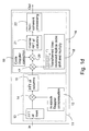
- Fig. 1a presents schematically the acquisition process.
- the processing in acquisition block 6 could be performed at intermediate frequency with appropriate implementation of numerically controlled oscillator, but in the following description it is assumed that the processing is performed at baseband.
- the frequency of the numerically controlled oscillator 4 is set such that the receiver receives the demanded frequencies of the frequency range to be examined.
- the examined bandwidth is 12 kHz.
- the received signal is transformed in a RF-block 2 into the intermediate frequency range or into baseband and sampled in an A/Dconverter block 3.
- the sampling rate of the A/D-converter block 3 is such that at least one coherent sample of every chip is taken.
- GPS C/A signal is periodic with the period of 1ms.
- the chip rate is 1,023 chips (1 epoch) in 1 ms wherein the sampling rate in acquisition stage is preferably 1024 samples in 1 ms, or an integer multiple of it.
- sample vector x n The 1024 samples of the sample vector represent a signal having ca. 1 ms length. The sampling of the signal continues wherein the next 1024 samples are stored as the next sample vector x n .
- sample vectors are continuous in time such that the following sample vector continues after the previous sample vector, i.e. the time difference between the last sample of the previous sample vector and the first sample of the next sample vector is substantially the same as the time difference between samples in the sample vectors.
- sampling method 1023 samples (or multiple of 1023) are taken and then one (or multiple) extra values, preferably zeros, are added to the sample vectors to achieve a vector length which is a power of two. This makes the FFT algorithms easier compared with the situation where the length of the sample vectors is other than a power of two.
- a first time-to-frequency transform is performed after the sampling phase in the method according to the invention.
- the first time-to-frequency transform is performed to the samples of the sample vectors such that in each transform one sample of each sample vector is used. For example, the first samples of each sample vector are used in one transform, the second samples of each sample vector are used in another transform, etc. Therefore 1024 time-to-frequency transforms are performed for each fine Doppler search in this advantageous embodiment of the invention.
- the results of these time-to-frequency transforms are saved as a first transform matrix Y.
- This time-to-frequency transform is preferably a fast Fourier transform (FFT) and it is illustrated as a first FFT block 12 in Fig. 1b.
- FFT fast Fourier transform
- the Fourier transform will be primarily used as an example of a time-to-frequency transform and an inverse Fourier transform as an example of an inverse transform, i.e. a frequency-to-time transform; however, it is obvious that the present invention is not limited solely to these examples.
- An advantageous embodiment of the invention comprises also an in-epoch compensation phase 13 which is performed after the first time-to-frequency transform phase to eliminate possible degradation of correlation peak values due to the Doppler shift.
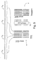
- This degradation is illustrated in Fig. 4.
- a curve A illustrates the non-compensated correlation result in frequency domain.
- a curve B illustrates the compensated correlation result and a curve C illustrates the normalized compensated correlation result when a windowing is used with FFT, respectively. From Fig. 4 it can clearly be seen how the in-epoch compensation increases the accuracy of the correlation phase. This is achieved by multiplying 14 the values of the matrix Y with respective values of a compensation matrix C (Fig. 6). The result of the point-by-point multiplication is illustrated as a compensated matrix CY in Fig. 6.
- each column of the matrix Y or CY is the Doppler compensated and coherently combined epochs of original signal assuming a particular fine Doppler frequency.
- the correlation phase is to be performed for each column of matrix Y or CY in which the correlation between the received signal of a satellite and the locally generated pseudo random code r of the satellite is calculated.
- the correlation phase is illustrated as a simplified diagram in Fig. 7a.
- the correlation result gives information of the code phase of the received signal.
- the correlation could be performed using methods of prior art but in the preferred embodiment of the invention it is performed in frequency domain.
- the correlation in time domain corresponds to a multiplication in frequency domain. Therefore, the matrix Y, or the compensated matrix CY, is transformed 16 to frequency domain.
- the transform is performed in orthogonal direction with respect to the first time-to-frequency transform which in this advantageous embodiment of the invention means that the transform is performed by columns (epoch-by-epoch).
- the pseudo random codes r of each satellite of the positioning system are preferably stored in the receiver, or the codes are generated in the receiver when needed.
- the receiver selects, i.e. retrieves from the memory or generates the pseudo random code r which corresponds to the modulating code of the signal of the satellite into which the receiver is trying to perform the acquisition.
- This pseudo random code is called a replica code later in this description as a distinction to the actual pseudo random code used in the transmitting satellite.
- a time reversal is performed to the period of the replica code r.
- the time reversal means such a modification that the first chip of the replica code becomes the last chip, the second chip becomes the second last chip, etc.
- the time reversed replica code is then transformed preferably to frequency domain by using e.g. fast Fourier transform.
- the time reversed version of the replica code can be stored into memory instead of the actual replica code r, or the receiver can directly generate the time reversed version of the replica code, wherein the time reversal of the replica code is not necessary during the operation of the receiver.
- the transform domain version R of the reversed replica code can be stored in the receiver instead of the reversed replica code and the time-to-frequency transform of the reversed replica code is not needed during the acquisition phase.
- the matrix Y, or the compensated matrix CY, is directed as a first input into a correlator block 35 and the frequency domain version R of the reversed replica code is directed as a second input into the multiplier block 17. Then these two frequency domain inputs are multiplied and the result of the multiplication is transformed by columns into time domain in the frequency-to-time transform block 21. It should be noted here that the matrices Y, CY, Z i are shown transposed in Fig. 7a, 8 for visualization purposes. The time domain output of the correlator block is then saved as a first correlation matrix Z 1 (Fig. 8) for further inspection.
- Each column of the first correlation matrix Z 1 comprises the crosscorrelation of the replica code r with all possible circular shifts of the same row of matrix Y, or CY.
- the next correlation matrix Z 2 is formed in the similar way, it is added non-coherently to the first one and the process continues for several consecutive matrices.
- Figure 8 illustrates the non-coherent addition of the correlation matrices Z 1 ⁇ Z w to form a search matrix S. It is evident, that the addition could be performed on-line without accumulating all the matrices.
- the non-coherent addition can be performed e.g. such that the absolute values of the elements of each correlation matrix Z are calculated and added up.
- the code phase and Doppler shift can now be searched by analyzing the search matrix S. In the analysis the values of the elements of the search matrix S are evaluated and advantageously a maximum value is searched. Then the maximum value is found and if it exceeds the decision threshold the matrix indexes (row, column) of the maximum value define the correct code phase and Doppler shift which then can be used during the tracking and position calculation phases known as such.
- This non-coherent processing is illustrated as a block 22 in Fig. 1b. If the maximum value does not exceed the decision threshold then it is decided that a signal is not present at this set of frequencies and the acquisition process continues with next coarse search stage. It is obvious that the above described method for detecting a signal of a satellite is used as an example here but other types of detectors could be used for signal detection as well.
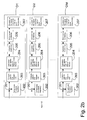
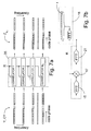
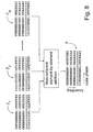
- Fig. 2 The above described two-phase analyzing procedure is also illustrated in Fig. 2 where the lines on the left illustrate the frequency range division for the coarse Doppler search and the lines on the right illustrate the frequency range division for the fine Doppler search.
- the sequence of received GPS data is denoted as x and n in a situation that the Doppler shift is not affecting to the signal.
- the number of samples in epoch is denoted as N 2 and the number of periods during coherent processing is denoted as N 1 .
- N 1 the number of samples in epoch
- N 1 the number of periods during coherent processing
- n 1 which indicates the epoch
- n 2 which indicate the position within the epoch.
- Fig. 3 The Doppler shift introduced by the satellite motion and local clock inaccuracies is defined as k/(N 1 N 2 ), i.e. taking the discrete grid of frequencies. Due to this Doppler shift the input signal is effected by a modulation and an additive noise x noise in a form
- the multiplier e j ⁇ is neglected as it is a common scaling factor which it is not relevant for the further analysis and it cancels out during the non-coherent processing.
- GPS receiver multiplies the incoming signal with a local replica code and integrates over several periods of the GPS signal with overall number of samples involved N 1 N 2 .
- the coherent addition of epochs as the method to increase the signal-to-noise ratio will cause correlation peaks to be degraded if not compensated appropriately before the correlation as was mentioned earlier in the description.
- the compensation can be performed by multiplying the incoming sequence by e - j 2 ⁇ N 1 N 2 kn
- Fig.2b in which the method is illustrated as a simplified diagram.
- the input signal is examined in coarse frequency steps.
- the blocks D1, D2, ..., DM illustrate those coarse frequency steps.
- the coarse compensation is performed for each selected frequency step by mixing 201 the input signal with the signal of the numerically controlled oscillator 4.
- the frequency of the numerically controlled oscillator 4 is tuned 202 e.g. in 1 kHz steps for each examining phase.
- the compensation for fine frequencies is performed 203 prior the correlation with replica code for different code phases 204.
- the correlation results are combined coherently 205 and non-coherently 206 to produce a search matrix S.
- the search matrix X is examined 207 e.g. by comparing it with a preset threshold value. If the decision signal has at least one value which is greater than the threshold value, it can be assumed that there exists a signal of a satellite at the examined frequency range. Also other prior art detection methods can be used to decide if there exists a signal of a satellite at the examined frequency range.
- a variable z is defined such that the components r n 2 of replica vector r are involved:
- F is the time-to-frequency matrix
- the elements of the matrix Y should be point-by-point multiplied with an appropriate complex sinusoid value.
- the formula means that the incoming signal x n would be multiplied with a sinusoid defined by coarse frequency variable k 2 prior to the time-to-frequency transform. This could be done before fine Doppler compensation as it is shown in Fig. 1a, Fig. 1b and Fig. 2b but it could also be performed in a way presented in Figs. 1c and 1d without using of numerically controlled oscillator 4 for acquisition process.
- the meaning of the cross-correlation is to find the match in code phase between the received data and the replica code.
- the replica shifting approach is considered in detail later in this description.
- the equation (7) shows that the coarse acquisition modulation is independent on both the fine frequency k 1 and particular epoch n 1 . This means that the same modulation applies to all the epochs and it can be taken out of the time-to-frequency transform of the rows of the matrix X. In the following matrixes are used to further explain the cross-correlation.
- the outer sum in the equation (3) is to be considered. In fact, this means actually that the replica code is correlated with the coherently enhanced incoming signal. This sum should be performed for all possible circular replica code shifts because the code phase of the incoming signal is unknown.
- DFT discrete Fourier transform
- FFT fast implementation
- the cross-correlation method using DFT assumes that DFT of received signal fragment is point-by-point multiplied by the DFT of the time-reversed replica code and the inverse DFT shows the result of the cross-correlation.
- the above equation (8) can be modified by point-by-point multiplication of two matrices C and ⁇ F T .
- This point-by-point multiplication of two matrices is denoted as (.*) in this description.
- the specified range of k 1 is due to the fact that the range of frequencies less than 1 kHz are to be considered at this stage.
- the equation (9) can be modified into a form where M 1 is a diagonal matrix and So each column is modulated arid then time-to-frequency transform such as FFT is performed.
- N 2 is the epoch length and the properties of the DFT, modulation on the input by e - j 2 ⁇ N 2 k 2 n 2 .
- modulation on the input by e - j 2 ⁇ N 2 k 2 n 2 circularly shifts the output of the time-to-frequency transform by k 2 , i.e. by an integer shift.
- the transform domain representation of the time-reversed replica code is circularly shifted, the result is a shifted vector prior to frequency-to-time transform, such as inverse FFT.
- Shifting in the transform domain can be considered as modulation in time domain. Therefore the coarse modulation on the input of the correlator exhibits itself as a modulation on its output if the transform domain representation of the time-reversed replica code is circularly shifted by k 2 . More formally, the cross-correlation can be written as where R shift is the diagonal matrix with diagonal elements representing transform domain replica code shifted circularly by k 2 positions. The complex exponentials in M 1 are constant for each row and normally they are not significant for non-coherent processing and detection. If necessary, they can be compensated by appropriate multiplication. As a conclusion from the mathematical inspection above is that the modulation in the input (right of F in equation 9) is moved to the output (left of F in the equation 11).
- Fig.1d shows the structure of the acquisition block with the method of shifting the replica code.
- the numerically controlled oscillator 4 is not required for acquisition in this advantageous embodiment of the invention but it is used for tracking purposes.
- Another remarkable advantage of using the method of shifting the replica code is the possibility of significantly reducing the computation complexity at the expense of memory.
- the input signal is time-to-frequency transformed twice, in-epoch compensated, and stored into memory. This part is performed by the section 11 in Fig.1d. Then the result can be used for all coarse frequency stages and with all the replica codes. This will be performed by block 16 in Fig.1d.
- the complexity then is reduced almost two times and is mainly due to inverse DFT (FFT).
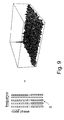
- Figure 10 illustrates an example of the two-dimensional search matrix S formed by the shifting of the FFT transformed pseudo random replica sequence of the corresponding satellite according to an advantageous embodiment of the invention.
- the receiver performs the reception of a signal preferably on the basis of the signal received from at least four satellites.
- the above presented steps are repeated for the signal of each satellite, if necessary.
- a majority of the blocks required for applying the method can be implemented e.g. in a digital signal processor (not shown).
- a digital signal processor (not shown).
- To perform the FFT transforms it is possible to use either hardware-based solutions or software applications in the digital signal processor.
- a control means preferably a microprocessor or the like, which is, however, not presented in the appended drawings, and which is prior art known to anyone skilled in the art.
- At least some of the blocks required for applying the method can also be implemented in a communication network (not shown), wherefore such blocks are not necessarily needed in the receiver.
- the receiver and the network are arranged to communicate with each other so that the steps according to the invention can be performed.
- the circular shifting of the replica code is also applicable in other FFT based correlation systems, where a phase shift of a received, code-phase modulated signal is to be determined, e.g. CDMA systems (code division-multiple access).
- CDMA systems code division-multiple access
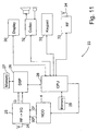
- the appended Fig. 11 shows an electronic device 23 complying with an advantageous embodiment of the invention, comprising functions of a wireless communication device and a positioning receiver.
- a first antenna 24 is used to receive a signal transmitted from positioning satellites.
- the received signal is transferred to a first radio part 25, in which the signal is converted to an intermediate frequency and digitized.
- the first radio part comprises e.g. a downconverter block 2, and an A/D-converter block 3 and a multiplier block 36 in the receiver 1 of Fig. 1a or Fig. 1c.
- the digitized signal which at this stage preferably comprises I and Q components, is transferred to a digital signal processing unit 26, in which e.g.
- the electronic device 23 also comprises first memory means 27 which comprise e.g. a random access memory for storing data required during the operation of the receiver, as well as preferably also a read only memory and/or an non-volatile random access memory for storing the program code of the digital signal processing unit 26.
- first memory means 27 comprise e.g. a random access memory for storing data required during the operation of the receiver, as well as preferably also a read only memory and/or an non-volatile random access memory for storing the program code of the digital signal processing unit 26.
- the control block 7 such as the FFT transform blocks 12, 15, the multipliers 14, 17, 20 and the inverse FFT block 21 are implemented in the signal processing unit 26.
- the digital signal processing unit 26 comprises preferably also means for generating and shifting the frequency domain replica code. It is obvious that at least some of said functional blocks can also be implemented in another way known per se.
- the FFT transform blocks 12, 15 and the inverse FFT transform block 21 can also be implemented with integrated circuits, or the like, designed for
- the digital signal processing unit 26 transfers the values for determining the code phase and the frequency deviation to be used in the determining block 22 to a processor block 28 which comprises e.g. a microprocessor and I/O logics. Some of the functions of the acquisition block 6 are preferably at least partly implemented as program commands in the processor block.
- a processor block 28 which comprises e.g. a microprocessor and I/O logics. Some of the functions of the acquisition block 6 are preferably at least partly implemented as program commands in the processor block.
- second memory means 29 are used as the data memory and the program memory for the processor block 28. It is obvious that the first memory means 27 and the second memory means 29 can also comprise a common memory. Positioning information can be displayed to the user on a display 30.
- the wireless communication device functions of the wireless communication device are implemented in the application software of the processor block 28.
- the display 30 can also be used, in a way known per se, to display e.g. call information.
- the user can control the positioning receiver as well as the wireless communication device.
- a codec 32 is used to encode and decode audio signals.
- Fig. 11 shows a radio part 33 and a second antenna 34 for the wireless communication device.
Landscapes
- Engineering & Computer Science (AREA)
- Computer Networks & Wireless Communication (AREA)
- Radar, Positioning & Navigation (AREA)
- Remote Sensing (AREA)
- Signal Processing (AREA)
- Physics & Mathematics (AREA)
- General Physics & Mathematics (AREA)
- Position Fixing By Use Of Radio Waves (AREA)
Applications Claiming Priority (2)
| Application Number | Priority Date | Filing Date | Title |
|---|---|---|---|
| FI20000819 | 2000-04-06 | ||
| FI20000819A FI20000819A (fi) | 2000-04-06 | 2000-04-06 | Menetelmä vastaanottimessa ja vastaanotin |
Publications (2)
| Publication Number | Publication Date |
|---|---|
| EP1143674A2 true EP1143674A2 (de) | 2001-10-10 |
| EP1143674A3 EP1143674A3 (de) | 2004-01-21 |
Family
ID=8558140
Family Applications (1)
| Application Number | Title | Priority Date | Filing Date |
|---|---|---|---|
| EP01660058A Withdrawn EP1143674A3 (de) | 2000-04-06 | 2001-03-28 | Frequenzversatzuntersuchung in einem CDMA-Empfänger |
Country Status (3)
| Country | Link |
|---|---|
| US (1) | US6909738B2 (de) |
| EP (1) | EP1143674A3 (de) |
| FI (1) | FI20000819A (de) |
Cited By (9)
| Publication number | Priority date | Publication date | Assignee | Title |
|---|---|---|---|---|
| WO2003047121A1 (en) * | 2001-11-26 | 2003-06-05 | Ubinetics Limited | Method and apparatus for determining the frequency error of an oscillator in a cdma receiver |
| EP1319189A2 (de) * | 2000-09-18 | 2003-06-18 | Cellguide Ltd. | Effizienter algorithmus zur verarbeitung von gps-signalen |
| WO2004034604A1 (en) * | 2002-10-11 | 2004-04-22 | The Mitre Corporation | System for direct acquisition of received signals |
| WO2004070413A2 (en) * | 2003-01-31 | 2004-08-19 | Sirf Technology Inc. | Reducing memory usage in noncoherent signal processing |
| US6985542B1 (en) | 2000-06-02 | 2006-01-10 | Cellguide Ltd. | Coherent processing of satellite signals to locate a mobile unit |
| US7064708B2 (en) | 2002-10-24 | 2006-06-20 | Nokia Corporation | Validation of beacon signals |
| US7327311B2 (en) * | 2001-02-06 | 2008-02-05 | Nxp B.V. | Method of despreading GPS signals |
| CN103166893A (zh) * | 2011-12-14 | 2013-06-19 | 联芯科技有限公司 | Lte系统最大时延扩展估计的实现方法和装置 |
| EP2811320A1 (de) * | 2013-06-05 | 2014-12-10 | Astrium Limited | Empfänger und Verfahren für Direktsequenz-Spreizspektrum-Signale |
Families Citing this family (34)
| Publication number | Priority date | Publication date | Assignee | Title |
|---|---|---|---|---|
| US6720917B2 (en) * | 2000-12-04 | 2004-04-13 | The United States Of America As Represented By The Secretary Of The Air Force | Acquisition for GPS C/A code and P(Y) code |
| JP3676991B2 (ja) * | 2001-07-05 | 2005-07-27 | 松下電器産業株式会社 | 無線通信装置及び無線通信方法 |
| US7596190B2 (en) * | 2002-04-01 | 2009-09-29 | Qualcomm Incorporated | System, method, and apparatus for correction of code doppler shift |
| WO2004038944A1 (en) | 2002-10-24 | 2004-05-06 | Nokia Corporation | Determination of the correlation phase between a signal and a replica sequence |
| US8098765B1 (en) * | 2004-02-23 | 2012-01-17 | Sirf Technology, Inc. | Reducing and sharing computations for GPS signal processing |
| US7486749B2 (en) * | 2004-12-22 | 2009-02-03 | Nokia Corporation | Determination of a code phase |
| US20080191932A1 (en) * | 2005-03-31 | 2008-08-14 | Erwin Hemming | Method and Device for Correlation Detection in Spread Spectrum Transmission Systems by Fast Fourier Transformation |
| US8275397B2 (en) | 2005-07-14 | 2012-09-25 | Huston Charles D | GPS based friend location and identification system and method |
| US8207843B2 (en) | 2005-07-14 | 2012-06-26 | Huston Charles D | GPS-based location and messaging system and method |
| US11972450B2 (en) | 2005-07-14 | 2024-04-30 | Charles D. Huston | Spectator and participant system and method for displaying different views of an event |
| US8933967B2 (en) | 2005-07-14 | 2015-01-13 | Charles D. Huston | System and method for creating and sharing an event using a social network |
| US9445225B2 (en) * | 2005-07-14 | 2016-09-13 | Huston Family Trust | GPS based spectator and participant sport system and method |
| US9344842B2 (en) | 2005-07-14 | 2016-05-17 | Charles D. Huston | System and method for viewing golf using virtual reality |
| WO2007011648A2 (en) * | 2005-07-14 | 2007-01-25 | Huston Charles D | Gps based spectator and participant sport system and method |
| US8249626B2 (en) * | 2005-07-14 | 2012-08-21 | Huston Charles D | GPS based friend location and identification system and method |
| US7471238B2 (en) * | 2005-11-01 | 2008-12-30 | The Aerospace Corporation | Multitarget tracking antispoofing receiver |
| DE602006001358D1 (de) * | 2006-02-20 | 2008-07-10 | Alcatel Lucent | Kompensationsregelung des Dopplereffektes zur Funkübertragung |
| TWI341672B (en) * | 2006-03-08 | 2011-05-01 | Lite On Technology Corp | Method and receiver capable of increasing acquisition efficiency in a code division multiple access communication system |
| EP2067327B1 (de) * | 2006-09-11 | 2015-04-15 | Telefonaktiebolaget LM Ericsson (publ) | Detektion von Zeit-Frequenz-Sprungmustern |
| US8295328B2 (en) * | 2006-10-11 | 2012-10-23 | Telefonaktiebolaget Lm Ericsson (Publ) | Doppler frequency control of G-rake receiver |
| US8295325B2 (en) * | 2007-01-12 | 2012-10-23 | Telefonaktiebolaget L M Ericsson (Publ) | Signature sequences and methods for time-frequency selective channel |
| US8300674B2 (en) * | 2007-01-12 | 2012-10-30 | Telefonaktiebolaget L M Ericsson (Publ) | Method and apparatus for complexity reduction in detection of delay and Doppler shifted signature sequences |
| US8009086B2 (en) * | 2008-02-13 | 2011-08-30 | The United States Of America As Represented By The Secretary Of The Navy | System and method for geo-locating a receiver with reduced power consumption |
| US8811331B2 (en) * | 2008-04-10 | 2014-08-19 | Telefonaktiebolaget L M Ericsson (Publ) | Pilot design using costas arrays |
| US8442095B2 (en) * | 2008-06-14 | 2013-05-14 | Qualcomm Incorporated | Multiple correlation processing in code space search |
| US20100093301A1 (en) * | 2008-10-14 | 2010-04-15 | Electronics And Telecommunications Research Institute | Heterodyne receiver using analog discrete-time signal processing and signal receiving method thereof |
| US8446931B1 (en) * | 2011-04-19 | 2013-05-21 | L-3 Communications Corp | Chip timing synchronization for link that transitions between clear and spread modes |
| FI122637B (fi) * | 2011-04-28 | 2012-04-30 | Fastrax Ltd | Signaalinkäsittelymenetelmä, -laite ja -järjestelmä |
| KR101564828B1 (ko) * | 2014-01-20 | 2015-10-30 | 한국과학기술원 | 도플러 주파수가 있는 미약한 대역확산 신호의 초고속 신호 획득 및 추적을 위한 신호 처리 방법 및 그 장치 |
| WO2018014980A1 (en) * | 2016-07-22 | 2018-01-25 | U-Blox Ag | Global navigation satellite system (gnss) signal tracking |
| US11686855B2 (en) * | 2019-10-15 | 2023-06-27 | Onenav, Inc. | Modernized global navigation satellite system (GNSS) receivers and commercially viable consumer grade GNSS receivers |
| US11821993B2 (en) * | 2020-06-01 | 2023-11-21 | Onenav, Inc. | Modernized consumer grade GNSS secondary code acquisition and signal tracking |
| US11874382B2 (en) * | 2021-02-11 | 2024-01-16 | Mitre Corporation | GNSS spoofing detection using peak suppression monitor |
| CN113422658B (zh) * | 2021-06-17 | 2023-02-03 | 中国电子科技集团公司第二十九研究所 | 一种通道间采样时序不同步的校正方法及系统 |
Family Cites Families (8)
| Publication number | Priority date | Publication date | Assignee | Title |
|---|---|---|---|---|
| US5192957A (en) * | 1991-07-01 | 1993-03-09 | Motorola, Inc. | Sequencer for a shared channel global positioning system receiver |
| US5402347A (en) | 1993-07-22 | 1995-03-28 | Trimble Navigation Limited | Satellite search methods for improving time to first fix in a GPS receiver |
| US6028883A (en) * | 1996-07-12 | 2000-02-22 | General Electric Company | Low power signal processing for spread spectrum receivers |
| US6151353A (en) * | 1996-07-12 | 2000-11-21 | General Electric Company | Pre-acquisition frequency offset removal in a GPS receiver |
| US6289041B1 (en) * | 1997-02-11 | 2001-09-11 | Snaptrack, Inc. | Fast Acquisition, high sensitivity GPS receiver |
| US6005889A (en) * | 1997-07-17 | 1999-12-21 | Nokia | Pseudo-random noise detector for signals having a carrier frequency offset |
| FI19992653A (fi) * | 1999-12-09 | 2001-06-10 | Nokia Mobile Phones Ltd | Menetelmä vastaanottimen tahdistamiseksi ja vastaanotin |
| US6810072B1 (en) * | 2000-05-30 | 2004-10-26 | Nokia Corporation | System for acquiring spread spectrum signals |
-
2000
- 2000-04-06 FI FI20000819A patent/FI20000819A/fi unknown
-
2001
- 2001-03-28 EP EP01660058A patent/EP1143674A3/de not_active Withdrawn
- 2001-04-04 US US09/826,260 patent/US6909738B2/en not_active Expired - Lifetime
Non-Patent Citations (1)
| Title |
|---|
| None * |
Cited By (16)
| Publication number | Priority date | Publication date | Assignee | Title |
|---|---|---|---|---|
| US6985542B1 (en) | 2000-06-02 | 2006-01-10 | Cellguide Ltd. | Coherent processing of satellite signals to locate a mobile unit |
| EP1319189A4 (de) * | 2000-09-18 | 2008-08-20 | Cellguide Ltd | Effizienter algorithmus zur verarbeitung von gps-signalen |
| EP1319189A2 (de) * | 2000-09-18 | 2003-06-18 | Cellguide Ltd. | Effizienter algorithmus zur verarbeitung von gps-signalen |
| US7327311B2 (en) * | 2001-02-06 | 2008-02-05 | Nxp B.V. | Method of despreading GPS signals |
| WO2003047121A1 (en) * | 2001-11-26 | 2003-06-05 | Ubinetics Limited | Method and apparatus for determining the frequency error of an oscillator in a cdma receiver |
| WO2004034604A1 (en) * | 2002-10-11 | 2004-04-22 | The Mitre Corporation | System for direct acquisition of received signals |
| US7447259B2 (en) | 2002-10-11 | 2008-11-04 | The Mitre Corporation | System for direct acquisition of received signals |
| KR100809118B1 (ko) * | 2002-10-11 | 2008-03-03 | 더 마이터 코포레이션 | 수신 신호의 직접 획득 시스템 |
| US7064708B2 (en) | 2002-10-24 | 2006-06-20 | Nokia Corporation | Validation of beacon signals |
| WO2004070413A3 (en) * | 2003-01-31 | 2004-11-11 | Sirf Tech Inc | Reducing memory usage in noncoherent signal processing |
| WO2004070413A2 (en) * | 2003-01-31 | 2004-08-19 | Sirf Technology Inc. | Reducing memory usage in noncoherent signal processing |
| CN103166893A (zh) * | 2011-12-14 | 2013-06-19 | 联芯科技有限公司 | Lte系统最大时延扩展估计的实现方法和装置 |
| CN103166893B (zh) * | 2011-12-14 | 2015-12-09 | 联芯科技有限公司 | Lte系统最大时延扩展估计的实现方法和装置 |
| EP2811320A1 (de) * | 2013-06-05 | 2014-12-10 | Astrium Limited | Empfänger und Verfahren für Direktsequenz-Spreizspektrum-Signale |
| WO2014195712A1 (en) * | 2013-06-05 | 2014-12-11 | Airbus Defence And Space Limited | Receiver and method for direct sequence spread spectrum signals |
| US10281584B2 (en) | 2013-06-05 | 2019-05-07 | Airbus Defence And Space Limited | Receiver and method for direct sequence spread spectrum signals |
Also Published As
| Publication number | Publication date |
|---|---|
| EP1143674A3 (de) | 2004-01-21 |
| US6909738B2 (en) | 2005-06-21 |
| US20010033606A1 (en) | 2001-10-25 |
| FI20000819A (fi) | 2002-01-25 |
| FI20000819A0 (fi) | 2000-04-06 |
Similar Documents
| Publication | Publication Date | Title |
|---|---|---|
| US6909738B2 (en) | Method in a receiver and a receiver | |
| US7224721B2 (en) | System for direct acquisition of received signals | |
| US7042930B2 (en) | Spread spectrum bit boundary correlation search acquisition system | |
| US7876811B2 (en) | Method and apparatus for detecting spreading-code synchronization for spectrum spreading signals | |
| US7257153B2 (en) | Method of synchronizing a receiver, and a receiver | |
| US6792035B2 (en) | Method and apparatus for reducing the effect of multipath propagation in a received signal | |
| KR100810481B1 (ko) | 정합 필터를 사용하여 gps 를 프로세싱하는 방법 및 장치 | |
| US9252826B2 (en) | Method and apparatus for reducing the time required to acquire a GPS signal | |
| EP1430616B1 (de) | Verfahren und vorrichtung zur durchführung einer signalkorrelation unter verwendung vorgeschichtlicher korrelationsdaten | |
| WO2005040845A1 (en) | Method and appartus for performing signal correlation using historical correlation data | |
| EP1749349A1 (de) | Durchführung einer beschaffung in einem empfänger | |
| EP1379010B1 (de) | Verfahren, System und elektronisches Gerät zur Synchronisation eines Empfängers | |
| US7151793B2 (en) | Method for synchronizing a receiver, a positioning system, a receiver and an electronic device | |
| WO2000065751A1 (en) | Apparatus for computing gps correlations in parallel | |
| US7308021B2 (en) | Method in the synchronization of a receiver, and a receiver | |
| Akopian et al. | Fast DS-SS Acquisition Implementation for High Sensitivity Receivers |
Legal Events
| Date | Code | Title | Description |
|---|---|---|---|
| PUAI | Public reference made under article 153(3) epc to a published international application that has entered the european phase |
Free format text: ORIGINAL CODE: 0009012 |
|
| AK | Designated contracting states |
Kind code of ref document: A2 Designated state(s): AT BE CH CY DE DK ES FI FR GB GR IE IT LI LU MC NL PT SE TR |
|
| AX | Request for extension of the european patent |
Free format text: AL;LT;LV;MK;RO;SI |
|
| RAP1 | Party data changed (applicant data changed or rights of an application transferred) |
Owner name: NOKIA CORPORATION |
|
| PUAL | Search report despatched |
Free format text: ORIGINAL CODE: 0009013 |
|
| AK | Designated contracting states |
Kind code of ref document: A3 Designated state(s): AT BE CH CY DE DK ES FI FR GB GR IE IT LI LU MC NL PT SE TR |
|
| AX | Request for extension of the european patent |
Extension state: AL LT LV MK RO SI |
|
| 17P | Request for examination filed |
Effective date: 20040601 |
|
| AKX | Designation fees paid |
Designated state(s): DE FR GB NL |
|
| 17Q | First examination report despatched |
Effective date: 20070221 |
|
| STAA | Information on the status of an ep patent application or granted ep patent |
Free format text: STATUS: THE APPLICATION IS DEEMED TO BE WITHDRAWN |
|
| 18D | Application deemed to be withdrawn |
Effective date: 20070704 |