EP3255281A1 - Ventilateur avec aubes de diffuseur tandem - Google Patents
Ventilateur avec aubes de diffuseur tandem Download PDFInfo
- Publication number
- EP3255281A1 EP3255281A1 EP17000947.6A EP17000947A EP3255281A1 EP 3255281 A1 EP3255281 A1 EP 3255281A1 EP 17000947 A EP17000947 A EP 17000947A EP 3255281 A1 EP3255281 A1 EP 3255281A1
- Authority
- EP
- European Patent Office
- Prior art keywords
- fan unit
- nachleitschaufeln
- unit according
- nachleitapparat
- guide vanes
- Prior art date
- Legal status (The legal status is an assumption and is not a legal conclusion. Google has not performed a legal analysis and makes no representation as to the accuracy of the status listed.)
- Granted
Links
- 230000001681 protective effect Effects 0.000 claims description 68
- 239000002184 metal Substances 0.000 claims description 8
- 238000001746 injection moulding Methods 0.000 description 5
- 238000004519 manufacturing process Methods 0.000 description 5
- 239000000969 carrier Substances 0.000 description 4
- 238000009826 distribution Methods 0.000 description 3
- 238000003698 laser cutting Methods 0.000 description 2
- 238000004080 punching Methods 0.000 description 2
- 230000035939 shock Effects 0.000 description 2
- 230000033228 biological regulation Effects 0.000 description 1
- 230000015572 biosynthetic process Effects 0.000 description 1
- 238000005520 cutting process Methods 0.000 description 1
- 230000007423 decrease Effects 0.000 description 1
- 238000010586 diagram Methods 0.000 description 1
- 238000002347 injection Methods 0.000 description 1
- 239000007924 injection Substances 0.000 description 1
- 244000144972 livestock Species 0.000 description 1
- 239000007769 metal material Substances 0.000 description 1
- 238000000034 method Methods 0.000 description 1
- 238000012805 post-processing Methods 0.000 description 1
- 230000000087 stabilizing effect Effects 0.000 description 1
- 230000007704 transition Effects 0.000 description 1
Images


Classifications
-
- F—MECHANICAL ENGINEERING; LIGHTING; HEATING; WEAPONS; BLASTING
- F04—POSITIVE - DISPLACEMENT MACHINES FOR LIQUIDS; PUMPS FOR LIQUIDS OR ELASTIC FLUIDS
- F04D—NON-POSITIVE-DISPLACEMENT PUMPS
- F04D25/00—Pumping installations or systems
- F04D25/02—Units comprising pumps and their driving means
- F04D25/08—Units comprising pumps and their driving means the working fluid being air, e.g. for ventilation
-
- F—MECHANICAL ENGINEERING; LIGHTING; HEATING; WEAPONS; BLASTING
- F24—HEATING; RANGES; VENTILATING
- F24F—AIR-CONDITIONING; AIR-HUMIDIFICATION; VENTILATION; USE OF AIR CURRENTS FOR SCREENING
- F24F13/00—Details common to, or for air-conditioning, air-humidification, ventilation or use of air currents for screening
- F24F13/08—Air-flow control members, e.g. louvres, grilles, flaps or guide plates
-
- F—MECHANICAL ENGINEERING; LIGHTING; HEATING; WEAPONS; BLASTING
- F04—POSITIVE - DISPLACEMENT MACHINES FOR LIQUIDS; PUMPS FOR LIQUIDS OR ELASTIC FLUIDS
- F04D—NON-POSITIVE-DISPLACEMENT PUMPS
- F04D29/00—Details, component parts, or accessories
- F04D29/40—Casings; Connections of working fluid
- F04D29/52—Casings; Connections of working fluid for axial pumps
- F04D29/54—Fluid-guiding means, e.g. diffusers
- F04D29/541—Specially adapted for elastic fluid pumps
- F04D29/542—Bladed diffusers
-
- A—HUMAN NECESSITIES
- A01—AGRICULTURE; FORESTRY; ANIMAL HUSBANDRY; HUNTING; TRAPPING; FISHING
- A01K—ANIMAL HUSBANDRY; AVICULTURE; APICULTURE; PISCICULTURE; FISHING; REARING OR BREEDING ANIMALS, NOT OTHERWISE PROVIDED FOR; NEW BREEDS OF ANIMALS
- A01K1/00—Housing animals; Equipment therefor
- A01K1/0047—Air-conditioning, e.g. ventilation, of animal housings
- A01K1/0052—Arrangement of fans or blowers
-
- A—HUMAN NECESSITIES
- A01—AGRICULTURE; FORESTRY; ANIMAL HUSBANDRY; HUNTING; TRAPPING; FISHING
- A01K—ANIMAL HUSBANDRY; AVICULTURE; APICULTURE; PISCICULTURE; FISHING; REARING OR BREEDING ANIMALS, NOT OTHERWISE PROVIDED FOR; NEW BREEDS OF ANIMALS
- A01K1/00—Housing animals; Equipment therefor
- A01K1/0047—Air-conditioning, e.g. ventilation, of animal housings
- A01K1/0064—Construction of air inlets or outlets in walls
-
- F—MECHANICAL ENGINEERING; LIGHTING; HEATING; WEAPONS; BLASTING
- F04—POSITIVE - DISPLACEMENT MACHINES FOR LIQUIDS; PUMPS FOR LIQUIDS OR ELASTIC FLUIDS
- F04D—NON-POSITIVE-DISPLACEMENT PUMPS
- F04D29/00—Details, component parts, or accessories
- F04D29/40—Casings; Connections of working fluid
- F04D29/52—Casings; Connections of working fluid for axial pumps
- F04D29/54—Fluid-guiding means, e.g. diffusers
- F04D29/541—Specially adapted for elastic fluid pumps
- F04D29/542—Bladed diffusers
- F04D29/544—Blade shapes
-
- F—MECHANICAL ENGINEERING; LIGHTING; HEATING; WEAPONS; BLASTING
- F04—POSITIVE - DISPLACEMENT MACHINES FOR LIQUIDS; PUMPS FOR LIQUIDS OR ELASTIC FLUIDS
- F04D—NON-POSITIVE-DISPLACEMENT PUMPS
- F04D29/00—Details, component parts, or accessories
- F04D29/70—Suction grids; Strainers; Dust separation; Cleaning
- F04D29/701—Suction grids; Strainers; Dust separation; Cleaning especially adapted for elastic fluid pumps
- F04D29/703—Suction grids; Strainers; Dust separation; Cleaning especially adapted for elastic fluid pumps specially for fans, e.g. fan guards
-
- F—MECHANICAL ENGINEERING; LIGHTING; HEATING; WEAPONS; BLASTING
- F24—HEATING; RANGES; VENTILATING
- F24F—AIR-CONDITIONING; AIR-HUMIDIFICATION; VENTILATION; USE OF AIR CURRENTS FOR SCREENING
- F24F13/00—Details common to, or for air-conditioning, air-humidification, ventilation or use of air currents for screening
- F24F13/20—Casings or covers
Definitions
- the invention relates to a fan unit according to the preamble of claim 1.
- the Nachleitrad is mounted in the flow direction behind a shock protection ( EP 1 367 262 B1 ).
- the safety distance between the contact protection and the fan is low in such fan units.
- the ring spacing of the contact protection according to DIN EN ISO 13857 must be correspondingly small. Due to the small ring spacings, however, the efficiency of the fan unit decreases compared to a fan unit with a contact protection with a large ring spacing. The small ring distance is opposed to increasing the throwing distance.
- the invention has for its object to form the generic fan unit so that the throwing distance of the fan unit can be significantly increased with simple design measures.
- two Nachleitapparate are provided, wherein the further Nachleitapparat is assigned to the housed in the fan housing Nachleitapparat.
- the further Nachleitapparat can significantly increase the throwing distance of the fan unit according to the invention. With the additional Nachleitapparat the requirements, which the Ecodesign-guideline, can be met without any problems.
- the further Nachleitapparat further Nachleitschaufeln with which, depending on the shape and / or arrangement, the throwing distance of the fan unit can be easily adapted to the desired application.
- the further Nachleitapparat is part of a protective grid, with which the contact protection is achieved on the fan unit. Since the further Nachleitapparat is part of the protective grid, the further Nachleitapparat can be brought in a simple manner together with the attachment of the protective grid on the fan unit in its installed position. With the protective grid, it is possible to retrofit existing fan units with the other Nachleitapparat. This makes it very easy for the user to retrofit existing fan units in such a way that the required high throw distances are achieved with them.
- the further guide vanes are arranged substantially upright. Then the other guide vanes are in the flow direction, whereby the Air flow is substantially aligned axially. This contributes to a high throw.
- the other guide vanes can be arranged not only vertically but also inclined.
- the other Nachleitschaufeln can consist of sheet metal parts in a simple manner. Then the guide vanes can be very easily and inexpensively produced from sheets, for example, by punching or by laser cutting and the like.
- a very simple and cost-effective training results when the further guide vanes are flat. Then, for example, separated from a sheet guide vanes can be used without further post-processing or post-deformation directly for use as guide vanes.
- the airflow facing the front edge of the further guide vanes is straight.
- a simple attachment of the further guide vanes results when they are arranged at least over part of their length on at least one rod-shaped carrier. However, you can also partially replace the rod-shaped carrier.
- the rod-shaped carrier is attached to the protective grid in such a way that it connects together coaxial rings of the protective grid.
- the rod-shaped carrier thus serves not only for holding and securing the further guide vanes, but also for stabilizing the protective grid.
- two opposing further guide vanes are formed integrally with each other. This has the advantage that at the same time two additional guide vanes are mounted in the same step during manufacture.
- the opposing further guide vanes are part of a flat bar. It can be made of sheet metal or plastic. If the strip is made of sheet metal, it can simply be produced inexpensively from sheet metal by a stamping or a cutting process, in particular by a laser cutting process.
- the flat bar ensures high stability and easy attachment of the other guide vanes.
- these strips are advantageously connected in half-length crossing each other. This can be achieved, for example, that these strips in half length each have a transverse slot over which the intersecting strips can be positively joined together.
- the number of additional guide vanes can also influence the size of the throw.
- the manufacturer is not only the selection criterion, the shape of the further guide vanes and / or the design of the leading edge as an adjustment criterion available, but also the number of other guide vanes. By appropriate adjustment of these different sizes can be for each fan unit to determine the desired optimum throw and set.
- the strips extend over the entire width or over the entire diameter of the protective grid. Then the strips also contribute to the stability of the protective grid.
- the further Nachleitapparat is formed by individual further Nachleitschaufeln, which are attached to the guide vanes, which are provided in the fan housing.
- the further guide vanes can be plugged, for example, onto these guide vanes already present in the ventilator housing. Any other suitable attachment is possible.
- the further Nachleitapparat is arranged in a housing which is attachable to the fan housing.
- This housing with the further Nachleitapparat thus forms a mounting unit that can be attached to the fan housing as a whole.
- the blade height ratio H h N1max / h N2max is between 0.2 and 2.5, preferably between 0.4 and 2, where h N1max is the maximum height of the guide vanes in the housing and h N2max is the maximum height of the further guide vanes.
- the embodiments described below show fan units, which are characterized in that they have two in the flow direction of the air successively arranged Nachleitapparate. With the provided in the flow direction of the air behind the first Nachleitapparat second Nachleitapparat a very high range is achieved. The two Nachleitapparate ensure that the air is distributed evenly and widely in each room. This high throw of the fan unit is achieved with structurally simple measures in the form of the second Nachleitapparates.
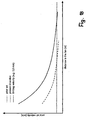
- Fig. 18 shows the dependence of the throw distance on the axial air velocity.
- the dashed line indicates conventional fan units, while the solid line according to the invention fan unit is characterized. It becomes clear that at every axial air speed, the throwing distance is considerably greater than in the case of the known fan units.
- the dotted line indicates the limit speed, which is usually 0.5 m / s, at which the throwing speed is no longer measured, since their values in this range fluctuate too much.
- Fig. 1 shows a protective grid 1, on which a Nachleitapparat 2 is attached.
- the guard 1 has coaxial with each other lying rings 3, which have the same distance from each other in the embodiment. The distance between the rings 3 is chosen so that a reliable contact protection is given.
- the rings 3 are interconnected by struts 4, which are provided at intervals along the circumference of the protective grid 1. In the exemplary embodiment, the struts 4 extend radially and are firmly connected at the intersection points with the rings 3.
- the struts 4 may also be at an angle to the respective radial.
- the struts 4 extend over most of the rings 3. However, the struts 4 can also extend over the entire radial width of the protective grid, so that all the rings 3 are connected to one another by the struts 4.
- the rings 3 and the struts 4 are advantageously made of metallic material, in particular of a wire. In this case, the rings 3 and the struts 4 welded together at their crossing points.
- the rings 3 and the struts 4 may also be made of plastic.
- the Nachleitapparat 2 is attached to one side of the protective grid 1. He has four guide vanes 5, which are each formed the same. They are at angular intervals of 90 ° to each other. They are advantageously made of sheet metal, preferably stamped from a sheet metal strip.
- the guide vanes 5 can also consist of flat plastic parts, which are advantageously produced by injection molding.
- the guide vanes 5 are seated on rod-shaped supports 6, which extend radially and each lie at 90 ° to each other.
- the carriers 6 are located centrally between two adjacent struts 4.
- the carrier 6 are not only used to attach the Nachleitschaufeln 5, but also connect the rings 3 of the protective grid 1 together. In contrast to the struts 4, the carriers 6 extend over all the rings 3.
- the inner ends of the carrier 6 are mounted on a central circular plate 7, which is surrounded at a distance from the innermost ring 3 of the protective grid 1.
- the carrier 6 can be fixed with its inner end over a sufficient length firmly on the circular plate 7.
- the guide vanes 5 have approximately rectangular outline and are provided edgewise on the supports 6.
- the guide vanes 5 are provided on their radially inner narrow side 8 with a recess 9 which extends to the remote from the protective grid 3 longitudinal side 10.
- the radially inner narrow side 8 is at a distance from the central circular plate 7, while the opposite, radially outer narrow side 11 of the Nachleitschaufeln 5 radially outside the outer ring 3 of the protective grid 1 is located.
- the radially inner narrow side 8 is located approximately at the level of the inner ends 12 of the struts 4. This training is not mandatory.
- the arrangement and design of the guide vanes 5 can be designed differently.
- the distribution of the struts 4 and the carrier 6 is provided so that they are provided at equal angular intervals over the circumference of the protective grid 1.
- the Nachleitschaufeln can be provided without the recess 9 on the narrow side 8.
- the carriers 6 protrude radially outwardly beyond the guide vanes 5 and over the outer ring 3 of the protective grid 1 and are designed as fastening elements 13 with which the entire protective grid 1 with Vietnameseleitapparat 2 can be attached to the fan unit.
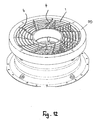
- the Fig. 14 and 15 show this protective grid 1, as it is connected to the fan unit.
- the fan unit has a housing 14 which is formed as an inlet nozzle 15 at one end. It goes into a mounting flange 16, with which the housing 14 and thus the entire fan unit can be mounted on an aggregate or the like in a known manner.
- the inlet nozzle 15 merges into a cylindrical region 17, which connects the inlet nozzle 15 with a diffuser 18, which widens steadily in the flow direction of the air.
- To the diffuser 18 includes an annular mounting flange 19. He has distributed over its circumference recesses 20, in which engage the fasteners 13 of the carrier 6 of the Nachleitapparates 2 ( Fig. 14 ). In the recesses 20, the fasteners 13 are secured in a suitable manner.
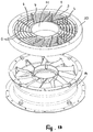
- the protective grid 1 with the Nachleitapparat 2 is mounted on the mounting flange 19, that the Nachleitschaufeln 5 facing the guide vanes 21 of the fan unit.
- the guide vanes 5, 21 of the two Nachleitapparate 2, 23 are coordinated so that when the protective grille 1 mounted the Nachleitschaufeln 5 are in the area between the Nachleitschaufeln 21 and the protective grid 1.
- Fig. 16 In the cylindrical portion 17 of the housing 14 is the fan 24 with the fan blades 25.
- the fan 24 is rotatably driven by the drive motor 26 which projects into the receptacle 22 and in a known manner in the recording is attached.
- the Nachleitapparat 23 is downstream of the impeller 24 in the flow direction of the air and is arranged in the region of the diffuser 18. This the fan unit associated Nachleitapparat 23 is assigned to the guard rail 1 provided Nachleitapparat 2, which is located in the flow direction of the air behind the Nachleitapparat 23.
- the guide vanes 5 are spaced from the inner wall of the diffuser 18.
- the recesses 9 are provided on the guide vanes 5 for structural reasons, so that they do not come into collision with the receptacle 22.
- the protective grid 1 has the distance 27 from the rotating fan wheel 24.
- the size of the safety distance 27 has an influence on the distance between the rings 3 of the protective grid 1 from one another.
- the smaller the safety distance 27, the smaller the distance between the rings 3 of the protective grid.
- the Fig. 2 and 3 show an embodiment in which the guide vanes 5 are formed substantially longer than in the embodiment according to FIG Fig. 1 , Diametrically opposed guide vanes are integrally formed with each other. As a result, only two components 28, 29 are required for the four guide vanes 5. They each have a narrow connection region 30, 31, which connects the two guide vanes 5 of each component 28, 29 with each other. The two components 28, 29 can be stamped from a sheet. The narrow connection region 30, 31 results from a depression 32, 33 in the one longitudinal side 34, 35 of the components 28, 29.
- Both components 28, 29 each have a transverse slot 38, 39 at half their length.
- the transverse slot 38 opens into the edge 40 of the recess 32, while the transverse slot 39 opens into the longitudinal side 37 of the component 29.
- Both transverse slots 38, 39 are located in half the length of the recesses 32, 33 and each extend over half the height of the connecting portions 30, 31st
- the two components 28, 29 can be inserted into one another with their transverse slots 38, 39 ( Fig. 2 ). In the assembled state, the edges 40, 41 of the recesses 32, 33 in a common plane ( Fig. 2 ).
- the longitudinal sides 10 of the guide vanes 5 of the Nachleitapparates 2 are in a common plane.
- Fig. 16 shows this type of guide vanes with the connecting portions with which diametrically opposed guide vanes are connected together.
- the components 28, 29, if made of metal, are very easily manufactured by a single punching operation become.
- the components 28, 29, which are like the guide vanes 5 of the embodiment according to Fig. 1 extend perpendicular to the protective grid 1, allow a cost-effective production and manufacture of the protective grid.
- the components 28, 29 are fastened in a suitable manner on the rod-shaped supports 6, preferably welded.
- the components 28, 29 may also be made of plastic and manufactured by injection molding.
- the components 28, 29 can be clipped onto the protective grid 1, for example.
- rod-shaped carriers are not required. This also applies to the embodiment according to Fig. 1 ,
- the Nachleitapparat 2 is the same design as in the embodiment according to Fig. 1 ,
- the Nachleitapparat 2 according to Fig. 4 differs from the embodiment according to the Fig. 2 and 3 only in that the longitudinal side 10 of the guide vanes 5 is corrugated or serrated. How out Fig. 16 As can be seen, this profiled longitudinal side 10 of the guide vanes 5, viewed in the radial direction, is opposite the guide vanes 21 at a small distance.
- the corrugated or jagged formation of the airflow-facing front edge 10 of the guide vanes 5 is only one example of how influence can be made on the throwing distance and the acoustics of the fan unit by designing this leading edge.
- the Nachleitapparat according to Fig. 4 Incidentally, the same design as the Nachleitapparatur according to the Fig. 2 and 3 ,
- the guide vanes 5 are each in radial planes of the protective grid 1 and are the same.
- the Nachleitapparatur 2 according to Fig. 5 is characterized in that the guide vanes 5 in the over the connecting region 30, 31 projecting Part are formed continuously curved over their length.
- the curved portions 42, 43 of all the guide vanes 5 are bent in the same direction.
- the protruding parts do not necessarily have to be continuously curved.
- Such a curved design of the guide vanes 5 can also in the embodiment according to Fig. 4 be provided with the profiled longitudinal side or front edge 10.
- the Fig. 6 and 7 each show the possibility to use more than two components 28, 29 for the Nachleitapparat.
- three components 28, 29, 44 are used, which are the same design as the components 28, 29 of the embodiment according to the Fig. 2 and 3 ,
- the three components 28, 29, 44 are merely inserted into each other by means of the transverse slots and secured to the protective grid 1.
- the three components 28, 29, 44 are arranged distributed at equal angular intervals to each other, so that the guide vanes 5 each have the same angular distance from each other.
- the component 44 is mounted on the two rod-shaped supports 6, which extend over all the rings 3 of the protective grid 1 and are fastened with their radially inner ends on the central circular plate 7, as in the embodiment according to FIGS Fig. 2 and 3 the case is.
- the over the outer ring 3 protruding ends of the carrier 6 are formed to the fastening elements 13.
- the other two components 28, 29 are mounted on the struts 4 of the protective grid 1, which extend from the outer ring 3 of only over part of the protective grid 1, as shown by Fig. 1 has been described.
- the guide vanes 5 of these components 28, 29 are about as long as these struts 4th
- the protective grid is provided with an additional mounting brace 45 which extends diagonally across the protective grid 1 and is provided on both radially above the protective grid 1 projecting ends with the fastening elements 13. They are advantageously formed by a corresponding deformation of the strut ends and are the same design as the fasteners 13 to the straps 6.
- the mounting strut 45 is fixedly connected at the intersection points with the individual rings 3 of the protective grid 1, preferably welded.
- two separate fastening struts may be provided, whose radially inner ends are fastened on the central circular plate 7.
- the attachment strut 45 extends in the region between adjacent guide vanes 5.
- the guide vanes 5 according to the embodiments according to the Fig. 4 and 5 be educated.
- Fig. 7 In the embodiment according to Fig. 7 are four components 28, 29, 44, 46 provided, which are identical to each other and the embodiment according to the Fig. 2 and 3 correspond.
- the component 28 rests with its one longitudinal side 47 directly on the rings 3 of the protective grid 1 and is connected to them in a suitable manner.
- the component 29 is mounted upright on the mounting strut 45.
- the provided with the fasteners 13 ends of the mounting brace 45 project radially beyond the ends of the component 29.
- the component 44 as well as the component 28 is mounted directly on the rings 3 of the protective grid 1. Finally, the component 46 is seated on a further fastening strut 45, which projects radially beyond the component 46 with its ends having the fastening elements 13.
- the component 44 like the component 28, is fastened directly on the rings 3 of the protective grid 1.
- the distribution of the guide vanes 5 over the circumference of the protective grid 1 is regular, d. H. the guide vanes 5 have the same distance from each other over the circumference. The distribution can also be provided irregularly, so that the guide vanes 5 have different distances over the circumference of the protective grid 1.
- All components 28, 29, 44, 46 are arranged upright, wherein the Nachleitschaufeln 5 each lie in a radial plane.
- the guide vanes may also be designed according to the Fig. 4 and 5 to have.
- the throwing speed can be optimally adapted to the application by a corresponding design of the guide vanes 5 and / or by the number of guide vanes.
- Fig. 8 shows the possibility to use for the second Nachleitapparat 2 individual Nachleitschaufeln 5, which are plugged onto the Nachleitschaufeln 21 of the first Nachleitapparates 23 ( Fig. 9 ).
- the first Nachleitapparat 23 is part of the fan unit, based on the Fig. 14 and 15 has been described.
- the fan unit according to the Fig. 8 and 9 is the same as the fan unit according to the Fig. 14 and 15 ,
- the guide vanes 5 are advantageously produced by injection molding of plastic and attached to the guide vanes 21 in a suitable manner, for example, plugged.
- the Nachleitschaufeln 5 at its Aufsteck Scheme example with juxtaposed clamping tabs 48, 49 ( Fig. 9 ), of which the edge-side clamping straps 49 on one side and the clamping flap 48 located between them lie on the other side of the guide blade 21 when the guide blade 5 is mounted.
- the guide vanes 5 can be securely fastened on the guide vanes 21.
- the guide vanes 5 protrude in the mounted position axially beyond the mounting flange 19 of the housing 14.
- the guide vanes 5 do not protrude beyond the mounting flange 19.
- the Nachleitschaufeln 5 are each formed curved over their axial height and over their radial length.
- the guide vanes 5 can also have any other suitable shape.
- the guide vanes 5 of the Nachleitapparates 2 are in an annular housing 50 which is fixed on the mounting flange 19 of the housing 14.
- the guide vanes 5 are attached with their radially outer end to the inner wall of the housing 50 and with its radially inner end to an annular receptacle 51.
- the receptacle 51 forms with mounted Nachleitapparat 2 a continuation of the receptacle 22 in the housing 14.
- the housing 50 is mounted on the mounting flange 19 of the housing 14.
- In the end face 52 of the housing 50 are recesses 53 which are the same as the recesses 20 in the mounting flange 19 of the housing 14.
- the recesses 53 receive the fasteners 13 of the protective grid 1, if on the housing 50 such a protective grid must be placed ,
- the housing 50 with the guide vanes 5 and the cylindrical receptacle 51 is advantageously integrally formed as an injection molded part.
- the protective grid can be optionally attached to the housing 14 or the housing 50. Since the housing 50 is detachably connected to the housing 14, the protective grid is then secured to the housing 14 when the housing 50 is not used.
- the guide vanes 5 are formed so that they rest against the guide vanes 21 or the distance between them is minimal, so that the most continuous transition between the Nachleitschaufeln 5, 21 is formed.
- the housing 50 is provided with the protective grid 1, which is fixed to the cylindrical inner wall of the housing 50.
- the protective grid 1 has coaxial with each other lying rings 3, which are interconnected by transverse struts 4.
- the guide vanes 5 are fixed to the inner wall of the housing 50 according to the previous embodiment with the radially outer end and with its radially inner end to the receptacle 51.
- the protective grid 1 is designed so that it surrounds the cylindrical receptacle 51 with its innermost ring 3 at a small distance, viewed in plan view of the housing 50.
- the protective grid 1 is integrated as a shock protection in the housing 50, so that the housing 50 has no recesses 53 in its end face, as in the embodiment of the Fig. 10 and 11 the case is.
- the housing 50 with the protective grid 1 thus forms a ready-to-mount unit, which can be easily mounted on the housing 14 of the fan unit.
- the fan units according to the 8 to 17 have the diffuser 18.
- the housing 14 of the fan unit may also be formed so that it has no diffuser area.
- the guide vanes 5 of Fig. 8 to 13 have straight edges. But they can also be profiled, like wavy or jagged.
- the 8 to 17 show the Nachleitschaufeln 21 of 23
- the fan unit can also be designed such that the guide vanes 21 do not have such a support function for the drive motor 26.
- the fan unit 14 is formed in one piece in the described embodiments in an advantageous manner. It is particularly advantageous if the guide vanes 21 are formed integrally with the housing 14 together with the receptacle 22.
- the housing can also be designed in several parts.
- the housing 14 can also be designed such that the inlet nozzle 15 and the adjoining cylindrical area are integrally formed with one another, while the diffuser 18 with the fastening flange 19 is likewise designed in one piece. The two parts can then be assembled in a known manner to form the housing 14.
- the described embodiments show that existing fan units, which are formed with the first Nachleitapparat 23, subsequently equip with a second Nachleitapparat 2 to increase the throw of the fan unit.
- the protective grid 1 according to the Fig. 1 to 7 are provided with the guide vanes 5 of the second Nachleitapparates 2. In this case, it is only necessary to attach to the existing fan unit such a protective grid to install in this way the second Nachleitapparat 2 on the fan unit. If the existing fan unit already have a protective grid, it can by the protective grid according to the Fig. 1 to 7 be replaced.
- the second Nachleitapparat 2 is part of the housing 50 which is placed on the housing 14 of an existing fan unit.
- the guide vanes 5 of the second Nachleitapparates 2 in this case have a supporting function, since they connect the receptacle 51 for the drive motor 26 to the housing 50.
Landscapes
- Engineering & Computer Science (AREA)
- Life Sciences & Earth Sciences (AREA)
- Mechanical Engineering (AREA)
- General Engineering & Computer Science (AREA)
- Environmental Sciences (AREA)
- Zoology (AREA)
- Biodiversity & Conservation Biology (AREA)
- Animal Husbandry (AREA)
- Chemical & Material Sciences (AREA)
- Combustion & Propulsion (AREA)
- Geometry (AREA)
- Physics & Mathematics (AREA)
- Structures Of Non-Positive Displacement Pumps (AREA)
- Air-Flow Control Members (AREA)
Priority Applications (1)
| Application Number | Priority Date | Filing Date | Title |
|---|---|---|---|
| SI201731361T SI3255281T1 (sl) | 2016-06-08 | 2017-06-02 | Ventilator z izstopnimi vodilnimi lopaticami v tandemu |
Applications Claiming Priority (1)
| Application Number | Priority Date | Filing Date | Title |
|---|---|---|---|
| DE102016007205.9A DE102016007205A1 (de) | 2016-06-08 | 2016-06-08 | Ventilatoreinheit |
Publications (2)
| Publication Number | Publication Date |
|---|---|
| EP3255281A1 true EP3255281A1 (fr) | 2017-12-13 |
| EP3255281B1 EP3255281B1 (fr) | 2023-03-22 |
Family
ID=59053856
Family Applications (1)
| Application Number | Title | Priority Date | Filing Date |
|---|---|---|---|
| EP17000947.6A Active EP3255281B1 (fr) | 2016-06-08 | 2017-06-02 | Ventilateur avec aubes de diffuseur tandem |
Country Status (6)
| Country | Link |
|---|---|
| US (1) | US11067309B2 (fr) |
| EP (1) | EP3255281B1 (fr) |
| CN (1) | CN107477027B (fr) |
| DE (1) | DE102016007205A1 (fr) |
| ES (1) | ES2944571T3 (fr) |
| SI (1) | SI3255281T1 (fr) |
Cited By (4)
| Publication number | Priority date | Publication date | Assignee | Title |
|---|---|---|---|---|
| WO2020099106A1 (fr) * | 2018-11-16 | 2020-05-22 | Ebm-Papst Mulfingen Gmbh & Co. Kg | Ventilateur diagonal comprenant un carter |
| IT201800010748A1 (it) * | 2018-11-30 | 2020-05-30 | Orlandi Thermal Systems Europe S R L | Apparato di convogliamento di un fluido |
| EP4283135A1 (fr) * | 2022-05-24 | 2023-11-29 | ebm-papst Mulfingen GmbH & Co. KG | Dispositif de guidage et ventilateur doté d'un dispositif de guidage |
| DE102022210553A1 (de) | 2022-10-06 | 2024-04-11 | Ziehl-Abegg Se | Nachleiteinrichtung für einen Ventilator und Ventilator mit einer Nachleiteinrichtung |
Families Citing this family (6)
| Publication number | Priority date | Publication date | Assignee | Title |
|---|---|---|---|---|
| IT201800004522A1 (it) * | 2018-04-16 | 2019-10-16 | "cappa perfezionata del tipo a saliscendi o up and down" | |
| GB2573813A (en) * | 2018-05-18 | 2019-11-20 | Dyson Technology Ltd | A Compressor |
| CN113490818B (zh) * | 2018-12-28 | 2024-05-14 | 斯普灵格开利有限公司 | 通风设备用的格栅 |
| USD980409S1 (en) * | 2019-03-07 | 2023-03-07 | Ziehl-Abegg Se | Fan wheel |
| USD980404S1 (en) * | 2019-03-15 | 2023-03-07 | Ziehl-Abegg Se | Ventilation fan |
| USD1010099S1 (en) * | 2020-01-17 | 2024-01-02 | Ebm-Papst Mulfingen Gmbh & Co. Kg | Protective grid |
Citations (4)
| Publication number | Priority date | Publication date | Assignee | Title |
|---|---|---|---|---|
| EP1367262B1 (fr) | 2002-05-27 | 2006-11-02 | Hans Güntner GmbH | Ventilateur en particulier pour refroidisseurs d'air avec capot de ventilateur |
| EP2418388A2 (fr) | 2010-08-12 | 2012-02-15 | Ziehl-Abegg AG | Ventilateur |
| DE202006021186U1 (de) * | 2005-09-09 | 2013-07-01 | Groupe Leader | Brandbekämpfungsgebläse mit einem Luftstromgleichrichter |
| DE102014101184A1 (de) * | 2013-05-22 | 2014-11-27 | Stego-Holding Gmbh | Lüfterträger für einen Lüfter, insbesondere eines Schaltschrankes |
Family Cites Families (27)
| Publication number | Priority date | Publication date | Assignee | Title |
|---|---|---|---|---|
| US2154313A (en) * | 1938-04-01 | 1939-04-11 | Gen Electric | Directing vane |
| US3173604A (en) * | 1962-02-15 | 1965-03-16 | Gen Dynamics Corp | Mixed flow turbo machine |
| US3883264A (en) * | 1971-04-08 | 1975-05-13 | Gadicherla V R Rao | Quiet fan with non-radial elements |
| US4473000A (en) * | 1982-11-26 | 1984-09-25 | Vertical Air Stabilization Corp. | Air blower with air directing vanes |
| US4548548A (en) * | 1984-05-23 | 1985-10-22 | Airflow Research And Manufacturing Corp. | Fan and housing |
| SE500471C2 (sv) * | 1991-07-09 | 1994-07-04 | Flaekt Ab | Ledskeneanordning i en axialfläkt |
| US6173506B1 (en) * | 1999-04-29 | 2001-01-16 | Premark Wb Holdings, Inc. | Roaster |
| US6386828B1 (en) * | 2000-01-03 | 2002-05-14 | Aerotech, Inc. | Ventilation fan |
| US7381129B2 (en) * | 2004-03-15 | 2008-06-03 | Airius, Llc. | Columnar air moving devices, systems and methods |
| TWI290978B (en) * | 2005-11-18 | 2007-12-11 | Delta Electronics Inc | Fan and fan housing with toothed-type connecting elements |
| JP5259416B2 (ja) * | 2006-11-22 | 2013-08-07 | 日本電産サーボ株式会社 | 直列配置軸流ファン |
| TWI369937B (en) * | 2007-08-31 | 2012-08-01 | Delta Electronics Inc | Serial fan and frame structure thereof |
| US8616842B2 (en) * | 2009-03-30 | 2013-12-31 | Airius Ip Holdings, Llc | Columnar air moving devices, systems and method |
| US9151295B2 (en) * | 2008-05-30 | 2015-10-06 | Airius Ip Holdings, Llc | Columnar air moving devices, systems and methods |
| US8424566B2 (en) * | 2009-08-07 | 2013-04-23 | General Electric Company | Apparatus and systems to control a fluid |
| DE202009014212U1 (de) | 2009-10-21 | 2011-03-03 | Ebm-Papst Mulfingen Gmbh & Co. Kg | Luftleitelement für einen Axialventilator |
| DE202011004708U1 (de) * | 2010-08-12 | 2011-07-14 | Ziehl-Abegg Ag | Ventilator |
| JP2012167658A (ja) * | 2011-02-17 | 2012-09-06 | Panasonic Corp | 軸流送風機 |
| US8932013B2 (en) * | 2011-10-05 | 2015-01-13 | Twin City Fan Companies, Ltd. | Guide vane and inline fan assembly |
| CN103541915A (zh) * | 2012-07-12 | 2014-01-29 | 东富电器股份有限公司 | 循环扇结构 |
| DE102012109542A1 (de) * | 2012-10-08 | 2014-04-10 | Ebm-Papst Mulfingen Gmbh & Co. Kg | "Strömungsgleichrichter für einen Axiallüfter" |
| CN104995411B (zh) * | 2012-12-14 | 2018-11-06 | 苏尔寿管理有限公司 | 具有流引导元件的泵送设备 |
| USD703310S1 (en) * | 2013-02-22 | 2014-04-22 | Precision Small Engine Company, Inc. | Fan guide |
| CN203570694U (zh) * | 2013-08-24 | 2014-04-30 | 任文华 | 用于风扇的出风罩及其风扇 |
| CN203500123U (zh) * | 2013-10-14 | 2014-03-26 | 浙江义乌星耀风机有限公司 | 具有双列后导叶的煤气轴流风机机壳 |
| US10024531B2 (en) * | 2013-12-19 | 2018-07-17 | Airius Ip Holdings, Llc | Columnar air moving devices, systems and methods |
| CN106104007B (zh) * | 2014-03-13 | 2019-05-21 | 麦格纳动力系巴德霍姆堡有限责任公司 | 具有空气动力学定子支柱的车辆冷却风扇 |
-
2016
- 2016-06-08 DE DE102016007205.9A patent/DE102016007205A1/de active Pending
-
2017
- 2017-06-02 EP EP17000947.6A patent/EP3255281B1/fr active Active
- 2017-06-02 SI SI201731361T patent/SI3255281T1/sl unknown
- 2017-06-02 ES ES17000947T patent/ES2944571T3/es active Active
- 2017-06-08 CN CN201710424810.3A patent/CN107477027B/zh active Active
- 2017-06-08 US US15/616,953 patent/US11067309B2/en active Active
Patent Citations (4)
| Publication number | Priority date | Publication date | Assignee | Title |
|---|---|---|---|---|
| EP1367262B1 (fr) | 2002-05-27 | 2006-11-02 | Hans Güntner GmbH | Ventilateur en particulier pour refroidisseurs d'air avec capot de ventilateur |
| DE202006021186U1 (de) * | 2005-09-09 | 2013-07-01 | Groupe Leader | Brandbekämpfungsgebläse mit einem Luftstromgleichrichter |
| EP2418388A2 (fr) | 2010-08-12 | 2012-02-15 | Ziehl-Abegg AG | Ventilateur |
| DE102014101184A1 (de) * | 2013-05-22 | 2014-11-27 | Stego-Holding Gmbh | Lüfterträger für einen Lüfter, insbesondere eines Schaltschrankes |
Cited By (4)
| Publication number | Priority date | Publication date | Assignee | Title |
|---|---|---|---|---|
| WO2020099106A1 (fr) * | 2018-11-16 | 2020-05-22 | Ebm-Papst Mulfingen Gmbh & Co. Kg | Ventilateur diagonal comprenant un carter |
| IT201800010748A1 (it) * | 2018-11-30 | 2020-05-30 | Orlandi Thermal Systems Europe S R L | Apparato di convogliamento di un fluido |
| EP4283135A1 (fr) * | 2022-05-24 | 2023-11-29 | ebm-papst Mulfingen GmbH & Co. KG | Dispositif de guidage et ventilateur doté d'un dispositif de guidage |
| DE102022210553A1 (de) | 2022-10-06 | 2024-04-11 | Ziehl-Abegg Se | Nachleiteinrichtung für einen Ventilator und Ventilator mit einer Nachleiteinrichtung |
Also Published As
| Publication number | Publication date |
|---|---|
| CN107477027A (zh) | 2017-12-15 |
| US11067309B2 (en) | 2021-07-20 |
| ES2944571T3 (es) | 2023-06-22 |
| DE102016007205A1 (de) | 2017-12-14 |
| CN107477027B (zh) | 2021-10-29 |
| SI3255281T1 (sl) | 2023-07-31 |
| EP3255281B1 (fr) | 2023-03-22 |
| US20170356673A1 (en) | 2017-12-14 |
Similar Documents
| Publication | Publication Date | Title |
|---|---|---|
| EP3255281B1 (fr) | Ventilateur avec aubes de diffuseur tandem | |
| EP2559905B1 (fr) | Suspension de moteur pour ventilateurs, de préférence ventilateurs axiaux, ainsi que procédé de fabrication d'une grille d'aération d'une telle suspension de moteur | |
| EP2778432B1 (fr) | Agencement de ventilateur avec redresseur de courant | |
| EP2815130B1 (fr) | Diffuseur, ventilateur comportant un tel diffuseur et appareil comprenant de tels ventilateurs | |
| EP1895166B1 (fr) | Appareil d'homogénisation d'un courant pour un ventilateur | |
| DE4446110C2 (de) | Kühlgebläseanordnung für Wechselstromgenerator | |
| DE60315959T2 (de) | Motorgekühlte lüfteranordnung mit überlappenden flügeln | |
| DE102012004617A1 (de) | Axialventilator | |
| DE19733134A1 (de) | Anordnung zur Belüftung von elektrischen und elektronischen Geräten und Baugruppen | |
| DE602004008811T2 (de) | Axiallüfter | |
| EP1530682B2 (fr) | Roue de ventilateur pourvue d'une separation de graisse integree et destinee notamment a un appareil de cuisson | |
| EP1534959B1 (fr) | Roue de soufflante radiale d'acheminement d'air froid pour un moteur électrique | |
| DE102018211809A1 (de) | Gehäuse für einen Ventilator und Ventilator | |
| EP0646729B1 (fr) | Diffuseur en forme de pièce en tÔle | |
| EP2372163B1 (fr) | Roue de ventilateur | |
| EP3475580A1 (fr) | Disque de roue de ventilateur et roue de ventilateur | |
| WO2021013496A1 (fr) | Grille de protection réalisée comme protection anti-manipulation et ventilateur | |
| EP0477612B1 (fr) | Refroidisseur d'air | |
| EP0132780B1 (fr) | Ventilateur tangentiel avec une augmentation de vitesse de fluide, près des parois du raccord de pression | |
| EP0353744B1 (fr) | Refroidisseur d'air | |
| EP2284401B1 (fr) | Roue de ventilateur et appareil de cuisson | |
| EP2191203A1 (fr) | Boîtier d'une hotte aspirante avec une fente de sortie d'air | |
| DE102017203525A1 (de) | Lüfterrad | |
| DE4243932A1 (de) | Schutzgitter für offene Kanäle | |
| EP0621406A1 (fr) | Agencement d'alimentation d'air à une soufflante radial ou analogue |
Legal Events
| Date | Code | Title | Description |
|---|---|---|---|
| PUAI | Public reference made under article 153(3) epc to a published international application that has entered the european phase |
Free format text: ORIGINAL CODE: 0009012 |
|
| STAA | Information on the status of an ep patent application or granted ep patent |
Free format text: STATUS: THE APPLICATION HAS BEEN PUBLISHED |
|
| AK | Designated contracting states |
Kind code of ref document: A1 Designated state(s): AL AT BE BG CH CY CZ DE DK EE ES FI FR GB GR HR HU IE IS IT LI LT LU LV MC MK MT NL NO PL PT RO RS SE SI SK SM TR |
|
| AX | Request for extension of the european patent |
Extension state: BA ME |
|
| STAA | Information on the status of an ep patent application or granted ep patent |
Free format text: STATUS: REQUEST FOR EXAMINATION WAS MADE |
|
| 17P | Request for examination filed |
Effective date: 20180613 |
|
| RBV | Designated contracting states (corrected) |
Designated state(s): AL AT BE BG CH CY CZ DE DK EE ES FI FR GB GR HR HU IE IS IT LI LT LU LV MC MK MT NL NO PL PT RO RS SE SI SK SM TR |
|
| STAA | Information on the status of an ep patent application or granted ep patent |
Free format text: STATUS: EXAMINATION IS IN PROGRESS |
|
| 17Q | First examination report despatched |
Effective date: 20200422 |
|
| STAA | Information on the status of an ep patent application or granted ep patent |
Free format text: STATUS: EXAMINATION IS IN PROGRESS |
|
| GRAP | Despatch of communication of intention to grant a patent |
Free format text: ORIGINAL CODE: EPIDOSNIGR1 |
|
| STAA | Information on the status of an ep patent application or granted ep patent |
Free format text: STATUS: GRANT OF PATENT IS INTENDED |
|
| INTG | Intention to grant announced |
Effective date: 20221007 |
|
| GRAS | Grant fee paid |
Free format text: ORIGINAL CODE: EPIDOSNIGR3 |
|
| GRAA | (expected) grant |
Free format text: ORIGINAL CODE: 0009210 |
|
| STAA | Information on the status of an ep patent application or granted ep patent |
Free format text: STATUS: THE PATENT HAS BEEN GRANTED |
|
| AK | Designated contracting states |
Kind code of ref document: B1 Designated state(s): AL AT BE BG CH CY CZ DE DK EE ES FI FR GB GR HR HU IE IS IT LI LT LU LV MC MK MT NL NO PL PT RO RS SE SI SK SM TR |
|
| REG | Reference to a national code |
Ref country code: GB Ref legal event code: FG4D Free format text: NOT ENGLISH |
|
| REG | Reference to a national code |
Ref country code: CH Ref legal event code: EP |
|
| REG | Reference to a national code |
Ref country code: IE Ref legal event code: FG4D Free format text: LANGUAGE OF EP DOCUMENT: GERMAN |
|
| REG | Reference to a national code |
Ref country code: DE Ref legal event code: R096 Ref document number: 502017014512 Country of ref document: DE |
|
| REG | Reference to a national code |
Ref country code: AT Ref legal event code: REF Ref document number: 1555451 Country of ref document: AT Kind code of ref document: T Effective date: 20230415 |
|
| PGFP | Annual fee paid to national office [announced via postgrant information from national office to epo] |
Ref country code: FR Payment date: 20230331 Year of fee payment: 7 |
|
| PGFP | Annual fee paid to national office [announced via postgrant information from national office to epo] |
Ref country code: GB Payment date: 20230330 Year of fee payment: 7 |
|
| REG | Reference to a national code |
Ref country code: ES Ref legal event code: FG2A Ref document number: 2944571 Country of ref document: ES Kind code of ref document: T3 Effective date: 20230622 |
|
| REG | Reference to a national code |
Ref country code: LT Ref legal event code: MG9D |
|
| REG | Reference to a national code |
Ref country code: NL Ref legal event code: MP Effective date: 20230322 |
|
| PG25 | Lapsed in a contracting state [announced via postgrant information from national office to epo] |
Ref country code: RS Free format text: LAPSE BECAUSE OF FAILURE TO SUBMIT A TRANSLATION OF THE DESCRIPTION OR TO PAY THE FEE WITHIN THE PRESCRIBED TIME-LIMIT Effective date: 20230322 Ref country code: NO Free format text: LAPSE BECAUSE OF FAILURE TO SUBMIT A TRANSLATION OF THE DESCRIPTION OR TO PAY THE FEE WITHIN THE PRESCRIBED TIME-LIMIT Effective date: 20230622 Ref country code: LV Free format text: LAPSE BECAUSE OF FAILURE TO SUBMIT A TRANSLATION OF THE DESCRIPTION OR TO PAY THE FEE WITHIN THE PRESCRIBED TIME-LIMIT Effective date: 20230322 Ref country code: LT Free format text: LAPSE BECAUSE OF FAILURE TO SUBMIT A TRANSLATION OF THE DESCRIPTION OR TO PAY THE FEE WITHIN THE PRESCRIBED TIME-LIMIT Effective date: 20230322 Ref country code: HR Free format text: LAPSE BECAUSE OF FAILURE TO SUBMIT A TRANSLATION OF THE DESCRIPTION OR TO PAY THE FEE WITHIN THE PRESCRIBED TIME-LIMIT Effective date: 20230322 |
|
| PG25 | Lapsed in a contracting state [announced via postgrant information from national office to epo] |
Ref country code: SE Free format text: LAPSE BECAUSE OF FAILURE TO SUBMIT A TRANSLATION OF THE DESCRIPTION OR TO PAY THE FEE WITHIN THE PRESCRIBED TIME-LIMIT Effective date: 20230322 Ref country code: NL Free format text: LAPSE BECAUSE OF FAILURE TO SUBMIT A TRANSLATION OF THE DESCRIPTION OR TO PAY THE FEE WITHIN THE PRESCRIBED TIME-LIMIT Effective date: 20230322 Ref country code: GR Free format text: LAPSE BECAUSE OF FAILURE TO SUBMIT A TRANSLATION OF THE DESCRIPTION OR TO PAY THE FEE WITHIN THE PRESCRIBED TIME-LIMIT Effective date: 20230623 Ref country code: FI Free format text: LAPSE BECAUSE OF FAILURE TO SUBMIT A TRANSLATION OF THE DESCRIPTION OR TO PAY THE FEE WITHIN THE PRESCRIBED TIME-LIMIT Effective date: 20230322 |
|
| PGFP | Annual fee paid to national office [announced via postgrant information from national office to epo] |
Ref country code: SI Payment date: 20230330 Year of fee payment: 7 |
|
| PG25 | Lapsed in a contracting state [announced via postgrant information from national office to epo] |
Ref country code: SM Free format text: LAPSE BECAUSE OF FAILURE TO SUBMIT A TRANSLATION OF THE DESCRIPTION OR TO PAY THE FEE WITHIN THE PRESCRIBED TIME-LIMIT Effective date: 20230322 Ref country code: RO Free format text: LAPSE BECAUSE OF FAILURE TO SUBMIT A TRANSLATION OF THE DESCRIPTION OR TO PAY THE FEE WITHIN THE PRESCRIBED TIME-LIMIT Effective date: 20230322 Ref country code: PT Free format text: LAPSE BECAUSE OF FAILURE TO SUBMIT A TRANSLATION OF THE DESCRIPTION OR TO PAY THE FEE WITHIN THE PRESCRIBED TIME-LIMIT Effective date: 20230724 Ref country code: EE Free format text: LAPSE BECAUSE OF FAILURE TO SUBMIT A TRANSLATION OF THE DESCRIPTION OR TO PAY THE FEE WITHIN THE PRESCRIBED TIME-LIMIT Effective date: 20230322 |
|
| PGFP | Annual fee paid to national office [announced via postgrant information from national office to epo] |
Ref country code: IT Payment date: 20230620 Year of fee payment: 7 Ref country code: ES Payment date: 20230705 Year of fee payment: 7 |
|
| PG25 | Lapsed in a contracting state [announced via postgrant information from national office to epo] |
Ref country code: SK Free format text: LAPSE BECAUSE OF FAILURE TO SUBMIT A TRANSLATION OF THE DESCRIPTION OR TO PAY THE FEE WITHIN THE PRESCRIBED TIME-LIMIT Effective date: 20230322 Ref country code: PL Free format text: LAPSE BECAUSE OF FAILURE TO SUBMIT A TRANSLATION OF THE DESCRIPTION OR TO PAY THE FEE WITHIN THE PRESCRIBED TIME-LIMIT Effective date: 20230322 Ref country code: IS Free format text: LAPSE BECAUSE OF FAILURE TO SUBMIT A TRANSLATION OF THE DESCRIPTION OR TO PAY THE FEE WITHIN THE PRESCRIBED TIME-LIMIT Effective date: 20230722 |
|
| PGFP | Annual fee paid to national office [announced via postgrant information from national office to epo] |
Ref country code: DE Payment date: 20230824 Year of fee payment: 7 |
|
| P01 | Opt-out of the competence of the unified patent court (upc) registered |
Effective date: 20231115 |
|
| REG | Reference to a national code |
Ref country code: DE Ref legal event code: R097 Ref document number: 502017014512 Country of ref document: DE |
|
| PG25 | Lapsed in a contracting state [announced via postgrant information from national office to epo] |
Ref country code: MC Free format text: LAPSE BECAUSE OF FAILURE TO SUBMIT A TRANSLATION OF THE DESCRIPTION OR TO PAY THE FEE WITHIN THE PRESCRIBED TIME-LIMIT Effective date: 20230322 |
|
| PLBE | No opposition filed within time limit |
Free format text: ORIGINAL CODE: 0009261 |
|
| STAA | Information on the status of an ep patent application or granted ep patent |
Free format text: STATUS: NO OPPOSITION FILED WITHIN TIME LIMIT |
|
| PG25 | Lapsed in a contracting state [announced via postgrant information from national office to epo] |
Ref country code: MC Free format text: LAPSE BECAUSE OF FAILURE TO SUBMIT A TRANSLATION OF THE DESCRIPTION OR TO PAY THE FEE WITHIN THE PRESCRIBED TIME-LIMIT Effective date: 20230322 Ref country code: DK Free format text: LAPSE BECAUSE OF FAILURE TO SUBMIT A TRANSLATION OF THE DESCRIPTION OR TO PAY THE FEE WITHIN THE PRESCRIBED TIME-LIMIT Effective date: 20230322 Ref country code: CZ Free format text: LAPSE BECAUSE OF FAILURE TO SUBMIT A TRANSLATION OF THE DESCRIPTION OR TO PAY THE FEE WITHIN THE PRESCRIBED TIME-LIMIT Effective date: 20230322 |
|
| REG | Reference to a national code |
Ref country code: CH Ref legal event code: PL |
|
| REG | Reference to a national code |
Ref country code: BE Ref legal event code: MM Effective date: 20230630 |
|
| 26N | No opposition filed |
Effective date: 20240102 |
|
| PG25 | Lapsed in a contracting state [announced via postgrant information from national office to epo] |
Ref country code: LU Free format text: LAPSE BECAUSE OF NON-PAYMENT OF DUE FEES Effective date: 20230602 |
|
| REG | Reference to a national code |
Ref country code: IE Ref legal event code: MM4A |
|
| PG25 | Lapsed in a contracting state [announced via postgrant information from national office to epo] |
Ref country code: LU Free format text: LAPSE BECAUSE OF NON-PAYMENT OF DUE FEES Effective date: 20230602 |
|
| PG25 | Lapsed in a contracting state [announced via postgrant information from national office to epo] |
Ref country code: IE Free format text: LAPSE BECAUSE OF NON-PAYMENT OF DUE FEES Effective date: 20230602 |
|
| PG25 | Lapsed in a contracting state [announced via postgrant information from national office to epo] |
Ref country code: IE Free format text: LAPSE BECAUSE OF NON-PAYMENT OF DUE FEES Effective date: 20230602 Ref country code: CH Free format text: LAPSE BECAUSE OF NON-PAYMENT OF DUE FEES Effective date: 20230630 |