EP2815130B1 - Diffuseur, ventilateur comportant un tel diffuseur et appareil comprenant de tels ventilateurs - Google Patents
Diffuseur, ventilateur comportant un tel diffuseur et appareil comprenant de tels ventilateurs Download PDFInfo
- Publication number
- EP2815130B1 EP2815130B1 EP13748807.8A EP13748807A EP2815130B1 EP 2815130 B1 EP2815130 B1 EP 2815130B1 EP 13748807 A EP13748807 A EP 13748807A EP 2815130 B1 EP2815130 B1 EP 2815130B1
- Authority
- EP
- European Patent Office
- Prior art keywords
- wall
- diffusor
- diffuser
- outlet
- section
- Prior art date
- Legal status (The legal status is an assumption and is not a legal conclusion. Google has not performed a legal analysis and makes no representation as to the accuracy of the status listed.)
- Active
Links
- 230000007704 transition Effects 0.000 claims description 45
- 230000015572 biosynthetic process Effects 0.000 claims 1
- 238000005192 partition Methods 0.000 description 5
- 238000009434 installation Methods 0.000 description 4
- 230000007423 decrease Effects 0.000 description 3
- 230000004323 axial length Effects 0.000 description 2
- 230000003111 delayed effect Effects 0.000 description 2
- 238000000926 separation method Methods 0.000 description 2
- 238000006243 chemical reaction Methods 0.000 description 1
- 230000000694 effects Effects 0.000 description 1
- 230000002028 premature Effects 0.000 description 1
- XLYOFNOQVPJJNP-UHFFFAOYSA-N water Substances O XLYOFNOQVPJJNP-UHFFFAOYSA-N 0.000 description 1
Images


Classifications
-
- F—MECHANICAL ENGINEERING; LIGHTING; HEATING; WEAPONS; BLASTING
- F04—POSITIVE - DISPLACEMENT MACHINES FOR LIQUIDS; PUMPS FOR LIQUIDS OR ELASTIC FLUIDS
- F04D—NON-POSITIVE-DISPLACEMENT PUMPS
- F04D29/00—Details, component parts, or accessories
- F04D29/40—Casings; Connections of working fluid
- F04D29/52—Casings; Connections of working fluid for axial pumps
- F04D29/54—Fluid-guiding means, e.g. diffusers
- F04D29/541—Specially adapted for elastic fluid pumps
- F04D29/545—Ducts
- F04D29/547—Ducts having a special shape in order to influence fluid flow
-
- F—MECHANICAL ENGINEERING; LIGHTING; HEATING; WEAPONS; BLASTING
- F04—POSITIVE - DISPLACEMENT MACHINES FOR LIQUIDS; PUMPS FOR LIQUIDS OR ELASTIC FLUIDS
- F04D—NON-POSITIVE-DISPLACEMENT PUMPS
- F04D29/00—Details, component parts, or accessories
- F04D29/40—Casings; Connections of working fluid
- F04D29/52—Casings; Connections of working fluid for axial pumps
- F04D29/54—Fluid-guiding means, e.g. diffusers
-
- F—MECHANICAL ENGINEERING; LIGHTING; HEATING; WEAPONS; BLASTING
- F04—POSITIVE - DISPLACEMENT MACHINES FOR LIQUIDS; PUMPS FOR LIQUIDS OR ELASTIC FLUIDS
- F04D—NON-POSITIVE-DISPLACEMENT PUMPS
- F04D19/00—Axial-flow pumps
- F04D19/002—Axial flow fans
-
- F—MECHANICAL ENGINEERING; LIGHTING; HEATING; WEAPONS; BLASTING
- F04—POSITIVE - DISPLACEMENT MACHINES FOR LIQUIDS; PUMPS FOR LIQUIDS OR ELASTIC FLUIDS
- F04D—NON-POSITIVE-DISPLACEMENT PUMPS
- F04D25/00—Pumping installations or systems
- F04D25/16—Combinations of two or more pumps ; Producing two or more separate gas flows
- F04D25/166—Combinations of two or more pumps ; Producing two or more separate gas flows using fans
-
- F—MECHANICAL ENGINEERING; LIGHTING; HEATING; WEAPONS; BLASTING
- F04—POSITIVE - DISPLACEMENT MACHINES FOR LIQUIDS; PUMPS FOR LIQUIDS OR ELASTIC FLUIDS
- F04D—NON-POSITIVE-DISPLACEMENT PUMPS
- F04D29/00—Details, component parts, or accessories
- F04D29/40—Casings; Connections of working fluid
- F04D29/52—Casings; Connections of working fluid for axial pumps
- F04D29/54—Fluid-guiding means, e.g. diffusers
- F04D29/541—Specially adapted for elastic fluid pumps
- F04D29/545—Ducts
Definitions
- the invention relates to a diffuser according to the preamble of claim 1, a ventilator according to the preamble of claim 13 or 14 and a device with such ventilators according to claim 16.
- FIG. 12 shows a state-of-the-art device ( DE 35 15 441 ), which is provided with a housing. On its top are fans mounted on heat exchangers. The fans blow the air freely so that all dynamic energy is lost at the fan outlet.
- Outlet diffusers are used to reduce the considerable flow losses at the outlet of pipelines, fans and the like ( DE 20 2011 004 708 U1 , US2011217164 A1 , CN201723504U , FR 27 28 028 ).
- the outlet diffusors have a circular cross-section, the fans with the outlet diffusors cannot be lined up close together. However, this is often necessary with such devices, in which case the fans must also be arranged in several rows close to one another. A considerable amount of space is thus lost on a device with several fans. Local dead water areas then also form between the diffusers, which lead to increasing losses.
- a diffuser is also known ( U.S. 2,209,121 A ), which has a plurality of walls surrounding one another at a distance, between which passages are formed. The outlet ends of the walls are at different heights to increase the outflow area of the diffuser.
- a diffuser is known ( U.S. 2,750,865 A ) which has at least one wall which encloses an inlet with a circular cross-section and changes over the height of the wall of the diffuser into an angular cross-section at the outlet of the diffuser, the diffuser having at least one further wall which is surrounded by the wall at a distance .
- the further wall has a round, preferably circular cross section, which continuously transitions into an angular cross section over the height of the further wall.
- the invention is based on the object of designing the diffuser of the generic type, the fan of the generic type and the device in such a way that the space on the devices can be optimally utilized without a structurally complex design being necessary for this.
- the transitions between the sides of the wall have a twist in the height direction, which follows the swirl of the flow of air through the diffuser.
- the transitions thus do not run along a straight line in the vertical direction of the diffuser wall, but are correspondingly curved.
- the transition areas are designed in such a way that they follow the flow direction of the air in the diffuser or the swirl of the flow behind the impeller of the fan. This results in only minimal losses in the area of these transitions.
- the diffuser wall itself has an angular outline at least at the outlet, where an angular outline is also to be understood as meaning that the transition between the sides of the diffuser wall can be rounded.
- the angular design makes it possible to place several diffusers next to each other with only a small distance, so that in devices where there is only limited space and several diffusers are required, these can be arranged directly next to each other in one or more rows. Since the diffuser has the round cross-section at the inlet, the diffuser according to the invention can be connected to conventional fans whose connection area is generally round or circular in shape. The diffuser according to the invention can therefore also be attached to existing fans.
- the outlet of the diffuser wall advantageously has a square outline, so that adjacent diffusers can be positioned with their respective outlined sides either abutting or next to and behind one another with only a very small distance. As a result, the area is optimally used to delay the flow rate.
- the diffuser walls can have a triangular, square, hexagonal or other polygonal outline, at least at the outlet.
- the quadrangular outline is advantageous here if the mounting surface has a corresponding quadrangular outline.
- the sides of the angular diffuser wall are advantageously continuously curved into each other, resulting in optimal flow conditions.
- the cross section of the diffuser increases in the flow direction, which is advantageous for reducing the flow velocity. It is advantageous if the cross section of the diffuser first decreases and then increases from the inlet end. As a result, the flow can be decelerated with only small losses in the increasing cross-sectional area, resulting in a high diffuser efficiency.
- the diffuser is advantageously provided with at least one further wall, which is surrounded by the diffuser wall at a distance. This further wall results in optimal flow conditions.
- the walls of the diffuser can have the same height, but they can also optionally be of different heights. It is therefore very easy to achieve the desired flow conditions by designing the diffuser walls appropriately.
- the other wall of the diffuser is advantageously designed similarly to the outer diffuser wall. Accordingly, the additional wall advantageously has an angular cross-section, at least at the outlet.
- the sides of the further diffuser wall advantageously merge into one another in a continuously curved manner.
- the further diffuser wall has a round, preferably circular outline at the inlet, which continuously merges into the angular cross-section over the height of the further diffuser wall.
- transitions between the sides of the further angular diffuser wall have a twist or twist in the vertical direction.
- the transitions between the sides of the wall advantageously have a twist satisfying the relationship ⁇ x L/D, where the angle ⁇ is measured between two radials, one of which is a radial through the intersection between the transition and the free edge at the inlet of the wall, while the other radial runs from the axis of the inlet to the corner area of the wall in the outlet, from which the transition extends, in each case seen in the axial direction of the diffuser, and that the torsion is in a range between about 50 ° and about 100°.
- the flow conditions can be optimally adapted to the respective application by selecting the angle between the two radials and the ratio between the diameter of the fan and the axial length of the diffuser. The relationship between this angle and the dimensional ratio applies not only to the diffuser outer wall, but also to any further diffuser walls that may be provided. The value can be the same for all walls, but can also differ from wall to wall.
- the ratio of the inlet cross section to the outlet cross section of the diffuser is in a range of ⁇ approximately 5, advantageously between approximately 1.2 and approximately 3.
- the efficiency of the diffuser can be excellently adjusted to the application by selecting the inlet and outlet cross-sections in relation to each other.
- the outlet ends of the two walls can be at different heights to increase the outflow area of the diffuser, with the wall surrounding the further wall to form a passage.
- the size of the outflow area can be matched to the application.
- the outlet ends of the walls can lie in a curved surface, which can be, for example, a spherical or cylindrical surface.
- a very large outflow area can be created in a small space, with the ratio between the size of the outflow area and the size of the inflow area can be chosen large. The greater this area ratio, the greater the conversion of the dynamic energy of the air flow into pressure energy at the diffuser inlet.
- the large outflow area leads to a reduction in the air flowing out of the diffuser and thus to an increase in efficiency.
- outlet ends of the walls can also lie in the areas of an imaginary square or a pyramid. This also results in a very large exit surface for a given installation space.
- the entry ends of the walls can lie in a common plane.
- the inlet ends of the walls may lie in different planes, ie at different distances from the inlet cross section of the diffuser.
- Such a design of the diffuser leads to a particularly low-loss design.
- At least one opening is provided in at least one wall of the diffuser, through which adjacent passages of the diffuser are flow-connected to one another, flow separation in the corresponding passage can be prevented or at least delayed.
- the opening can be a gap extending at least over part of the circumference of the corresponding diffuser wall.
- recesses, punched-out portions or transverse slits as passages, in which case these different configurations of the openings can also be used in combination with one another on the inner wall of the diffuser.
- these openings can be provided in at least one of these additional walls, but also in two or more of the additional walls. Such openings can also be provided in the outer wall of the diffuser.
- the fan according to the invention according to claim 13 has a diffuser which has an embodiment according to one of claims 1 to 12.
- the fan according to the invention according to claim 14 is characterized in that the transitions at the outlet end between the sides of the wall have a curvature in a range of approximately ⁇ 0.5 ⁇ D. In this way, the transitions at the outlet end can be designed in such a way that optimal flow conditions result.
- the curvature is advantageously in a range of about ⁇ 0.25 x D.
- the exit surface of the wall with the rounded transition is smaller than the exit surface without a rounded transition at the exit end.
- the area deviation is in the range between about 1 and about 1.27, preferably between about 1 and about 1.05.
- the fan with diffuser is designed in such a way that the transitions between the sides of the diffuser wall have a twist in the vertical direction, which follows the swirl of the air flow through the diffuser.
- the fan can also be designed in such a way that the diffuser has the further wall, which has the round, preferably circular cross-section at the inlet, which continuously transitions into an angular cross-section over the height of the further wall.
- the fan can also be provided with a diffuser, which is designed in such a way that the transitions between the sides of the further wall have a twist or twist in the vertical direction.
- the fan is provided with a diffuser having a wall that transitions across the height of the wall from a round inlet cross-section to an angular outlet cross-section, the transitions between the sides of the wall having a twist in the height direction have, which is designed taking into account the angle between the two radials as well as the diameter of the fan and the axial length of the diffuser.
- the fan can also have a diffuser which is designed in such a way that the ratio of the inlet cross section to the outlet cross section is in a range of ⁇ approximately 5, preferably between approximately 1.2 and approximately 3.
- the fan can be provided with a diffuser, the at least two walls of which are designed in such a way that the outlet end is at different heights to increase the outflow area.
- the device according to the invention according to claim 16 is designed in such a way that the upper side of the housing side wall can be optimally used for the arrangement of the diffusers. At least two fans with diffusers are arranged on the top of the housing. These fans with diffusers can be arranged on any suitable side of the device housing.
- the diffusers advantageously have an angular outlet cross section.
- the angular design makes it possible to place the several diffusers next to each other with only a small distance, so that in devices where only limited space is available and several diffusers are used, these can be arranged directly next to each other in one or more rows one behind the other.
- the outlet cross-sections have a square outlet cross-section, adjacent diffusers can be arranged with their respective outlined sides either abutting one another or next to and behind one another with only the smallest spacing. As a result, the side of the housing is optimally used to delay the flow rate.
- the outline shape of the diffusers at the outlet end is preferably based on the outline shape of the side of the housing on which the diffusers are provided. This allows the surface of the housing side to be optimally equipped with the appropriate diffusers be occupied, whereby the side of the housing can be optimally used accordingly.
- the device 1 shows a schematic representation of a housing 1 of a device 2, which is an example of a heat exchanger.
- the device 2 is a standing device, but it can also be a device mounted on a wall, a ceiling or the like.
- the device 2 has a plurality of fans 3 which, for example, are arranged one behind the other in two rows with a small spacing.
- the fans 3 can be provided on the device with pressure or suction, or they can also be integrated into the device 2 .
- the fans 3 each have an exit diffuser 4 (hereinafter referred to as diffuser) which minimizes exit losses by converting the velocity of the exiting air into pressure.
- diffuser exit diffuser 4
- the diffusers 4 are provided on the rectangular top 5 of the housing 1 .
- the diffusers In order to make optimal use of this rectangular top 5, the diffusers have 4 square outlines. This results in a particularly high increase in efficiency.
- the square shape results in a large exit surface for the exiting air. This also means that no flow separation occurs.
- the diffusers 4 are arranged, for example, in such a way that their adjacent edges touch one another, as is particularly the case in 1 is shown.
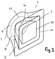
- a diffuser 4 is explained in more detail. It has an annular interface 6 with which the diffuser 4 can be connected to the fan.
- the outer edge 7 of the interface 6 is adjoined by a wall 8 which initially has a circular cross-section and at a distance from the outer edge 7 continuously changes into a quadrangular outline shape.
- the wall 8 has the quadrangular outline over part of its height.
- the single wall 8 is sufficient as a diffuser wall for the diffuser 4 .
- two intermediate walls 9 and 10 are provided which are spaced apart from one another over their height, so that a passage 11 is formed between the two intermediate walls 9 and 10 .
- the passages 11, 12 have a square shape.
- the intermediate walls 9, 10 also have the transition from a circular interface 13, 14 to the square shape like the jacket 8, the square shape being to be understood in the same way as with the wall 8.
- the interfaces 13, 14 have a smaller diameter than the Interface 6, wherein the interface 14 of the inner partition 10 has a smaller diameter than the interface 13 of the central partition 9.
- the interface 14 advantageously has approximately the same diameter as the hub 21 ( 9 ) of the impeller 20.
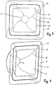
- the walls 8 to 10 are designed in such a way that the outline of the walls increases, preferably increases steadily, in the direction of their free end.
- the walls 8 to 10 thus have the largest outline at the free end.
- the course of the walls 8 to 10 can be designed in such a way that they run at least approximately parallel to one another from the interface 6 , 13 , 14 . However, depending on the flow conditions, the walls 8 to 10 can also be designed in such a way that they do not extend parallel to one another.
- the diffuser 4 can also have only one intermediate wall or more than two intermediate walls.
- the walls have 8 to 10 in accordance with the embodiment 2 same height so that their free ends lie in a common plane.
- the walls 8 to 10 can also be of different heights.
- the height of the walls 8 to 10 decreases from the outside to the inside.
- two of the walls 8 to 10 can also be of the same height and the third wall can be higher or shorter than the other two walls. The height of the walls can thus be optimally adapted to the respective flow conditions in such a way that the outlet losses are minimized.
- the intermediate walls 9, 10 are fixed to each other and to the outer wall 8 in a suitable manner, for example by means of cross members with which the walls are connected to one another.
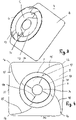
- the four pages 34 to 37 ( 7 ) of walls 8 to 10 continuously merge into one another.
- the transition takes place in such a way that the transition areas 15, 16 between the sides 34 to 37 of the wall 8 are curved over their height. This progression over the height of wall 8 is indicated by lines 15 in 4 marked.
- the transition area 15, 16 extends almost over the entire height of the wall 8.
- the curvature is provided in such a way that the transitions 15, 16 have a twist and follow the flow direction of the air behind the impeller (not shown) of the fan 3.
- the curvature is provided in such a way that the transition regions 15, 16 enclose an angle with a radial of the diffuser, which runs through the rounded corner 16 of the wall 8, over their length.
- transitions 15, 16 Due to the course described, only very small flow losses through the transitions 15, 16 occur at most. Due to the curvature, the transitions 15, 16 follow the swirl of the air flow within the diffuser 4. The transitions 15, 16 extend approximately from the outlet end of the wall 8 to close to the circular outer edge 7 of the interface 6.
- the intermediate walls 9 and 10 are also provided with such transitions 17, 18, which are also designed with a twisting curve in accordance with the course of the air flow behind the impeller and extend from the transition areas between the sides of the partitions 9,10 to near the respective interface 13,14.
- the walls 8 to 10 have a square outline. However, they can also have a rectangular, hexagonal or, for example, a triangular outline.
- the outline shape depends in particular on the shape of the corresponding side of the housing 1 on which the diffusers 4 are provided. The outline of the flow outlet can thus be selected so that the available side of the housing is optimally utilized.
- the nozzle 19 has a circular outline.
- the fan 3 has the impeller 20 with the hub 21 from which the blades 22 protrude at regular intervals. They are advantageously each provided with a winglet 23 on the radially outer edge.
- the rear edge 24 of the wings 22 in the direction of rotation is tooth-like profiled.
- the wings 22 of the impeller 20 can of course also have any other suitable design.
- the diffuser 4 is radially connected to the nozzle 19 of the fan 3, preferably screwed, which is indicated by the dot-dash line 25.
- the nozzle 19 is provided on a nozzle plate 32 which has approximately the same cross section as the free end of the wall 8 .
- the nozzle 19 and the nozzle plate 32 are advantageously formed in one piece with one another, but can also be separate components which are firmly connected to one another in a suitable manner.
- the nozzle plate 32 advantageously has the same angular outline as the outlet end of the wall 8. This allows the Fans 3 are arranged closely behind and / or next to each other.
- the nozzle plates 32 and the walls 8 of the diffusers 4 of adjacent fans 3 can collide here, as is shown in 1 is shown.
- the diffuser 4 has the outer wall 8 and the intermediate walls 9, 10. In axial section, as can be seen from FIG 9 results in the sides of the outer wall 8 being approximately concave.
- the sides of the intermediate wall 9 are approximately straight in axial section, while the sides of the intermediate wall 10 are approximately convex.
- Such a design of the walls 8 to 10 can be provided in all of the exemplary embodiments described.
- guide vanes 26 can be provided in the diffuser 4, which extend between the walls 8 to 10 and are rigidly arranged.
- the guide vanes 26 are located on the side of the radial attachment 25 facing away from the vanes 22 or, in the embodiment according to FIG 10 , the axial attachment.
- the diffuser 4 is pushed with its interface 6 onto or into the nozzle 19 and firmly connected to the nozzle by the radial attachment 25, which is advantageously a screw connection.
- the walls 8 to 10 of the diffuser 4 can be designed to be noise-dampening, so that only a quiet operating noise is produced when the fans are in use.
- the walls 8 to 10 can also be designed to be adjustable, so that their outline shape can be adapted to the flow conditions and/or installation conditions at least over part of their height.
- the walls 8 to 10 can be designed to be flexible over at least part of their height, for example for adjustability.
- the interface 6 of the outer wall 8 can be provided with a radially outwardly extending annular flange 27 which is axially fastened to a radially outwardly extending annular flange 28 at the free end of the nozzle 19 .
- This axial fastening is also advantageous a screw connection that allows the diffuser 4 to be removed from the nozzle 19 if necessary.
- the diffuser 4 can be made relatively short because of the partition walls.
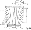
- the air conveyed by the impeller 20 reaches between the walls 8 and 9 or 9 and 10.
- the flow cross section of the passages 11 and 12 initially decreases in the direction of flow until it has its smallest cross section in the region 29 indicated by a dashed line.
- the air is accelerated within this area 29, which leads to an equalization of the air flow.
- the air flow can then be delayed with fewer losses, resulting in a high degree of efficiency of the diffuser 4 .
- From the area 29, the flow cross section of the passages 11, 12 increases in the direction of the outlet end, preferably continuously.
- the narrowing of the cross-section 29 also prevents premature stalling of the flow (collapse of the flow) in the passage 11 and 12.
- the inner partition 10 surrounds a terminal box 30 or a place for the electronics when an external rotor motor is used for the fan 3. In the case of an internal rotor motor, part 30 would be the fan motor.
- the air flow generated by the fan 3 flows through the passages 11, 12.
- the surface of the motor 30 is well cooled by the air flow flowing through the passage 11, as a result of which the electronics or electrical components of the motor are cooled effectively.
- the outer wall 8 of the diffuser 4 is according to the embodiment 11 integrally formed with the nozzle 19.
- the exit area of the two passages 11, 12 is covered by a contact protection 31, which can be formed by a corresponding grid or by individual grid bars.
- the protection against contact 31 is at a large distance from the rotating impeller 20.
- the protection against contact 31 can be designed in such a way that only small pressure losses occur when the air exits the diffuser 4 and only a small amount of noise occurs. In particular, this effect can be achieved in that the contact protection 31 has a correspondingly large mesh size.
- the contact protection 31 described can be provided in all of the described and illustrated embodiments.
- the diffuser 4 of the exemplary embodiments described can be used for evaporators, condensers, air coolers, dry coolers and the like. How based on Figures 9 to 11 described, the diffuser 4 may be provided with a supporting function for accommodating the fan motor 30.
- the fans 3 can be axial or diagonal fans.
- the radius R at the exit end of the wall 8 ( 7 ) is advantageously in a range of ⁇ 0.5 x D, where D is the diameter of the impeller 20 ( 9 ) is.
- the radius R of the rounded corners of the wall 8 is in a range of ⁇ approximately 0.25 ⁇ D.
- the exit surface of the wall 8 is smaller as a result of the rounding of the corners than with a square outline shape at the exit end.
- the area deviation A/A R from the maximum available angular area A is in the range between about 1 and 1.27, preferably in a range between about 1 and about 1.05.
- the efficiency of the diffuser can also be optimally adjusted to the given installation conditions by the ratio of the length L to the diameter D of the fan 3 .
- This length to diameter ratio L/D is in a range of ⁇ 5, preferably in a range from about 0.2 to about 2. This ratio applies to all of the exemplary embodiments described.
- the efficiency of the diffuser 4 can also be influenced by the selection of the inlet and outlet cross sections in relation to one another.
- the entry cross section is denoted by A E and the exit cross section of the diffuser 4 is denoted by A A .
- the ratio of exit area to entry area A A / AE is in a range of less than about 5, advantageously in a range between about 1.2 and about 3. The area ratio applies to all embodiments.
- twist or twist 15, 16; 17, 18 will be through the relationship ⁇ ⁇ D L defined, where the angle ⁇ between the two radials r 1 and r 2 is measured.
- the radial r 1 runs through the intersection between the transition region 15 and the inner free edge 7 of the wall 8.
- the radial r 2 runs in contrast to the corner region of the wall 8 lying in the exit surface, from which the transition region 15 extends. That twist or twist ⁇ ⁇ D L lies in a range between 0° and 360°, but advantageously in a range between approximately 50° and 100°.
Landscapes
- Engineering & Computer Science (AREA)
- Mechanical Engineering (AREA)
- General Engineering & Computer Science (AREA)
- Physics & Mathematics (AREA)
- Fluid Mechanics (AREA)
- Structures Of Non-Positive Displacement Pumps (AREA)
- Nozzles (AREA)
- Duct Arrangements (AREA)
Claims (19)
- Diffuseur comportant au moins une paroi (8), qui renferme une entrée avec une section transversale ronde, qui se confond de manière continue sur la hauteur de la paroi (8) du diffuseur (4) avec une section transversale angulaire à la sortie du diffuseur (4), caractérisé en ce que les transitions (15) entre les côtés (34 à 37) de la paroi (8) présentent une torsion dans le sens de la hauteur, qui suit le tourbillon du flux d'air à travers le diffuseur.
- Diffuseur selon la revendication 1,
caractérisé en ce que la section transversale du diffuseur (4) d'abord diminue puis augmente à partir d'une extrémité d'entrée (6) - Diffuseur selon la revendication 1 ou 2,
caractérisé en ce que la section transversale angulaire est prévue sur plus du quart de la hauteur de la paroi (8). - Diffuseur selon une des revendications 1 à 3,
caractérisé en ce que le diffuseur (4) comporte au moins une autre paroi (9, 10) qui est entourée par la paroi (8) à distance. - Diffuseur selon la revendication 4,
caractérisé en ce que la paroi supplémentaire (9, 10) présente une section transversale angulaire au moins à la sortie. - Diffuseur selon une des revendications 4 ou 5,
caractérisé en ce que la paroi supplémentaire à l'entrée possède de préférence une section transversale circulaire, de préférence ronde qui se confond de manière continue avec la section transversale angulaire sur la hauteur de la paroi supplémentaire (9, 10). - Diffuseur selon une quelconque des revendications 4 à 6, caractérisé en ce que les transitions (17, 18) entre les côtés de la paroi supplémentaire (9, 10) dans le sens de la hauteur présentent un tourbillon.
- Diffuseur selon la revendication 1,
caractérisé en ce que les transitions (15) entre les côtés (34 à 37) de la paroi (8) présentent une torsion verticale (15 à 18) qui vérifie la relation
- Diffuseur selon une des revendications 4 à 7,
caractérisé en ce que la paroi (8) entoure la paroi supplémentaire (9, 10, 38, 41) en formant un passage (11, 12,'39, 40) et que les extrémités de sortie des parois (8 à 10, 38, 41) diffèrent en hauteurs pour agrandir la surface de sortie (AA) du diffuseur (4). - Diffuseur selon la revendication 9,
caractérisé en ce que les extrémités de sortie des parois (8 à 10, 38, 41) se trouvent dans une surface incurvée, telle qu'une surface sphérique ou cylindrique (45). - Diffuseur selon la revendication 9,
caractérisé en ce que les extrémités de sortie des parois (8 à 10, 38, 41) se trouvent dans des surfaces planes qui sont, par exemple, les surfaces latérales d'un parallélépipède imaginaire (44) ou d'une pyramide. - Diffuseur selon une des revendications 9 à 11,
caractérisé en ce qu'au moins une ouverture (47, 48, 49) est ménagée dans au moins une paroi (8 à 10, 38, 41), à travers laquelle des passages adjacents (11, 12, 39 40) sont reliés fluidiquement les uns aux autres. - Ventilateur comportant une roue (20) et diffuseur (4) selon une quelconque des revendications 1 à 12.
- Ventilateur comportant une roue (20) et un diffuseur (4) selon la revendication 1,
caractérisé en ce que les transitions (15) à l'extrémité de sortie entre les côtés (34 à 37) de la paroi (8) possèdent une courbure (R), qui est dans une plage d'environ <0,5 x D, de préférence dans une plage d'environ <0,25 x D, dans lequel (D) est le diamètre de la roue (20). - Ventilateur selon la revendication 14,
caractérisé en ce que la surface de sortie (AR) de la paroi (8) comportant la transition arrondie (15) est plus petite que la surface de sortie (A) de la paroi (8) sans transition arrondie (15) à l'extrémité de sortie entre les côtés (34 à 37) de la paroi (8), dans lequel l'écart de surface (A/AR) est compris dans la plage entre environ 1 et environ 1,27, de préférence entre environ 1 et environ 1,05. - Dispositif comportant au moins un ventilateur selon une des revendications 13 à 15.
- Dispositif selon la revendication 16,
caractérisé en ce que sur le côté supérieur (5) de la paroi latérale du boîtier au moins un autre ventilateur (3) comportant un diffuseur (4) est agencé. - Dispositif selon la revendication 16 ou 17,
caractérisé en ce que les diffuseurs (4) possèdent une section transversale de sortie angulaire. - Dispositif selon une des revendications 16 à 18,
caractérisé en ce que des diffuseurs adjacents (4) sont juxtaposés par leurs côtés de contour.
Priority Applications (1)
| Application Number | Priority Date | Filing Date | Title |
|---|---|---|---|
| SI201332008T SI2815130T1 (sl) | 2012-02-17 | 2013-02-15 | Difusor, ventilator s takim difuzorjem, kot tudi naprava s takimi ventilatorji |
Applications Claiming Priority (2)
| Application Number | Priority Date | Filing Date | Title |
|---|---|---|---|
| DE102012003336A DE102012003336A1 (de) | 2012-02-17 | 2012-02-17 | Diffusor, Ventilator mit einem solchen Diffusor sowie Gerät mit solchen Ventilatoren |
| PCT/EP2013/000453 WO2013120623A2 (fr) | 2012-02-17 | 2013-02-15 | Diffuseur, ventilateur comportant un tel diffuseur et appareil comprenant de tels ventilateurs |
Publications (2)
| Publication Number | Publication Date |
|---|---|
| EP2815130A2 EP2815130A2 (fr) | 2014-12-24 |
| EP2815130B1 true EP2815130B1 (fr) | 2022-06-01 |
Family
ID=48914970
Family Applications (1)
| Application Number | Title | Priority Date | Filing Date |
|---|---|---|---|
| EP13748807.8A Active EP2815130B1 (fr) | 2012-02-17 | 2013-02-15 | Diffuseur, ventilateur comportant un tel diffuseur et appareil comprenant de tels ventilateurs |
Country Status (9)
| Country | Link |
|---|---|
| US (1) | US10197070B2 (fr) |
| EP (1) | EP2815130B1 (fr) |
| JP (1) | JP6357424B2 (fr) |
| CN (1) | CN104302927B (fr) |
| DE (1) | DE102012003336A1 (fr) |
| ES (1) | ES2922729T3 (fr) |
| RU (1) | RU2620308C2 (fr) |
| SI (1) | SI2815130T1 (fr) |
| WO (1) | WO2013120623A2 (fr) |
Families Citing this family (22)
| Publication number | Priority date | Publication date | Assignee | Title |
|---|---|---|---|---|
| JP6385752B2 (ja) | 2013-12-02 | 2018-09-05 | 三星電子株式会社Samsung Electronics Co.,Ltd. | 送風装置及び空気調和装置用室外機 |
| CN106016648A (zh) * | 2016-07-04 | 2016-10-12 | 珠海格力电器股份有限公司 | 一种出风框以及风管机 |
| DE102017104779A1 (de) | 2017-03-07 | 2018-09-13 | Ebm-Papst Mulfingen Gmbh & Co. Kg | Luftleitanordnung |
| US10822101B2 (en) * | 2017-07-21 | 2020-11-03 | General Electric Company | Vertical takeoff and landing aircraft having a forward thrust propulsor |
| JP7068609B2 (ja) * | 2018-05-31 | 2022-05-17 | 株式会社富士通ゼネラル | 天井埋込型空気調和機 |
| DE102018211809A1 (de) * | 2018-07-16 | 2020-01-16 | Ziehl-Abegg Se | Gehäuse für einen Ventilator und Ventilator |
| US11352132B2 (en) * | 2018-07-23 | 2022-06-07 | General Electric Company | Lift fan with diffuser duct |
| US10883174B2 (en) * | 2018-11-27 | 2021-01-05 | Applied Materials, Inc. | Gas diffuser mounting plate for reduced particle generation |
| CN111219789B (zh) * | 2018-11-27 | 2021-07-23 | 宁波奥克斯电气股份有限公司 | 一种吸风板安装结构及空调 |
| CN109484644A (zh) * | 2018-12-27 | 2019-03-19 | 酷黑科技(北京)有限公司 | 一种涵道式飞行器及涵道扩散器 |
| KR102028935B1 (ko) * | 2019-01-17 | 2019-10-07 | 김봉교 | 디퓨져를 구비한 강화 유리 제조 장치 및 제조 방법 |
| US11448418B2 (en) | 2019-03-11 | 2022-09-20 | Air Distribution Technologies Ip, Llc | Undulated surface enhancement of diffuser blades for linear bar diffuser |
| US11441811B2 (en) | 2019-03-11 | 2022-09-13 | Air Distribution Technologies Ip, Llc | Undulated surface enhancement of diffuser blade for plenum slot diffuser |
| US11435111B2 (en) | 2019-03-11 | 2022-09-06 | Air Distribution Technologies Ip, Llc | Undulated surface enhancement of diffuser blades for round and rectangular ceiling diffuser |
| CN110360475A (zh) * | 2019-08-09 | 2019-10-22 | 佛山市清源科技有限公司 | 具有静音大风量风道结构的照明装置 |
| KR102377336B1 (ko) * | 2020-06-09 | 2022-03-21 | 나명환 | 송풍기용 공기 증폭 송출장치 |
| US11846434B2 (en) | 2020-07-16 | 2023-12-19 | Best Technologies, Inc. | Air handler devices with U-bend design |
| US11346564B2 (en) | 2020-07-16 | 2022-05-31 | Best Technologies, Inc. | HVAC devices with improved design and functionality |
| CN112610530A (zh) * | 2021-01-07 | 2021-04-06 | 泛仕达机电股份有限公司 | 一种扭曲扩散筒及应用该扩散筒的轴流风机 |
| CN112902423B (zh) * | 2021-02-06 | 2022-07-08 | 西安建筑科技大学 | 一种圆形散流装置 |
| DE102021104615A1 (de) * | 2021-02-26 | 2022-09-01 | Robert Bosch Gesellschaft mit beschränkter Haftung | Vorrichtung zum Durchströmen einer Komponente einer Klimaanlage oder einer Heizanlage, Schutzgitter und Wärmepumpen-Außeneinheit |
| CN113623249B (zh) * | 2021-08-26 | 2022-10-28 | 西安交通大学 | 一种采用矩形出口扩散筒内设隔板的并联式高效轴流风机 |
Citations (3)
| Publication number | Priority date | Publication date | Assignee | Title |
|---|---|---|---|---|
| US2209121A (en) * | 1938-12-31 | 1940-07-23 | Anemostat Corp America | Fluid distributing device |
| US2750865A (en) * | 1951-02-14 | 1956-06-19 | Allied Thermal Corp | Diffuser |
| US20110217164A1 (en) * | 2010-03-08 | 2011-09-08 | Robert Bosch Gmbh | Axial cooling fan shroud |
Family Cites Families (29)
| Publication number | Priority date | Publication date | Assignee | Title |
|---|---|---|---|---|
| US1940790A (en) * | 1930-10-18 | 1933-12-26 | Walter S Diehl | Fluid conducting passage |
| US2144035A (en) | 1935-09-20 | 1939-01-17 | Bendix Prod Corp | Fan blast transformer |
| GB788581A (en) * | 1955-02-24 | 1958-01-02 | & De Realisations Ind Seri Fou | Improvements in and relating to fans and ventilating plants |
| JPS4829708Y1 (fr) * | 1970-12-18 | 1973-09-10 | ||
| JPS49142661U (fr) * | 1973-04-02 | 1974-12-09 | ||
| SU623998A1 (ru) * | 1977-03-04 | 1978-09-15 | Центральный научно-исследовательский и проектно-экспериментальный институт промышленных зданий и сооружений | Кольцевой диффузор осевого вентил тора |
| JPS547040U (fr) * | 1977-06-16 | 1979-01-18 | ||
| JPS5426860U (fr) * | 1977-07-26 | 1979-02-21 | ||
| DE3515441A1 (de) | 1985-04-29 | 1986-10-30 | Dieter Prof. Dr.-Ing. 7500 Karlsruhe Wurz | Ventilatorkuehler |
| US4714009A (en) * | 1986-08-04 | 1987-12-22 | Philips Industries Inc. | Ceiling air diffuser |
| DE8705665U1 (de) * | 1987-04-16 | 1987-06-11 | Knürr-Mechanik für die Elektronik AG, 8000 München | Lüftereinschub |
| US5117745A (en) * | 1990-03-06 | 1992-06-02 | Carnes Company, Inc. | Safety lock |
| JPH0542949U (ja) * | 1991-11-06 | 1993-06-11 | 株式会社フジタ | 制気口の風量温度測定装置 |
| FR2683599B1 (fr) * | 1991-11-07 | 1994-03-04 | Ecia | Carenage perfectionne pour ventilateur et son application a un groupe motoventilateur d'automobile. |
| FR2697287B1 (fr) * | 1992-10-26 | 1994-12-09 | Europ Gas Turbines Sa | Diffuseur d'échappement de turbine à gaz. |
| FR2728028B1 (fr) | 1994-12-07 | 1997-03-14 | Sardou Max | Dispositif pour transformer l'energie mecanique d'un moteur en une mise sous pression d'un gaz |
| JP3223099B2 (ja) | 1996-02-26 | 2001-10-29 | 三洋電機株式会社 | 冷凍装置 |
| US5791876A (en) * | 1997-03-25 | 1998-08-11 | Behr America, Inc. | Floating drive assembly for an automotive cooling fan |
| US5740766A (en) * | 1997-03-25 | 1998-04-21 | Behr America, Inc. | Automotive fan and shroud assembly |
| US6193603B1 (en) * | 1999-10-07 | 2001-02-27 | Kuo-Cheng Tai | Wind outlet plate of an air conditioner for cleaning air |
| US6676371B1 (en) * | 2002-08-22 | 2004-01-13 | Custom Molders, Inc. | Double barrel vehicle cooling fan shroud |
| US6776710B1 (en) * | 2003-10-24 | 2004-08-17 | Unico, Inc. | Vent structure for slotted outlet with uniform velocity profile |
| FR2874409B1 (fr) | 2004-08-19 | 2006-10-13 | Max Sardou | Ventilateur de tunnel |
| JP2007040562A (ja) | 2005-08-01 | 2007-02-15 | Takasago Thermal Eng Co Ltd | 冷暖自動切換角型アネモ |
| US8221074B2 (en) * | 2007-12-21 | 2012-07-17 | Paccar Inc | Fan ring shroud assembly |
| FR2934009B1 (fr) * | 2008-07-21 | 2010-09-03 | Ge Energy Products France Snc | Diffuseur d'echappement pour turbine a gaz |
| CN201723504U (zh) * | 2010-06-09 | 2011-01-26 | 张崇臣 | 一种用于风扇的导流静音装置 |
| DE202011004708U1 (de) | 2010-08-12 | 2011-07-14 | Ziehl-Abegg Ag | Ventilator |
| DE202010016820U1 (de) * | 2010-12-21 | 2012-03-26 | Ebm-Papst Mulfingen Gmbh & Co. Kg | Diffusor für einen Ventilator sowie Ventilatoranordnung mit einem derartigen Diffusor |
-
2012
- 2012-02-17 DE DE102012003336A patent/DE102012003336A1/de active Pending
-
2013
- 2013-02-15 US US14/379,292 patent/US10197070B2/en active Active
- 2013-02-15 SI SI201332008T patent/SI2815130T1/sl unknown
- 2013-02-15 CN CN201380020001.6A patent/CN104302927B/zh active Active
- 2013-02-15 RU RU2014137394A patent/RU2620308C2/ru active
- 2013-02-15 EP EP13748807.8A patent/EP2815130B1/fr active Active
- 2013-02-15 ES ES13748807T patent/ES2922729T3/es active Active
- 2013-02-15 WO PCT/EP2013/000453 patent/WO2013120623A2/fr active Application Filing
- 2013-02-15 JP JP2014556956A patent/JP6357424B2/ja active Active
Patent Citations (3)
| Publication number | Priority date | Publication date | Assignee | Title |
|---|---|---|---|---|
| US2209121A (en) * | 1938-12-31 | 1940-07-23 | Anemostat Corp America | Fluid distributing device |
| US2750865A (en) * | 1951-02-14 | 1956-06-19 | Allied Thermal Corp | Diffuser |
| US20110217164A1 (en) * | 2010-03-08 | 2011-09-08 | Robert Bosch Gmbh | Axial cooling fan shroud |
Also Published As
| Publication number | Publication date |
|---|---|
| DE102012003336A1 (de) | 2013-08-22 |
| RU2620308C2 (ru) | 2017-05-24 |
| RU2014137394A (ru) | 2016-04-10 |
| US10197070B2 (en) | 2019-02-05 |
| ES2922729T3 (es) | 2022-09-19 |
| JP6357424B2 (ja) | 2018-07-11 |
| SI2815130T1 (sl) | 2022-10-28 |
| WO2013120623A8 (fr) | 2014-10-02 |
| WO2013120623A3 (fr) | 2014-08-07 |
| EP2815130A2 (fr) | 2014-12-24 |
| JP2015508884A (ja) | 2015-03-23 |
| CN104302927B (zh) | 2019-10-11 |
| WO2013120623A2 (fr) | 2013-08-22 |
| CN104302927A (zh) | 2015-01-21 |
| US20150300372A1 (en) | 2015-10-22 |
Similar Documents
| Publication | Publication Date | Title |
|---|---|---|
| EP2815130B1 (fr) | Diffuseur, ventilateur comportant un tel diffuseur et appareil comprenant de tels ventilateurs | |
| EP2338581B1 (fr) | Unité de ventilateur pour ventilateur à filtre | |
| EP3255281B1 (fr) | Ventilateur avec aubes de diffuseur tandem | |
| EP2904277B1 (fr) | Redresseur d'écoulement pour un ventilateur axial | |
| EP1895166B1 (fr) | Appareil d'homogénisation d'un courant pour un ventilateur | |
| EP2904270B1 (fr) | Boîtier pour un ventilateur axial | |
| EP2778432A1 (fr) | Redresseur de courant | |
| WO2018113855A1 (fr) | Module de ventilation ainsi qu'agencement d'un ou de plusieurs desdits modules de ventilation dans un canal d'écoulement | |
| DE202014011464U1 (de) | Gebläseeinrichtung und Außeneinheit einer Klimaanlage, welche diese umfasst | |
| EP3298284B1 (fr) | Grille de guidage d'écoulement plane | |
| EP3775565B1 (fr) | Ventilateur diagonal compact avec dispositif de guidage aval | |
| EP2559905A2 (fr) | Suspension de moteur pour ventilateurs, de préférence ventilateurs axiaux, ainsi que procédé de fabrication d'une grille d'aération d'une telle suspension de moteur | |
| EP2597029A2 (fr) | Pré-buse pour propulsion de véhicule nautique afin d'améliorer l'efficience énergétique | |
| EP3183459A1 (fr) | Ventilateur axial | |
| CH704212A1 (de) | Axialkompressor. | |
| WO2020015800A1 (fr) | Enveloppe de ventilateur et ventilateur | |
| EP3009682A1 (fr) | Ventilateur axial avec diffuseur interne et externe | |
| EP3592987B1 (fr) | Carter semi-hélicoïdal | |
| EP2716916B1 (fr) | Unité de ventilateur | |
| EP4090853A1 (fr) | Boîtier pour un ventilateur et ventilateur doté d'un boîtier correspondant | |
| DE102014104725A1 (de) | Rotor und Fluidturbine mit Rotor | |
| DE102020200363A1 (de) | Tragmodul für einen Ventilator und Ventilator mit einem entsprechenden Tragmodul | |
| DE4243932C2 (de) | Schutzgitter für Freispiegelgerinne | |
| DE102016214467A1 (de) | Ventilatoreinheit und Anordnung mit mindestens zwei Ventilatoreinheiten | |
| DE102016116832A1 (de) | Schlitzauslass für Luftschott-Anlagen |
Legal Events
| Date | Code | Title | Description |
|---|---|---|---|
| PUAI | Public reference made under article 153(3) epc to a published international application that has entered the european phase |
Free format text: ORIGINAL CODE: 0009012 |
|
| 17P | Request for examination filed |
Effective date: 20140811 |
|
| AK | Designated contracting states |
Kind code of ref document: A2 Designated state(s): AL AT BE BG CH CY CZ DE DK EE ES FI FR GB GR HR HU IE IS IT LI LT LU LV MC MK MT NL NO PL PT RO RS SE SI SK SM TR |
|
| AX | Request for extension of the european patent |
Extension state: BA ME |
|
| R17P | Request for examination filed (corrected) |
Effective date: 20150209 |
|
| RBV | Designated contracting states (corrected) |
Designated state(s): AL AT BE BG CH CY CZ DE DK EE ES FI FR GB GR HR HU IE IS IT LI LT LU LV MC MK MT NL NO PL PT RO RS SE SI SK SM TR |
|
| DAX | Request for extension of the european patent (deleted) | ||
| STAA | Information on the status of an ep patent application or granted ep patent |
Free format text: STATUS: EXAMINATION IS IN PROGRESS |
|
| 17Q | First examination report despatched |
Effective date: 20181203 |
|
| STAA | Information on the status of an ep patent application or granted ep patent |
Free format text: STATUS: EXAMINATION IS IN PROGRESS |
|
| GRAP | Despatch of communication of intention to grant a patent |
Free format text: ORIGINAL CODE: EPIDOSNIGR1 |
|
| STAA | Information on the status of an ep patent application or granted ep patent |
Free format text: STATUS: GRANT OF PATENT IS INTENDED |
|
| INTG | Intention to grant announced |
Effective date: 20220105 |
|
| GRAS | Grant fee paid |
Free format text: ORIGINAL CODE: EPIDOSNIGR3 |
|
| GRAA | (expected) grant |
Free format text: ORIGINAL CODE: 0009210 |
|
| STAA | Information on the status of an ep patent application or granted ep patent |
Free format text: STATUS: THE PATENT HAS BEEN GRANTED |
|
| AK | Designated contracting states |
Kind code of ref document: B1 Designated state(s): AL AT BE BG CH CY CZ DE DK EE ES FI FR GB GR HR HU IE IS IT LI LT LU LV MC MK MT NL NO PL PT RO RS SE SI SK SM TR |
|
| REG | Reference to a national code |
Ref country code: GB Ref legal event code: FG4D Free format text: NOT ENGLISH |
|
| REG | Reference to a national code |
Ref country code: AT Ref legal event code: REF Ref document number: 1495535 Country of ref document: AT Kind code of ref document: T Effective date: 20220615 Ref country code: CH Ref legal event code: EP Ref country code: DE Ref legal event code: R096 Ref document number: 502013016157 Country of ref document: DE |
|
| REG | Reference to a national code |
Ref country code: IE Ref legal event code: FG4D Free format text: LANGUAGE OF EP DOCUMENT: GERMAN |
|
| REG | Reference to a national code |
Ref country code: ES Ref legal event code: FG2A Ref document number: 2922729 Country of ref document: ES Kind code of ref document: T3 Effective date: 20220919 |
|
| REG | Reference to a national code |
Ref country code: LT Ref legal event code: MG9D |
|
| REG | Reference to a national code |
Ref country code: NL Ref legal event code: MP Effective date: 20220601 |
|
| PG25 | Lapsed in a contracting state [announced via postgrant information from national office to epo] |
Ref country code: SE Free format text: LAPSE BECAUSE OF FAILURE TO SUBMIT A TRANSLATION OF THE DESCRIPTION OR TO PAY THE FEE WITHIN THE PRESCRIBED TIME-LIMIT Effective date: 20220601 Ref country code: NO Free format text: LAPSE BECAUSE OF FAILURE TO SUBMIT A TRANSLATION OF THE DESCRIPTION OR TO PAY THE FEE WITHIN THE PRESCRIBED TIME-LIMIT Effective date: 20220901 Ref country code: LT Free format text: LAPSE BECAUSE OF FAILURE TO SUBMIT A TRANSLATION OF THE DESCRIPTION OR TO PAY THE FEE WITHIN THE PRESCRIBED TIME-LIMIT Effective date: 20220601 Ref country code: HR Free format text: LAPSE BECAUSE OF FAILURE TO SUBMIT A TRANSLATION OF THE DESCRIPTION OR TO PAY THE FEE WITHIN THE PRESCRIBED TIME-LIMIT Effective date: 20220601 Ref country code: GR Free format text: LAPSE BECAUSE OF FAILURE TO SUBMIT A TRANSLATION OF THE DESCRIPTION OR TO PAY THE FEE WITHIN THE PRESCRIBED TIME-LIMIT Effective date: 20220902 Ref country code: FI Free format text: LAPSE BECAUSE OF FAILURE TO SUBMIT A TRANSLATION OF THE DESCRIPTION OR TO PAY THE FEE WITHIN THE PRESCRIBED TIME-LIMIT Effective date: 20220601 Ref country code: BG Free format text: LAPSE BECAUSE OF FAILURE TO SUBMIT A TRANSLATION OF THE DESCRIPTION OR TO PAY THE FEE WITHIN THE PRESCRIBED TIME-LIMIT Effective date: 20220901 |
|
| PG25 | Lapsed in a contracting state [announced via postgrant information from national office to epo] |
Ref country code: RS Free format text: LAPSE BECAUSE OF FAILURE TO SUBMIT A TRANSLATION OF THE DESCRIPTION OR TO PAY THE FEE WITHIN THE PRESCRIBED TIME-LIMIT Effective date: 20220601 Ref country code: PL Free format text: LAPSE BECAUSE OF FAILURE TO SUBMIT A TRANSLATION OF THE DESCRIPTION OR TO PAY THE FEE WITHIN THE PRESCRIBED TIME-LIMIT Effective date: 20220601 Ref country code: LV Free format text: LAPSE BECAUSE OF FAILURE TO SUBMIT A TRANSLATION OF THE DESCRIPTION OR TO PAY THE FEE WITHIN THE PRESCRIBED TIME-LIMIT Effective date: 20220601 |
|
| PG25 | Lapsed in a contracting state [announced via postgrant information from national office to epo] |
Ref country code: NL Free format text: LAPSE BECAUSE OF FAILURE TO SUBMIT A TRANSLATION OF THE DESCRIPTION OR TO PAY THE FEE WITHIN THE PRESCRIBED TIME-LIMIT Effective date: 20220601 |
|
| REG | Reference to a national code |
Ref country code: FR Ref legal event code: PLFP Year of fee payment: 11 |
|
| PG25 | Lapsed in a contracting state [announced via postgrant information from national office to epo] |
Ref country code: SM Free format text: LAPSE BECAUSE OF FAILURE TO SUBMIT A TRANSLATION OF THE DESCRIPTION OR TO PAY THE FEE WITHIN THE PRESCRIBED TIME-LIMIT Effective date: 20220601 Ref country code: SK Free format text: LAPSE BECAUSE OF FAILURE TO SUBMIT A TRANSLATION OF THE DESCRIPTION OR TO PAY THE FEE WITHIN THE PRESCRIBED TIME-LIMIT Effective date: 20220601 Ref country code: RO Free format text: LAPSE BECAUSE OF FAILURE TO SUBMIT A TRANSLATION OF THE DESCRIPTION OR TO PAY THE FEE WITHIN THE PRESCRIBED TIME-LIMIT Effective date: 20220601 Ref country code: PT Free format text: LAPSE BECAUSE OF FAILURE TO SUBMIT A TRANSLATION OF THE DESCRIPTION OR TO PAY THE FEE WITHIN THE PRESCRIBED TIME-LIMIT Effective date: 20221003 Ref country code: EE Free format text: LAPSE BECAUSE OF FAILURE TO SUBMIT A TRANSLATION OF THE DESCRIPTION OR TO PAY THE FEE WITHIN THE PRESCRIBED TIME-LIMIT Effective date: 20220601 Ref country code: CZ Free format text: LAPSE BECAUSE OF FAILURE TO SUBMIT A TRANSLATION OF THE DESCRIPTION OR TO PAY THE FEE WITHIN THE PRESCRIBED TIME-LIMIT Effective date: 20220601 |
|
| PG25 | Lapsed in a contracting state [announced via postgrant information from national office to epo] |
Ref country code: IS Free format text: LAPSE BECAUSE OF FAILURE TO SUBMIT A TRANSLATION OF THE DESCRIPTION OR TO PAY THE FEE WITHIN THE PRESCRIBED TIME-LIMIT Effective date: 20221001 |
|
| REG | Reference to a national code |
Ref country code: DE Ref legal event code: R097 Ref document number: 502013016157 Country of ref document: DE |
|
| PG25 | Lapsed in a contracting state [announced via postgrant information from national office to epo] |
Ref country code: AL Free format text: LAPSE BECAUSE OF FAILURE TO SUBMIT A TRANSLATION OF THE DESCRIPTION OR TO PAY THE FEE WITHIN THE PRESCRIBED TIME-LIMIT Effective date: 20220601 |
|
| PLBE | No opposition filed within time limit |
Free format text: ORIGINAL CODE: 0009261 |
|
| STAA | Information on the status of an ep patent application or granted ep patent |
Free format text: STATUS: NO OPPOSITION FILED WITHIN TIME LIMIT |
|
| PG25 | Lapsed in a contracting state [announced via postgrant information from national office to epo] |
Ref country code: DK Free format text: LAPSE BECAUSE OF FAILURE TO SUBMIT A TRANSLATION OF THE DESCRIPTION OR TO PAY THE FEE WITHIN THE PRESCRIBED TIME-LIMIT Effective date: 20220601 |
|
| 26N | No opposition filed |
Effective date: 20230302 |
|
| PG25 | Lapsed in a contracting state [announced via postgrant information from national office to epo] |
Ref country code: MC Free format text: LAPSE BECAUSE OF FAILURE TO SUBMIT A TRANSLATION OF THE DESCRIPTION OR TO PAY THE FEE WITHIN THE PRESCRIBED TIME-LIMIT Effective date: 20220601 |
|
| REG | Reference to a national code |
Ref country code: CH Ref legal event code: PL |
|
| REG | Reference to a national code |
Ref country code: BE Ref legal event code: MM Effective date: 20230228 |
|
| PG25 | Lapsed in a contracting state [announced via postgrant information from national office to epo] |
Ref country code: LU Free format text: LAPSE BECAUSE OF NON-PAYMENT OF DUE FEES Effective date: 20230215 Ref country code: LI Free format text: LAPSE BECAUSE OF NON-PAYMENT OF DUE FEES Effective date: 20230228 Ref country code: CH Free format text: LAPSE BECAUSE OF NON-PAYMENT OF DUE FEES Effective date: 20230228 |
|
| P01 | Opt-out of the competence of the unified patent court (upc) registered |
Effective date: 20231115 |
|
| REG | Reference to a national code |
Ref country code: IE Ref legal event code: MM4A |
|
| PGFP | Annual fee paid to national office [announced via postgrant information from national office to epo] |
Ref country code: GB Payment date: 20231222 Year of fee payment: 12 |
|
| PG25 | Lapsed in a contracting state [announced via postgrant information from national office to epo] |
Ref country code: IE Free format text: LAPSE BECAUSE OF NON-PAYMENT OF DUE FEES Effective date: 20230215 |
|
| PGFP | Annual fee paid to national office [announced via postgrant information from national office to epo] |
Ref country code: FR Payment date: 20231221 Year of fee payment: 12 |
|
| PG25 | Lapsed in a contracting state [announced via postgrant information from national office to epo] |
Ref country code: BE Free format text: LAPSE BECAUSE OF NON-PAYMENT OF DUE FEES Effective date: 20230228 |
|
| REG | Reference to a national code |
Ref country code: AT Ref legal event code: MM01 Ref document number: 1495535 Country of ref document: AT Kind code of ref document: T Effective date: 20230215 |
|
| PGFP | Annual fee paid to national office [announced via postgrant information from national office to epo] |
Ref country code: ES Payment date: 20240305 Year of fee payment: 12 |
|
| PG25 | Lapsed in a contracting state [announced via postgrant information from national office to epo] |
Ref country code: AT Free format text: LAPSE BECAUSE OF NON-PAYMENT OF DUE FEES Effective date: 20230215 |
|
| PG25 | Lapsed in a contracting state [announced via postgrant information from national office to epo] |
Ref country code: AT Free format text: LAPSE BECAUSE OF NON-PAYMENT OF DUE FEES Effective date: 20230215 |
|
| PGFP | Annual fee paid to national office [announced via postgrant information from national office to epo] |
Ref country code: SI Payment date: 20231227 Year of fee payment: 12 |
|
| PGFP | Annual fee paid to national office [announced via postgrant information from national office to epo] |
Ref country code: IT Payment date: 20240219 Year of fee payment: 12 |
|
| PGFP | Annual fee paid to national office [announced via postgrant information from national office to epo] |
Ref country code: DE Payment date: 20240426 Year of fee payment: 12 |