EP3254804A2 - Dispositif et procédé destinés à rogner des plaques de verre - Google Patents
Dispositif et procédé destinés à rogner des plaques de verre Download PDFInfo
- Publication number
- EP3254804A2 EP3254804A2 EP17175134.0A EP17175134A EP3254804A2 EP 3254804 A2 EP3254804 A2 EP 3254804A2 EP 17175134 A EP17175134 A EP 17175134A EP 3254804 A2 EP3254804 A2 EP 3254804A2
- Authority
- EP
- European Patent Office
- Prior art keywords
- grinding wheel
- grinding
- glass sheet
- linear motor
- pivot
- Prior art date
- Legal status (The legal status is an assumption and is not a legal conclusion. Google has not performed a legal analysis and makes no representation as to the accuracy of the status listed.)
- Withdrawn
Links
Images


Classifications
-
- B—PERFORMING OPERATIONS; TRANSPORTING
- B24—GRINDING; POLISHING
- B24B—MACHINES, DEVICES, OR PROCESSES FOR GRINDING OR POLISHING; DRESSING OR CONDITIONING OF ABRADING SURFACES; FEEDING OF GRINDING, POLISHING, OR LAPPING AGENTS
- B24B9/00—Machines or devices designed for grinding edges or bevels on work or for removing burrs; Accessories therefor
- B24B9/02—Machines or devices designed for grinding edges or bevels on work or for removing burrs; Accessories therefor characterised by a special design with respect to properties of materials specific to articles to be ground
- B24B9/06—Machines or devices designed for grinding edges or bevels on work or for removing burrs; Accessories therefor characterised by a special design with respect to properties of materials specific to articles to be ground of non-metallic inorganic material, e.g. stone, ceramics, porcelain
- B24B9/08—Machines or devices designed for grinding edges or bevels on work or for removing burrs; Accessories therefor characterised by a special design with respect to properties of materials specific to articles to be ground of non-metallic inorganic material, e.g. stone, ceramics, porcelain of glass
- B24B9/10—Machines or devices designed for grinding edges or bevels on work or for removing burrs; Accessories therefor characterised by a special design with respect to properties of materials specific to articles to be ground of non-metallic inorganic material, e.g. stone, ceramics, porcelain of glass of plate glass
-
- B—PERFORMING OPERATIONS; TRANSPORTING
- B24—GRINDING; POLISHING
- B24B—MACHINES, DEVICES, OR PROCESSES FOR GRINDING OR POLISHING; DRESSING OR CONDITIONING OF ABRADING SURFACES; FEEDING OF GRINDING, POLISHING, OR LAPPING AGENTS
- B24B41/00—Component parts such as frames, beds, carriages, headstocks
- B24B41/04—Headstocks; Working-spindles; Features relating thereto
- B24B41/047—Grinding heads for working on plane surfaces
- B24B41/053—Grinding heads for working on plane surfaces for grinding or polishing glass
Definitions
- the invention relates to a device for trimming glass sheets with at least one grinding head and the features specified in the preamble of claim 1 and of a method for trimming a glass sheet with a rotating grinding wheel and the features specified in the preamble of claim 11.
- the known device contains a plurality of grinding heads.
- Each grinding head has a carrier, on which two grinding wheel drives are arranged with drive shafts oriented perpendicular to each other.
- a grinding wheel is arranged, which has on its flat end face an abrasive surface for the removal of glass material from a glass panel edge.
- the two grinding surfaces are also arranged perpendicular to each other and the grinding head is the glass panel edge delivered such that the glass panel edge between the two grinding wheels, so that each of the grinding wheels can grind a chamfer to an edge of the glass sheet.
- each grinding wheel drive is attached to a motor mount, which is attached to the carrier in a complex manner such that the grinding wheels are movable relative to the carrier.
- spindle drives the two grinding wheels are displaceable together with their drive motors at right angles to the running plane of the glass sheets and thereby allow adaptation to different thicknesses of glass sheets.
- combined spring and damping devices are arranged between the carrier and the motor mounts, which extend parallel to the running plane of the glass sheets and represent a combination of springs with a damping cylinder, which ensure a sufficiently uniform, resilient pressure of the grinding wheels to the glass edges to be processed. A wear of the grinding wheels on their grinding surface can be compensated by a manual readjustment of the grinding wheels, wherein the operation of the trimming device must be interrupted.
- the invention has the object to improve a device and a method of the type mentioned.
- a device for trimming glass panels contains at least one grinding head.
- the grinding head includes a carrier and at least one arranged on the carrier and movable relative to the carrier motor mount.
- a grinding wheel drive in particular in the form of an electric motor, and arranged with the grinding wheel drive grinding wheel are arranged.
- the grinding wheel has a, in particular flat, grinding surface for removing glass material from a glass sheet edge.
- the grinding head has at least one electrical Linear motor, which is coupled to both the carrier and with the motor mount.
- the motor mount and the grinding wheel arranged thereon are displaceable relative to the carrier by means of the linear motor along a feed direction running transversely to the grinding surface of the grinding wheel.
- the feed direction is oriented transversely, in particular perpendicularly, to the extension direction of the glass sheet edge.
- a rotating grinding wheel and the glass sheet are moved relative to each other with a feed movement.
- the grinding wheel with its grinding surface wears glass material on the edge of the glass panel.
- the grinding wheel is displaced by means of the electric linear motor along a feed direction extending transversely to the grinding surface and transversely to the glass plate edge into a predefined setpoint position.
- the grinding wheel is first held in its set position by means of the linear motor along the feed direction. The desired position is chosen so that during the feed movement a certain amount of glass material is ground or that a bevel is ground with a desired size at one edge of the glass sheet edge.
- the apparatus includes a controller for the linear motor, with which the linear motor in a first, referred to as "holding mode” operating mode or in a second, referred to as "pressing mode” operating mode is operable.
- holding mode operating mode
- pressing mode operating mode
- the linear motor blocks the movement of the grinding wheel in the feed direction.
- the hold mode serves to hold the grinding wheel in its set position.
- the linear motor acts on the grinding wheel with a defined force in the feed direction.
- the grinding surface can be pressed against the glass sheet edge with a predefined pressure force.
- the pressure force can be independent of the position of the grinding wheel along the feed direction and can in particular during along the feed direction performed compensating movements of the grinding wheel are kept constant.
- the linear motor can end at a predefined distance before reaching one end of the glass sheet edge, in particular at a predefined distance before reaching a corner of the glass sheet, the pressing of the grinding surface to the glass sheet edge and instead hold the grinding wheel along the feed direction in its current position ,
- the trimming can each be carried out in the holding mode, while the trimming is carried out in the intermediate region in the pressing-on mode. After switching from the pressing mode to the holding mode, the grinding wheel no longer changes its distance measured transversely to the glass sheet edge to the glass sheet edge during the further feed movement.
- the feed rate during trimming can range from 30 meters per minute to 50 meters per minute, especially at about 40 meters per minute.
- the switching from the hold mode to the press mode may be controlled by a predefined amount of time.
- the grinding head may include at least two elongate leaf springs.
- Each leaf spring has two ends, one end of which is fixed to the motor mount. The other end may be held immovably with respect to the carrier.
- the leaf springs form a play-free guide for the motor mount and arranged thereon grinding wheel.
- the two leaf springs can run parallel, in particular in the rest position.
- the leaf springs form a virtually frictionless guide, through which the motor mount is substantially linearly displaceable along the feed direction.
- the leaf spring guide is largely insensitive to contamination and maintenance-free. In combination with the electric linear motor whose advantage of the detent torque-free feed movement can be particularly well utilized.
- the leaf spring disposed closer to the grinding wheel may be longer than the leaf spring farther from the grinding wheel.
- the total stroke of the grinding wheel along the feed direction may be, for example, 20 mm. A planned wear of the grinding wheel of up to 5 mm as well as existing dimensional tolerances of the glass sheet can be compensated thereby well.
- the linear motor may include at least one stator and at least one forcer.
- the stator may include a plurality of magnets, between which there is a gap extending in the feed direction, in which the forcer, in particular an ironless forcer, is arranged.
- the linear motor in particular its forcer, can be fastened between the two leaf springs on the motor mount.
- the grinding head may have at least one arranged on the carrier pivot holder and coupled to the carrier and the pivot holder pivot drive.
- the motor mount can be coupled, in particular via the leaf springs, with the pivot holder.
- the leaf springs can be fixed to both the pivot holder and on the motor mount.
- the linear motor, in particular its stator, is mounted on the pivot holder.
- the motor mount and arranged thereon grinding wheel are thus by means of the pivot drive to a transverse to the Advancing direction extending pivot axis relative to the carrier pivotable.
- the pivot axis runs parallel to the glass sheet, in particular along the extension direction of the glass sheet edge and in particular along the feed movement.
- the grinding wheel When trimming, the grinding wheel can be pivoted between a first pivot position, in which a chamfer can be ground on the glass panel edge, and a second pivot position, in which a front side of the glass panel edge can be ground.
- a perpendicular to the glass panel measured distance of the pivot axis is maintained to the glass sheet. This distance is chosen such that - viewed in the first pivot position - an edge region of the grinding wheel on the glass sheet edge acts - as seen along the pivot axis and that acts in the second pivot position, a central region of the grinding wheel on the glass sheet edge.
- the edge region of the grinding wheel can be selected such that the grinding direction and the grooves produced during grinding run obliquely to the extension direction of the glass sheet edge, for example at an angle of at most 30 °, in particular of at most 20 °.
- the end face of the middle region of the grinding wheel will be chosen so that the grinding direction or the grooves generated transversely to the glass panel edge, in particular at an angle of at least 60 °, in particular of at least 75 °, to the extension direction of the glass sheet edge.
- the axis of rotation of the grinding wheel can cut the end face of the glass panel edge.
- the grinding surface is inclined, for example, about 45 °, oriented to the glass plane.
- the grinding surface can be oriented transversely, in particular perpendicular, to the glass surface plane.
- the trimming device may include a horizontal conveyor and a vertical guide for glass panels with which the glass panels can be transported upright through the trimming device.
- the grinding head can be displaced vertically in the device and can be pivotable about an axis of rotation oriented perpendicular to the glass plane. As a result, both vertical and horizontal edges of the glass sheet can be processed with this grinding head.
- the device may also have a second, stationary in the device arranged grinding head included, which may also be constructed in accordance with the invention.
- a grinding head may have two grinding wheels which are each rotatable by a grinding wheel drive and are displaceable independently of each other by a linear motor along a feed direction.
- the grinding head may have two pivot holders, on each of which one of the two grinding wheels is arranged.
- the two pivot axes of the two pivot holders can be parallel.
- the grinding wheel drive may include a drive shaft at the end of which the grinding wheel is mounted.
- the grinding wheel may be cup-shaped, at the axial end face of a flat, annular grinding surface is formed. The axis of rotation of the drive shaft or the grinding wheel can be oriented transversely to the extension direction of the glass sheet edge.
- the axis of rotation may have an orientation to the direction of extension of the glass sheet edge lying in the glass sheet plane, which deviates from an exactly rectangular orientation by a few degrees, in particular by approximately 1 °.
- the grinding result can be improved and in particular outbreaks on the glass sheet edge can be avoided.
- Each grinding wheel may be associated with a support roller in the grinding head, which is freely rotatably mounted on the carrier and serves to support the glass sheet. The support roller absorbs the pressure force of the grinding wheel and prevents, in particular with thin glass sheets, breaking of the glass sheets during trimming.
- a part of a device 1 according to the invention for trimming glass sheets 2 is shown in each case.
- the trimming device 1 contains at least one grinding head 3, whose essential parts are shown in the figures to be described in more detail below.
- the basic structure of such a trimming device 1 with a plurality of sanding heads 3 and their movement along the glass sheet edge is known per se, for example from the EP 1 314 513 B1 as well as from industrial practice, so that can be dispensed with a detailed description of these known parts of the trimming device 1.
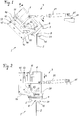
- the in the FIGS. 1 to 6 partially illustrated grinding head 3 includes a cup-shaped grinding wheel 4 with a flat, annular grinding surface 5 on its front side.
- the grinding wheel 4 is coupled to a grinding wheel drive 6, which contains a drive shaft 7, at the end of which the grinding wheel 4 is non-rotatably mounted.
- the glass sheet 2 is in a conventional manner substantially upright in the trimming 1.
- the grinding surface 5 is delivered to a glass panel edge, which in the Figures 1 and 2 runs perpendicular to the drawing plane.
- the grinding wheel 4 and the glass sheet 2 are moved relative to each other in a parallel to the glass sheet 2 and along the glass sheet edge 8 advancing movement perpendicular to the plane of the drawing.
- the relative movement takes place in a conventional manner by moving the grinding head 3 along the glass sheet 2 or by moving the glass sheet 2 in the device 1 by a known horizontal conveyor, not shown, wherein the grinding head 3 can be held stationary.
- the grinding surface 5 carries glass material on the glass sheet edge 8 during the advancing movement.
- the grinding wheel drive 6 is fastened to a motor mount 10.
- the grinding head 3 has a linear electric motor 12 with two stators 13 and two forcer 14.
- Each stator 13 contains a plurality of magnets, not shown, between which a gap 15 extending in the feed direction A is located.
- Each forcer 14 is arranged in one of the gaps 15 and can be moved along the feed direction A by means of a control (not shown) of the trimming device 1.
- the grinding wheel 4 can be displaced by means of the linear motor 12 along the feed direction A running transversely to the grinding surface 5 and delivered to the glass sheet edge 8.
- the linear motor 12 is surrounded by a housing 16 which contains two housing parts 17 and 18 displaceable relative to one another along the feed direction A, of which the housing part 17 is connected to the stator 13 and the housing part 18 to the forcer 14 or the motor mount 10.
- the stator 13 is attached via the housing part 17 to a pivot holder 20.
- the pivot holder 20 has two bearing journals 21, which each in a bearing bush 22 about a pivot axis 23, see FIG. 3 , are rotatably mounted. In the figures, only one of the journals 21 or one of the sockets 22 recognizable.
- the grinding head 3 includes a pivot drive 24, for example in the form of a pneumatic cylinder, which is coupled to the pivot holder 20 and this from the in FIG.
- first pivot position in the pivoting direction B in an in FIG. 2 can rotate shown second pivot position.
- a chamfer is ground to an edge of the glass panel edge 8.
- the front side of the glass sheet edge 8 is ground.
- the grinding head 3 comprises a carrier 26, which is formed from a self-immovable steel structure and for reasons of clarity in FIG. 1 only indicated and not shown in the other figures.
- the above-described components of the grinding head 3 are arranged on the carrier 26.
- the carrier 26 thus forms a support frame of the grinding head 3, to which its components are attached directly or indirectly.
- the bushing 22 and a bearing block 25 of the pivot drive 24 are fixed to the carrier 26 and can not be moved relative to each other.
- a support roller bearing 31 is also attached, with which a support roller 30 is freely rotatably mounted on the carrier 26.
- the support roller 30 supports the glass sheet 2 in the region of its edge 8 and supports the glass sheet 2 in particular with respect to the pressing force of the grinding wheel 4 acting obliquely on the glass sheet edge 8 in the first pivoting position.
- the contact area of the grinding surface 5 with the glass sheet edge 8 and the supporting roller 30 are thus arranged on opposite sides of the glass sheet 2.
- the grinding head 3 and its carrier 26 and the glass sheet 2 are moved relative to each other only in directions parallel to the plane of extension of the glass sheet 2, but not transverse to the glass sheet 2 extending directions.
- a measured perpendicular to the glass panel 2 distance of the journal 21 and the pivot axis 23 is thus not changed. This distance is chosen so that when viewed along the pivot axis 23 seen, so in the view of Figures 1 and 2 , in the first pivot position when grinding the chamfer Edge region of the grinding wheel 4 engages the glass panel edge 8 and that in the second pivot position when grinding the front side, a central region of the grinding wheel 4 engages the glass panel edge 8.
- the abrasion marks generated during trimming in the first grinding position thereby run in as small an angle as possible to the direction of extension of the glass sheet edge 8, while in the second grinding position they extend transversely to the direction of extension of the glass sheet edge 8 in an angle as close as possible to 90 °.
- the axis of rotation of the grinding wheel 4 the end face of the glass panel edge 8 cut.
- the grinding head 3 For guiding the forcer 14 in the gap 15 of the stator 13, the grinding head 3 includes a guide of the motor mount 10, which contains two elongated leaf springs 40 and 45.
- the leaf spring 40 includes two ends 41 and 42 and the leaf spring 45 includes two ends 46 and 47.
- the ends 41 and 46 are firmly clamped to the motor mount 10, respectively.
- the ends 42 and 47 are respectively clamped on the housing part 17 and thus fixed on the housing part 17 on the pivot holder 20.
- the ends 42, 47 are thus held immovably with respect to the carrier 26 and the bearing bush 22 attached thereto. At rest, see FIG. 4 , the two leaf springs 40, 45 are parallel and undeformed.
- the control of the trimming device 1 can now retract the motor mount 10 with the grinding drive 6 and the grinding wheel 4 against the feed direction A by actuating the linear motor 12, see FIG. 5 , or in feed direction A, see FIG. 6 ,
- the leaf springs 40, 45 form during the displacement of the grinding wheel 4 a backlash-free and virtually frictionless guidance.
- the bearing bush 22 still shown, while pivot holder 20 and bearing pin 21 omitted and the housing part 17 have been shown only partially.
- the stroke along the feed direction A is chosen so large that glass sheets 2 can be processed with a thickness of up to 25 mm.
- the linear motor 12 is arranged between the two leaf springs 40 and 45, wherein the forcer 14 between the two leaf springs 40, 45 is fixed to the motor mount 10.
- the leaf springs 40, 45 are in their rest position, see FIG. 4 oriented so that the feed direction A is perpendicular to its plane of extent and perpendicular to Glass panel edge 8 runs.
- the grinding drive 6 may be slightly obliquely mounted on the motor mount 10, so that the axis of rotation of the grinding wheel 4 has an angle of about 1 ° to the feed direction A.
- FIGS. 7 and 8 a variant of a grinding head 3 is shown, which contains two oppositely oriented grinding wheels 4 and 4 '. Like parts are given the same reference numerals as in FIGS FIGS. 1 to 6 provided, wherein the reference numerals, which identify the components belonging to the second grinding wheel 4 ', are each provided with a dash.
- this grinding head can in the first pivoting position, see FIG. 7 , 8 bevels are ground simultaneously on both edges of the glass sheet edge.
- both grinding wheels 4, 4 ' can be used for grinding the end face of the glass sheet edge 8, whereby each of the grinding wheels 4, 4' only has to remove half of the glass material to be removed in total. The feed rate when grinding the front side can be increased.
- Each variant of the grinding wheels 4, 4 ' is a separate linear motor 12, 12' associated with a leaf spring guide.
- FIGS. 9 to 11 schematically, a variant is shown, in which the closer to the grinding wheel 4 arranged leaf spring 40 is longer than the further removed from the grinding wheel 4 leaf spring 45.
- the length of the leaf spring 40 may be, for example, 100 mm to 140 mm, in particular about 120 mm.
- the length of the leaf spring 45 may be, for example 60 mm to 100 mm, in particular about 80 mm.
- the Beklamvorgang with a device 1 described above is carried out according to the invention as follows.
- the Grinding wheel 4 is moved by means of the linear motor 12 along the feed direction A in a desired position.
- the target position is determined from the position of the glass sheet edge 8 and the size of the chamfer to be ground or the amount of glass material to be removed.
- the position of the glass panel edge 8 can determine the control, for example, from a data set made available to it, which describes the glass panel 2 to be processed, in particular its shape, size and thickness.
- the grinding head 3 may comprise, in a manner not shown, a sensing roller connected to the control or a non-contact sensor in order to determine the position of the glass panel edge 8.
- the grinding wheel 4 is moved to the predefined setpoint position before the grinding surface 5 of the moving with the feed movement grinding head 3 reaches the glass panel edge 8. This ensures that the grinding wheel 4 removes exactly the required amount of glass material on the glass sheet edge 8 at the beginning of the trimming.
- the grinding wheel 4 is initially held in its desired position by means of the linear motor 12 and is not moved along the feed direction A.
- the target position may be maintained following a corner of the glass sheet 2 over a range of 10 mm to 150 mm along the glass sheet edge 8.
- the holding of the grinding wheel 4 is terminated in its desired position. Instead, the grinding surface 5 is acted upon by means of the linear motor 12 with a predefined pressure force in the feed direction A and pressed against the glass sheet edge 8.
- the grinding wheel 4 can deviate from the course of the glass sheet edge 8, which can deviate from its ideal shape, for example a straight line, due to manufacturing tolerances of the glass sheet 2. Even if the shape of the glass sheet edge 8, for example, a slight, in itself undesirable, but the quality of the glass sheet 2 otherwise not impairing curvature, is ground by pressing the grinding wheel 4 with the predefined pressure force over the entire length of the glass sheet edge 8 a uniformly large chamfer and safely defused the sharp edge of the glass sheet 2.
- the pressing of the grinding surface 5 is stopped and instead the grinding wheel along the feed direction A in its current position fixed, by the linear motor 12 blocks the compensating movement along the feed direction A.
- the unillustrated control of the trimming device 1 is designed in such a way that the linear motor 12 can be operated by the control in a first operating mode called “holding mode” or in a second operating mode called “pressing mode". In the holding mode, the linear motor 12 blocks the movement of the grinding wheel 4 in the feed direction A.
- the holding mode is used in particular in the region of corners of the glass sheet 2.
- the linear motor 12 acts on the grinding wheel 4 with a defined force in the feed direction A, in particular in a central region between two corners of the glass sheet 2.
Landscapes
- Engineering & Computer Science (AREA)
- Mechanical Engineering (AREA)
- Chemical & Material Sciences (AREA)
- Ceramic Engineering (AREA)
- Inorganic Chemistry (AREA)
- Grinding And Polishing Of Tertiary Curved Surfaces And Surfaces With Complex Shapes (AREA)
Applications Claiming Priority (1)
| Application Number | Priority Date | Filing Date | Title |
|---|---|---|---|
| DE102016110651.8A DE102016110651A1 (de) | 2016-06-09 | 2016-06-09 | Vorrichtung und Verfahren zum Besäumen von Glastafeln |
Publications (2)
| Publication Number | Publication Date |
|---|---|
| EP3254804A2 true EP3254804A2 (fr) | 2017-12-13 |
| EP3254804A3 EP3254804A3 (fr) | 2018-02-14 |
Family
ID=59053974
Family Applications (1)
| Application Number | Title | Priority Date | Filing Date |
|---|---|---|---|
| EP17175134.0A Withdrawn EP3254804A3 (fr) | 2016-06-09 | 2017-06-09 | Dispositif et procédé destinés à rogner des plaques de verre |
Country Status (2)
| Country | Link |
|---|---|
| EP (1) | EP3254804A3 (fr) |
| DE (1) | DE102016110651A1 (fr) |
Cited By (2)
| Publication number | Priority date | Publication date | Assignee | Title |
|---|---|---|---|---|
| WO2022187880A1 (fr) | 2021-03-11 | 2022-09-15 | Mbr Robotics For Glass Gmbh | Dispositif d'usinage de plaques comportant une tête de meulage |
| CN115647982A (zh) * | 2022-12-26 | 2023-01-31 | 沙河市赛孚玻璃制品有限公司 | 一种家具玻璃生产用异形磨边机 |
Families Citing this family (1)
| Publication number | Priority date | Publication date | Assignee | Title |
|---|---|---|---|---|
| DE102022100199A1 (de) | 2022-01-05 | 2023-07-06 | Benteler Maschinenbau Gmbh | Glaskantenbearbeitungsanlage |
Family Cites Families (6)
| Publication number | Priority date | Publication date | Assignee | Title |
|---|---|---|---|---|
| DE3424258C2 (de) * | 1984-06-30 | 1986-12-11 | VEGLA Vereinigte Glaswerke GmbH, 5100 Aachen | Maschine zum Kantenschleifen von Glasscheiben |
| KR950011673B1 (ko) * | 1991-04-24 | 1995-10-07 | 박경 | 사면폭유지와 판유리 모양감지를 겸할수 있는 롤러장치가 부착된 판유리 변형면취기 |
| DE10158646A1 (de) * | 2001-11-22 | 2003-06-12 | Lenhardt Maschinenbau | Vorrichtung zum Besäumen von Glastafeln |
| ITTO20021010A1 (it) * | 2002-11-20 | 2004-05-21 | Biesse Spa | Metodo per il controllo della posizione operativa di una mola utilizzata su di una macchina per la lavorazione di bordi di lastre di vetro, marmo e simili materiali lapidei, e macchina per l'implementazione di tale metodo |
| DE102004049951A1 (de) * | 2004-10-13 | 2006-04-20 | Schneider Gmbh + Co. Kg | Hochdynamische Linsenbearbeitungsmaschine |
| ITTO20040134U1 (it) * | 2004-10-21 | 2005-01-21 | Biesse Spa | Dispositivo per l'esecuzione di smussi con angolazioni variabili sugli spigoli di lastre di vetro, marmo, materiali lapidei o ceramici in genere |
-
2016
- 2016-06-09 DE DE102016110651.8A patent/DE102016110651A1/de not_active Withdrawn
-
2017
- 2017-06-09 EP EP17175134.0A patent/EP3254804A3/fr not_active Withdrawn
Cited By (4)
| Publication number | Priority date | Publication date | Assignee | Title |
|---|---|---|---|---|
| WO2022187880A1 (fr) | 2021-03-11 | 2022-09-15 | Mbr Robotics For Glass Gmbh | Dispositif d'usinage de plaques comportant une tête de meulage |
| AT524760A1 (fr) * | 2021-03-11 | 2022-09-15 | ||
| AT524760B1 (de) * | 2021-03-11 | 2022-11-15 | Vorrichtung zum Bearbeiten von Platten mit einem Schleifkopf | |
| CN115647982A (zh) * | 2022-12-26 | 2023-01-31 | 沙河市赛孚玻璃制品有限公司 | 一种家具玻璃生产用异形磨边机 |
Also Published As
| Publication number | Publication date |
|---|---|
| DE102016110651A1 (de) | 2017-12-14 |
| EP3254804A3 (fr) | 2018-02-14 |
Similar Documents
| Publication | Publication Date | Title |
|---|---|---|
| EP2181816B1 (fr) | Appareil d'usinage | |
| EP2392438B1 (fr) | Dispositif de traitement | |
| EP3581310A1 (fr) | Machine à scier pour coupes d'onglet | |
| DE102010004781B4 (de) | Trenn- und Abisoliereinrichtung für eine Kabelverarbeitungsmaschine | |
| EP3254804A2 (fr) | Dispositif et procédé destinés à rogner des plaques de verre | |
| EP1314513B1 (fr) | Procédé pour l'ébavurage de plaques de verre | |
| DE4113543A1 (de) | Vorrichtung zur bearbeitung der kantenraender von plattenfoermigen werkstuecken | |
| DE102009013740A1 (de) | Arbeitseinheit für die Bearbeitung von Holzplatten oder dergleichen | |
| DE3013410A1 (de) | Fuehrungssystem fuer lineare bewegungen | |
| EP2666583B1 (fr) | Unité mobile d'une machine-outil ainsi que la machine-outil avec une telle unité mobile | |
| DE202008016620U1 (de) | Vorrichtung zum Schleifen, Feinschleifen und/oder Polieren von Werkstücken in optischer Qualität, insbesondere von sphärischen Linsenflächen in der Feinoptik | |
| WO2008014962A1 (fr) | Dispositif de fabrication et/ou d'usinage de panneaux | |
| DE102013100751A1 (de) | Vorrichtung und Verfahren zum Schleifen mindestens eines an einer Messertrommel angeordneten und umlaufend angetriebenen Trennmessers | |
| DE2219181C2 (de) | Brennschneidmaschine. Asm: Messer Griesbeim GmbH, 6000 Frankfurt | |
| DE102013006606B4 (de) | Werkzeugwechsler | |
| EP0310898A1 (fr) | Dispositif pour le laminage de filets ou de profilés similaires | |
| EP0483499A2 (fr) | Machine pour l'usinage des extrémités de châssis de fenêtres | |
| DE3428714C2 (fr) | ||
| DE69103367T2 (de) | Maschine zur Herstellung von geschliffenen Schrauben ausgehend von Stäben. | |
| DE3109427C2 (fr) | ||
| DE69102772T2 (de) | Vorrichtung zum bearbeiten und zur oberflächenbehandlung von elastischen materialien. | |
| DE2052981A1 (de) | Werkstückträger fur eine spitzenlose Rundschleifmaschine | |
| DE2251750C3 (de) | Vorrichtung zum Markieren von auf einer Rollenbahn bewegten Profilteilen | |
| EP1663564A1 (fr) | Pince porte-electrode | |
| DE29501631U1 (de) | Zuführ- und/oder Abführvorrichtung für Drehteile, die spitzenlos in einer Schleifmaschine an ihrer Außenseite geschliffen werden |
Legal Events
| Date | Code | Title | Description |
|---|---|---|---|
| PUAI | Public reference made under article 153(3) epc to a published international application that has entered the european phase |
Free format text: ORIGINAL CODE: 0009012 |
|
| STAA | Information on the status of an ep patent application or granted ep patent |
Free format text: STATUS: THE APPLICATION HAS BEEN PUBLISHED |
|
| AK | Designated contracting states |
Kind code of ref document: A2 Designated state(s): AL AT BE BG CH CY CZ DE DK EE ES FI FR GB GR HR HU IE IS IT LI LT LU LV MC MK MT NL NO PL PT RO RS SE SI SK SM TR |
|
| AX | Request for extension of the european patent |
Extension state: BA ME |
|
| PUAL | Search report despatched |
Free format text: ORIGINAL CODE: 0009013 |
|
| AK | Designated contracting states |
Kind code of ref document: A3 Designated state(s): AL AT BE BG CH CY CZ DE DK EE ES FI FR GB GR HR HU IE IS IT LI LT LU LV MC MK MT NL NO PL PT RO RS SE SI SK SM TR |
|
| AX | Request for extension of the european patent |
Extension state: BA ME |
|
| RIC1 | Information provided on ipc code assigned before grant |
Ipc: B24B 9/10 20060101AFI20180111BHEP Ipc: B24B 41/053 20060101ALI20180111BHEP |
|
| STAA | Information on the status of an ep patent application or granted ep patent |
Free format text: STATUS: THE APPLICATION IS DEEMED TO BE WITHDRAWN |
|
| 18D | Application deemed to be withdrawn |
Effective date: 20180815 |