EP3254017B1 - Reflektorvorrichtung für ein lichtmodul mit elektromagnetischer abschirmung - Google Patents
Reflektorvorrichtung für ein lichtmodul mit elektromagnetischer abschirmung Download PDFInfo
- Publication number
- EP3254017B1 EP3254017B1 EP16703510.4A EP16703510A EP3254017B1 EP 3254017 B1 EP3254017 B1 EP 3254017B1 EP 16703510 A EP16703510 A EP 16703510A EP 3254017 B1 EP3254017 B1 EP 3254017B1
- Authority
- EP
- European Patent Office
- Prior art keywords
- housing
- lighting module
- module according
- light
- face
- Prior art date
- Legal status (The legal status is an assumption and is not a legal conclusion. Google has not performed a legal analysis and makes no representation as to the accuracy of the status listed.)
- Active
Links
Images

Classifications
-
- F—MECHANICAL ENGINEERING; LIGHTING; HEATING; WEAPONS; BLASTING
- F21—LIGHTING
- F21S—NON-PORTABLE LIGHTING DEVICES; SYSTEMS THEREOF; VEHICLE LIGHTING DEVICES SPECIALLY ADAPTED FOR VEHICLE EXTERIORS
- F21S41/00—Illuminating devices specially adapted for vehicle exteriors, e.g. headlamps
- F21S41/30—Illuminating devices specially adapted for vehicle exteriors, e.g. headlamps characterised by reflectors
- F21S41/37—Illuminating devices specially adapted for vehicle exteriors, e.g. headlamps characterised by reflectors characterised by their material, surface treatment or coatings
-
- F—MECHANICAL ENGINEERING; LIGHTING; HEATING; WEAPONS; BLASTING
- F21—LIGHTING
- F21S—NON-PORTABLE LIGHTING DEVICES; SYSTEMS THEREOF; VEHICLE LIGHTING DEVICES SPECIALLY ADAPTED FOR VEHICLE EXTERIORS
- F21S41/00—Illuminating devices specially adapted for vehicle exteriors, e.g. headlamps
- F21S41/10—Illuminating devices specially adapted for vehicle exteriors, e.g. headlamps characterised by the light source
- F21S41/14—Illuminating devices specially adapted for vehicle exteriors, e.g. headlamps characterised by the light source characterised by the type of light source
- F21S41/141—Light emitting diodes [LED]
- F21S41/147—Light emitting diodes [LED] the main emission direction of the LED being angled to the optical axis of the illuminating device
- F21S41/148—Light emitting diodes [LED] the main emission direction of the LED being angled to the optical axis of the illuminating device the main emission direction of the LED being perpendicular to the optical axis
-
- F—MECHANICAL ENGINEERING; LIGHTING; HEATING; WEAPONS; BLASTING
- F21—LIGHTING
- F21S—NON-PORTABLE LIGHTING DEVICES; SYSTEMS THEREOF; VEHICLE LIGHTING DEVICES SPECIALLY ADAPTED FOR VEHICLE EXTERIORS
- F21S41/00—Illuminating devices specially adapted for vehicle exteriors, e.g. headlamps
- F21S41/10—Illuminating devices specially adapted for vehicle exteriors, e.g. headlamps characterised by the light source
- F21S41/19—Attachment of light sources or lamp holders
- F21S41/192—Details of lamp holders, terminals or connectors
-
- F—MECHANICAL ENGINEERING; LIGHTING; HEATING; WEAPONS; BLASTING
- F21—LIGHTING
- F21S—NON-PORTABLE LIGHTING DEVICES; SYSTEMS THEREOF; VEHICLE LIGHTING DEVICES SPECIALLY ADAPTED FOR VEHICLE EXTERIORS
- F21S41/00—Illuminating devices specially adapted for vehicle exteriors, e.g. headlamps
- F21S41/20—Illuminating devices specially adapted for vehicle exteriors, e.g. headlamps characterised by refractors, transparent cover plates, light guides or filters
- F21S41/25—Projection lenses
- F21S41/275—Lens surfaces, e.g. coatings or surface structures
-
- F—MECHANICAL ENGINEERING; LIGHTING; HEATING; WEAPONS; BLASTING
- F21—LIGHTING
- F21S—NON-PORTABLE LIGHTING DEVICES; SYSTEMS THEREOF; VEHICLE LIGHTING DEVICES SPECIALLY ADAPTED FOR VEHICLE EXTERIORS
- F21S43/00—Signalling devices specially adapted for vehicle exteriors, e.g. brake lamps, direction indicator lights or reversing lights
- F21S43/10—Signalling devices specially adapted for vehicle exteriors, e.g. brake lamps, direction indicator lights or reversing lights characterised by the light source
- F21S43/13—Signalling devices specially adapted for vehicle exteriors, e.g. brake lamps, direction indicator lights or reversing lights characterised by the light source characterised by the type of light source
- F21S43/14—Light emitting diodes [LED]
-
- F—MECHANICAL ENGINEERING; LIGHTING; HEATING; WEAPONS; BLASTING
- F21—LIGHTING
- F21S—NON-PORTABLE LIGHTING DEVICES; SYSTEMS THEREOF; VEHICLE LIGHTING DEVICES SPECIALLY ADAPTED FOR VEHICLE EXTERIORS
- F21S45/00—Arrangements within vehicle lighting devices specially adapted for vehicle exteriors, for purposes other than emission or distribution of light
-
- F—MECHANICAL ENGINEERING; LIGHTING; HEATING; WEAPONS; BLASTING
- F21—LIGHTING
- F21V—FUNCTIONAL FEATURES OR DETAILS OF LIGHTING DEVICES OR SYSTEMS THEREOF; STRUCTURAL COMBINATIONS OF LIGHTING DEVICES WITH OTHER ARTICLES, NOT OTHERWISE PROVIDED FOR
- F21V15/00—Protecting lighting devices from damage
- F21V15/01—Housings, e.g. material or assembling of housing parts
-
- H—ELECTRICITY
- H05—ELECTRIC TECHNIQUES NOT OTHERWISE PROVIDED FOR
- H05B—ELECTRIC HEATING; ELECTRIC LIGHT SOURCES NOT OTHERWISE PROVIDED FOR; CIRCUIT ARRANGEMENTS FOR ELECTRIC LIGHT SOURCES, IN GENERAL
- H05B45/00—Circuit arrangements for operating light-emitting diodes [LED]
-
- F—MECHANICAL ENGINEERING; LIGHTING; HEATING; WEAPONS; BLASTING
- F21—LIGHTING
- F21S—NON-PORTABLE LIGHTING DEVICES; SYSTEMS THEREOF; VEHICLE LIGHTING DEVICES SPECIALLY ADAPTED FOR VEHICLE EXTERIORS
- F21S41/00—Illuminating devices specially adapted for vehicle exteriors, e.g. headlamps
- F21S41/10—Illuminating devices specially adapted for vehicle exteriors, e.g. headlamps characterised by the light source
- F21S41/14—Illuminating devices specially adapted for vehicle exteriors, e.g. headlamps characterised by the light source characterised by the type of light source
- F21S41/141—Light emitting diodes [LED]
- F21S41/147—Light emitting diodes [LED] the main emission direction of the LED being angled to the optical axis of the illuminating device
-
- F—MECHANICAL ENGINEERING; LIGHTING; HEATING; WEAPONS; BLASTING
- F21—LIGHTING
- F21S—NON-PORTABLE LIGHTING DEVICES; SYSTEMS THEREOF; VEHICLE LIGHTING DEVICES SPECIALLY ADAPTED FOR VEHICLE EXTERIORS
- F21S43/00—Signalling devices specially adapted for vehicle exteriors, e.g. brake lamps, direction indicator lights or reversing lights
- F21S43/20—Signalling devices specially adapted for vehicle exteriors, e.g. brake lamps, direction indicator lights or reversing lights characterised by refractors, transparent cover plates, light guides or filters
-
- F—MECHANICAL ENGINEERING; LIGHTING; HEATING; WEAPONS; BLASTING
- F21—LIGHTING
- F21S—NON-PORTABLE LIGHTING DEVICES; SYSTEMS THEREOF; VEHICLE LIGHTING DEVICES SPECIALLY ADAPTED FOR VEHICLE EXTERIORS
- F21S45/00—Arrangements within vehicle lighting devices specially adapted for vehicle exteriors, for purposes other than emission or distribution of light
- F21S45/40—Cooling of lighting devices
- F21S45/47—Passive cooling, e.g. using fins, thermal conductive elements or openings
- F21S45/48—Passive cooling, e.g. using fins, thermal conductive elements or openings with means for conducting heat from the inside to the outside of the lighting devices, e.g. with fins on the outer surface of the lighting device
-
- F—MECHANICAL ENGINEERING; LIGHTING; HEATING; WEAPONS; BLASTING
- F21—LIGHTING
- F21Y—INDEXING SCHEME ASSOCIATED WITH SUBCLASSES F21K, F21L, F21S and F21V, RELATING TO THE FORM OR THE KIND OF THE LIGHT SOURCES OR OF THE COLOUR OF THE LIGHT EMITTED
- F21Y2115/00—Light-generating elements of semiconductor light sources
- F21Y2115/10—Light-emitting diodes [LED]
Definitions
- the present invention relates to a reflector, and more particularly relates to the application of such a device in a light module comprising at least one light emitting diode whose emitted light is reflected by the inner faces of the reflector.
- the provisions of the reflector make it possible to attenuate the effects of the electromagnetic waves emitted by the diode or diodes or their supply circuit.
- Thermal cooling means are conventionally associated with this type of light modules equipped with a light-emitting diode, LED, since this diode is generally carried by a printed circuit board also carrying electronic components for carrying out power and control. of the diode.
- a control circuit of the LED supply generally comprises a DC / DC converter adapted to convert an input voltage, supplied by a vehicle power source such as the battery, into a charge voltage capable of driving the LEDs. .
- the LEDs must be cooled for their punctual operation and their behavior over time.
- Some of these electronic components for example a DC / DC converter, and on a smaller scale also the electroluminescent diodes supplied, generate electromagnetic disturbances, and it is necessary to prevent their diffusion outside the module to prevent them from interfering other electronic equipment present in the vehicle.
- the present invention is in this context, and aims to provide means capable of mitigating electromagnetic disturbances that do not have the disadvantages mentioned above, and which are particularly simple to implement and adaptable to different configurations of modules.
- the subject of the invention is a light module according to claim 1.
- the metallized portion of the internal faces of the casing may be arranged so that light emitted by the light source (s) and reflected by this metallized part forms a light beam producing a predetermined photometric function, such as a function fog.
- the receiving means may comprise a recess in the outer face of said wall of the housing, the bottom of the recess comprising said opening.
- the receiving means may comprise one or more indexing studs for aligning the support comprising the light sources with respect to the reflector housing, so that the LEDs are oriented such that their emitted light can be propagated through the opening towards the inside of the case, where it is reflected.
- All external faces of the housing can preferably be metallized.
- the metallization of the outer face may comprise an aluminum layer.
- the invention relates to a light module for lighting and / or signaling of a motor vehicle.
- the light module comprises at least one light source powered by a control circuit of the power supply and disposed on a support, and a reflector device.
- the receiving means of the housing are adapted to accommodate said support so as to allow the light emitted by the light sources to propagate through said opening, and the contact area is connected to ground.
- the housing of the reflector device forms the housing of the light module.
- said at least a portion of the metallized internal faces of the module housing form a reflector.
- the module may include a transparent closure glass for passing light reflected by the reflector device, the housing having a front opening closed by said closure glass.
- the support may preferably comprise a plate which has on its periphery notches adapted to cooperate with the indexing studs arranged on the housing.
- the plate may preferably also have in its center bores adapted to cooperate with indexing barrels arranged this time on the inner face of a cover adapted to cover the support.
- the plate may further comprise lights arranged regularly near a longitudinal front edge, adapted to cooperate with tongues carried by a lateral closure element of the support.
- the support may advantageously be a printed circuit board (PCB), the light sources being disposed on a first face of the card which is oriented towards the outer face of the housing wall of the reflector device.
- PCB printed circuit board
- the support may be a flexible printed circuit board (FPCB).
- FPCB flexible printed circuit board
- the printed circuit board may preferably comprise on its second face at least one electronic component for controlling and feeding the light sources.
- the first face of the circuit board may comprise an electrically conductive spring whose end is fixed by welding to the support and connected to ground. The second end of the spring comes into contact with the contact zone of the housing when the card is housed in the receiving means.
- the module may advantageously comprise a radiator element arranged to allow the evacuation of the heat produced by the light sources or the control circuit of the power supply.
- the light sources can preferably be arranged on the radiator element.
- the control and power supply circuit can advantageously be connected to the light sources by electrical connections by wire-bonding, the circuit in question being offset with respect to the location of the light sources.
- the remote circuit may also be arranged on the radiator element.
- the zone of contact of the housing may preferably be electrically connected to the radiator element, which is connected to ground.
- the radiator element is made of an electrically conductive material, for example metal.
- the contact zone of the housing can be electrically connected to an element of the control circuit, which is connected to ground.
- the light sources may advantageously be light-emitting diodes, LEDs, or alternatively laser diodes.
- the module may also preferably include a cover adapted to cover the support which is housed in the receiving means of the housing.
- the housing comprises a recess on its inner face.
- the recess of the inner face may preferably comprise two zones separated substantially transversely by confinement walls. A first zone may be delimited by these walls and by a circular border and a second zone forming the confinement zone may preferably be delimited by these walls and by a border formed by straight line segments.
- the inner face of the cover may preferably comprise, inside these walls defining the housing, a central barrel, with a channel around the periphery to prevent the thermal tab overflows the assembly of the circuit board on the hood .
- a thermal lug can in fact preferably be placed on the top of the barrel adapted to be in contact with the printed circuit board during assembly, to facilitate transmission of the heat emitted by the diode to the hood and its thermal cooling means.
- the inner face of the hood may also carry two indexing barrels longitudinally disposed on either side of the central barrel, and indexing means complementary to those formed on the housing for gripping the printed circuit board.
- the side walls of the hood unlike the transverse wall, do not have a flat surface at their free end, but a wall disposed on the side opposite the confinement zone forming a stop for the establishment of the card printed circuit boards on the side walls.
- the sidewalls may preferably be truncated at the end of a baffle, so that they do not meet each other, and thus leave an opening at a longitudinal end before the confinement zone, between the side walls, at the edge formed by segments of right.
- a front and rear longitudinal end being defined according to the implantation in the motor vehicle.
- the module also comprises a lateral closure element of the support, adapted to cooperate with lights arranged on an edge of said support plate.
- the closure element may preferably be made of a sheet metal part advantageously made of stainless steel.
- the height of the closure element that is to say the distance between the first carrying edge of the fastening means and the second plane edge, is slightly less than the distance between the support plane of the printed circuit board. and the bottom of the house at the level of the channel. In this way, an air passage is left between the bottom of the housing and the insert element acting as a closure part of the opening of the confinement zone.
- the closure member may preferably further include bosses formed projecting from the plane of the workpiece in the vicinity of an edge. These bosses are intended to ensure the grounding of the part, caused to stop the electromagnetic waves generated in the containment zone on the hood.
- the reflector element of a light module also becomes a shield element against the electromagnetic waves emitted either by the electronic components that form the light source power supply circuit of the module, either by the sources themselves.
- the embodiment is particularly advantageous since it may be limited, according to a preferred embodiment, to the addition of a metallized contact zone on the rear face of the reflector, the rear face being the face which has no optical activity of light reflection during normal operation. This contact zone can be connected to ground when mounting the light module in a predetermined and robust manner.
- the reflector according to the invention can be used with numerous configurations of power supply circuits, heat radiators or types of light sources.
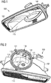
- a reflector device 100 is shown in the illustration of the figure 1 . It comprises a housing 102 made of plastic.
- the casing is in known manner formed by molding a synthetic material or by thermoforming, depending on the material used.
- the internal faces 110 of such a housing are metallized and shaped so as to reflect the light incident therein in predefined directions and which depend on the intended use of the light module. whose reflector may be part of it.
- the reflected light can then be directed by a non-illustrated light guide coupled to the open face of the housing.
- An opening 140 communicates the interior of the housing with its rear face.
- the outer face 120 of one of the walls of the housing 102 comprises receiving means 130 which can house a light device.
- a light device This is for example a support, such as a printed circuit, comprising light emitting diodes, LEDs.
- Indexing studs 121 are provided for aligning the light device relative to the housing, so that the LEDs are oriented such that their emitted light can propagate through the opening 140 to the inside of the housing, where it is thoughtful.
- an LED power supply circuit is provided on the printed circuit board that includes the LEDs.
- the circuit comprises a converter that makes it possible to convert an input voltage supplied by a battery of a vehicle into a charge voltage capable of supplying the LEDs.
- the supply circuit and provided on the opposite side of the PCB of the printed circuit, so as to reduce the electromagnetic disturbances that it produces in the direction of light emission.
- the receiving means 130 comprise a recess formed in the outer face 120 of the housing.
- the recess shown to a circular shape.
- the bottom of the recess includes the opening 140 which allows the emitted light to enter the interior of the reflector. Electromagnetic waves can also propagate through this opening.
- the receiving means may in other embodiments be formed by means that allow to hang an LED support to the face 120, without requiring the presence of the recess.
- a contact zone 134 for connecting the rear of the housing to ground is provided on the rear face 120, and in particular at the receiving means 130.
- This is a metallized area for example aluminum by metallization processes known per se.
- Area 134 is illustrated as a generally circular portion of the bottom of the recess of the receiving means. Alternatively, the zone 134 may cover the entire bottom of the recess or even the entire face 120 of the housing.
- the use of the housing according to the invention in a light module for lighting and / or signaling of a motor vehicle makes it possible to connect the contact zone 134 by direct contact with the ground potential present on the printed circuit which is accommodated by the receiving means 130.
- the electrical connection of the contact zone can also be done by an electrically conductive spring, one end of which is welded to the printed circuit housed in the receiving means 130 and connected to the ground potential.
- the spring is sufficiently long, and its location is chosen so that its free end comes to contact the contact zone 134 when the printed circuit is mounted and fixed to the housing 102.
- the spring is welded to the contact zone 134 of the housing, and its free end comes to contact an area connected to the ground on the printed circuit during assembly.
- the zone 134 is electrically connected with a radiator element which allows the evacuation of the heat produced by the light sources and / or the supply circuit during their operation.
- the radiator element is connected to the ground potential.
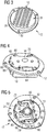
- Thermal exchange means such as a radiator are formed on an outer face of a hood 12 illustrated in FIG. figure 3 disposed in the receiving means 130 formed in the cover wall of the housing or housing 102.
- the hood is illustrated in figure 3 seen from above, that is to say with the outer face 28, carrier of the heat exchange ribs, which is visible.
- the cover has on this outer face a central thickening 30, adapted to allow a consequent recess of the inner face 31 opposite for the housing of the printed circuit board.
- the cover further comprises fixing bores 32 to the housing 102, so as to ensure the attachment of the cover to the housing by means of screwing means not shown.
- the printed circuit board 33 consists of a plate on which is welded the light emitting diode (s) as well as electronic components for controlling the operation of the diode, according to control instructions received by a module associated with the diode.
- the printed circuit board 33 is attached to the inner face 31 of the cover, it is understood that the diode is soldered on the outer face of the card, opposite the cover 12 in order to emit light rays towards the opening 140 provided in the housing, while the electronic components are welded to the inner face of the card, facing the hood 12.
- the circuit board 33 comprises on the face which houses the light sources at least one range 34 representing the ground potential, which is able to contact the contact zone 134 of the housing when the light module is assembled as described. .
- the electronic components are welded to the plate, and these components can advantageously be arranged on the plate according to their potential for generating electromagnetic waves. It will thus be possible to place the large suppliers of electromagnetic disturbances, such as for example a DC / DC voltage converter, in a specific area of the plate to ensure their placement in the wave confinement cage as it is going to be. be described below. Electronic components that do not create or have little electromagnetic interference can be arranged on the plate.
- the plate has on its periphery notches 36 adapted to cooperate with the indexing studs 121 arranged on the housing 102, and it has at its center bores 38 adapted to cooperate with indexing barrels arranged this time on the inner face of the hood, as will be described below.
- the plate also has lights 40 arranged regularly near a longitudinal edge 42 before the printed circuit board, adapted to cooperate with tabs carried by the insert element 80. Here, four of these lights are provided.
- the plate has at each longitudinal end rounded edges 44 and, from one longitudinal end to the other, two parallel lateral edges 46 delimited longitudinally by transverse edges 48 which extend perpendicularly these lateral edges towards the outside the plate.
- the inner face 31 of the cover is recessed to form a housing and has projecting elements adapted to form a confining cage electromagnetic waves generated by the electronic components.
- the recess of the inner face comprises two zones separated substantially transversely by containment walls.
- a first zone 50 is delimited by these walls and by a circular border 51 and a second zone, forming the confinement zone 52, is delimited by these walls and by a border 53 formed by straight segments.
- the inner face 31 of the hood comprises, inside these walls delimiting the housing, a central barrel 54, with a channel 56 around the periphery to prevent that the thermal lug overflows the mounting of the circuit board on the hood.
- a thermal lug is indeed placed on the top of the barrel adapted to be in contact with the printed circuit board assembly, to facilitate the transmission of heat emitted by the diode to the hood and its thermal cooling means.
- the inner face 31 of the hood also carries two indexing rods 58 longitudinally disposed on either side of the central barrel 54, and indexing means 60 complementary to those formed on the housing for gripping the printed circuit board 33.
- the inner face of the cover has walls that project from the bottom wall of the housing to delimit the first zone 50 and the confinement zone 52.
- a first transverse wall 62 extends substantially across the housing. Its free end opposite the hood has a flat surface, to serve as a support for the printed circuit board.
- the transverse wall is extended perpendicularly by lateral walls 64 which are connected respectively to one of the lateral ends of the transverse wall.
- These side walls have a main part 66, which extends longitudinally in the continuity of the transverse wall, and a baffle formed of an intermediate wall 68 which extends transversely to the main part and of a substantially parallel end wall 70 at the main part.
- the side walls 64 unlike the transverse wall 62, do not have a flat surface at their free end, but a wall 72 disposed on the side opposite the zone of containment and which forms a stop to the establishment of the printed circuit board on the side walls.
- the card rests on the flat face of the transverse wall so that it extends on either side of this transverse wall, while it rests on the side walls with the walls surrounding it.
- the sidewalls 64 are truncated at the end of the baffle, so that they do not meet each other, and thus leave an opening 74 at a forward longitudinal end of the baffle zone. confinement, between the side walls, at the edge 53 formed by straight segments.
- a front and rear longitudinal end is defined according to the implantation in the vehicle.
- the orientation chosen here is particularly interesting in that the opening is directed away from the passenger compartment, so that any leakage of electromagnetic waves would be without consequences. It will be understood, however, that the orientation of the assembly could change without departing from the context of the invention.
- the bottom wall of the housing is a flat surface, on one as on the other of the zones delimited by the edges and the confinement walls.
- an additional wall 76 extends projecting from the bottom wall, facing the edge 53 formed by the straight segments.
- the additional wall 76 has a lower height than the edge 53 and is also formed by straight segments to extend parallel to this edge. This forms a channel 78 between the edge of the housing and the additional wall, wherein the insert element 80 is able to come to take place.
- the depth of the containment cage formed in the housing on one side of the confinement walls may be greater than that of the housing on the other side of the confinement walls. It will thus be possible to house larger electronic components.
- the confinement cage 52 of the electromagnetic waves produced in the light module according to the invention is specific in that it has an opening 74 in a first axial direction.
- a mode of use in which a insert element 80, disposed between the cover 12 and the printed circuit board 33, acts as a closure piece capable of blocking this opening.
- the axial opening is not blocked by an insert or the insert is replaced by a wall integral with the hood cavity.
- the insert element acting as a closure piece is made of a metallic material. This makes it possible to reinforce the attenuation of the electromagnetic disturbances generated by the said at least one electronic component.
- the attached element takes the form of a folded sheet metal part 80, visible in particular on the figure 7 .
- the piece is folded to take the form of successive straight portions, complementary to that of the channel 78 formed at the axial end of the confinement zone 52.
- a first edge 82 carries fastening means and a second edge 84 is straight.
- the insert is secured to the plate.
- the fastening means take the form of tabs 86, each tab projecting from the first edge 82, in the plane of the right portion of the piece which it extends.
- the folded sheet metal part furthermore includes bosses 88 formed projecting from the plane of the part, in the vicinity of the second right edge 84. These bosses are intended to ensure the grounding of the folded sheet metal part, brought to stop the waves. electromagnetic generated in the containment zone, on the hood.
- the sheet metal part is advantageously made of stainless steel, interesting here to have good elasticity of the part at the bosses to facilitate the contact of the part with the hood at the channel, and for there to be no oxidation of the sheet metal part.
- the height of the insert, acting as a closing piece that is to say the distance between the first bearing edge of the fastening means and the second plane edge, is slightly less than the distance between the support plane of the printed circuit board and the bottom of the housing at the level of the channel. In this way, we leave a passage of air between the bottom of the housing and the insert element acting as closing part of the opening of the confinement zone.
Claims (12)
- Lichtmodul für die Beleuchtung und/oder Signalgebung eines Kraftfahrzeugs, welches wenigstens eine Lichtquelle, die von einer Schaltung zur Ansteuerung der Stromversorgung gespeist wird und auf einer Halterung angeordnet ist, und eine Reflektorvorrichtung (100) umfasst, wobei die Reflektorvorrichtung (100) ein Gehäuse (102) aus Kunststoff umfasst, bei dem wenigstens ein Teil seiner Innenflächen (110) metallisiert ist, um empfangenes Licht zu reflektieren, wobei das Gehäuse auf einer Außenfläche (120) einer seiner Wände Aufnahmemittel (130) umfasst, welche die Aufnahme einer Halterung ermöglichen, die wenigstens eine Lichtquelle umfasst, wobei die Wand eine Öffnung (140) umfasst, die ins Innere des Gehäuses führt und die ermöglicht, dass sich das von der oder den Lichtquellen ausgesendete Licht zum Inneren des Gehäuses hin ausbreitet, wobei wenigstens ein Teil der Aufnahmemittel (130) auf der Außenfläche (120) des Gehäuses (102) metallisiert ist, so dass ein Kontaktbereich (134) definiert wird, welcher die Herstellung eines elektrischen Kontakts mit dem metallisierten Teil ermöglicht,
wobei die Aufnahmemittel (130) des Gehäuses (102) geeignet sind, die Halterung aufzunehmen, so dass ermöglicht wird, dass sich das von den Lichtquellen ausgesendete Licht durch die Öffnung (140) hindurch ausbreitet, und wobei der Kontaktbereich (134) mit Masse verbunden ist, dadurch gekennzeichnet, dass das Gehäuse der Reflektorvorrichtung das Gehäuse des Lichtmoduls bildet. - Lichtmodul nach Anspruch 1, dadurch gekennzeichnet, dass die Aufnahmemittel (130) eine Aussparung in der Außenfläche (120) der Wand des Gehäuses umfassen, wobei der Boden (132) der Aussparung die Öffnung (140) umfasst.
- Lichtmodul nach einem der Ansprüche 1 oder 2, dadurch gekennzeichnet, dass alle Außenflächen des Gehäuses (102) metallisiert sind.
- Lichtmodul nach einem der Ansprüche 1 bis 3, dadurch gekennzeichnet, dass die Metallisierung der Außenfläche (120) eine Aluminiumschicht umfasst.
- Lichtmodul nach einem der Ansprüche 1 bis 4, dadurch gekennzeichnet, dass die Halterung eine Leiterplatte ist, wobei die Lichtquellen auf einer ersten Seite der Platte angeordnet sind, welche der Außenfläche (120) der Wand des Gehäuses (102) der Reflektorvorrichtung (100) zugewandt ist.
- Lichtmodul nach Anspruch 5, dadurch gekennzeichnet, dass die Leiterplatte auf ihrer zweiten Seite wenigstens eine elektronische Komponente zur Ansteuerung und Stromversorgung der Lichtquellen umfasst.
- Lichtmodul nach einem der Ansprüche 1 bis 6, dadurch gekennzeichnet, dass die erste Seite der Leiterplatte eine elektrisch leitende Feder umfasst, deren eines Ende durch Schweißen an der Halterung befestigt und mit Masse verbunden ist, wobei das zweite Ende mit dem Kontaktbereich (134) des Gehäuses (102) in Kontakt kommt, wenn die Platte in dem Aufnahmemittel (130) aufgenommen ist.
- Lichtmodul nach einem der Ansprüche 1 bis 4, dadurch gekennzeichnet, dass das Modul außerdem ein Strahlerelement umfasst, das derart angeordnet ist, dass es die Ableitung der Wärme ermöglicht, die von den Lichtquellen oder der Schaltung zur Ansteuerung der Stromversorgung erzeugt wird.
- Lichtmodul nach Anspruch 8, dadurch gekennzeichnet, dass die Lichtquellen auf dem Strahlerelement angeordnet sind.
- Lichtmodul nach Anspruch 8 oder 9, dadurch gekennzeichnet, dass der Kontaktbereich (134) elektrisch mit dem Strahlerelement verbunden ist, welches mit Masse verbunden ist.
- Lichtmodul nach einem der Ansprüche 1 bis 7, dadurch gekennzeichnet, dass der Kontaktbereich (134) elektrisch mit einem Element der Ansteuerschaltung verbunden ist, welche mit Masse verbunden ist.
- Lichtmodul nach einem der Ansprüche 1 bis 11, dadurch gekennzeichnet, dass die Lichtquellen Leuchtdioden, LEDs, sind.
Applications Claiming Priority (2)
| Application Number | Priority Date | Filing Date | Title |
|---|---|---|---|
| FR1550971A FR3032516B1 (fr) | 2015-02-06 | 2015-02-06 | Dispositif reflecteur d'un module lumineux avec blindage electromagnetique |
| PCT/EP2016/052334 WO2016124664A1 (fr) | 2015-02-06 | 2016-02-04 | Dispositif réflecteur d'un module lumineux avec blindage électromagnétique |
Publications (2)
| Publication Number | Publication Date |
|---|---|
| EP3254017A1 EP3254017A1 (de) | 2017-12-13 |
| EP3254017B1 true EP3254017B1 (de) | 2018-12-19 |
Family
ID=52824495
Family Applications (1)
| Application Number | Title | Priority Date | Filing Date |
|---|---|---|---|
| EP16703510.4A Active EP3254017B1 (de) | 2015-02-06 | 2016-02-04 | Reflektorvorrichtung für ein lichtmodul mit elektromagnetischer abschirmung |
Country Status (5)
| Country | Link |
|---|---|
| US (1) | US11193644B2 (de) |
| EP (1) | EP3254017B1 (de) |
| CN (1) | CN107429888B (de) |
| FR (1) | FR3032516B1 (de) |
| WO (1) | WO2016124664A1 (de) |
Families Citing this family (3)
| Publication number | Priority date | Publication date | Assignee | Title |
|---|---|---|---|---|
| FR3068313B1 (fr) * | 2017-06-29 | 2020-10-02 | Valeo Vision Belgique | Dispositif d'eclairage pour vehicule automobile muni d'un faisceau electrique guide |
| CN110043830B (zh) * | 2019-04-11 | 2021-07-27 | 广东美的厨房电器制造有限公司 | 照明装置及微波炉 |
| EP4207956A1 (de) | 2021-12-28 | 2023-07-05 | ZKW Group GmbH | Fahrzeugscheinwerfermodul |
Family Cites Families (35)
| Publication number | Priority date | Publication date | Assignee | Title |
|---|---|---|---|---|
| FR2484058A1 (fr) | 1980-06-06 | 1981-12-11 | Seima | Bloc optique d'eclairage, notamment pour projecteur de vehicule automobile |
| US5343370A (en) * | 1990-10-23 | 1994-08-30 | Koito Manufacturing Co., Ltd. | Motor vehicle headlamp |
| US6066921A (en) * | 1995-02-28 | 2000-05-23 | Matsushita Electric Works, Ltd. | Discharge lamp lighting device |
| JP3195215B2 (ja) * | 1995-12-28 | 2001-08-06 | 株式会社小糸製作所 | 自動車用ヘッドランプ |
| JP3159078B2 (ja) * | 1996-08-30 | 2001-04-23 | 株式会社デンソー | 高圧放電灯装置 |
| FR2769072B1 (fr) * | 1997-09-26 | 1999-12-24 | Valeo Vision | Projecteur de vehicule automobile equipe d'une lampe a decharge et de moyens perfectionnes de blindage electromagnetique |
| JP3854421B2 (ja) * | 1999-02-23 | 2006-12-06 | 株式会社小糸製作所 | 放電バルブを有する車両用灯具 |
| FR2796647B1 (fr) * | 1999-07-21 | 2002-05-03 | Valeo Vision | Procede de traitement de surface de pieces optiques pour vehicule automobile, en matiere plastique |
| JP3836657B2 (ja) * | 2000-03-31 | 2006-10-25 | 株式会社小糸製作所 | ライン式膜形成方法 |
| DE10193456T1 (de) * | 2000-08-18 | 2002-10-24 | Mitsubishi Electric Corp | Abgeschirmter Draht, Verfahren zur Herstellung eines abgeschirmten Drahtes und Leuchtvorrichtung für eine Entladungslampe, welche den abgeschirmten Draht verwendet |
| CN2452818Y (zh) | 2000-12-14 | 2001-10-10 | 庄国庆 | 复合结构机动车车灯反光镜 |
| US7300173B2 (en) * | 2004-04-08 | 2007-11-27 | Technology Assessment Group, Inc. | Replacement illumination device for a miniature flashlight bulb |
| FR2865884B1 (fr) * | 2004-02-02 | 2006-06-16 | Valeo Vision | Dispositif de regulation du flux des lampes halogenes pour dispositif d'eclairage et/ou de signalisation |
| ATE441204T1 (de) | 2004-10-04 | 2009-09-15 | Koninkl Philips Electronics Nv | Lampensockel mit verbesserter wärmeleitung |
| DE102007037822A1 (de) * | 2007-08-10 | 2009-02-12 | Osram Gesellschaft mit beschränkter Haftung | Beleuchtungsvorrichtung |
| EP2045514B2 (de) * | 2007-10-05 | 2022-02-16 | Marelli Automotive Lighting Italy S.p.A. | Modulares reflektierendes optisches Beleuchtungssystem und Beleuchtungsvorrichtung, insbesondere für Fahrzeuge |
| JP2009238724A (ja) * | 2008-03-07 | 2009-10-15 | Koito Mfg Co Ltd | 車両用灯具 |
| JP5447926B2 (ja) * | 2008-12-17 | 2014-03-19 | 株式会社小糸製作所 | 車輌用前照灯 |
| DE102009016876B4 (de) * | 2009-04-08 | 2019-09-05 | Osram Gmbh | Beleuchtungseinheit für Fahrzeugscheinwerfer und Fahrzeugscheinwerfer |
| JP5635495B2 (ja) * | 2009-04-16 | 2014-12-03 | 株式会社光波 | 光源モジュール及び面状発光装置 |
| DE102009023268A1 (de) * | 2009-05-29 | 2010-06-10 | Osram Gesellschaft mit beschränkter Haftung | LED-Beleuchtungseinheit mit Reflektor |
| US20100321947A1 (en) * | 2009-06-18 | 2010-12-23 | Ichikoh Industries, Ltd. | Vehicle lighting device |
| JP5409217B2 (ja) * | 2009-09-07 | 2014-02-05 | 株式会社小糸製作所 | 車両用灯具 |
| US20110260638A1 (en) * | 2010-04-26 | 2011-10-27 | Osram Sylvania Inc. | Reflector-type lamp with integrated heat distribution and emi shielding |
| JP6126578B2 (ja) * | 2011-04-07 | 2017-05-10 | マグナ インターナショナル インコーポレイテッド | ハイブリッド光学系のledヘッドランプ |
| JP5811675B2 (ja) * | 2011-08-09 | 2015-11-11 | 市光工業株式会社 | 車両用灯具 |
| JP5990410B2 (ja) * | 2012-06-11 | 2016-09-14 | 株式会社小糸製作所 | 移動体用灯具 |
| JP2014116191A (ja) * | 2012-12-10 | 2014-06-26 | Koito Mfg Co Ltd | バルブ取付構造及びそれを備えた車両用灯具 |
| JP5753221B2 (ja) * | 2013-05-31 | 2015-07-22 | 株式会社アイ・ライティング・システム | 照明器具 |
| US9797571B2 (en) * | 2013-08-02 | 2017-10-24 | JST Performance, LLC | Method and apparatus for a light collection and projection system |
| JP6254390B2 (ja) * | 2013-09-05 | 2017-12-27 | 株式会社小糸製作所 | 車両用ランプユニット |
| JP6467206B2 (ja) * | 2014-01-28 | 2019-02-06 | 株式会社小糸製作所 | 光源ユニット |
| JP6441652B2 (ja) * | 2014-02-12 | 2018-12-19 | 株式会社小糸製作所 | 車両用灯具 |
| FR3020444B1 (fr) * | 2014-04-28 | 2016-05-27 | Valeo Vision Belgique | Dispositif d'attenuation de perturbations electromagnetiques, et module lumineux de vehicule automobile equipe d'un tel dispositif |
| JP6483352B2 (ja) * | 2014-05-09 | 2019-03-13 | 株式会社小糸製作所 | Ledユニットおよびその製造方法 |
-
2015
- 2015-02-06 FR FR1550971A patent/FR3032516B1/fr active Active
-
2016
- 2016-02-04 EP EP16703510.4A patent/EP3254017B1/de active Active
- 2016-02-04 US US15/548,800 patent/US11193644B2/en active Active
- 2016-02-04 CN CN201680008391.9A patent/CN107429888B/zh active Active
- 2016-02-04 WO PCT/EP2016/052334 patent/WO2016124664A1/fr active Application Filing
Non-Patent Citations (1)
| Title |
|---|
| None * |
Also Published As
| Publication number | Publication date |
|---|---|
| FR3032516A1 (fr) | 2016-08-12 |
| CN107429888B (zh) | 2020-07-07 |
| US20180031198A1 (en) | 2018-02-01 |
| EP3254017A1 (de) | 2017-12-13 |
| WO2016124664A1 (fr) | 2016-08-11 |
| FR3032516B1 (fr) | 2021-04-16 |
| CN107429888A (zh) | 2017-12-01 |
| US11193644B2 (en) | 2021-12-07 |
Similar Documents
| Publication | Publication Date | Title |
|---|---|---|
| EP2775197B1 (de) | Vorrichtung zur Beleuchtung und/oder Signalisierung für ein Kraftfahrzeug, die einen Lichtwellenleiter umfasst | |
| FR3056702B1 (fr) | Module lumineux avec dispositif de pilotage integre | |
| EP2940375A1 (de) | Vorrichtung zur abschwächung der elektromagnetischen störungen, und leuchtmodul für kraftfahrzeug, das mit einer solchen vorrichtung ausgestattet ist | |
| WO2015052324A1 (fr) | Dispositif d'éclairage ou de signalisation de véhicule automobile et procédé d'assemblage correspondant | |
| EP2598797B1 (de) | Optisches modul einer beleuchtungs- und/oder signalisierungsvorrichtung eines kraftfahrzeuges | |
| EP3254017B1 (de) | Reflektorvorrichtung für ein lichtmodul mit elektromagnetischer abschirmung | |
| EP2998645B1 (de) | Beleuchtungsvorrichtung eines fahrzeugs, die eine optische linse mit mehreren quellen verwendet | |
| FR2893477A1 (fr) | Dispositif d'emission de lumiere | |
| EP2996142A1 (de) | Halterung für leuchtquelle mit integriertem anschluss | |
| EP3290791B1 (de) | Leuchtmodul eines kraftfahrzeugs mit kühlorgan | |
| WO2016050624A1 (fr) | Dispositif lumineux de vehicule avec des moyens de positionnement d'une carte electronique | |
| FR3030685A1 (fr) | Dispositif d'eclairage et/ou de signalisation comportant un guide de lumiere | |
| EP2179890B1 (de) | Identifikationsmodul für Kraftfahrzeug | |
| EP2947380B1 (de) | Licht-emissionsmodul mit elektrolumineszenzdiode und blende | |
| EP3212992B1 (de) | Kompaktes optisches modul für fahrzeug | |
| WO2016041801A1 (fr) | Substrat de module lumineux avec piste metallique servant de blindage, d'ecran thermique et/ou reflecteur optique | |
| FR2998034A1 (fr) | Module d'eclairage a carte unitaire et dissipateurs distincts | |
| FR3047796A1 (fr) | Boitier de dispositif lumineux de vehicule automobile | |
| WO2023012090A1 (fr) | Module lumineux destiné à être fixé à un dispositif lumineux de véhicule automobile | |
| FR2951048A1 (fr) | Module de commande electronique pour un dispositif d'eclairage et/ou signalisation de vehicule | |
| EP3190004B1 (de) | Kabelführungsvorrichtung für eine leuchtvorrichtung eines kraftfahrzeugs | |
| EP1777104B1 (de) | Kfz- Scheinwerfer oder Leuchte mit einer stromkreistragenden Standardkappe | |
| FR2997049A1 (fr) | Dispositif de signalisation pour vehicule, notamment pour vehicule routier de transport de marchandises | |
| FR3085740A1 (fr) | Dispositif d’eclairage de vehicule, a trois modules d’eclairage realisant ensemble une fonction de feu de croisement | |
| FR3104679A1 (fr) | Pièce optique et module lumineux pour véhicule automobile |
Legal Events
| Date | Code | Title | Description |
|---|---|---|---|
| STAA | Information on the status of an ep patent application or granted ep patent |
Free format text: STATUS: THE INTERNATIONAL PUBLICATION HAS BEEN MADE |
|
| PUAI | Public reference made under article 153(3) epc to a published international application that has entered the european phase |
Free format text: ORIGINAL CODE: 0009012 |
|
| STAA | Information on the status of an ep patent application or granted ep patent |
Free format text: STATUS: REQUEST FOR EXAMINATION WAS MADE |
|
| 17P | Request for examination filed |
Effective date: 20170724 |
|
| AK | Designated contracting states |
Kind code of ref document: A1 Designated state(s): AL AT BE BG CH CY CZ DE DK EE ES FI FR GB GR HR HU IE IS IT LI LT LU LV MC MK MT NL NO PL PT RO RS SE SI SK SM TR |
|
| AX | Request for extension of the european patent |
Extension state: BA ME |
|
| RIN1 | Information on inventor provided before grant (corrected) |
Inventor name: BOUAYAD, HAMZA Inventor name: DEBERT, FLORESTAN Inventor name: BOUDIKIAN, DAVID Inventor name: DINANT, FRANCK Inventor name: JAAIDANE, MOHAMED Inventor name: KRICK, SEBASTIAN |
|
| RIN1 | Information on inventor provided before grant (corrected) |
Inventor name: JAAIDANE, MOHAMED Inventor name: BOUAYAD, HAMZA Inventor name: BOUDIKIAN, DAVID Inventor name: KRICK, SEBASTIAN Inventor name: DEBERT, FLORESTAN Inventor name: DINANT, FRANCK |
|
| DAV | Request for validation of the european patent (deleted) | ||
| DAX | Request for extension of the european patent (deleted) | ||
| REG | Reference to a national code |
Ref country code: DE Ref legal event code: R079 Ref document number: 602016008442 Country of ref document: DE Free format text: PREVIOUS MAIN CLASS: F21S0008100000 Ipc: F21S0041000000 |
|
| GRAP | Despatch of communication of intention to grant a patent |
Free format text: ORIGINAL CODE: EPIDOSNIGR1 |
|
| STAA | Information on the status of an ep patent application or granted ep patent |
Free format text: STATUS: GRANT OF PATENT IS INTENDED |
|
| RIC1 | Information provided on ipc code assigned before grant |
Ipc: F21S 41/00 20180101AFI20180619BHEP |
|
| INTG | Intention to grant announced |
Effective date: 20180723 |
|
| GRAS | Grant fee paid |
Free format text: ORIGINAL CODE: EPIDOSNIGR3 |
|
| GRAA | (expected) grant |
Free format text: ORIGINAL CODE: 0009210 |
|
| STAA | Information on the status of an ep patent application or granted ep patent |
Free format text: STATUS: THE PATENT HAS BEEN GRANTED |
|
| AK | Designated contracting states |
Kind code of ref document: B1 Designated state(s): AL AT BE BG CH CY CZ DE DK EE ES FI FR GB GR HR HU IE IS IT LI LT LU LV MC MK MT NL NO PL PT RO RS SE SI SK SM TR |
|
| REG | Reference to a national code |
Ref country code: GB Ref legal event code: FG4D Free format text: NOT ENGLISH |
|
| REG | Reference to a national code |
Ref country code: CH Ref legal event code: EP |
|
| REG | Reference to a national code |
Ref country code: IE Ref legal event code: FG4D Free format text: LANGUAGE OF EP DOCUMENT: FRENCH |
|
| REG | Reference to a national code |
Ref country code: DE Ref legal event code: R096 Ref document number: 602016008442 Country of ref document: DE |
|
| REG | Reference to a national code |
Ref country code: AT Ref legal event code: REF Ref document number: 1079127 Country of ref document: AT Kind code of ref document: T Effective date: 20190115 |
|
| REG | Reference to a national code |
Ref country code: NL Ref legal event code: MP Effective date: 20181219 |
|
| PG25 | Lapsed in a contracting state [announced via postgrant information from national office to epo] |
Ref country code: NO Free format text: LAPSE BECAUSE OF FAILURE TO SUBMIT A TRANSLATION OF THE DESCRIPTION OR TO PAY THE FEE WITHIN THE PRESCRIBED TIME-LIMIT Effective date: 20190319 Ref country code: LT Free format text: LAPSE BECAUSE OF FAILURE TO SUBMIT A TRANSLATION OF THE DESCRIPTION OR TO PAY THE FEE WITHIN THE PRESCRIBED TIME-LIMIT Effective date: 20181219 Ref country code: HR Free format text: LAPSE BECAUSE OF FAILURE TO SUBMIT A TRANSLATION OF THE DESCRIPTION OR TO PAY THE FEE WITHIN THE PRESCRIBED TIME-LIMIT Effective date: 20181219 Ref country code: FI Free format text: LAPSE BECAUSE OF FAILURE TO SUBMIT A TRANSLATION OF THE DESCRIPTION OR TO PAY THE FEE WITHIN THE PRESCRIBED TIME-LIMIT Effective date: 20181219 Ref country code: BG Free format text: LAPSE BECAUSE OF FAILURE TO SUBMIT A TRANSLATION OF THE DESCRIPTION OR TO PAY THE FEE WITHIN THE PRESCRIBED TIME-LIMIT Effective date: 20190319 Ref country code: LV Free format text: LAPSE BECAUSE OF FAILURE TO SUBMIT A TRANSLATION OF THE DESCRIPTION OR TO PAY THE FEE WITHIN THE PRESCRIBED TIME-LIMIT Effective date: 20181219 |
|
| PGFP | Annual fee paid to national office [announced via postgrant information from national office to epo] |
Ref country code: ES Payment date: 20190321 Year of fee payment: 4 |
|
| REG | Reference to a national code |
Ref country code: LT Ref legal event code: MG4D |
|
| REG | Reference to a national code |
Ref country code: AT Ref legal event code: MK05 Ref document number: 1079127 Country of ref document: AT Kind code of ref document: T Effective date: 20181219 |
|
| PG25 | Lapsed in a contracting state [announced via postgrant information from national office to epo] |
Ref country code: SE Free format text: LAPSE BECAUSE OF FAILURE TO SUBMIT A TRANSLATION OF THE DESCRIPTION OR TO PAY THE FEE WITHIN THE PRESCRIBED TIME-LIMIT Effective date: 20181219 Ref country code: RS Free format text: LAPSE BECAUSE OF FAILURE TO SUBMIT A TRANSLATION OF THE DESCRIPTION OR TO PAY THE FEE WITHIN THE PRESCRIBED TIME-LIMIT Effective date: 20181219 Ref country code: AL Free format text: LAPSE BECAUSE OF FAILURE TO SUBMIT A TRANSLATION OF THE DESCRIPTION OR TO PAY THE FEE WITHIN THE PRESCRIBED TIME-LIMIT Effective date: 20181219 |
|
| PG25 | Lapsed in a contracting state [announced via postgrant information from national office to epo] |
Ref country code: NL Free format text: LAPSE BECAUSE OF FAILURE TO SUBMIT A TRANSLATION OF THE DESCRIPTION OR TO PAY THE FEE WITHIN THE PRESCRIBED TIME-LIMIT Effective date: 20181219 |
|
| PG25 | Lapsed in a contracting state [announced via postgrant information from national office to epo] |
Ref country code: PT Free format text: LAPSE BECAUSE OF FAILURE TO SUBMIT A TRANSLATION OF THE DESCRIPTION OR TO PAY THE FEE WITHIN THE PRESCRIBED TIME-LIMIT Effective date: 20190419 Ref country code: ES Free format text: LAPSE BECAUSE OF FAILURE TO SUBMIT A TRANSLATION OF THE DESCRIPTION OR TO PAY THE FEE WITHIN THE PRESCRIBED TIME-LIMIT Effective date: 20181219 Ref country code: PL Free format text: LAPSE BECAUSE OF FAILURE TO SUBMIT A TRANSLATION OF THE DESCRIPTION OR TO PAY THE FEE WITHIN THE PRESCRIBED TIME-LIMIT Effective date: 20181219 Ref country code: IT Free format text: LAPSE BECAUSE OF FAILURE TO SUBMIT A TRANSLATION OF THE DESCRIPTION OR TO PAY THE FEE WITHIN THE PRESCRIBED TIME-LIMIT Effective date: 20181219 Ref country code: CZ Free format text: LAPSE BECAUSE OF FAILURE TO SUBMIT A TRANSLATION OF THE DESCRIPTION OR TO PAY THE FEE WITHIN THE PRESCRIBED TIME-LIMIT Effective date: 20181219 |
|
| PG25 | Lapsed in a contracting state [announced via postgrant information from national office to epo] |
Ref country code: EE Free format text: LAPSE BECAUSE OF FAILURE TO SUBMIT A TRANSLATION OF THE DESCRIPTION OR TO PAY THE FEE WITHIN THE PRESCRIBED TIME-LIMIT Effective date: 20181219 Ref country code: SM Free format text: LAPSE BECAUSE OF FAILURE TO SUBMIT A TRANSLATION OF THE DESCRIPTION OR TO PAY THE FEE WITHIN THE PRESCRIBED TIME-LIMIT Effective date: 20181219 Ref country code: IS Free format text: LAPSE BECAUSE OF FAILURE TO SUBMIT A TRANSLATION OF THE DESCRIPTION OR TO PAY THE FEE WITHIN THE PRESCRIBED TIME-LIMIT Effective date: 20190419 Ref country code: RO Free format text: LAPSE BECAUSE OF FAILURE TO SUBMIT A TRANSLATION OF THE DESCRIPTION OR TO PAY THE FEE WITHIN THE PRESCRIBED TIME-LIMIT Effective date: 20181219 Ref country code: ES Free format text: THE PATENT HAS BEEN ANNULLED BY A DECISION OF A NATIONAL AUTHORITY Effective date: 20181219 Ref country code: SK Free format text: LAPSE BECAUSE OF FAILURE TO SUBMIT A TRANSLATION OF THE DESCRIPTION OR TO PAY THE FEE WITHIN THE PRESCRIBED TIME-LIMIT Effective date: 20181219 |
|
| REG | Reference to a national code |
Ref country code: DE Ref legal event code: R097 Ref document number: 602016008442 Country of ref document: DE |
|
| REG | Reference to a national code |
Ref country code: CH Ref legal event code: PL |
|
| PLBE | No opposition filed within time limit |
Free format text: ORIGINAL CODE: 0009261 |
|
| STAA | Information on the status of an ep patent application or granted ep patent |
Free format text: STATUS: NO OPPOSITION FILED WITHIN TIME LIMIT |
|
| PG25 | Lapsed in a contracting state [announced via postgrant information from national office to epo] |
Ref country code: DK Free format text: LAPSE BECAUSE OF FAILURE TO SUBMIT A TRANSLATION OF THE DESCRIPTION OR TO PAY THE FEE WITHIN THE PRESCRIBED TIME-LIMIT Effective date: 20181219 Ref country code: LU Free format text: LAPSE BECAUSE OF NON-PAYMENT OF DUE FEES Effective date: 20190204 Ref country code: AT Free format text: LAPSE BECAUSE OF FAILURE TO SUBMIT A TRANSLATION OF THE DESCRIPTION OR TO PAY THE FEE WITHIN THE PRESCRIBED TIME-LIMIT Effective date: 20181219 Ref country code: MC Free format text: LAPSE BECAUSE OF FAILURE TO SUBMIT A TRANSLATION OF THE DESCRIPTION OR TO PAY THE FEE WITHIN THE PRESCRIBED TIME-LIMIT Effective date: 20181219 |
|
| 26N | No opposition filed |
Effective date: 20190920 |
|
| REG | Reference to a national code |
Ref country code: IE Ref legal event code: MM4A |
|
| PG25 | Lapsed in a contracting state [announced via postgrant information from national office to epo] |
Ref country code: LI Free format text: LAPSE BECAUSE OF NON-PAYMENT OF DUE FEES Effective date: 20190228 Ref country code: CH Free format text: LAPSE BECAUSE OF NON-PAYMENT OF DUE FEES Effective date: 20190228 |
|
| PG25 | Lapsed in a contracting state [announced via postgrant information from national office to epo] |
Ref country code: IE Free format text: LAPSE BECAUSE OF NON-PAYMENT OF DUE FEES Effective date: 20190204 |
|
| PG25 | Lapsed in a contracting state [announced via postgrant information from national office to epo] |
Ref country code: SI Free format text: LAPSE BECAUSE OF FAILURE TO SUBMIT A TRANSLATION OF THE DESCRIPTION OR TO PAY THE FEE WITHIN THE PRESCRIBED TIME-LIMIT Effective date: 20181219 |
|
| PG25 | Lapsed in a contracting state [announced via postgrant information from national office to epo] |
Ref country code: TR Free format text: LAPSE BECAUSE OF FAILURE TO SUBMIT A TRANSLATION OF THE DESCRIPTION OR TO PAY THE FEE WITHIN THE PRESCRIBED TIME-LIMIT Effective date: 20181219 |
|
| PG25 | Lapsed in a contracting state [announced via postgrant information from national office to epo] |
Ref country code: MT Free format text: LAPSE BECAUSE OF FAILURE TO SUBMIT A TRANSLATION OF THE DESCRIPTION OR TO PAY THE FEE WITHIN THE PRESCRIBED TIME-LIMIT Effective date: 20181219 |
|
| GBPC | Gb: european patent ceased through non-payment of renewal fee |
Effective date: 20200204 |
|
| PG25 | Lapsed in a contracting state [announced via postgrant information from national office to epo] |
Ref country code: GB Free format text: LAPSE BECAUSE OF NON-PAYMENT OF DUE FEES Effective date: 20200204 |
|
| PG25 | Lapsed in a contracting state [announced via postgrant information from national office to epo] |
Ref country code: CY Free format text: LAPSE BECAUSE OF FAILURE TO SUBMIT A TRANSLATION OF THE DESCRIPTION OR TO PAY THE FEE WITHIN THE PRESCRIBED TIME-LIMIT Effective date: 20181219 |
|
| PG25 | Lapsed in a contracting state [announced via postgrant information from national office to epo] |
Ref country code: GR Free format text: LAPSE BECAUSE OF FAILURE TO SUBMIT A TRANSLATION OF THE DESCRIPTION OR TO PAY THE FEE WITHIN THE PRESCRIBED TIME-LIMIT Effective date: 20181219 |
|
| PG25 | Lapsed in a contracting state [announced via postgrant information from national office to epo] |
Ref country code: HU Free format text: LAPSE BECAUSE OF FAILURE TO SUBMIT A TRANSLATION OF THE DESCRIPTION OR TO PAY THE FEE WITHIN THE PRESCRIBED TIME-LIMIT; INVALID AB INITIO Effective date: 20160204 |
|
| PG25 | Lapsed in a contracting state [announced via postgrant information from national office to epo] |
Ref country code: MK Free format text: LAPSE BECAUSE OF FAILURE TO SUBMIT A TRANSLATION OF THE DESCRIPTION OR TO PAY THE FEE WITHIN THE PRESCRIBED TIME-LIMIT Effective date: 20181219 |
|
| PGFP | Annual fee paid to national office [announced via postgrant information from national office to epo] |
Ref country code: FR Payment date: 20230227 Year of fee payment: 8 |
|
| PGFP | Annual fee paid to national office [announced via postgrant information from national office to epo] |
Ref country code: DE Payment date: 20230207 Year of fee payment: 8 Ref country code: BE Payment date: 20230220 Year of fee payment: 8 |
|
| P01 | Opt-out of the competence of the unified patent court (upc) registered |
Effective date: 20230528 |