EP3252959A1 - Wireless power apparatus and methods - Google Patents
Wireless power apparatus and methods Download PDFInfo
- Publication number
- EP3252959A1 EP3252959A1 EP17177091.0A EP17177091A EP3252959A1 EP 3252959 A1 EP3252959 A1 EP 3252959A1 EP 17177091 A EP17177091 A EP 17177091A EP 3252959 A1 EP3252959 A1 EP 3252959A1
- Authority
- EP
- European Patent Office
- Prior art keywords
- antenna
- transmitter
- capacitor
- clause
- loop
- Prior art date
- Legal status (The legal status is an assumption and is not a legal conclusion. Google has not performed a legal analysis and makes no representation as to the accuracy of the status listed.)
- Ceased
Links
Images



Classifications
-
- H—ELECTRICITY
- H01—ELECTRIC ELEMENTS
- H01Q—ANTENNAS, i.e. RADIO AERIALS
- H01Q7/00—Loop antennas with a substantially uniform current distribution around the loop and having a directional radiation pattern in a plane perpendicular to the plane of the loop
- H01Q7/005—Loop antennas with a substantially uniform current distribution around the loop and having a directional radiation pattern in a plane perpendicular to the plane of the loop with variable reactance for tuning the antenna
-
- H—ELECTRICITY
- H02—GENERATION; CONVERSION OR DISTRIBUTION OF ELECTRIC POWER
- H02J—ELECTRIC POWER NETWORKS; CIRCUIT ARRANGEMENTS OR SYSTEMS FOR SUPPLYING OR DISTRIBUTING ELECTRIC POWER; SYSTEMS FOR STORING ELECTRIC ENERGY
- H02J50/00—Circuit arrangements or systems for wireless supply or distribution of electric power
- H02J50/10—Circuit arrangements or systems for wireless supply or distribution of electric power using inductive coupling
-
- H—ELECTRICITY
- H02—GENERATION; CONVERSION OR DISTRIBUTION OF ELECTRIC POWER
- H02J—ELECTRIC POWER NETWORKS; CIRCUIT ARRANGEMENTS OR SYSTEMS FOR SUPPLYING OR DISTRIBUTING ELECTRIC POWER; SYSTEMS FOR STORING ELECTRIC ENERGY
- H02J50/00—Circuit arrangements or systems for wireless supply or distribution of electric power
- H02J50/10—Circuit arrangements or systems for wireless supply or distribution of electric power using inductive coupling
- H02J50/12—Circuit arrangements or systems for wireless supply or distribution of electric power using inductive coupling of the resonant type
-
- H—ELECTRICITY
- H02—GENERATION; CONVERSION OR DISTRIBUTION OF ELECTRIC POWER
- H02J—ELECTRIC POWER NETWORKS; CIRCUIT ARRANGEMENTS OR SYSTEMS FOR SUPPLYING OR DISTRIBUTING ELECTRIC POWER; SYSTEMS FOR STORING ELECTRIC ENERGY
- H02J50/00—Circuit arrangements or systems for wireless supply or distribution of electric power
- H02J50/20—Circuit arrangements or systems for wireless supply or distribution of electric power using microwaves or radio frequency waves
- H02J50/23—Circuit arrangements or systems for wireless supply or distribution of electric power using microwaves or radio frequency waves characterised by the type of transmitting antennas, e.g. directional array antennas or Yagi antennas
-
- H—ELECTRICITY
- H02—GENERATION; CONVERSION OR DISTRIBUTION OF ELECTRIC POWER
- H02J—ELECTRIC POWER NETWORKS; CIRCUIT ARRANGEMENTS OR SYSTEMS FOR SUPPLYING OR DISTRIBUTING ELECTRIC POWER; SYSTEMS FOR STORING ELECTRIC ENERGY
- H02J50/00—Circuit arrangements or systems for wireless supply or distribution of electric power
- H02J50/20—Circuit arrangements or systems for wireless supply or distribution of electric power using microwaves or radio frequency waves
- H02J50/27—Circuit arrangements or systems for wireless supply or distribution of electric power using microwaves or radio frequency waves characterised by the type of receiving antennas, e.g. rectennas
-
- H—ELECTRICITY
- H02—GENERATION; CONVERSION OR DISTRIBUTION OF ELECTRIC POWER
- H02J—ELECTRIC POWER NETWORKS; CIRCUIT ARRANGEMENTS OR SYSTEMS FOR SUPPLYING OR DISTRIBUTING ELECTRIC POWER; SYSTEMS FOR STORING ELECTRIC ENERGY
- H02J50/00—Circuit arrangements or systems for wireless supply or distribution of electric power
- H02J50/50—Circuit arrangements or systems for wireless supply or distribution of electric power using additional energy repeaters between transmitting devices and receiving devices
-
- H—ELECTRICITY
- H02—GENERATION; CONVERSION OR DISTRIBUTION OF ELECTRIC POWER
- H02J—ELECTRIC POWER NETWORKS; CIRCUIT ARRANGEMENTS OR SYSTEMS FOR SUPPLYING OR DISTRIBUTING ELECTRIC POWER; SYSTEMS FOR STORING ELECTRIC ENERGY
- H02J50/00—Circuit arrangements or systems for wireless supply or distribution of electric power
- H02J50/90—Circuit arrangements or systems for wireless supply or distribution of electric power involving detection or optimisation of position, e.g. alignment
-
- H—ELECTRICITY
- H02—GENERATION; CONVERSION OR DISTRIBUTION OF ELECTRIC POWER
- H02J—ELECTRIC POWER NETWORKS; CIRCUIT ARRANGEMENTS OR SYSTEMS FOR SUPPLYING OR DISTRIBUTING ELECTRIC POWER; SYSTEMS FOR STORING ELECTRIC ENERGY
- H02J50/00—Circuit arrangements or systems for wireless supply or distribution of electric power
- H02J50/70—Circuit arrangements or systems for wireless supply or distribution of electric power involving the reduction of electric, magnetic or electromagnetic leakage fields
-
- H—ELECTRICITY
- H02—GENERATION; CONVERSION OR DISTRIBUTION OF ELECTRIC POWER
- H02J—ELECTRIC POWER NETWORKS; CIRCUIT ARRANGEMENTS OR SYSTEMS FOR SUPPLYING OR DISTRIBUTING ELECTRIC POWER; SYSTEMS FOR STORING ELECTRIC ENERGY
- H02J50/00—Circuit arrangements or systems for wireless supply or distribution of electric power
- H02J50/80—Circuit arrangements or systems for wireless supply or distribution of electric power involving the exchange of data, concerning supply or distribution of electric power, between transmitting devices and receiving devices
Definitions
- Embodiments describe the use of wireless power transfer to a receiving source.
- wireless power and “wireless energy” include without limitation any form of power or energy, including that associated with electric fields, magnetic fields, electromagnetic energy, or otherwise, that is transmitted between one point, area, location or device and another without having to use a wire line connection.
- An embodiment discloses a wireless powering and charging system.
- An embodiment describes using a transmitter of a size allowing it to be embedded into another item, e.g., a desk or a shelf, or plugged into a wall, or embedded into another structure or surface such as a wall, floor, door, etc.
- a receiver is associated with a small mobile unit or client device carried by the user, or mounted on a portable device, vehicle, or with a stationary device such as a lamp, toaster, flat-screen TV on a wall, computer or computerized device, PDA, personal media device, etc. When the receiver is in range of the transmitter, power is delivered to the mobile unit.
- a wireless powering-charging system based on a transmitter that sends a substantially unmodulated signal or beacon (e.g., the carrier only).
- a receiver may be tuned to extract energy from the radiated field of the transmitter. The receiver powers an electronic device or charges a battery.
- beacons that are slightly modulated.
- Multiple receivers may be used. Multiple transmitters may be used to transmit to one or multiple receivers.
- the antenna used by this system allows an efficient means of energy transmission and reception.
- the antenna is preferably of a small size to allow it to fit into a mobile, handheld device where the available space for the antenna may be limited.
- An embodiment describes a high efficiency antenna for the specific characteristics and environment for the power being transmitted and received.
- an adaptive tuning circuit is used in certain configurations to allow tuning of an efficient yet narrowband antenna.
- One embodiment describes an efficient power transfer between two antennas by storing energy in the near field of the transmitting antenna, rather than sending the energy into free space in the form of a travelling electromagnetic wave.
- This embodiment increases the quality factor (Q) of the antennas. This can reduce radiation resistance (R r ) and loss resistance (R l ).
- two high-Q antennas are placed such that they react similarly to a loosely coupled transformer, with one antenna inducing power into the other.
- the antennas preferably have Qs that are greater than 1000.
- MPE maximum Permissible Exposure
- Radiofrequency radiation exposure evaluation mobile devices.
- a mobile device is a transmitting device designed to be used in such a way that the separation distance of at least 20cm is normally maintained between the transmitter's radiating structure(s) and the body of the user or nearby persons.
- the limits to be used for evaluation are specified in ⁇ 1.310 of Title 47. - ⁇ 1.1310 Radiofrequency radiation exposure limits (see Table 1).
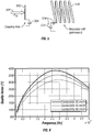
- FIG. 1 shows a plot of power density with the FCC limit curve 100, and the EN curve 102.
- Figure 2 shows a plot of maximum H field, with the FCC curve 200, and the EN curve 202.
- Figures 1 and 2 illustrate how the US limits are more generous at frequencies below 30MHz and could offset the effect of reduced antenna efficiency at low frequency. This study tests a range of frequencies to see which frequencies are the best for wireless power transfer.
- This application also provides an exemplary theoretical analysis of various aspects of wireless energy and power transfer.
- Embodiments disclosed herein describe antenna types.
- a loop antenna is a "magnetic" antenna and may be less sensitive to changes in its surroundings than a dipole, which is an "electric" antenna.
- the loop antenna may have certain advantages when the device is exposed to changes in its surroundings, e.g., when placed on a table, held in the hand, or put in a pocket, based on stray capacitance, or other effects.
- an air loop antenna is used.
- Another embodiment may use a loop antenna with a ferrite core, or others may be used.
- an air loop antenna may be preferred over a loop antenna with a ferrite core.
- the air loop antenna may be more resistant to detuning from permanent magnets or other magnetic influences in its vicinity.
- the air loop antenna will, in general, be more efficient than the ferrite loop antenna, since the ferrite core can cause losses.
- the ferrite antenna is often heavier, and cannot typically have components placed "inside" it. In contrast, other components can be placed inside the loop of an air loop antenna.
- the form-factor of the loop may be modified or otherwise adapted to fit within a form-factor of certain portable devices being charged.
- the same type of antenna may be used for both transmitter and receiver.
- the transmit and receive antennas can be the same or different sizes.
- An embodiment describes a tuning circuit that becomes part of the antenna circuit.
- a typical loop antenna is inherently inductive.
- a capacitive element may be used in the tuning circuit to induce resonance in the antenna. Even though a loop antenna is less sensitive to changes in its surroundings than a dipole antenna, it will still be detuned to some degree by changes in its surroundings. Therefore, it may be desireable in certain embodiments to adaptively tune either the transmitter antenna or the receiver antenna or both, to maintain the quality of the link therebetween.
- Adaptive tuning is achieved in one embodiment by changing the value of a capacitive element used in series with the loop antenna to adjust the resonant frequency of the circuit.
- a goal is to choose tuning components with high quality factors (Q) to ensure that that the Q of the overall receiver circuit is degraded as little as possible.
- Q quality factors
- high Q is used to maximize efficiency, even at the cost of narrow bandwidth.
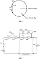
- Figure 3 illustrates an air loop antenna of an embodiment.
- the antenna can, for example, be placed around the perimeter of a mobile device.
- the loop will be assumed circular, but can be of other shapes.
- a capacitor 302 is used with the loop inductive resonator to bring the loop antenna to resonance.
- the required capacitance can be calculated for any of a number of frequencies.
- the capacitor 302 can be a high Q fixed chip capacitor in parallel with a high Q varactor diode operating as a voltage-tunable capacitor to bring the receiver air loop to resonance and to maintain tuning.
- Figure 4 shows a schematic of the series-resonant circuit formed with tuning circuit 400, that itself is formed of variable capacitance 402, in series with its equivalent series resistance 404.
- a fixed capacitor is shows as 406 in series with its ESR 408.
- the antenna overall ohmic resistance 410 is shown separated as radiation resistance 410 in series with overall antenna resistance 412. Load resistance 414 and inductance 416 are also shown.
- One embodiment selects a tuning range of roughly +/-5 percent of the chosen operating frequency, so as to cover variations in the capacitance and detuning from external factors.
- the varactor's tuning range could be approximately +/-10 percent the fixed capacitance value.
- Components used preferably have a high Q, so that they degrade the overall Q of the circuit as little as possible.
- tuning is carried out solely at the transmitter.
- no varactor diode need be located at the receiver and the transmitter tracks the receiver resonant frequency. This is dependent on how much resonant frequency of the receiver loop is affected by changes in the environment near the loop.
- the opposite configuration can also be used.
- a very small capacitance may be required to bring the loop to resonance.
- only a varactor diode or only a fixed capacitor would be used without the other.
- Another effect to be considered is the self-resonance of the loop, especially at higher frequencies. This effect will occur as inter-winding capacitance and stray capacitances on the loop antenna come into resonance with the inductance of the winding itself. This decreases as frequency increases.
- Exemplary high Q/low ESR capacitors with capacitances from the low picofarad to the low nanofarad range can be obtained commercially, e..g, from AVX Corp. Details of some potentially suitable AVX capacitors are tabulated in Table 3, although any number of other devices may be used.
- Another embodiment uses MEMS (Microelectromechanical Systems) varactors. This may lower the power consumption.
- the circuit of Figure 4 at resonance is analyzed to evaluate performance.
- the varactor will be replaced by a fixed value capacitor one-tenth the size of the main fixed capacitor.
- the AVX data will be used for both capacitors.
- the tuning circuit 100 in Figure 4 is modeled as a single R/C impedance. Values used are:
- the inventors found that when the resistances of the tuned antenna are matched to the load resistance, the maximum amount of power P rx is available at the load. In other words, the optimum condition is when
- the transmitter circuit is modeled as a resonant loop where the loop is power-matched to the source.
- the transmitter antenna could, for example, sit vertically on a bench or a table inside a home, within a wall, around a wall power outlet, on or within a garage floor, behind a refrigerator, etc.
- the loop will be assumed circular, as Figure 3 .
- a single wire loop transmitting antenna of Figure 3 having a wire diameter of 10 cm radius, wire radius of 1mm, has an inductance of approximately 840 nH. Different frequencies will require different capacitance values for resonance with this antenna.
- 1.3 Mhz will require a capacitor of 17.85 nF; 13.56 Mhz will require 164.1 pF; 64 Mhz will require 7.365 pF; 250 Mhz will require .483 pF and 500 Mhz will require 0.121 pF.
- antennas A number of different antennas are described as embodiments herein.
- the antennas were built of 1.5 mm 2 copper wire and fixed onto a wooden frame.
- the transmit antenna has a radius of 0.2 m, 6 turns, and 3Mhz operating frequency.
- the matching is realized with two tunable capacitors.
- the receiving antenna has a radius of 0.1 m. Before considering power transfer/pathgain, the antennas were tuned and measured independently. The resulting characteristics are summarized in Table 6.
- a quality factor increase may further increase power transfer.
- the quality factor for example, can be increased using a Matlab simulation.
- Equation above shows that for a practical antenna, the loop radius has a high impact on the path gain.
- Figure 5 illustrates a second embodiment of the antennas.
- This embodiment obtains a maximized power transfer between a coupling loop 500 to which the transmitted power 502 is delivered.
- the coupling loop radiates to a resonator 510 with optimized Q.
- This embodiment uses a coupling loop which acts as a resonator instead of a coupling network made of two capacitors. This reduces losses by omitting a matching network.
- the coupling between the coupling loop and the antenna can be conceptualized as an ideal transformer.
- the antenna may be made out of e.g., copper tube or the like in order to decrease the loss resistance by increasing the wire surface.
- the surface may be plated with silver (Ag) or another such high conductance material well known in the art. With this type of construction, a quality factor in the order of 10 3 is achieved, as described in greater detail below.
- the resonator part of the antenna may also be optimized for a high quality factor (Q). This is done by increasing the number of turns, increasing the surface of the wire and reducing dielectric losses due to isolation or the mounting of the antenna.
- tunable capacitors 504, 512 may be integrated at the bottom of both antennas.
- the capacitors may be metal plates that are tunable by using three screws 514 to change the distance between the two plates of the capacitor.
- the capacitors dominate the self-capacitance (CS) of the antennas.
- Table 6A illustrates the characteristics of these antennas.
- Table 6A Transmitting antenna (TX) Receiving antenna (RX) Radiums [m] 0.085 0.085 Length [m] 0.078 0.078 Number of turns 7 7 Operating frequency [MHz] Resonance Resonance
- the exemplary embodiments of the antennas are built of copper tube with an outer diameter of 6.0 mm.
- the surface is silver-plated. This protects the copper from corrosion and slightly increases the conductivity of the surface.
- the resulting calculated resonance frequency is 14.4 MHz.
- pathgain is approx. -10 dB, at 1 m, which corresponds to a factor of 0.1. In other words, a transmitting power of 10 watts must be used to receive 1 W at the receiver.
- the system should be defined around the unloaded Q (Q ul ) of the antennas. starting with:
- the total loss resistance of either the Tx or Rx antenna can be defined by: At resonance, it can be written as The resulting current in the TX-antenna can now be specified by Using Equation 1-2, the current can be rewritten as The magnitude of the H-field generated by the current in the TX-antenna in a distance x is and induces a voltage in the RX-antenna.
- the parameter r A is the radius. N the number of turns of the loop-antenna.
- Equation 1-10 The available output power P out can now be calculated with Finally, pathgain is defined as To further simplify and understand the behaviour of Equation 1-10 and Equation 1-9, models for L and C are needed.
- the capacitance can simply be defined over the resonance frequency
- an empiric formula was found to be the most accurate for the type of antenna used in this system.
- the parameter l A is the width of the antenna.
- Equation 1-10 Under the assumption that the separation x between the antennas is large compared to the radius of the antennas rA (x > rA), and with Equation 1-11 and Equation 1-12, Equation 1-10 can be written as:
- the term in brackets in 1-13 is the linear pathgain. Note that this linear pathgain is not a direct function of the frequency or the number of turns, although these parameters are implicitly contained in the quality factor.
- the pathgain is approximately proportional to loop radius rA 6 , if the loop radius is much larger than the loop length l A . It is inversely proportional to the separation x 6 between the antennas. It is also proportional to the quality factor Q ul 2 .
- the resulting simulation showed a pathgain variation of -60 dB per decade which is caused by the term x 6 in Equation 1-13. If Q is doubled, for example from 1000 to 2000, pathgain increases by 6 dB. If the distance is doubled, pathgain decreases by 18 dB.
- the exemplary defined parameters are valid for both TX-and RX-antennas, and hence can assist with forming an optimal antenna for the parameters.
- the simulation also calculates the reactive voltages.
- the reactive voltages occurring at the inductance and the capacitance are directly proportional to the quality factor and proportional to the square root of the transmitting power as set forth in Equation 1-14.
- Both reactive voltages will be very high in a practical implementation, thus planning for those voltages becomes more critical.
- the voltages may be 2.7 kV. If a plate capacitor is used with a plate distance of 0.01 m, the resulting field strength is 270 kV/m.
- Capacitors that can withstand these high voltages become critical. For example, it may be necessary to use 2000 v or 3000 V or higher voltage withstanding capacitors. It is believed that at least one reason why systems of this type did not operate properly in the past is that they were not properly sized for the amount of reactive voltage at was actually present. In fact, the unexpectedly high voltage above 2KV is found as part of these reactive voltages even when much smaller voltages are being transmitted. This unexpectedly high voltage needs to be handled by the circuit components.
- Equation 1-1 The fundamental equation about the quality factor is given by Equation 1-1 above.
- Figure 6 illustrates a plot of Q vs frequency for a number of different frequencies.
- the quality factor is also inversely proportional to the resistance R.
- This resistance consists of a loss resistance (R l ) and a radiation resistance (R r ). Both should be minimized in order to increase the quality factor.
- the loss resistance is dependent of the material used to build the antenna, and due to the skin effect of frequency used for the system.
- a highly conductive material with good skin effect is preferable.
- the resonance frequency of 13 MHz used during testing described herein is below this ideal frequency. This is because self resonance, which is the resonance frequency without the tunable capacitor , below the resonator of the antennas is around 35 MHz. If the resonator is used at this frequency without the tunable capacitor, the sensitivity of the antenna against close-by objects may become significant.
- An embodiment minimizes this effect and at the same time makes it possible to change the resonance frequency.
- a tunable capacitor of a value which dominates the self-capacitance of the resonator is used for this purpose.
- the added capacitance lowers the resonance frequency of the antenna.
- Q ⁇ 0 ⁇ ⁇ may be used as a starting point, where ⁇ 0 is the center or resonance frequency and ⁇ corresponds to the 3 dB-bandwidth. Q can therefore be found by measuring the two parameters ⁇ 0 and ⁇ .
- the 3 dB-bandwidth can be found as follows.
- the impedance Z of a first order series RLC-circuit is given by With the help of and the inductance L and capacitance C can be written in terms of Q and ⁇ 0 . If Equation 2-5 and Equation 2-6 is used in Equation 2-2, impedance can be expressed with The duality factor Q can also be used to define the bandwidth (like in Equation 2-1)
- the impedance phase is given by the inverse tangent of the imaginary part of Z , divided by the real part of Z. In this division, R cancels out. If in addition Equation 2-8 is used and the function is evaluated at the upper cut-off frequency, then the phase is given by
- Equation 2-11 corresponds to an angle of 90 degrees which implies that the imaginary part of Z is equal to the real part of Z.
- Equation 2-1 can be used to calculate Q.
- the Q value of such an antenna can be actually determined.
- a second embodiment of the antenna is shown in Figure 7 .
- a coupling loop 700 is placed approximately 0.1 m away from the main part of the antenna 710.
- a plate capacitor is formed between two copper plates 721, 722.
- Screws 723, 724, 725 are formed of a capacitively-inert material such as polyimide. These screws are used to adjust the capacitance provided by the tuneable capacitor 720 and in turn adjust the resonance frequency of the antenna.
- a glass body 730 or other dielectric may be below the antenna to minimize losses due to obstacles below the antenna.
- surface conduction is important to maximize Q.
- a silver plating or other noncorrosive material may be applied to protect the copper from corrosion.
- the coupling loop 700 may be formed of the same copper tube material, but has only one turn and about half the diameter of the antenna.
- the coupling loop is placed around 0.1 m away from the antenna to get a 50 W matching.
- L is the inductance of the resonator itself
- Cs is the self-capacitance of the resonator
- CT is the tuneable capacitor associated with the resonator
- Rr is the radiation resistance
- Rl the loss resistance of the resonator
- Table 8 shows the values obtained for the current values of antenna parameters.
- An exemplary test arrangement for the pathgain-measurement may be carried out to obtain the actual values. This measurement may completely decouple the transmitter from the receiver, to avoid power transfer on the surface of the coaxial shields and on the power lines.
- a signal generator and a battery powered spectrum analyzer may be used on the transmitter and the receiver side respectively.
- the energy returning from the transmitting antenna is measured with a power meter which was connected through a directional coupler.
- the forward coupling port of the directional coupler was terminated with a 50 W load.
- the matching was at least 20 dB. Matching can be varied by adjusting the distance between the antenna and the coupling loop.
- the spectrum analyzer iss directly connected to the receiving antenna.
- the same resonance frequencies are used for both antennas. Detuning results in a dramatically reduced power transfer.
- the receiving antenna may use a tuning aid, e.g., a Teflon bar that is selectively insertable into the tunable capacitor of the antenna, resulting in a resonance-shift of approximately 40 kHz, or may use an adjustable capacitor as previously described. For each distance measured, the receiving antenna is tuned to receive the maximum power available. The transmitting antenna is tuned by slightly adjusting the signal generator's frequency.
- Table 9 shows the resulting measured pathgains. Table 9 Distance [m] Level at receiver [dBm] Level at transmitter [dBm] Pathgain [dB] 1.1 3.3 12.5 -9.2 1.5 -3.7 12.5 -16.2 2.0 -10.5 12.5 -23.0 2.5 -18.5 12.5 -31,0 3.0 -25.3 12.5 -37.8
- the reactive voltage can easily exceed several kV, it may be useful to test the antenna prototypes to determine that reactive voltage, in order to allow determination of proper sizing for the capacitors.
- An electrically decoupled system may be used.
- a source signal from the signal generator is amplified by a 50 dB RF amplifier.
- the 20 dB attenuator in-between is used to limit the available power on the TX antenna.
- the 3 dB attenuator after the amplifier is used to protect the amplifier in case of a mismatched antenna.
- a power meter is used to show the energy returning from the antenna.
- a small light bulb 50 W / 3 W may be used to indicate the received power. Tuning and matching was realized by using the tuning aid, by varying the frequency of the signal generator and by varying the distance between the antennas and the coupling loop.
- sensitivity to close-by objects or humans may cause a shift of the resonance frequency due to e.g., stray capacitance. This may be mitigated by a shield, e.g., a slotted or other shield, disposed around the antenna.
- a shield e.g., a slotted or other shield
- a piece of mica which has a high dielectric strength and very good isolating capabilities is used in place of the polyimide screws noted above. This also raises the quality factor. It is postulated suggesting that less energy is absorbed by the mica compared to the polymer.
- the bandwidth of the exemplary second antennas is somewhat narrow, e.g., around 9 kHz at a resonance frequency of 13 MHz. This results in certain tuning requirements, because both antennas have to work on almost exactly the same resonance frequency.
- An electronic tuning circuit may be used to automatically tune the antenna circuit(s) to maintain coherence. The detuning issue becomes especially important in a system like this where the Q is very narrow. This narrow Q implies narrow bandwidth, which requires that the tuning be closer.
- the exemplary antenna was suspended with two thin nylon strings. Two coupling loops are used to measure transmission (S 12 / S21) instead of reflection (S 11). The coupling loops were placed on both sides of the antenna, about 0.6 m away from the antenna, to achieve an undercritical coupling. That is, when an equal amount of power is dissipated in the external circuit as in the resonator itself, the coupling is said to be critical (and the antenna is matched).
- An undercritical coupling means that more power is dissipated in the resonator than in the external circuit, while an overcritical coupling means that more power is lost in the external circuit than in the resonator.
- the theoretically expected Q for this embodiment is 2877.
- the realized Q of 2263 is 78.6% of the theoretical value.
- the theoretical value was almost reached in this test. It was also noted that higher Q, however, may make the antenna more susceptible to influence by its environment. Thus, in practice, the Q will likely always be lower than the theoretical value.
- the loaded quality factor QL should be half of the unloaded quality factor (Qul) under the condition when the resonator is critically coupled.
- the foregoing transmitter and receiver apparatus may also be combined in another embodiment as a transceiver: i.e. a device adapted to both transmit and receive power.
- a transceiver i.e. a device adapted to both transmit and receive power.
- This may comprise for example a common form factor (e.g., a single unit or "box" having both transmit and receive antennas and circuitry disposed therein).
- the device may be used as a repeater to receive energy from one source via the receive antenna, and then transmit the received power to another source (or back to the same on) using the transmit antenna. These events (transmission and reception) may occur at the same time or with one delayed relative to each other.
- Values can be modified depending on the polarization, strength, geometry, relative spacing and placement, and other factors associated with the transmit and receive antennas, or may also be conducted according to any number of well known multiple access schemes such as e.g., frequency division or FDMA (e.g.. wherein the resonant frequency of the first antenna (receiver or transmitter) is different or separated from that of the second antenna (transmitter or receiver).
- FDMA frequency division
- the two antennas may use the same or different frequency, and be time-divided or slotted as to their operation (e.g., TDMA).
- CSMA collision detection
- the transmitter before transmitting, detects the state of the receiver (e.g., whether in resonance, generating current, etc.) and uses this as a gating criterion for transmission).
- Another embodiment uses a "resonant frequency hopping" approach, wherein multiple access or other aims, such as defeating or mitigating Rayleigh or antenna diversity fading or other such issues, is accomplished by way of periodically or deterministically or psuedorandomly hopping the resonant frequency as a function of time.
- the transmitter and receiver may "seed" corresponding deterministic algorithms so as to mutually generate a common hop sequence that allows them to maintain synchronized.
- "in-band” (e.g., modulated power signal) signaling may be used to transmit the hop sequence in advance (or as it proceeds) to the receiver from the transmitter; e.g ..
- a separate low power transmitter e.g., RF or Bluetooth, can be used to synchronize the specific information. Clocking information may also be sent in an analogous way.
- a passive "collision detection" or CD approach is used, such as where the transmitter attempts to transmit, and determines whether an interfering operation is occurring at the same time. For example, the determination may be by detecting a resonant frequency, a transmission efficiency, a feedback from a receiver, or some other detection. This interfering operation may be caused by the operation of the receiver, a parasitic or stray capacitance effect, a loss of tuning, or other similar effect.
- the transmitter may take an action at that point to avoid the issue.
- the transmitter can terminate the ongoing transmission and retry a later time.
- One example of this is via a random backoff via an anti-collision algorithm.
- One embodiment allows the power has transmitted to be stored in a storage part such as a battery. Because of this, the device can the power transmission can be stopped temporarily; while still allowing the powered device to operate.
- the transmitter can attempt to tune itself to a different resonant frequency so as to mitigate the interference and/or attempt to tune or otherwise vary the operation of the receiver.
- Another option is to increase the gain so as to increase an energy transfer rate. This may operate to "blast through” the interference as it were).
- a system of adjusting polarization or orientation of transmitter and/or receiver can be used, such as via a motor drive or similar mechanism that physically alters the position of the antenna(s).
- Another embodiment uses signaling information between the devices that relates to the level or rate of power transfer as determined by the receiver (e.g., "here's what I'm actually receiving, so you can compare this to what you are actually sending to tune yourself, transmitter").
- the aforementioned multiple access schemes can be implemented in this fashion; e.g., backoff or CD based on a drop in receiver received power as communicated back to the transmitter via a communication channel.
- multiple transmitters and/or receivers may be used, and the aforementioned features implemented as between the multiple transmitters (and/or receivers).
- the FDMA, TDMA, CSMA or CD techniques may be applied as between two potentially conflicting transmitters.
- the foregoing functions may be implemented at an electrical or electronic component level; e.g., via simple gate logic or the like implemented as anything from discrete components through highly integrated circuits, as computer programs or applications running on e.g., a micro-controller or digital processor, via firmware disposed on a IC, manually, or in hardware to the degree applicable (e.g .. electromechanical tuners, motors, etc.).
- the present application contemplates the dynamic alteration or variation of one or more antenna or circuit parameters by environmental characteristics.
- this can change antenna characteristics.
- the characteristics that can be changed can include tuning capacitance, resistance value, radius of the loop or coil, e.g. via a thermal effect that causes elongation or contraction of the material used to form the antenna loop(s), thereby changing its effective radius, the properties of the antenna or components in proximity thereto (e.g .. by selectively applying a particular electric field or magnetic field, alignment of dipoles within the material or components might be selectively altered, thereby affecting the properties of the antenna), as well as electrical or electronic processing such as power signal processing, filtration, modulation, and others.
- the (predominantly) magnetic field of the transmitter is modulated or impressed with information so as to transfer information, along with power.
- this information comprises control signaling between the receiver and transmitter, thereby obviating any separate data or communications link (and hence simplifying the system and making it more robust).
- the transmitter may modulate the transmitted narrowband signal as a function of time, e.g., via an amplitude modulation, phase modulation. sideband or frequency modulation; e.g., GMSK or sideband shift up or down to encode a data "0" or "1", pseudo-noise modulation. or other technique.
- This allows transfer of information relating to inter alia transmitter parameters (such as resonant frequency. polarization, etc. that might otherwise allow the receiver to better "lock on” to the transmitter to optimize power transfer.
- Duty cycle, clock, or timing information might also be encoded: e.g., windows during which the transmitter will be operational, to synchronize time frames of reference etc.
- antennas are not typically self-resonant.
- the antennas are either capacitive (dipole antenna) or inductive (loop antenna). They can be approximated for example by a first-order series RC or parallel RL circuit. They are brought to resonance by tuning with a reactor of an opposite kind.
- the equivalent circuit of such an antenna is shown in Figure 8 for the capacitive case.
- One main element of the antenna is the radiation resistance Rr.
- this resistor models the radiated power.
- the loss resistor RL accounts for the conduction and dielectric losses of the antenna.
- the capacitor C represents the reactive component of the antenna.
- This, together with the external matching inductor L forms a resonant circuit, which is tuned to the operating frequency.
- This circuit can also be modeled as an equivalent representation as a parallel resonant circuit.
- the antenna and matching network impedance is complex conjugate matched at resonance to the antenna impedance.
- a similar circuit can be derived for the case of an inductive antenna.
- Equation A3 Three important relations can be derived from Equation A3 and Equation A4:
- Equation 5 illustrates that the antenna efficiency is proportional to the cube of the relative antenna size and therefore also proportional to the cube of the absolute antenna size. Increasing the size by a factor of 10 results in an improvement of antenna efficiency of 30dB (factor 1000), assuming that the antenna quality factor is kept constant.
- Equation 7 shows that the antenna quality factor is proportional to the antenna efficiency. Increasing by 10 times the antenna quality factor yields an increase of the antenna efficiency of 10dB (factor 10), assuming a constant relative antenna size. Antenna efficiency is proportional to the cube of the frequency. An increase by a factor of 10 in the frequency leads to an improvement of the antenna efficiency by 30dB (factor 1000), assuming that the antenna size and the antenna quality factor are kept constant.
- the gain does not present a physical limit.
- the characteristics of an antenna show a strong dependence on the point (in terms of distance) where their fields are observed. A distinction between near field and far field is often made.
- the electromagnetic energy is mainly stored and not radiated (stationary wave).
- the boundary for this region is usually defined as:
- transition region Between the near-field and the far-field a transition from a stationary into a propagating wave occurs. This is the so-called transition region.
- the boundary between the near-field and the far-field is in the frequency range of 10 to 100MHz.
- Friis transmission equation describes the ratio of received power to power of a transmit antenna. assuming a certain receive and transmit antenna gain, as well as a certain separation between these antennas:
- the radiated fields of an electrically small dipole will be considered As a basis for this general radio wave propagation model.
- the dipole can also be used to model a loop antenna because of the principle of duality of the electric and magnetic field. Because of this, the electric field component of a dipole corresponds to the magnetic field component of the loop and vice versa.
- Equation 13 and Equation 14 show the components of the electric and the magnetic field of a small dipole.
- the radial component of the electric field has been omitted, as it accounts only for the reactive energy that is stored in the near-field.
- r is the distance to the antenna and not the antenna radius.
- Equation 17 is the propagation law for like antennas (propagation from a dipole to another co-polarized dipole or propagation from a loop to another co-polarized loop).
- Equation 18 is the propagation law for unlike antennas (propagation from a dipole to a co-polarized loop or propagation from a loop to a co-polarized dipole).
- the path gain in the near-field is much higher than what would be expected by applying the far-field theory (Friis equation).
- the term "power” as used herein can refer to any kind of energy, power or force transfer of any type.
- the receiving source can be any device that operates from stored energy, including a computer or peripheral, communicator, automobile, or any other device.
- Myriad applications of the foregoing transmitter, receiver and transceiver apparatus of the invention are recognized. By way of example and without limitation, such applications include: (i) powering or charging portable computers. PMDs. client devices. cellular phones. etc.; (ii) powering or charging flat screen or wall-mounted televisions or displays; (iii) powering or charging refrigerators (e.g., by placing a transmitter on the wall behind the refrigerator.
- incandescent, fluorescent or LED ⁇ based lamps with no cords (vi) powering or charging home or office appliances such as toasters, blenders, clocks, televisions, microwave ovens, printers, computers, etc.: (vii) powering or charging multiple devices simultaneously (e.g., through the use of a substantially omni-directional transmitter arrangement); and (viii) powering or charging devices where the presence of electrical conductors with voltage would represent a hazard; e.g., near water, near children, etc.
- the terms “electrical component” and “electronic component” are used interchangeably and refer to, without limitation, components adapted to provide some electrical or electronic function, including without limitation inductive reactors (“choke coils”), transformers, filters, gapped core toroids, inductors, capacitors, resistors, operational amplifiers, varactors, MEMS devices, FETs and other transistors and diodes, whether discrete components or integrated circuits, whether alone or in combination.
- inductive reactors (“choke coils”), transformers, filters, gapped core toroids, inductors, capacitors, resistors, operational amplifiers, varactors, MEMS devices, FETs and other transistors and diodes, whether discrete components or integrated circuits, whether alone or in combination.
- integrated circuit refers to any type of device having any level of integration (including without limitation ULSI, VLSI, and LSI) and irrespective of process or base materials (including, without limitation Si, SiGe, CMOS and GAs).
- ICs may include, for example, memory devices (e.g., DRAM, SRAM, DDRAM, EEPROM/Flash, ROM), digital processors, SoC devices, FPGAs, ASICs, ADCs, DACs and other devices, as well as any combinations thereof.
- digital processor is meant generally to include all types of digital processing devices including, without limitation, digital signal processors (DSPs), reduced instruction set computers (RISC), general-purpose (CISC) processors, microprocessors, gate arrays (e.g., FPGAs), Reconfigurable Compute Fabrics (RCFs), and application-specific integrated circuits (ASICs).
- DSPs digital signal processors
- RISC reduced instruction set computers
- CISC general-purpose
- microprocessors e.g., FPGAs
- RCFs Reconfigurable Compute Fabrics
- ASICs application-specific integrated circuits
- the terms “computing device”, “client device”, and “end user device” include, but are not limited to, personal computers (PCs) and minicomputers, whether desktop, laptop, or otherwise, set-top boxes such as the Motorola DCT2XXX15XXX and Scientific Atlanta Explorer 2XXXl 3XXX/ 4XXXl 8XXX series digital devices, personal digital assistants (PDAs) such as the Blackberry® or "Palm®” family of devices, handheld computers, personal communicators, J2ME equipped devices, cellular telephones, or literally any other device capable of using power, or interchanging data with a network.
- PCs personal computers
- minicomputers whether desktop, laptop, or otherwise, set-top boxes such as the Motorola DCT2XXX15XXX and Scientific Atlanta Explorer 2XXXl 3XXX/ 4XXXl 8XXX series digital devices
- PDAs personal digital assistants
- Blackberry® or "Palm®” family of devices handheld computers
- personal communicators J2ME equipped devices
- memory includes any type of integrated circuit or other storage device adapted for storing digital data including, without limitation, ROM, PROM, EEPROM, DRAM, SDRAM, DDR/2 SDRAM, EDOIFPMS, RLDRAM, SRAM, “flash” memory (e.g., NANDINOR), and PSRAM.
- the operations and/or flowcharts described herein may be carried out on a computer, or manually. If carried out on a computer, the computer may be any kind of computer, either general purpose, or some specific purpose computer such as a workstation.
- the computer may be an Intel (e.g., Pentium or Core 2 duo) or AMD based computer, running Windows XP or Linux, or may be a Macintosh computer.
- the computer may also be a handheld computer, such as a PDA, cellphone, or laptop.
- the method steps and operations described herein can be carried out on a dedicated machine that does these functions.
- the programs may be written in C or Python, or Java, Brew or any other programming language.
- the programs may be resident on a storage medium, e.g., magnetic or optical, e.g. the computer hard drive, a removable disk or media such as a memory stick or SD media, wired or wireless network based or Bluetooth based Network Attached Storage (NAS), or other removable medium or other removable medium.
- the programs may also be run over a network, for example, with a server or other machine sending signals to the local machine, which allows the local machine to carry out the operations described herein.
Landscapes
- Engineering & Computer Science (AREA)
- Computer Networks & Wireless Communication (AREA)
- Power Engineering (AREA)
- Physics & Mathematics (AREA)
- Electromagnetism (AREA)
- Near-Field Transmission Systems (AREA)
- Details Of Aerials (AREA)
- Charge And Discharge Circuits For Batteries Or The Like (AREA)
- Magnetic Resonance Imaging Apparatus (AREA)
- Aerials With Secondary Devices (AREA)
Abstract
Antennas are maintained at resonance with high Q. Techniques of maintaining the high-Q resonance matching are disclosed.
Description
- This application is related to co-owned and co-pending
U.S. patent application Serial No. 11/408,793 Filed April 21, 2006 U.S. patent application Serial No. 111654,883 filed January 17, 2007 entitled "Method and Apparatus for Delivering Energy to an Electrical or Electronic Device Via a Wireless Link", each of the foregoing incorporated herein by reference in its entirety. - This application claims priority from provisional application number
60/904,628, filed March 2, 2007 - A portion of the disclosure of this patent document contains material that is subject to copyright protection. The copyright owner has no objection to the facsimile reproduction by anyone of the patent document or the patent disclosure, as it appears in the Patent and Trademark Office patent files or records, but otherwise reserves all copyright rights whatsoever.
- All figures, tables, and Exhibits are Copyright © 2006, 2007 Third Option, LLC. All rights reserved.
- Delivery of power to portable devices often uses wires of various types to carry out the power delivery. Devices such as cell phones, portable computers, or any other device that can operate from stored power such as a battery, all require and use such a source of power to operate the device and/or charge the battery.
- Techniques of wireless power transfer are disclosed herein.
- Embodiments describe the use of wireless power transfer to a receiving source.
- As used herein, the terms "wireless power" and "wireless energy" include without limitation any form of power or energy, including that associated with electric fields, magnetic fields, electromagnetic energy, or otherwise, that is transmitted between one point, area, location or device and another without having to use a wire line connection.
- An embodiment discloses a wireless powering and charging system. An embodiment describes using a transmitter of a size allowing it to be embedded into another item, e.g., a desk or a shelf, or plugged into a wall, or embedded into another structure or surface such as a wall, floor, door, etc. A receiver is associated with a small mobile unit or client device carried by the user, or mounted on a portable device, vehicle, or with a stationary device such as a lamp, toaster, flat-screen TV on a wall, computer or computerized device, PDA, personal media device, etc. When the receiver is in range of the transmitter, power is delivered to the mobile unit.
- In one embodiment, a wireless powering-charging system is disclosed, based on a transmitter that sends a substantially unmodulated signal or beacon (e.g., the carrier only). A receiver may be tuned to extract energy from the radiated field of the transmitter. The receiver powers an electronic device or charges a battery.
- Other embodiments may use beacons that are slightly modulated.
- Multiple receivers may be used. Multiple transmitters may be used to transmit to one or multiple receivers.
- The antenna used by this system allows an efficient means of energy transmission and reception. The antenna is preferably of a small size to allow it to fit into a mobile, handheld device where the available space for the antenna may be limited. An embodiment describes a high efficiency antenna for the specific characteristics and environment for the power being transmitted and received.
- Antenna theory suggests that a highly efficient but small antenna will typically have a narrow band of frequencies over which it will be efficient. Many of skill in the art have, therefore, avoided the use of these antennas, to enable more flexible transmit and/or receive characteristics. In an embodiment, an adaptive tuning circuit is used in certain configurations to allow tuning of an efficient yet narrowband antenna.
- One embodiment describes an efficient power transfer between two antennas by storing energy in the near field of the transmitting antenna, rather than sending the energy into free space in the form of a travelling electromagnetic wave. This embodiment increases the quality factor (Q) of the antennas. This can reduce radiation resistance (Rr) and loss resistance (Rℓ).
- In one embodiment, two high-Q antennas are placed such that they react similarly to a loosely coupled transformer, with one antenna inducing power into the other. The antennas preferably have Qs that are greater than 1000.
- Another embodiment describes maximum Permissible Exposure (MPE) where the maximum exposure limits are defined by European and US standards (as well as others). They are defined in terms of power density limits (W/m2), magnetic field limits (A/m) and electric field limits (V/m). The limits are related through the impedance of free space, 377 W.
- In the US, the applicable standard is FCC CFR Title 47: §2.1091 Radiofrequency radiation exposure evaluation: mobile devices. A mobile device is a transmitting device designed to be used in such a way that the separation distance of at least 20cm is normally maintained between the transmitter's radiating structure(s) and the body of the user or nearby persons. The limits to be used for evaluation are specified in §1.310 of Title 47. - §1.1310 Radiofrequency radiation exposure limits (see Table 1).
-

- In Europe, the applicable standard is EN60215. This has been derived from the ICNIRP (International Commission on Non-Ionizing Radiation Protection) guidelines [ICN], The limits are given in Table 2.
-

- The power density limits and magnetic field limits are of particular interest in one embodiment. Using the data from Table 1 and Table 2, limit curves can be determined.
Figure 1 shows a plot of power density with the FCClimit curve 100, and theEN curve 102.Figure 2 shows a plot of maximum H field, with the FCCcurve 200, and theEN curve 202. -
Figures 1 and 2 illustrate how the US limits are more generous at frequencies below 30MHz and could offset the effect of reduced antenna efficiency at low frequency. This study tests a range of frequencies to see which frequencies are the best for wireless power transfer. - This application also provides an exemplary theoretical analysis of various aspects of wireless energy and power transfer.
- Embodiments disclosed herein describe antenna types.
- A loop antenna is a "magnetic" antenna and may be less sensitive to changes in its surroundings than a dipole, which is an "electric" antenna. The loop antenna may have certain advantages when the device is exposed to changes in its surroundings, e.g., when placed on a table, held in the hand, or put in a pocket, based on stray capacitance, or other effects. In an embodiment, an air loop antenna is used. Another embodiment may use a loop antenna with a ferrite core, or others may be used.
- In one embodiment, an air loop antenna may be preferred over a loop antenna with a ferrite core. The air loop antenna may be more resistant to detuning from permanent magnets or other magnetic influences in its vicinity. The air loop antenna will, in general, be more efficient than the ferrite loop antenna, since the ferrite core can cause losses. The ferrite antenna is often heavier, and cannot typically have components placed "inside" it. In contrast, other components can be placed inside the loop of an air loop antenna. The form-factor of the loop may be modified or otherwise adapted to fit within a form-factor of certain portable devices being charged.
- The same type of antenna may be used for both transmitter and receiver. The transmit and receive antennas can be the same or different sizes.
- An embodiment describes a tuning circuit that becomes part of the antenna circuit. A typical loop antenna is inherently inductive. A capacitive element may be used in the tuning circuit to induce resonance in the antenna. Even though a loop antenna is less sensitive to changes in its surroundings than a dipole antenna, it will still be detuned to some degree by changes in its surroundings. Therefore, it may be desireable in certain embodiments to adaptively tune either the transmitter antenna or the receiver antenna or both, to maintain the quality of the link therebetween.
- Adaptive tuning is achieved in one embodiment by changing the value of a capacitive element used in series with the loop antenna to adjust the resonant frequency of the circuit. The adaptive tuning circuit at the transmitter and/or at the receiver. A goal is to choose tuning components with high quality factors (Q) to ensure that that the Q of the overall receiver circuit is degraded as little as possible. In an embodiment, high Q is used to maximize efficiency, even at the cost of narrow bandwidth.
-
Figure 3 illustrates an air loop antenna of an embodiment. The antenna may have maximum dimensions of 5 cm (i.e. a radius r of 2.5cm) and N turns ofwire 300 of diameter 2brx =500 um is used for one embodiment. The antenna can, for example, be placed around the perimeter of a mobile device. The loop will be assumed circular, but can be of other shapes. Acapacitor 302 is used with the loop inductive resonator to bring the loop antenna to resonance. The capacitor value may be defined as:
- By calculating the inductance of the air loop antenna using the Equation and a wire diameter of 500 um, the required capacitance can be calculated for any of a number of frequencies.
- In one embodiment, the
capacitor 302 can be a high Q fixed chip capacitor in parallel with a high Q varactor diode operating as a voltage-tunable capacitor to bring the receiver air loop to resonance and to maintain tuning.Figure 4 shows a schematic of the series-resonant circuit formed withtuning circuit 400, that itself is formed ofvariable capacitance 402, in series with itsequivalent series resistance 404. A fixed capacitor is shows as 406 in series with itsESR 408. The antenna overallohmic resistance 410 is shown separated asradiation resistance 410 in series withoverall antenna resistance 412.Load resistance 414 andinductance 416 are also shown. - In the circuit, the symbols have the following meanings:

- One embodiment selects a tuning range of roughly +/-5 percent of the chosen operating frequency, so as to cover variations in the capacitance and detuning from external factors. The varactor's tuning range could be approximately +/-10 percent the fixed capacitance value. Components used preferably have a high Q, so that they degrade the overall Q of the circuit as little as possible.
- In one embodiment, tuning is carried out solely at the transmitter. In this embodiment, no varactor diode need be located at the receiver and the transmitter tracks the receiver resonant frequency. This is dependent on how much resonant frequency of the receiver loop is affected by changes in the environment near the loop. The opposite configuration can also be used.
- At higher frequencies, or with larger loop dimensions, or with more loop turns, a very small capacitance may be required to bring the loop to resonance. In an embodiment, only a varactor diode or only a fixed capacitor would be used without the other.
- Another effect to be considered is the self-resonance of the loop, especially at higher frequencies. This effect will occur as inter-winding capacitance and stray capacitances on the loop antenna come into resonance with the inductance of the winding itself. This decreases as frequency increases.
- At a lower operating frequency such as 1.3 MHz, a larger fixed capacitor will be required. For example, the loop antenna with the dimensions given in
Figure 3 with 5 turns of loop antenna would require a fixed capacitance of about 3 nF. Capacitance variations of +/-1 percent (30 pF) are typical for these types of capacitors. As will be shown, this exceeds the tuning range of most available tunable capacitors. Therefore, at low frequencies, one embodiment locates the adaptive tuning only in the transmitter. - Increasing the operating frequency or increasing the number of turns allows reducing the size of the fixed capacitance. A larger number of turns may make the packaging more difficult. Therefore, with a large number of turns, practical implementation for certain types of applications could become difficult. A higher frequency therefore might allow certain benefits in applications where this factor might otherwise be limiting.
- However, at frequencies of 250 MHz and above, the size of fixed capacitor required is extremely small - e.g. on the order of 1 pF for N = 1, and even less for more turns. At these frequencies, the fixed capacitor can be eliminated altogether in some cases, and only a very small tuning capacitor used. This physical limit on capacitor size also places a limit on the frequencies that can be used, for given loop dimensions. A smaller receiver loop size would allow a higher frequency or more loops to be used.
- Exemplary high Q/low ESR capacitors with capacitances from the low picofarad to the low nanofarad range can be obtained commercially, e..g, from AVX Corp. Details of some potentially suitable AVX capacitors are tabulated in Table 3, although any number of other devices may be used.
-

- Note that in general, Q ESR and C are related by the following equation:

- Another embodiment uses MEMS (Microelectromechanical Systems) varactors. This may lower the power consumption.
- The circuit of
Figure 4 at resonance is analyzed to evaluate performance. In a first approach, the varactor will be replaced by a fixed value capacitor one-tenth the size of the main fixed capacitor. The AVX data will be used for both capacitors. Thetuning circuit 100 inFigure 4 is modeled as a single R/C impedance. Values used are: - Irx is the current in the receiver loop
- Prx is the power at the load resistor
- Cser is the equivalent series capacitance of the fixed capacitor and varactor, and
- Rser is the equivalent series resistance of the fixed capacitor and varactor.
- At resonance, the reactances can be neglected since XL = -Xc. Only the resistive (real) losses in the circuit are considered.
- The inventors found that when the resistances of the tuned antenna are matched to the load resistance, the maximum amount of power Prx is available at the load. In other words, the optimum condition is when
- RL_rX + Rr_rx + Rser = Rload_rx. The values may vary by 20% while still staying within "optimum" resonance.
- In the embodiment, therefore, the transmitter circuit is modeled as a resonant loop where the loop is power-matched to the source. An exemplary air loop antenna with maximum dimensions of 20cm (i.e. a radius r of 10cm), a wire radius of 1 mm and a single turn (N = 1) is used for an embodiment, although other types, sizes and dimensions of antenna may be used for the transmitter in other embodiments.
- In one embodiment, the transmitter antenna could, for example, sit vertically on a bench or a table inside a home, within a wall, around a wall power outlet, on or within a garage floor, behind a refrigerator, etc. To simplify calculations, the loop will be assumed circular, as
Figure 3 . A single wire loop transmitting antenna ofFigure 3 , having a wire diameter of 10 cm radius, wire radius of 1mm, has an inductance of approximately 840 nH. Different frequencies will require different capacitance values for resonance with this antenna. For example, 1.3 Mhz will require a capacitor of 17.85 nF; 13.56 Mhz will require 164.1 pF; 64 Mhz will require 7.365 pF; 250 Mhz will require .483 pF and 500 Mhz will require 0.121 pF. - A number of different antennas are described as embodiments herein. For testing of the embodiments, the antennas were built of 1.5 mm2 copper wire and fixed onto a wooden frame.
- The transmit antenna has a radius of 0.2 m, 6 turns, and 3Mhz operating frequency. The matching is realized with two tunable capacitors. The receiving antenna has a radius of 0.1 m. Before considering power transfer/pathgain, the antennas were tuned and measured independently. The resulting characteristics are summarized in Table 6.

- A quality factor increase may further increase power transfer. The quality factor, for example, can be increased using a Matlab simulation. The mathematical investigations done for the simulation, leads to the following approximation for the path gain:

- a = loop radius [m]
- b = wire radius [m]
- Qul = unloaded quality factor
- X = distance between transmitter and receiver antenna [m]
- The Equation above shows that for a practical antenna, the loop radius has a high impact on the path gain.
-
Figure 5 illustrates a second embodiment of the antennas. This embodiment obtains a maximized power transfer between acoupling loop 500 to which the transmittedpower 502 is delivered. The coupling loop radiates to aresonator 510 with optimized Q. This embodiment uses a coupling loop which acts as a resonator instead of a coupling network made of two capacitors. This reduces losses by omitting a matching network. The coupling between the coupling loop and the antenna can be conceptualized as an ideal transformer. - The antenna may be made out of e.g., copper tube or the like in order to decrease the loss resistance by increasing the wire surface. In addition, the surface may be plated with silver (Ag) or another such high conductance material well known in the art. With this type of construction, a quality factor in the order of 103 is achieved, as described in greater detail below. The resonator part of the antenna may also be optimized for a high quality factor (Q). This is done by increasing the number of turns, increasing the surface of the wire and reducing dielectric losses due to isolation or the mounting of the antenna.
- To tune the resonance frequency of the antennas,
tunable capacitors screws 514 to change the distance between the two plates of the capacitor. The capacitors dominate the self-capacitance (CS) of the antennas. Table 6A illustrates the characteristics of these antennas.Table 6A Transmitting antenna (TX) Receiving antenna (RX) Radiums [m] 0.085 0.085 Length [m] 0.078 0.078 Number of turns 7 7 Operating frequency [MHz] Resonance Resonance - The exemplary embodiments of the antennas are built of copper tube with an outer diameter of 6.0 mm. The surface is silver-plated. This protects the copper from corrosion and slightly increases the conductivity of the surface.
- With an exemplary plate-distance of the tuneable capacitor of 8 mm, the resulting calculated resonance frequency is 14.4 MHz.
- Using a Q of 1300, pathgain is approx. -10 dB, at 1 m, which corresponds to a factor of 0.1. In other words, a transmitting power of 10 watts must be used to receive 1 W at the receiver.
- The system should be defined around the unloaded Q (Quℓ) of the antennas. starting with:


 voltage





- Under the assumption that the separation x between the antennas is large compared to the radius of the antennas rA (x > rA), and with Equation 1-11 and Equation 1-12, Equation 1-10 can be written as:

- The term in brackets in 1-13 is the linear pathgain. Note that this linear pathgain is not a direct function of the frequency or the number of turns, although these parameters are implicitly contained in the quality factor. The pathgain is approximately proportional to loop radius rA6, if the loop radius is much larger than the loop length ℓA. It is inversely proportional to the separation x6 between the antennas. It is also proportional to the quality factor Quℓ 2.
- For a given antenna dimension, as the quality factor is increased, the pathgain is improved. This is validated in an embodiment via simulation. The above equations were simulated using Matlab® to test antennas with different sizes and quality factors. The following parameter set was defined to run the script:
- % Parameter definitions
- Q = 1000; % target unloaded quality factor [1]
- N = 7;% number of turns [1]
- r_loop = 85e-3; % radius of loop antenna [m]
- r_wire = 3e-3; % radius of wire [m]
- pitch = 12e-3; % distance between two turns (center to center) [m]
- freq = 13.0e6; % system frequency [Hz]
- dist =1: 0.1 : 3; % distance ofantennas [m]
- P_in = 1% input power [W]
- The resulting simulation showed a pathgain variation
of -60 dB per decade which is caused by the term x6 in Equation 1-13. If Q is doubled, for example from 1000 to 2000, pathgain increases by 6 dB. If the distance is doubled, pathgain decreases by 18 dB. The exemplary defined parameters are valid for both TX-and RX-antennas, and hence can assist with forming an optimal antenna for the parameters. - The simulation also calculates the reactive voltages. The reactive voltages occurring at the inductance and the capacitance are directly proportional to the quality factor and proportional to the square root of the transmitting power as set forth in Equation 1-14.

- Both reactive voltages will be very high in a practical implementation, thus planning for those voltages becomes more critical. With a Q of 1000 and a transmitting power of 10 W, the voltages may be 2.7 kV. If a plate capacitor is used with a plate distance of 0.01 m, the resulting field strength is 270 kV/m. Capacitors that can withstand these high voltages become critical. For example, it may be necessary to use 2000 v or 3000 V or higher voltage withstanding capacitors. It is believed that at least one reason why systems of this type did not operate properly in the past is that they were not properly sized for the amount of reactive voltage at was actually present. In fact, the unexpectedly high voltage above 2KV is found as part of these reactive voltages even when much smaller voltages are being transmitted. This unexpectedly high voltage needs to be handled by the circuit components.
- Definition of the Quality Factor also becomes important, because a major focus of the antenna design process is on optimizing the quality factor. Accordingly, the following describes an in-depth analysis of Q.
- The fundamental equation about the quality factor is given by Equation 1-1 above.

-
Figure 6 illustrates a plot of Q vs frequency for a number of different frequencies. - Note that the proportion of L and C is important in this equation. For a given resonance frequency, there are an infinite number of possible L-C combinations. However, higher Q is obtained when the inductance L is as high as possible compared to the capacitance.
- The quality factor is also inversely proportional to the resistance R. This resistance consists of a loss resistance (Rℓ) and a radiation resistance (Rr). Both should be minimized in order to increase the quality factor.
- The loss resistance is dependent of the material used to build the antenna, and due to the skin effect of frequency used for the system. A highly conductive material with good skin effect is preferable.
- A high resonance frequency increases losses and hence decreases the quality factor. This is why the curve of
Figure 6 decreases at the upper end of the frequency-scale. However, a lower resonance frequency is obtained by increasing the capacitance. This decreases the L/C ratio, and since L is independent of the frequency, this lowers Q. Hence, theFigure 6 curve shows how Q decreases at both the upper and lower end of the frequency-scale, making an ideal quality factor around a frequency of 29 MHz for the given antenna dimensions. - This shows an ideal frequency or frequency range for each antenna geometry.
- The resonance frequency of 13 MHz used during testing described herein is below this ideal frequency. This is because self resonance, which is the resonance frequency without the tunable capacitor , below the resonator of the antennas is around 35 MHz. If the resonator is used at this frequency without the tunable capacitor, the sensitivity of the antenna against close-by objects may become significant.
- An embodiment minimizes this effect and at the same time makes it possible to change the resonance frequency. A tunable capacitor of a value which dominates the self-capacitance of the resonator is used for this purpose. The added capacitance lowers the resonance frequency of the antenna.
- Quality factor typically cannot be measured directly. Instead, the definition

may be used as a starting point, where ω0 is the center or resonance frequency and Δω corresponds to the 3 dB-bandwidth. Q can therefore be found by measuring the two parameters ω0 and Δω. - The 3 dB-bandwidth can be found as follows. The impedance Z of a first order series RLC-circuit is given by





- The impedance phase is given by the inverse tangent of the imaginary part of Z, divided by the real part of Z. In this division, R cancels out. If in addition Equation 2-8 is used and the function is evaluated at the upper cut-off frequency, then the phase is given by

- If the expression in the bracket is simplified, the phase gets dependent only from Q.

- If Q increases, the function in the bracket tends to 1.

- The result from Equation 2-11 corresponds to an angle of 90 degrees which implies that the imaginary part of Z is equal to the real part of Z. Those two points can then be found with a network analyzer, and then Equation 2-1 can be used to calculate Q. Hence, using this framework, the Q value of such an antenna can be actually determined.
- A second embodiment of the antenna is shown in
Figure 7 . Acoupling loop 700 is placed approximately 0.1 m away from the main part of theantenna 710. A plate capacitor is formed between twocopper plates Screws tuneable capacitor 720 and in turn adjust the resonance frequency of the antenna. - A
glass body 730 or other dielectric may be below the antenna to minimize losses due to obstacles below the antenna. - Moreover, as described above, surface conduction is important to maximize Q. A silver plating or other noncorrosive material, may be applied to protect the copper from corrosion.
- The
coupling loop 700 may be formed of the same copper tube material, but has only one turn and about half the diameter of the antenna. The coupling loop is placed around 0.1 m away from the antenna to get a 50 W matching. - The following explains how the resonance frequency of the antenna parts can be determined. In the following equations, L is the inductance of the resonator itself, Cs is the self-capacitance of the resonator and CT is the tuneable capacitor associated with the resonator, Rr is the radiation resistance, Rℓ the loss resistance of the resonator.

- rA= loop radius
- N = number of turns
- lA = length of antenna
- µ0 = 1.2566 · 10-6
- p = pitch of the antenna, corresponds to the distance between two turns plus the diameter of a turn
- ε0 = 8.8542 · 10-12
- A = area of the plate capacitor
- d = distance between the plates
- λ = wavelength at the frequency f0

- σ = conductivity of the metal used for the antenna, 45 · 106 S/m used for calculations
- rw = radius of the copper tube
- Table 8 shows the values obtained for the current values of antenna parameters.

- An exemplary test arrangement for the pathgain-measurement may be carried out to obtain the actual values. This measurement may completely decouple the transmitter from the receiver, to avoid power transfer on the surface of the coaxial shields and on the power lines. A signal generator and a battery powered spectrum analyzer may be used on the transmitter and the receiver side respectively.
- To measure the quality of the matching, the energy returning from the transmitting antenna is measured with a power meter which was connected through a directional coupler. The forward coupling port of the directional coupler was terminated with a 50 W load. During the measurements, the matching was at least 20 dB. Matching can be varied by adjusting the distance between the antenna and the coupling loop.
- On the receiver side, the spectrum analyzer iss directly connected to the receiving antenna.
- The same resonance frequencies are used for both antennas. Detuning results in a dramatically reduced power transfer. The receiving antenna may use a tuning aid, e.g., a Teflon bar that is selectively insertable into the tunable capacitor of the antenna, resulting in a resonance-shift of approximately 40 kHz, or may use an adjustable capacitor as previously described. For each distance measured, the receiving antenna is tuned to receive the maximum power available. The transmitting antenna is tuned by slightly adjusting the signal generator's frequency.
- Table 9 shows the resulting measured pathgains.
Table 9 Distance [m] Level at receiver [dBm] Level at transmitter [dBm] Pathgain [dB] 1.1 3.3 12.5 -9.2 1.5 -3.7 12.5 -16.2 2.0 -10.5 12.5 -23.0 2.5 -18.5 12.5 -31,0 3.0 -25.3 12.5 -37.8 - Moreover, since the reactive voltage can easily exceed several kV, it may be useful to test the antenna prototypes to determine that reactive voltage, in order to allow determination of proper sizing for the capacitors. An electrically decoupled system may be used. A source signal from the signal generator is amplified by a 50 dB RF amplifier. The 20 dB attenuator in-between is used to limit the available power on the TX antenna.
- The 3 dB attenuator after the amplifier is used to protect the amplifier in case of a mismatched antenna. To measure the quality of the matching, a power meter is used to show the energy returning from the antenna. On the receiver side, a small light bulb (50 W / 3 W) may be used to indicate the received power. Tuning and matching was realized by using the tuning aid, by varying the frequency of the signal generator and by varying the distance between the antennas and the coupling loop.
- The results are summarized in the Table 10:
Table 10 Distance [m] 1.2 Pathgain in dB 11 Transmitting power [W] 10 Receiving power [W] 0.8 Approximate reactive voltage [ V]
3.1 Approximate field strength in the tuneable capacitor [kV / m] 310 - In one embodiment, sensitivity to close-by objects or humans may cause a shift of the resonance frequency due to e.g., stray capacitance. This may be mitigated by a shield, e.g., a slotted or other shield, disposed around the antenna.
- In another embodiment, a piece of mica which has a high dielectric strength and very good isolating capabilities is used in place of the polyimide screws noted above. This also raises the quality factor. It is postulated suggesting that less energy is absorbed by the mica compared to the polymer.
- In another configuration, very thin pieces of mica or Teflon are used to hold the capacitor and limit transmitting power.
- There is a tradeoff between Q and bandwidth. Due to the high quality factor, the bandwidth of the exemplary second antennas is somewhat narrow, e.g., around 9 kHz at a resonance frequency of 13 MHz. This results in certain tuning requirements, because both antennas have to work on almost exactly the same resonance frequency. Hence, in another embodiment, the antenna sensitivity to approaching objects as described above is reduced using the shield described above. An electronic tuning circuit may be used to automatically tune the antenna circuit(s) to maintain coherence. The detuning issue becomes especially important in a system like this where the Q is very narrow. This narrow Q implies narrow bandwidth, which requires that the tuning be closer.
- To further evaluate the effects of various external or design factors on Q, various aspects of the experimental setup are considered, including e.g. the glass body under the antenna, the piece of mica in the capacitor, the losses of the coupling loop, and the losses of all the objects within the near field of the antenna.
- To evaluate these factors, the environment of the antenna should be as ideal as possible. Therefore, the exemplary antenna was suspended with two thin nylon strings. Two coupling loops are used to measure transmission (S 12 / S21) instead of reflection (S 11). The coupling loops were placed on both sides of the antenna, about 0.6 m away from the antenna, to achieve an undercritical coupling. That is, when an equal amount of power is dissipated in the external circuit as in the resonator itself, the coupling is said to be critical (and the antenna is matched). An undercritical coupling means that more power is dissipated in the resonator than in the external circuit, while an overcritical coupling means that more power is lost in the external circuit than in the resonator.
- The theoretically expected Q for this embodiment is 2877. The realized Q of 2263 is 78.6% of the theoretical value. The theoretical value was almost reached in this test. It was also noted that higher Q, however, may make the antenna more susceptible to influence by its environment. Thus, in practice, the Q will likely always be lower than the theoretical value.
- A second measurement showed another characteristic of the quality factor. The loaded quality factor QL should be half of the unloaded quality factor (Quℓ) under the condition when the resonator is critically coupled.
- The foregoing transmitter and receiver apparatus (e.g., antenna. and any associated electronic or electrical components) may also be combined in another embodiment as a transceiver: i.e. a device adapted to both transmit and receive power. This may comprise for example a common form factor (e.g., a single unit or "box" having both transmit and receive antennas and circuitry disposed therein). Moreover, the device may be used as a repeater to receive energy from one source via the receive antenna, and then transmit the received power to another source (or back to the same on) using the transmit antenna. These events (transmission and reception) may occur at the same time or with one delayed relative to each other. Values can be modified depending on the polarization, strength, geometry, relative spacing and placement, and other factors associated with the transmit and receive antennas, or may also be conducted according to any number of well known multiple access schemes such as e.g., frequency division or FDMA (e.g.. wherein the resonant frequency of the first antenna (receiver or transmitter) is different or separated from that of the second antenna (transmitter or receiver). As yet another option, the two antennas may use the same or different frequency, and be time-divided or slotted as to their operation (e.g., TDMA).
- In another alternative, a "CSMA" like approach may be used (whether with our without "collision detection"), such as where one device actively or passively detects or senses the activity of the other, and adjusts its behavior accordingly. In one such embodiment, the transmitter, before transmitting, detects the state of the receiver (e.g., whether in resonance, generating current, etc.) and uses this as a gating criterion for transmission).
- Another embodiment uses a "resonant frequency hopping" approach, wherein multiple access or other aims, such as defeating or mitigating Rayleigh or antenna diversity fading or other such issues, is accomplished by way of periodically or deterministically or psuedorandomly hopping the resonant frequency as a function of time. For example, the transmitter and receiver may "seed" corresponding deterministic algorithms so as to mutually generate a common hop sequence that allows them to maintain synchronized. Alternatively. "in-band" (e.g., modulated power signal) signaling may be used to transmit the hop sequence in advance (or as it proceeds) to the receiver from the transmitter; e.g .. "I will hop to frequency X at next interval, and frequency X+Y after that....", and so forth. A separate low power transmitter, e.g., RF or Bluetooth, can be used to synchronize the specific information. Clocking information may also be sent in an analogous way.
- In another embodiment, a passive "collision detection" or CD approach is used, such as where the transmitter attempts to transmit, and determines whether an interfering operation is occurring at the same time. For example, the determination may be by detecting a resonant frequency, a transmission efficiency, a feedback from a receiver, or some other detection. This interfering operation may be caused by the operation of the receiver, a parasitic or stray capacitance effect, a loss of tuning, or other similar effect.
- The transmitter may take an action at that point to avoid the issue.
- In an embodiment, since the interference is typically temporary, the transmitter can terminate the ongoing transmission and retry a later time. One example of this is via a random backoff via an anti-collision algorithm. One embodiment allows the power has transmitted to be stored in a storage part such as a battery. Because of this, the device can the power transmission can be stopped temporarily; while still allowing the powered device to operate.
- The transmitter can attempt to tune itself to a different resonant frequency so as to mitigate the interference and/or attempt to tune or otherwise vary the operation of the receiver.
- Another option is to increase the gain so as to increase an energy transfer rate. This may operate to "blast through" the interference as it were).
- A system of adjusting polarization or orientation of transmitter and/or receiver can be used, such as via a motor drive or similar mechanism that physically alters the position of the antenna(s).
- Any combination of the above can alternatively be used. These features can be implemented at the transmitter, and/or at the receiver basis, or in tandem or coordination between the transmitter and receiver.
- Another embodiment uses signaling information between the devices that relates to the level or rate of power transfer as determined by the receiver (e.g., "here's what I'm actually receiving, so you can compare this to what you are actually sending to tune yourself, transmitter"). Moreover, the aforementioned multiple access schemes can be implemented in this fashion; e.g., backoff or CD based on a drop in receiver received power as communicated back to the transmitter via a communication channel.
- As yet another alternative embodiment, multiple transmitters and/or receivers may be used, and the aforementioned features implemented as between the multiple transmitters (and/or receivers). For example, the FDMA, TDMA, CSMA or CD techniques may be applied as between two potentially conflicting transmitters.
- The foregoing functions may be implemented at an electrical or electronic component level; e.g., via simple gate logic or the like implemented as anything from discrete components through highly integrated circuits, as computer programs or applications running on e.g., a micro-controller or digital processor, via firmware disposed on a IC, manually, or in hardware to the degree applicable (e.g .. electromechanical tuners, motors, etc.).
- Moreover, the present application contemplates the dynamic alteration or variation of one or more antenna or circuit parameters by environmental characteristics. For example, this can change antenna characteristics. The characteristics that can be changed can include tuning capacitance, resistance value, radius of the loop or coil, e.g. via a thermal effect that causes elongation or contraction of the material used to form the antenna loop(s), thereby changing its effective radius, the properties of the antenna or components in proximity thereto (e.g .. by selectively applying a particular electric field or magnetic field, alignment of dipoles within the material or components might be selectively altered, thereby affecting the properties of the antenna), as well as electrical or electronic processing such as power signal processing, filtration, modulation, and others.
- For example, in one embodiment, the (predominantly) magnetic field of the transmitter is modulated or impressed with information so as to transfer information, along with power.
- In another embodiment this information comprises control signaling between the receiver and transmitter, thereby obviating any separate data or communications link (and hence simplifying the system and making it more robust). For instance, the transmitter may modulate the transmitted narrowband signal as a function of time, e.g., via an amplitude modulation, phase modulation. sideband or frequency modulation; e.g., GMSK or sideband shift up or down to encode a data "0" or "1", pseudo-noise modulation. or other technique. This allows transfer of information relating to inter alia transmitter parameters (such as resonant frequency. polarization, etc. that might otherwise allow the receiver to better "lock on" to the transmitter to optimize power transfer. Duty cycle, clock, or timing information might also be encoded: e.g., windows during which the transmitter will be operational, to synchronize time frames of reference etc.
- The theoretical limits on antenna performance are explained herein. Aspects such as the antenna efficiency, quality factor (bandwidth) and size are considered. In addition, a model for the radio wave propagation in the near-field and in the far-field is established.
- An electrically small antenna is an antenna that can be fitted into a fraction of a radiansphere, which is a sphere of radius rmax

- where: k is the wavenumber in m-1
- ℓ 1is the wavelength in m
- c is the speed of light 299792458 ms-1
- f is the frequency in Hz, and
- dmax is the diameter of the radiansphere
- The antennas used for this application will be electrically small in almost all cases (i.e. kr < 1), where kr =d/ℓ O.
- Electrically small antennas are not typically self-resonant. For low frequencies, the antennas are either capacitive (dipole antenna) or inductive (loop antenna). They can be approximated for example by a first-order series RC or parallel RL circuit. They are brought to resonance by tuning with a reactor of an opposite kind.
- The equivalent circuit of such an antenna is shown in
Figure 8 for the capacitive case. One main element of the antenna is the radiation resistance Rr. In the equivalent circuit, this resistor models the radiated power. The loss resistor RL accounts for the conduction and dielectric losses of the antenna. The capacitor C represents the reactive component of the antenna. This, together with the external matching inductor L forms a resonant circuit, which is tuned to the operating frequency. This circuit can also be modeled as an equivalent representation as a parallel resonant circuit.
- is the source resistance in Ω

- Ra the antenna resistance in Ω
- RL is the loss resistance, in Ω
- Rr is the radiation resistance in Ω
- is the resonance frequency in rads-1

- L is the matching inductance in H
- C is the antenna capacitance in F
- (eq A-2) For maximum power transfer, the antenna and matching network impedance is complex conjugate matched at resonance to the antenna impedance.
- A similar circuit can be derived for the case of an inductive antenna.
- Applicants believe that there are fundamental limits on the efficiency and quality Factor of such an antenna. If a certain antenna performance is required, the size of an antenna cannot be reduced to an arbitrary value. Like the well-known Shannon limit in communication theory, which relates channel capacity to bandwidth and dynamic range, there is also a fundamental limit in antenna theory that relates minimum antenna size to the radiation quality factor.
- There have been many attempts to calculate the theoretical limits on antenna size. The fundamental work was done by Chu [CHU] and Harrington [HAR]. Their theory states that the antenna is completely enclosed by a sphere of radius r, The field outside the sphere, can be expressed as a sum of weighted spherical waves propagating radially outward. Each wave (mode) exhibits power orthogonality and therefore carries power independently from the others.
- It can be mathematically proven that a particular field outside the sphere can be generated with an infinite number of different source distributions. The field outside the sphere is therefore independent from a particular implementation of the antenna. From Chu's calculation it has been shown that an antenna that excites only one mode (either TE01 or TM01) achieves the lowest possible radiation quality factor of any linearly polarized antenna. Based on the above-described fundamental work. Hansen derived an approximate analytical expression for this quality factor Qr [HAN], which has been cited many times in the literature. Mclean further developed and corrected the work from Hansen [MLE], giving an exact expression for the radiation quality factor Qr of a linear polarized antenna:

- Qr is the radiation quality factor (unitless)
- ω is the radian frequency in rads-1
- Wc is the time-averaged, non-propagating, stored electric energy in J
- Wm is the time-averaged, non-propagating, stored magnetic energy in J
- Pr is the radiated power in W
- This equation shows that the dominant term for electrically small antennas (k; « 1) is the cubic term. However, for large antennas (k; » 1) the radiation quality factor will be governed by the linear term.
- A physical implementation of an antenna exhibits losses, i. e. its radiation efficiency is smaller than unity due to non-ideal conductors and dielectrics. The reduction of the efficiency has an impact on the overall quality factor, called the antenna quality factor. Assuming the antenna is power-matched to the source, the antenna quality factor Qa results in:

where: - Q" is the antenna quality factor (unitless)
- Three important relations can be derived from Equation A3 and Equation A4:
- For small antennas the efficiency is proportional to the cube of the relative antenna size and therefore also proportional to the cube of the antenna size and to the cube of the frequency:

- For large antennas the efficiency is proportional to the relative antenna size and therefore also proportional to the antenna size and the frequency:

- In general the radiation efficiency is proportional to the antenna quality factor:

- For the antenna models in
Figure 4 andFigure 5 the values for radiation equality factor Qr and radiation efficiency ηr are given as:


- ηr is the radiation efficiency (unitless)
- Za is the antenna input impedance in Ω
- Yd is the antenna input admittance in Ω-1
- Pr is the radiated power at resonance in W
- Pm is the power input to the antenna at resonance in W
- This shows that for a given radiation efficiency, reducing antenna size leads to increased antenna quality factor. For a given antenna size, decreasing radiation efficiency results in lower antenna quality factor. Consequently, for a given radiation efficiency, a higher antenna quality factor is the penalty for a small antenna size.
- The antenna quality factor decreases with increasing frequency and increasing antenna size when the radiation for the wireless powering and charging system the antenna efficiency is the most important criterion, as this determines how much power can be transmitted between two antennas.
Equation 5 illustrates that the antenna efficiency is proportional to the cube of the relative antenna size and therefore also proportional to the cube of the absolute antenna size. Increasing the size by a factor of 10 results in an improvement of antenna efficiency of 30dB (factor 1000), assuming that the antenna quality factor is kept constant. - Equation 7 shows that the antenna quality factor is proportional to the antenna efficiency. Increasing by 10 times the antenna quality factor yields an increase of the antenna efficiency of 10dB (factor 10), assuming a constant relative antenna size. Antenna efficiency is proportional to the cube of the frequency. An increase by a factor of 10 in the frequency leads to an improvement of the antenna efficiency by 30dB (factor 1000), assuming that the antenna size and the antenna quality factor are kept constant.
- Unlike the fundamental limits on efficiency and quality factor that have been described above, the gain does not present a physical limit. However, as opposed to the gain, there is a good knowledge of the directivity that can be achieved with certain antenna types. The directivity is linked to the gain as follows:

- According to Balanis [BAL], the directivity of a small dipole is D=1.5. The same directivity applies also to a small loop. This similarity becomes clear when the principle of duality of the electric and magnetic field is applied, as a small loop can be described with the help of a magnetic dipole.
- Higher directivities can be expected from antennas that are not electrically small. This is the case e.g. for the dipole as can be seen from Figure A1. If the maximum antenna dimension is in the order of a wavelength, the directivity is higher than that of the small dipole. However, for the wireless powering and charging system this is only the case for frequencies above 1 GHz.
- The characteristics of an antenna show a strong dependence on the point (in terms of distance) where their fields are observed. A distinction between near field and far field is often made. In the near-field region, the electromagnetic energy is mainly stored and not radiated (stationary wave). The boundary for this region is usually defined as:
- Near-field: In the near-field region the electromagnetic energy is mainly stored and not radiated (stationary wave). The boundary for this region is usually defined as:

- k is the wave number, and
- r the observation distance to the antenna.
- In the far-field region most of the electromagnetic energy is radiated and not stored. The boundary for this area is usually defined as:
- Far-field: In the far-field region most of the electromagnetic energy is radiated and not stored. The boundary for this area is usually defined as:


- Between the near-field and the far-field a transition from a stationary into a propagating wave occurs. This is the so-called transition region.
- For a distance of 0.5 to 5m to the antenna the boundary between the near-field and the far-field is in the frequency range of 10 to 100MHz.
- All radio waves propagate in a very different manner in the near-field and in the far-field. From radio communication theory the Friis transmission equation is well known. It describes the ratio of received power to power of a transmit antenna. assuming a certain receive and transmit antenna gain, as well as a certain separation between these antennas:

- This equation is only valid in the Far-field. For a more general treatment of energy transmission between two antennas, a new equation is developed that also covers the near-field.
- The radiated fields of an electrically small dipole will be considered As a basis for this general radio wave propagation model. The dipole can also be used to model a loop antenna because of the principle of duality of the electric and magnetic field. Because of this, the electric field component of a dipole corresponds to the magnetic field component of the loop and vice versa.
- Equation 13 and Equation 14 show the components of the electric and the magnetic field of a small dipole. The radial component of the electric field has been omitted, as it accounts only for the reactive energy that is stored in the near-field.


- The received power from a co-polarized antenna, that is, one in which the transmit and the receive antenna are parallel to each other, is proportional to the time averaged value of the incident field squared as described above. Thus, the path gain can be calculated as follows


- These equations can be used to determine additional antennas and characteristics that can be used for this purpose.
- Although only a few embodiments have been disclosed in detail above, other embodiments are possible and the inventors intend these to be encompassed within this specification. The specification describes specific examples to accomplish a more general goal that may be accomplished in another way. This disclosure is intended to be exemplary, and the claims are intended to cover any modification or alternative which might be predictable to a person having ordinary skill in the art.
- For example, other antenna forms and selections can be used. The term "power" as used herein can refer to any kind of energy, power or force transfer of any type. The receiving source can be any device that operates from stored energy, including a computer or peripheral, communicator, automobile, or any other device. Myriad applications of the foregoing transmitter, receiver and transceiver apparatus of the invention are recognized. By way of example and without limitation, such applications include: (i) powering or charging portable computers. PMDs. client devices. cellular phones. etc.; (ii) powering or charging flat screen or wall-mounted televisions or displays; (iii) powering or charging refrigerators (e.g., by placing a transmitter on the wall behind the refrigerator. and a receiver in the refrigerator proximate to the transmitter); (iv) powering or charging electric cars; e.g., by placing or building in a transmitter in the floor of a garage, and placing a receiver on the bottom of the car: (v) powering or charging home or office lighting: e.g.. incandescent, fluorescent or LED¬based lamps with no cords: (vi) powering or charging home or office appliances such as toasters, blenders, clocks, televisions, microwave ovens, printers, computers, etc.: (vii) powering or charging multiple devices simultaneously (e.g., through the use of a substantially omni-directional transmitter arrangement); and (viii) powering or charging devices where the presence of electrical conductors with voltage would represent a hazard; e.g., near water, near children, etc.
- As used herein, the terms "electrical component" and "electronic component" are used interchangeably and refer to, without limitation, components adapted to provide some electrical or electronic function, including without limitation inductive reactors ("choke coils"), transformers, filters, gapped core toroids, inductors, capacitors, resistors, operational amplifiers, varactors, MEMS devices, FETs and other transistors and diodes, whether discrete components or integrated circuits, whether alone or in combination.
- As used herein, the term "integrated circuit (IC)" refers to any type of device having any level of integration (including without limitation ULSI, VLSI, and LSI) and irrespective of process or base materials (including, without limitation Si, SiGe, CMOS and GAs). ICs may include, for example, memory devices (e.g., DRAM, SRAM, DDRAM, EEPROM/Flash, ROM), digital processors, SoC devices, FPGAs, ASICs, ADCs, DACs and other devices, as well as any combinations thereof.
- As used herein, the term "digital processor" is meant generally to include all types of digital processing devices including, without limitation, digital signal processors (DSPs), reduced instruction set computers (RISC), general-purpose (CISC) processors, microprocessors, gate arrays (e.g., FPGAs), Reconfigurable Compute Fabrics (RCFs), and application-specific integrated circuits (ASICs). Such digital processors may be contained on a single unitary IC die, or distributed across multiple components.
- As used herein, the terms "computing device", "client device", and "end user device" include, but are not limited to, personal computers (PCs) and minicomputers, whether desktop, laptop, or otherwise, set-top boxes such as the Motorola DCT2XXX15XXX and Scientific Atlanta Explorer 2XXXl 3XXX/ 4XXXl 8XXX series digital devices, personal digital assistants (PDAs) such as the Blackberry® or "Palm®" family of devices, handheld computers, personal communicators, J2ME equipped devices, cellular telephones, or literally any other device capable of using power, or interchanging data with a network.
- As used herein, the term "memory" includes any type of integrated circuit or other storage device adapted for storing digital data including, without limitation, ROM, PROM, EEPROM, DRAM, SDRAM, DDR/2 SDRAM, EDOIFPMS, RLDRAM, SRAM, "flash" memory (e.g., NANDINOR), and PSRAM.
- Also, the inventors intend that only those claims which use the words "means for" are intended to be interpreted under 35 USC 112, sixth paragraph. Moreover, no limitations from the specification are intended to be read into any claims, unless those limitations are expressly included in the claims.
- The operations and/or flowcharts described herein may be carried out on a computer, or manually. If carried out on a computer, the computer may be any kind of computer, either general purpose, or some specific purpose computer such as a workstation. The computer may be an Intel (e.g., Pentium or
Core 2 duo) or AMD based computer, running Windows XP or Linux, or may be a Macintosh computer. The computer may also be a handheld computer, such as a PDA, cellphone, or laptop. Moreover, the method steps and operations described herein can be carried out on a dedicated machine that does these functions. - The programs may be written in C or Python, or Java, Brew or any other programming language. The programs may be resident on a storage medium, e.g., magnetic or optical, e.g. the computer hard drive, a removable disk or media such as a memory stick or SD media, wired or wireless network based or Bluetooth based Network Attached Storage (NAS), or other removable medium or other removable medium. The programs may also be run over a network, for example, with a server or other machine sending signals to the local machine, which allows the local machine to carry out the operations described herein.
- Where a specific numerical value is mentioned herein, it should be considered that the value may be increased or decreased by 20%, while still staying within the teachings of the present application, unless some different range is specifically mentioned. Where a specified logical sense is used, the opposite logical sense is also intended to be encompassed.
- The following clauses set out illustrative aspects of the present disclosure.
-
Clause 1. A method, comprising: inducing power into a near field magnetic field of a transmitting antenna; and operating the transmitting antenna along with a receiving antenna, to couple the power magnetically to a receiving antenna that has at least one characteristic that is matched to the transmitting antenna; and tuning at least one of said antennas to improve a matching therebetween. -
Clause 2. A method as inclause 1, wherein said matching comprises matching impedances between said antennas. -
Clause 3. A method as inclause 2, wherein said tuning comprises using an adjustable capacitor in the at least one of said antennas and electrically adjusting a capacitance value of the adjustable capacitor to a desired value. -
Clause 4. A method as inclause 3, wherein said tuning comprises adjusting a distance between plates in a capacitor. -
Clause 5. A method as inclause 4, wherein said adjusting comprises using screws made of a non-electrical material. - Clause 6. A method as in
clause 3, wherein said adjustable capacitor comprises an electrically adjustable capacitor, and said tuning comprises automatically tuning. - Clause 7. A method as in clause 6, wherein said electrically adjustable capacitor comprises a varactor diode.
- Clause 8. A method as in
clause 3, further comprising a fixed value capacitor in addition to said adjustable capacitor. - Clause 9. A method as in clause 8, wherein said variable capacitor has 10% of a capacitance value of the fixed value capacitor.
- Clause 10. A method as in
clause 2, further comprising detecting a temporary situation that reduces matching between the transmitter and receiver, and carrying out at least one operation responsive to said detecting. - Clause 11. A method as in clause 10, wherein said detecting is carried out at the transmitter.
- Clause 12. A method as in clause 11, wherein said least one operation comprises terminating power transmission until the temporary situation is terminated.
- Clause 13. A method as in
clause 2 wherein said tuning comprises using an electrically adjustable capacitor in the at least one antenna and electrically adjusting a capacitance value of the electrically-adjustable capacitor to a desired value and wherein said at least one operation comprises changing a value of said adjustable capacitor. - Clause 14. A method as in
clause 1, wherein said transmitter and said receiver are both formed of antennas made of circular shaped loops of electrically conductive material. - Clause 15. A method as in
clause 1, wherein said operating comprises storing energy in and near field of the transmitting antenna and inducing said energy into the receiving antenna. - Clause 16. A method as in
clause 1, wherein each of said antennas have a Q of at least 1000. - Clause 17. A method as in
clause 1, wherein each of said antennas are magnetic antennas which are tuned to within 10% of their resonant values. - Clause 18. A method as in
clause 2, wherein said antennas include capacitors therein, and further comprising sizing said capacitors to withstand at least 2KV of reactive voltage. - Clause 19. A wireless power transmitter, comprising: a power transmitter, that produces power to be transmitted wirelessly over a magnetic link; and an inductive loop antenna part, having at least one capacitive part connected to said inductive loop part, wherein said capacitive part is sized to withstand at least 2KV of reactive voltage.
- Clause 20. A transmitter as in clause 19, further comprising a receiver with a receiving antenna that is matched to the transmitting antenna.
- Clause 21. A transmitter as in clause 19, further comprising a tuning part that allows tuning said antenna.
- Clause 22. A transmitter as in clause 21, wherein said tuning part comprises an adjustable capacitor.
- Clause 23. A transmitter as in clause 22, wherein said adjustable capacitor comprises a capacitor with plates whose distance can be adjusted.
- Clause 24. A transmitter as in clause 23, wherein said capacitor has screws made of a non-electrical material.
- Clause 25. A transmitter as in clause 21, wherein said tuning part comprises an electrically adjustable capacitor.
- Clause 26. A transmitter as in clause 25, wherein said tuning part comprises a varactor diode.
- Clause 27. A transmitter as in clause 25, further comprising a fixed value capacitor in addition to said adjustable capacitor.
- Clause 28. A transmitter as in clause 27, wherein said variable capacitor that has 10% of a capacitance value of the fixed value capacitor.
- Clause 29. A transmitter as in clause 20, further comprising a part that detects a reduction of matching between the transmitter and receiver, and carries out at least one operation responsive to the detecting.
- Clause 30. A transmitter as in clause 29, wherein said device terminates power transmission until the temporary situation is terminated.
- Clause 31. A transmitter as in clause 29, further comprising an adjustable capacitor in at least one antenna and said device electrically adjusts a capacitance value of the electrically- adjustable capacitor to a desired value to change a value of said adjustable capacitor to improve said matching.
- Clause 32. A transmitter as in clause 19, wherein said antenna is made of circular shaped loop of electrically conductive material.
- Clause 33. A transmitter as in clause 19, wherein said antenna has a Q of at least 1000.
- Clause 34. A transmitter as in clause 19, wherein said antenna is a magnetic antenna which is tuned to within 10% of its resonant value.
-
Clause 35. A transmitter as in clause 19, wherein said antenna has a first part, connected to the power transmitter, and forming a coupling loop, and a second part, electrically unconnected to said coupling loop, into which power is electrically induced. - Clause 36. A transmitter as in clause 19, wherein at least part of said antenna is electrically decoupled from said power transmitter.
- Clause 37. A transmitter as in clause 19, wherein at least part of said antenna is coated with an anti corrosion material.
- Clause 38. A wireless power receiver, comprising: an inductive loop antenna part, having at least one capacitive part connected to said inductive loop part, wherein said capacitive part is sized to withstand at least 2KV of reactive voltage; and a power receiver, coupled to receive power from said inductive loop antenna part, that has been transmitted wirelessly over a magnetic link.
- Clause 39. A receiver as in clause 38, wherein said inductive loop antenna part forms a receiving antenna, and further comprising a transmitter with a transmitting antenna that is matched to the receiving antenna.
- Clause 40. A receiver as in clause 38, further comprising a tuning part that allows tuning said antenna.
- Clause 41. A receiver as in clause 40, wherein said tuning part comprises an adjustable capacitor.
- Clause 42. A receiver as in clause 41, wherein said adjustable capacitor comprises a capacitor with plates whose distance can be adjusted.
- Clause 43. A receiver as in clause 42, wherein said capacitor has screws made of a non-electrical material.
- Clause 44. A receiver as in clause 40, wherein said tuning part comprises an electrically adjustable capacitor.
-
Clause 45. A receiver as in clause 44, wherein said tuning part comprises a varactor diode. - Clause 46. A receiver as in clause 44, further comprising a fixed value capacitor in addition to said adjustable capacitor.
- Clause 47. A receiver as in clause 46, wherein said variable capacitor that has 10% of a capacitance value of the fixed value capacitor.
- Clause 48. A receiver as in clause 39, further comprising a part that detects a reduction of matching between the receiver and transmitter, and carries out at least one operation responsive to the detecting.
- Clause 49. A receiver as in clause 48, wherein said device terminates power transmission until the temporary situation is terminated.
- Clause 50. A receiver as in clause 48, further comprising an adjustable capacitor in at least one antenna and said device electrically adjusts a capacitance value of the electrically- adjustable capacitor to a desired value to change a value of said adjustable capacitor to improve said matching.
- Clause 52. A receiver as in clause 38, wherein said antenna is made of a circular shaped loop of electrically conductive material.
- Clause 53. A receiver as in clause 38, wherein said antenna has a Q of at least 1000.
- Clause 54. A receiver as in clause 38, wherein said antenna is a magnetic antenna which is tuned to within 10% of its resonant value.
-
Clause 55. A receiver as in clause 38, wherein at least part of said antenna is coated with an anti corrosion material. - Clause 56. A wireless power transmitter, comprising: a power transmitter connection, that receives energy to be transmitted wirelessly over a magnetic link; a first coupling antenna part, electrically connected to receive said energy; and a second antenna part, electrically disconnected from said first coupling part and from said power transmitter connection, and operating to transmit, magnetically, said energy.
- Clause 57. A transmitter as in clause 56, wherein at least one of said antenna parts includes an inductive loop antenna part, having at least one capacitive part connected to said inductive loop part, wherein said capacitive part is sized to withstand at least 2KV of reactive voltage.
- Clause 58. A transmitter as in clause 56, further comprising a tuning part that allows tuning said antenna.
- Clause 59. A transmitter as in clause 58, wherein said tuning part comprises an adjustable capacitor.
- Clause 60. A transmitter as in clause 56, wherein said adjustable capacitor comprises a capacitor with plates whose distance can be adjusted.
- Clause 61. A transmitter as in clause 58, wherein said tuning part comprises an electrically adjustable capacitor.
- Clause 62. A transmitter as in clause 61, wherein said tuning part comprises a varactor diode.
- Clause 63. A transmitter as in clause 61, further comprising a fixed value capacitor in addition to said adjustable capacitor.
- Clause 64. A transmitter as in clause 63, wherein said variable capacitor that has 10% of a capacitance value of the fixed value capacitor.
- Clause 65. A method, comprising: transmitting power from a transmitting antenna to a receiving antenna; automatically detecting a detuning event that detunes a relationship between said transmitting antenna and receiving antenna; and responsive to said detecting, automatically taking an action to change a characteristic of said transmitting.
- Clause 66. A method as in clause 65, wherein said action comprises terminating device power transmission during a time of the detuning event.
- Clause 67. A transmitter as in clause 65, wherein said action comprises electronically tuning one of said antennas to a different resonance value.
- Clause 68. A wireless power transmitter, comprising: a power transmitter connection, that receives energy to be transmitted wirelessly over a magnetic link; at least one antenna part formed of a single loop of conductive material; and a capacitor part, having a value to match an L and C value of the antenna to a frequency of said power transmitter.
- Clause 69. A transmitter as in clause 68, wherein said antenna includes a first coupling antenna part, electrically connected to receive said energy; and a second antenna part, electrically disconnected from said first coupling part and from said power transmitter connection, and operating to transmit, magnetically, said energy.
- Clause 70. A transmitter as in clause 68, wherein said capacitor part is sized to withstand 2KV of reactive voltage.
- Clause 71. A method, comprising: magnetically transmitting power from a transmitting antenna to a receiving antenna, where each of said antennas has a Q value for a specified frequency, greater than 1000; and tuning said antennas to maintain resonance at said specified frequency.
- Clause 72. A method comprising: forming a radiated magnetic field with energy therein using a transmitting antenna with a Q value greater than 1000; extracting energy from the radiated field of the transmitting antenna, at a receiving antenna location that is unconnected to said transmitting antenna by any wires; and using said energy in an electronic device that is unconnected to said transmitting antenna by any wires.
- Clause 73. A method as in clause 72, further comprising adaptively tuning circuit one of said antennas.
- Clause 74. A method as in clause 73 wherein said adaptive tuning is carried out automatically by an electric circuit associated with at least one of said antennas.
- Clause 75. A method as in clause 72, further comprising matching a resistance of a receiving antenna to the load resistance.
- Clause 76. A method as in clause 72, further comprising shielding at least one of said antennas against external influences to resonance.
- Clause 77. A method as in clause 76, wherein said shield is against stray capacitance.
- Clause 78. An apparatus comprising: a receiving antenna, operative to extract energy from a radiated field at a receiving antenna location that is unconnected to any transmitting antenna by any wires; and a power system, using said energy in an electronic device that is unconnected to said transmitting antenna by any wires.
- Clause 79. An apparatus as in clause 78, further comprising an adaptive tuning circuit, changing a tuning value of one of said antennas .
- Clause 80. An apparatus as in clause 79 wherein said adaptive tuning circuit is an automatic tuning circuit associated with at least one of said antennas .
- Clause 81. An apparatus as in clause 78, further comprising a matching circuit that matches a resistance of a receiving antenna to the load resistance.
- Clause 82. An apparatus as in clause 78, further comprising a shield that shields at least one of said antennas against external influences to resonance.
- Clause 83. An apparatus as in clause 82, wherein said shield is a slotted shield.


Claims (15)
- A wireless power transmitter, comprising:a coupling loop driven by a source;a resonating circuit magnetically coupled to the coupling loop, and spaced apart from the coupling loop, the resonating circuit and comprising an inductive loop antenna; anda capacitor electrically coupled to the inductive loop antenna, the coupling loop configured to inductively excite the resonating circuit and the coupling loop further configured to provide matching between the source and the resonating circuit based at least in part on the spacing between the coupling loop and the resonating circuit, the and resonating circuit configured to generate a magnetic field based on being excited by the coupling loop the to transmit power sufficient to charge or power a load of a receiver.
- The transmitter as in claim 1, wherein the capacitor is a fixed capacitor, and wherein the resonating circuit further comprises a tunable capacitor.
- The transmitter as in claim 2, wherein the tunable capacitor has a tuning range of about ± 10 percent of a fixed capacitance value of the fixed capacitor.
- The transmitter as in claim 2, wherein the fixed capacitor is larger in size than the tunable capacitor.
- The transmitter as in claim 1, further comprising a second capacitor electrically coupled to the coupling loop, wherein the coupling loop further comprises a tunable capacitor.
- The transmitter as in claim 5, wherein a quality factor is selected to be inversely proportional to a loss resistance and a radiation resistance.
- The transmitter as in claim 1, wherein the inductive loop antenna comprises a wire having a plurality of turns, and wherein a quality factor is selected to be proportional to the number of the turns and a surface area of the wire, and inversely proportional to a dielectric loss of the wire.
- The transmitter as in claim 1, wherein a quality factor of the resonating circuit comprises loaded and unloaded quality factors, and wherein the loaded quality factor has a value half that of the unloaded quality factor.
- The transmitter as in claim 2, wherein the tunable capacitor of the resonating circuit has a value greater than a self-capacitance of the resonating circuit.
- The transmitter as in claim 5, wherein each of the tunable capacitors has a tuning range of about ± 5 percent of the resonant frequency.
- The transmitter as in claim 1, wherein the coupling between the coupling loop and the resonating circuit is greater than the coupling between the resonating circuit and a receive antenna of the receiver.
- The transmitter as in claim 1, wherein the coupling between the coupling loop and resonating circuit substantially behaves as an ideal transformer as compared to coupling between the resonating circuit and a receive antenna of the receiver that behaves as a loosely coupled transformer.
- The transmitter as in claim 1, wherein the coupling loop has less turns than the inductive loop of the resonating circuit.
- The transmitter as in claim 1, wherein the coupling loop is at a fixed distance from the resonating circuit and is closer to the resonating circuit as compared to distances between the resonating circuit and a receive antenna of the receiver.
- The transmitter as in claim 1, wherein:the resonating circuit is not electrically connected to a load that uses power received from the coupling loop; orthe transmitter further comprises a tuning circuit configured to tune the resonant frequency of the inductive loop antenna, the tuning circuit comprising a fixed capacitor in parallel with a varactor diode; orthe transmitter further comprises a tuning circuit configured to tune the resonant frequency of the inductive loop antenna, the tuning circuit comprising comprises an electrically adjustable variable capacitor and a fixed value capacitor; orthe variable capacitor has 8-12% of a capacitance value of the fixed value capacitor.
Applications Claiming Priority (3)
| Application Number | Priority Date | Filing Date | Title |
|---|---|---|---|
| US90462807P | 2007-03-02 | 2007-03-02 | |
| US12/018,069 US9774086B2 (en) | 2007-03-02 | 2008-01-22 | Wireless power apparatus and methods |
| EP08731198A EP2127105A4 (en) | 2007-03-02 | 2008-03-03 | WIRELESS POWER APPARATUS AND METHODS |
Related Parent Applications (1)
| Application Number | Title | Priority Date | Filing Date |
|---|---|---|---|
| EP08731198A Division EP2127105A4 (en) | 2007-03-02 | 2008-03-03 | WIRELESS POWER APPARATUS AND METHODS |
Publications (1)
| Publication Number | Publication Date |
|---|---|
| EP3252959A1 true EP3252959A1 (en) | 2017-12-06 |
Family
ID=39732584
Family Applications (2)
| Application Number | Title | Priority Date | Filing Date |
|---|---|---|---|
| EP08731198A Ceased EP2127105A4 (en) | 2007-03-02 | 2008-03-03 | WIRELESS POWER APPARATUS AND METHODS |
| EP17177091.0A Ceased EP3252959A1 (en) | 2007-03-02 | 2008-03-03 | Wireless power apparatus and methods |
Family Applications Before (1)
| Application Number | Title | Priority Date | Filing Date |
|---|---|---|---|
| EP08731198A Ceased EP2127105A4 (en) | 2007-03-02 | 2008-03-03 | WIRELESS POWER APPARATUS AND METHODS |
Country Status (6)
| Country | Link |
|---|---|
| US (1) | US9774086B2 (en) |
| EP (2) | EP2127105A4 (en) |
| JP (6) | JP2010520716A (en) |
| KR (8) | KR20140080558A (en) |
| CN (3) | CN101720529B (en) |
| WO (1) | WO2008109489A2 (en) |
Cited By (2)
| Publication number | Priority date | Publication date | Assignee | Title |
|---|---|---|---|---|
| RU2680674C1 (en) * | 2018-03-14 | 2019-02-25 | Дмитрий Витальевич Федосов | Resonant spiral antenna |
| US11489263B2 (en) | 2020-07-01 | 2022-11-01 | Honeywell Federal Manufacturing & Technologies, Llc | Method for tuning an electrically small antenna |
Families Citing this family (282)
| Publication number | Priority date | Publication date | Assignee | Title |
|---|---|---|---|---|
| US20130198867A1 (en) * | 2011-12-09 | 2013-08-01 | Z124 | A Docking Station for Portable Devices Providing Authorized Power Transfer and Facility Access |
| US7825543B2 (en) | 2005-07-12 | 2010-11-02 | Massachusetts Institute Of Technology | Wireless energy transfer |
| KR101118710B1 (en) | 2005-07-12 | 2012-03-13 | 메사추세츠 인스티튜트 오브 테크놀로지 | Wireless non-radiative energy transfer |
| US9130602B2 (en) | 2006-01-18 | 2015-09-08 | Qualcomm Incorporated | Method and apparatus for delivering energy to an electrical or electronic device via a wireless link |
| US8447234B2 (en) * | 2006-01-18 | 2013-05-21 | Qualcomm Incorporated | Method and system for powering an electronic device via a wireless link |
| KR100835968B1 (en) * | 2007-02-28 | 2008-06-09 | 엘지전자 주식회사 | Robot cleaner and control method accordingly |
| US9421388B2 (en) | 2007-06-01 | 2016-08-23 | Witricity Corporation | Power generation for implantable devices |
| US8805530B2 (en) | 2007-06-01 | 2014-08-12 | Witricity Corporation | Power generation for implantable devices |
| US9124120B2 (en) | 2007-06-11 | 2015-09-01 | Qualcomm Incorporated | Wireless power system and proximity effects |
| CN101842962B (en) | 2007-08-09 | 2014-10-08 | 高通股份有限公司 | Increasing the Q factor of a resonator |
| EP2188863A1 (en) | 2007-09-13 | 2010-05-26 | QUALCOMM Incorporated | Maximizing power yield from wireless power magnetic resonators |
| EP2201641A1 (en) | 2007-09-17 | 2010-06-30 | Qualcomm Incorporated | Transmitters and receivers for wireless energy transfer |
| EP3258536A1 (en) * | 2007-09-19 | 2017-12-20 | Qualcomm Incorporated | Maximizing power yield from wireless power magnetic resonators |
| EP2208279A4 (en) | 2007-10-11 | 2016-11-30 | Qualcomm Inc | Wireless power transfer using magneto mechanical systems |
| US8536737B2 (en) * | 2007-11-19 | 2013-09-17 | Powermat Technologies, Ltd. | System for inductive power provision in wet environments |
| TW200926576A (en) * | 2007-12-10 | 2009-06-16 | Wistron Neweb Corp | Down-converter having matching circuits with tuning mechanism coupled to 90 degree hybrid coupler included therein |
| US8629576B2 (en) | 2008-03-28 | 2014-01-14 | Qualcomm Incorporated | Tuning and gain control in electro-magnetic power systems |
| US8878393B2 (en) * | 2008-05-13 | 2014-11-04 | Qualcomm Incorporated | Wireless power transfer for vehicles |
| US8629650B2 (en) * | 2008-05-13 | 2014-01-14 | Qualcomm Incorporated | Wireless power transfer using multiple transmit antennas |
| WO2009140506A1 (en) | 2008-05-14 | 2009-11-19 | Massachusetts Institute Of Technology | Wireless energy transfer, including interference enhancement |
| US20100034238A1 (en) * | 2008-08-05 | 2010-02-11 | Broadcom Corporation | Spread spectrum wireless resonant power delivery |
| US8111042B2 (en) * | 2008-08-05 | 2012-02-07 | Broadcom Corporation | Integrated wireless resonant power charging and communication channel |
| US8669676B2 (en) | 2008-09-27 | 2014-03-11 | Witricity Corporation | Wireless energy transfer across variable distances using field shaping with magnetic materials to improve the coupling factor |
| US9544683B2 (en) | 2008-09-27 | 2017-01-10 | Witricity Corporation | Wirelessly powered audio devices |
| US8461722B2 (en) | 2008-09-27 | 2013-06-11 | Witricity Corporation | Wireless energy transfer using conducting surfaces to shape field and improve K |
| US8933594B2 (en) | 2008-09-27 | 2015-01-13 | Witricity Corporation | Wireless energy transfer for vehicles |
| US8487480B1 (en) | 2008-09-27 | 2013-07-16 | Witricity Corporation | Wireless energy transfer resonator kit |
| US8692410B2 (en) | 2008-09-27 | 2014-04-08 | Witricity Corporation | Wireless energy transfer with frequency hopping |
| US8963488B2 (en) | 2008-09-27 | 2015-02-24 | Witricity Corporation | Position insensitive wireless charging |
| US8901779B2 (en) | 2008-09-27 | 2014-12-02 | Witricity Corporation | Wireless energy transfer with resonator arrays for medical applications |
| US8482158B2 (en) | 2008-09-27 | 2013-07-09 | Witricity Corporation | Wireless energy transfer using variable size resonators and system monitoring |
| US9396867B2 (en) | 2008-09-27 | 2016-07-19 | Witricity Corporation | Integrated resonator-shield structures |
| US8587155B2 (en) | 2008-09-27 | 2013-11-19 | Witricity Corporation | Wireless energy transfer using repeater resonators |
| US8304935B2 (en) | 2008-09-27 | 2012-11-06 | Witricity Corporation | Wireless energy transfer using field shaping to reduce loss |
| US9184595B2 (en) | 2008-09-27 | 2015-11-10 | Witricity Corporation | Wireless energy transfer in lossy environments |
| US8928276B2 (en) * | 2008-09-27 | 2015-01-06 | Witricity Corporation | Integrated repeaters for cell phone applications |
| US8922066B2 (en) | 2008-09-27 | 2014-12-30 | Witricity Corporation | Wireless energy transfer with multi resonator arrays for vehicle applications |
| US9744858B2 (en) | 2008-09-27 | 2017-08-29 | Witricity Corporation | System for wireless energy distribution in a vehicle |
| US8441154B2 (en) | 2008-09-27 | 2013-05-14 | Witricity Corporation | Multi-resonator wireless energy transfer for exterior lighting |
| US8772973B2 (en) | 2008-09-27 | 2014-07-08 | Witricity Corporation | Integrated resonator-shield structures |
| WO2010036980A1 (en) * | 2008-09-27 | 2010-04-01 | Witricity Corporation | Wireless energy transfer systems |
| US9601270B2 (en) | 2008-09-27 | 2017-03-21 | Witricity Corporation | Low AC resistance conductor designs |
| US9065423B2 (en) | 2008-09-27 | 2015-06-23 | Witricity Corporation | Wireless energy distribution system |
| US9035499B2 (en) | 2008-09-27 | 2015-05-19 | Witricity Corporation | Wireless energy transfer for photovoltaic panels |
| US8400017B2 (en) | 2008-09-27 | 2013-03-19 | Witricity Corporation | Wireless energy transfer for computer peripheral applications |
| US8946938B2 (en) | 2008-09-27 | 2015-02-03 | Witricity Corporation | Safety systems for wireless energy transfer in vehicle applications |
| US8587153B2 (en) | 2008-09-27 | 2013-11-19 | Witricity Corporation | Wireless energy transfer using high Q resonators for lighting applications |
| US9105959B2 (en) | 2008-09-27 | 2015-08-11 | Witricity Corporation | Resonator enclosure |
| US9246336B2 (en) | 2008-09-27 | 2016-01-26 | Witricity Corporation | Resonator optimizations for wireless energy transfer |
| US9318922B2 (en) | 2008-09-27 | 2016-04-19 | Witricity Corporation | Mechanically removable wireless power vehicle seat assembly |
| US8643326B2 (en) | 2008-09-27 | 2014-02-04 | Witricity Corporation | Tunable wireless energy transfer systems |
| US9601266B2 (en) | 2008-09-27 | 2017-03-21 | Witricity Corporation | Multiple connected resonators with a single electronic circuit |
| US9093853B2 (en) | 2008-09-27 | 2015-07-28 | Witricity Corporation | Flexible resonator attachment |
| US8552592B2 (en) | 2008-09-27 | 2013-10-08 | Witricity Corporation | Wireless energy transfer with feedback control for lighting applications |
| US9601261B2 (en) | 2008-09-27 | 2017-03-21 | Witricity Corporation | Wireless energy transfer using repeater resonators |
| US8957549B2 (en) | 2008-09-27 | 2015-02-17 | Witricity Corporation | Tunable wireless energy transfer for in-vehicle applications |
| US8901778B2 (en) | 2008-09-27 | 2014-12-02 | Witricity Corporation | Wireless energy transfer with variable size resonators for implanted medical devices |
| US8471410B2 (en) | 2008-09-27 | 2013-06-25 | Witricity Corporation | Wireless energy transfer over distance using field shaping to improve the coupling factor |
| US8598743B2 (en) | 2008-09-27 | 2013-12-03 | Witricity Corporation | Resonator arrays for wireless energy transfer |
| US9160203B2 (en) | 2008-09-27 | 2015-10-13 | Witricity Corporation | Wireless powered television |
| US9515494B2 (en) | 2008-09-27 | 2016-12-06 | Witricity Corporation | Wireless power system including impedance matching network |
| US8692412B2 (en) | 2008-09-27 | 2014-04-08 | Witricity Corporation | Temperature compensation in a wireless transfer system |
| US8629578B2 (en) | 2008-09-27 | 2014-01-14 | Witricity Corporation | Wireless energy transfer systems |
| US9106203B2 (en) | 2008-09-27 | 2015-08-11 | Witricity Corporation | Secure wireless energy transfer in medical applications |
| US8466583B2 (en) | 2008-09-27 | 2013-06-18 | Witricity Corporation | Tunable wireless energy transfer for outdoor lighting applications |
| US8497601B2 (en) | 2008-09-27 | 2013-07-30 | Witricity Corporation | Wireless energy transfer converters |
| US8476788B2 (en) | 2008-09-27 | 2013-07-02 | Witricity Corporation | Wireless energy transfer with high-Q resonators using field shaping to improve K |
| US20110043049A1 (en) * | 2008-09-27 | 2011-02-24 | Aristeidis Karalis | Wireless energy transfer with high-q resonators using field shaping to improve k |
| US8912687B2 (en) | 2008-09-27 | 2014-12-16 | Witricity Corporation | Secure wireless energy transfer for vehicle applications |
| US8461720B2 (en) | 2008-09-27 | 2013-06-11 | Witricity Corporation | Wireless energy transfer using conducting surfaces to shape fields and reduce loss |
| US8324759B2 (en) | 2008-09-27 | 2012-12-04 | Witricity Corporation | Wireless energy transfer using magnetic materials to shape field and reduce loss |
| US8410636B2 (en) | 2008-09-27 | 2013-04-02 | Witricity Corporation | Low AC resistance conductor designs |
| US8937408B2 (en) | 2008-09-27 | 2015-01-20 | Witricity Corporation | Wireless energy transfer for medical applications |
| US8686598B2 (en) | 2008-09-27 | 2014-04-01 | Witricity Corporation | Wireless energy transfer for supplying power and heat to a device |
| US8569914B2 (en) | 2008-09-27 | 2013-10-29 | Witricity Corporation | Wireless energy transfer using object positioning for improved k |
| US8723366B2 (en) | 2008-09-27 | 2014-05-13 | Witricity Corporation | Wireless energy transfer resonator enclosures |
| US8461721B2 (en) | 2008-09-27 | 2013-06-11 | Witricity Corporation | Wireless energy transfer using object positioning for low loss |
| US8947186B2 (en) | 2008-09-27 | 2015-02-03 | Witricity Corporation | Wireless energy transfer resonator thermal management |
| US9577436B2 (en) | 2008-09-27 | 2017-02-21 | Witricity Corporation | Wireless energy transfer for implantable devices |
| US8907531B2 (en) | 2008-09-27 | 2014-12-09 | Witricity Corporation | Wireless energy transfer with variable size resonators for medical applications |
| EP2345100B1 (en) | 2008-10-01 | 2018-12-05 | Massachusetts Institute of Technology | Efficient near-field wireless energy transfer using adiabatic system variations |
| JP5390827B2 (en) * | 2008-10-17 | 2014-01-15 | 旭光電機株式会社 | Power supply system |
| US8947042B2 (en) | 2008-11-13 | 2015-02-03 | Qualcomm Incorporated | Wireless power and data transfer for electronic devices |
| JP5515659B2 (en) * | 2008-12-01 | 2014-06-11 | 株式会社豊田自動織機 | Non-contact power transmission device |
| JP2010158114A (en) * | 2008-12-27 | 2010-07-15 | Kyokko Denki Kk | Power supply system |
| JP2012514961A (en) * | 2009-01-05 | 2012-06-28 | エル アンド ピー プロパティ マネジメント カンパニー | Inductive coupling console |
| US9130394B2 (en) * | 2009-02-05 | 2015-09-08 | Qualcomm Incorporated | Wireless power for charging devices |
| US8427100B2 (en) * | 2009-02-06 | 2013-04-23 | Broadcom Corporation | Increasing efficiency of wireless power transfer |
| US20100201311A1 (en) * | 2009-02-10 | 2010-08-12 | Qualcomm Incorporated | Wireless charging with separate process |
| EP2396896B1 (en) * | 2009-02-10 | 2018-03-21 | Qualcomm Incorporated | Wireless power transfer for furnishings and building elements |
| US20100201312A1 (en) | 2009-02-10 | 2010-08-12 | Qualcomm Incorporated | Wireless power transfer for portable enclosures |
| US20100201201A1 (en) * | 2009-02-10 | 2010-08-12 | Qualcomm Incorporated | Wireless power transfer in public places |
| US8854224B2 (en) | 2009-02-10 | 2014-10-07 | Qualcomm Incorporated | Conveying device information relating to wireless charging |
| US9312924B2 (en) | 2009-02-10 | 2016-04-12 | Qualcomm Incorporated | Systems and methods relating to multi-dimensional wireless charging |
| US20100225270A1 (en) * | 2009-03-08 | 2010-09-09 | Qualcomm Incorporated | Wireless power transfer for chargeable devices |
| US9306358B2 (en) | 2009-03-09 | 2016-04-05 | Nucurrent, Inc. | Method for manufacture of multi-layer wire structure for high efficiency wireless communication |
| WO2010104569A1 (en) | 2009-03-09 | 2010-09-16 | Neurds Inc. | System and method for wireless power transfer in implantable medical devices |
| US9439287B2 (en) | 2009-03-09 | 2016-09-06 | Nucurrent, Inc. | Multi-layer wire structure for high efficiency wireless communication |
| US9444213B2 (en) | 2009-03-09 | 2016-09-13 | Nucurrent, Inc. | Method for manufacture of multi-layer wire structure for high efficiency wireless communication |
| US9208942B2 (en) | 2009-03-09 | 2015-12-08 | Nucurrent, Inc. | Multi-layer-multi-turn structure for high efficiency wireless communication |
| US9232893B2 (en) | 2009-03-09 | 2016-01-12 | Nucurrent, Inc. | Method of operation of a multi-layer-multi-turn structure for high efficiency wireless communication |
| US11476566B2 (en) | 2009-03-09 | 2022-10-18 | Nucurrent, Inc. | Multi-layer-multi-turn structure for high efficiency wireless communication |
| US9300046B2 (en) | 2009-03-09 | 2016-03-29 | Nucurrent, Inc. | Method for manufacture of multi-layer-multi-turn high efficiency inductors |
| US8711047B2 (en) * | 2009-03-13 | 2014-04-29 | Qualcomm Incorporated | Orthogonal tunable antenna array for wireless communication devices |
| JP5470963B2 (en) * | 2009-03-27 | 2014-04-16 | 日産自動車株式会社 | Power supply device |
| JP5353376B2 (en) * | 2009-03-31 | 2013-11-27 | 富士通株式会社 | Wireless power device and wireless power receiving method |
| US8061864B2 (en) | 2009-05-12 | 2011-11-22 | Kimball International, Inc. | Furniture with wireless power |
| US9124308B2 (en) | 2009-05-12 | 2015-09-01 | Kimball International, Inc. | Furniture with wireless power |
| JP2011030404A (en) * | 2009-06-22 | 2011-02-10 | Felica Networks Inc | Information processing apparatus, program, and information processing system |
| JP4894894B2 (en) * | 2009-07-22 | 2012-03-14 | Tdk株式会社 | Wireless power supply apparatus and wireless power transmission system |
| JP5434330B2 (en) * | 2009-07-22 | 2014-03-05 | ソニー株式会社 | Power receiving device, power transmission system, charging device, and power transmission method |
| US20110056215A1 (en) * | 2009-09-10 | 2011-03-10 | Qualcomm Incorporated | Wireless power for heating or cooling |
| JP5577896B2 (en) * | 2009-10-07 | 2014-08-27 | Tdk株式会社 | Wireless power supply apparatus and wireless power transmission system |
| JP5476917B2 (en) * | 2009-10-16 | 2014-04-23 | Tdk株式会社 | Wireless power feeding device, wireless power receiving device, and wireless power transmission system |
| JP5471283B2 (en) * | 2009-10-19 | 2014-04-16 | Tdk株式会社 | Wireless power feeding device, wireless power receiving device, and wireless power transmission system |
| US8829727B2 (en) | 2009-10-30 | 2014-09-09 | Tdk Corporation | Wireless power feeder, wireless power transmission system, and table and table lamp using the same |
| KR20160145841A (en) | 2009-11-17 | 2016-12-20 | 애플 인크. | Wireless power utilization in a local computing environment |
| CN102714430A (en) | 2009-11-19 | 2012-10-03 | 捷通国际有限公司 | Multiple use wireless power systems |
| WO2011090620A2 (en) * | 2009-12-28 | 2011-07-28 | Toyoda Gosei Co. Ltd | Recharging or connection tray for portable electronic devices |
| JP5527590B2 (en) * | 2010-01-29 | 2014-06-18 | 国立大学法人 東京大学 | Power transmission device, power reception device, and power transmission system |
| JP2013523066A (en) * | 2010-03-10 | 2013-06-13 | ウィトリシティ コーポレーション | Wireless energy transfer converter |
| CN102195366B (en) | 2010-03-19 | 2014-03-12 | Tdk株式会社 | Wireless power feeder, and wireless power transmission system |
| KR20110110525A (en) | 2010-04-01 | 2011-10-07 | 삼성전자주식회사 | Wireless power transmission device and method |
| BR112012025873A2 (en) * | 2010-04-13 | 2016-06-28 | Fujitsu Ltd | power supply system, power transmitter and power receiver |
| US8476863B2 (en) * | 2010-05-17 | 2013-07-02 | Mitchell Andrew Paasch | Energy storage and charging system for a vehicle |
| JP5524724B2 (en) * | 2010-06-08 | 2014-06-18 | 株式会社東海理化電機製作所 | Vehicle power supply device |
| US8903333B1 (en) * | 2010-06-16 | 2014-12-02 | Rf Micro Devices, Inc. | Adaptive antenna tuner for a transceiver |
| US8729736B2 (en) | 2010-07-02 | 2014-05-20 | Tdk Corporation | Wireless power feeder and wireless power transmission system |
| US8829726B2 (en) | 2010-07-02 | 2014-09-09 | Tdk Corporation | Wireless power feeder and wireless power transmission system |
| JP5640515B2 (en) | 2010-07-15 | 2014-12-17 | ソニー株式会社 | Power transmission relay device, power transmission device, and method of manufacturing power transmission relay device |
| US8829729B2 (en) | 2010-08-18 | 2014-09-09 | Tdk Corporation | Wireless power feeder, wireless power receiver, and wireless power transmission system |
| US8772977B2 (en) | 2010-08-25 | 2014-07-08 | Tdk Corporation | Wireless power feeder, wireless power transmission system, and table and table lamp using the same |
| US9602168B2 (en) | 2010-08-31 | 2017-03-21 | Witricity Corporation | Communication in wireless energy transfer systems |
| US9020455B1 (en) | 2010-09-01 | 2015-04-28 | Rf Micro Devices, Inc. | Power control system for a receiver chain in a transceiver |
| CA2812092A1 (en) * | 2010-09-14 | 2012-03-22 | Witricity Corporation | Wireless energy distribution system |
| US8901775B2 (en) | 2010-12-10 | 2014-12-02 | Everheart Systems, Inc. | Implantable wireless power system |
| JP5674013B2 (en) * | 2010-10-08 | 2015-02-18 | ソニー株式会社 | Power supply device and power supply system |
| US9496924B2 (en) | 2010-12-10 | 2016-11-15 | Everheart Systems, Inc. | Mobile wireless power system |
| US9058928B2 (en) | 2010-12-14 | 2015-06-16 | Tdk Corporation | Wireless power feeder and wireless power transmission system |
| US8669677B2 (en) | 2010-12-28 | 2014-03-11 | Tdk Corporation | Wireless power feeder, wireless power receiver, and wireless power transmission system |
| US9143010B2 (en) | 2010-12-28 | 2015-09-22 | Tdk Corporation | Wireless power transmission system for selectively powering one or more of a plurality of receivers |
| US8664803B2 (en) | 2010-12-28 | 2014-03-04 | Tdk Corporation | Wireless power feeder, wireless power receiver, and wireless power transmission system |
| JP5298116B2 (en) | 2010-12-28 | 2013-09-25 | 株式会社東芝 | Wireless power transmission device and wireless power reception device |
| US8800738B2 (en) | 2010-12-28 | 2014-08-12 | Tdk Corporation | Wireless power feeder and wireless power receiver |
| JP2012143091A (en) * | 2011-01-04 | 2012-07-26 | Kimitake Utsunomiya | Remotely and wirelessly driven charger |
| US8742627B2 (en) | 2011-03-01 | 2014-06-03 | Tdk Corporation | Wireless power feeder |
| US8970069B2 (en) | 2011-03-28 | 2015-03-03 | Tdk Corporation | Wireless power receiver and wireless power transmission system |
| JP2012244732A (en) * | 2011-05-18 | 2012-12-10 | Sony Corp | Electromagnetic coupling state detection circuit, transmission equipment, non-contact power transmission system, and method for detecting electromagnetic coupling state |
| WO2012166125A1 (en) | 2011-05-31 | 2012-12-06 | Apple Inc. | Automatically tuning a transmitter to a resonance frequency of a receiver |
| JP5071574B1 (en) * | 2011-07-05 | 2012-11-14 | ソニー株式会社 | Sensing device, power receiving device, non-contact power transmission system, and sensing method |
| US9948145B2 (en) | 2011-07-08 | 2018-04-17 | Witricity Corporation | Wireless power transfer for a seat-vest-helmet system |
| CA2844062C (en) | 2011-08-04 | 2017-03-28 | Witricity Corporation | Tunable wireless power architectures |
| SG11201400409XA (en) * | 2011-09-07 | 2014-04-28 | Solace Power Inc | Wireless electric field power transmission system and method |
| JP6185472B2 (en) | 2011-09-09 | 2017-08-23 | ワイトリシティ コーポレーションWitricity Corporation | Foreign object detection in wireless energy transmission systems |
| US20130062966A1 (en) | 2011-09-12 | 2013-03-14 | Witricity Corporation | Reconfigurable control architectures and algorithms for electric vehicle wireless energy transfer systems |
| JP2014526873A (en) | 2011-09-15 | 2014-10-06 | インテル コーポレイション | Coil technology |
| US20130068499A1 (en) * | 2011-09-15 | 2013-03-21 | Nucurrent Inc. | Method for Operation of Multi-Layer Wire Structure for High Efficiency Wireless Communication |
| US9318257B2 (en) | 2011-10-18 | 2016-04-19 | Witricity Corporation | Wireless energy transfer for packaging |
| HK1200602A1 (en) | 2011-11-04 | 2015-08-07 | WiTricity公司 | Wireless energy transfer modeling tool |
| KR101802441B1 (en) | 2011-11-17 | 2017-11-29 | 삼성전자주식회사 | Wireless energy receiving device, wireless energy transmitting device, wireless energy transmitting system including the same, and wireless energy transmitting method |
| US9079043B2 (en) * | 2011-11-21 | 2015-07-14 | Thoratec Corporation | Transcutaneous power transmission utilizing non-planar resonators |
| WO2013113017A1 (en) | 2012-01-26 | 2013-08-01 | Witricity Corporation | Wireless energy transfer with reduced fields |
| US8933589B2 (en) | 2012-02-07 | 2015-01-13 | The Gillette Company | Wireless power transfer using separately tunable resonators |
| WO2013124977A1 (en) * | 2012-02-22 | 2013-08-29 | トヨタ自動車株式会社 | Non-contact electric power transfer device, non-contact electric power reception device, and non-contact electric power reception system |
| WO2013142840A1 (en) * | 2012-03-23 | 2013-09-26 | Witricity Corporation | Integrated repeaters for cell phone applications |
| US20130300205A1 (en) * | 2012-05-09 | 2013-11-14 | Samsung Electronics Co., Ltd. | Method and apparatus for 3d orientation-free wireless power transfer |
| US20150280444A1 (en) * | 2012-05-21 | 2015-10-01 | University Of Washington Through Its Center For Commercialization | Wireless power delivery in dynamic environments |
| US8827889B2 (en) | 2012-05-21 | 2014-09-09 | University Of Washington Through Its Center For Commercialization | Method and system for powering implantable devices |
| US11621583B2 (en) | 2012-05-21 | 2023-04-04 | University Of Washington | Distributed control adaptive wireless power transfer system |
| CN103457026A (en) * | 2012-06-02 | 2013-12-18 | 山西省电力公司太原供电分公司 | Round Hole Degaussing Recessed Antenna |
| US9343922B2 (en) | 2012-06-27 | 2016-05-17 | Witricity Corporation | Wireless energy transfer for rechargeable batteries |
| US9805863B2 (en) | 2012-07-27 | 2017-10-31 | Thoratec Corporation | Magnetic power transmission utilizing phased transmitter coil arrays and phased receiver coil arrays |
| US10291067B2 (en) | 2012-07-27 | 2019-05-14 | Tc1 Llc | Computer modeling for resonant power transfer systems |
| US10525181B2 (en) | 2012-07-27 | 2020-01-07 | Tc1 Llc | Resonant power transfer system and method of estimating system state |
| WO2014018967A1 (en) | 2012-07-27 | 2014-01-30 | Thoratec Corporation | Self-tuning resonant power transfer systems |
| US10383990B2 (en) | 2012-07-27 | 2019-08-20 | Tc1 Llc | Variable capacitor for resonant power transfer systems |
| WO2014018971A1 (en) | 2012-07-27 | 2014-01-30 | Thoratec Corporation | Resonant power transfer systems with protective algorithm |
| US9592397B2 (en) | 2012-07-27 | 2017-03-14 | Thoratec Corporation | Thermal management for implantable wireless power transfer systems |
| WO2014018973A1 (en) | 2012-07-27 | 2014-01-30 | Thoratec Corporation | Resonant power transmission coils and systems |
| US9287607B2 (en) | 2012-07-31 | 2016-03-15 | Witricity Corporation | Resonator fine tuning |
| US9859744B2 (en) | 2012-08-03 | 2018-01-02 | Mediatek Singapore Pte. Ltd. | Dual-mode wireless power receiver |
| US10658869B2 (en) | 2012-08-03 | 2020-05-19 | Mediatek Inc. | Multi-mode, multi-standard wireless power transmitter coil assembly |
| US9912197B2 (en) | 2012-08-03 | 2018-03-06 | Mediatek Singapore Pte. Ltd. | Dual-mode wireless power receiver |
| CN109067014B (en) * | 2012-09-05 | 2022-04-15 | 瑞萨电子株式会社 | Non-contact charging device |
| US9595378B2 (en) | 2012-09-19 | 2017-03-14 | Witricity Corporation | Resonator enclosure |
| CN106961164A (en) * | 2012-10-11 | 2017-07-18 | 株式会社村田制作所 | Wireless power supply |
| WO2014063159A2 (en) | 2012-10-19 | 2014-04-24 | Witricity Corporation | Foreign object detection in wireless energy transfer systems |
| US9842684B2 (en) | 2012-11-16 | 2017-12-12 | Witricity Corporation | Systems and methods for wireless power system with improved performance and/or ease of use |
| EP2747195B1 (en) * | 2012-12-21 | 2017-02-08 | Stichting IMEC Nederland | Antenna arrangement for wireless powering |
| US10373756B2 (en) | 2013-03-15 | 2019-08-06 | Tc1 Llc | Malleable TETs coil with improved anatomical fit |
| WO2014145664A1 (en) | 2013-03-15 | 2014-09-18 | Thoratec Corporation | Integrated implantable tets housing including fins and coil loops |
| US9601267B2 (en) | 2013-07-03 | 2017-03-21 | Qualcomm Incorporated | Wireless power transmitter with a plurality of magnetic oscillators |
| EP3031129B1 (en) * | 2013-08-06 | 2021-02-17 | The University of Hong Kong | Method for parameters identification, load monitoring and output power control in wireless power transfer systems |
| EP3039770B1 (en) | 2013-08-14 | 2020-01-22 | WiTricity Corporation | Impedance tuning |
| WO2015070200A1 (en) | 2013-11-11 | 2015-05-14 | Thoratec Corporation | Resonant power transfer systems with communications |
| EP3072210B1 (en) | 2013-11-11 | 2023-12-20 | Tc1 Llc | Resonant power transfer systems with communications |
| EP3069358B1 (en) | 2013-11-11 | 2019-06-12 | Tc1 Llc | Hinged resonant power transfer coil |
| US9584191B2 (en) | 2013-12-20 | 2017-02-28 | Southern Avionics Co. | Antenna tuning unit |
| US20150180266A1 (en) * | 2013-12-23 | 2015-06-25 | Cambridge Silicon Radio Limited | Wireless charging optimization |
| US9780573B2 (en) | 2014-02-03 | 2017-10-03 | Witricity Corporation | Wirelessly charged battery system |
| US9952266B2 (en) | 2014-02-14 | 2018-04-24 | Witricity Corporation | Object detection for wireless energy transfer systems |
| WO2015134871A1 (en) | 2014-03-06 | 2015-09-11 | Thoratec Corporation | Electrical connectors for implantable devices |
| WO2015159324A1 (en) * | 2014-04-17 | 2015-10-22 | 三菱電機株式会社 | Antenna device and antenna-manufacturing method |
| US9842687B2 (en) | 2014-04-17 | 2017-12-12 | Witricity Corporation | Wireless power transfer systems with shaped magnetic components |
| WO2015161035A1 (en) | 2014-04-17 | 2015-10-22 | Witricity Corporation | Wireless power transfer systems with shield openings |
| US9837860B2 (en) | 2014-05-05 | 2017-12-05 | Witricity Corporation | Wireless power transmission systems for elevators |
| WO2015171910A1 (en) | 2014-05-07 | 2015-11-12 | Witricity Corporation | Foreign object detection in wireless energy transfer systems |
| US10135305B2 (en) | 2014-06-10 | 2018-11-20 | Mediatek Singapore Pte. Ltd. | Multi-mode wireless power transmitter |
| US9954375B2 (en) | 2014-06-20 | 2018-04-24 | Witricity Corporation | Wireless power transfer systems for surfaces |
| CA2953621A1 (en) | 2014-06-26 | 2015-12-30 | Solace Power Inc. | Wireless electric field power transmission system, transmitter and receiver therefor and method of wirelessly transferring power |
| US10574091B2 (en) | 2014-07-08 | 2020-02-25 | Witricity Corporation | Enclosures for high power wireless power transfer systems |
| WO2016007674A1 (en) | 2014-07-08 | 2016-01-14 | Witricity Corporation | Resonator balancing in wireless power transfer systems |
| WO2016033697A1 (en) | 2014-09-05 | 2016-03-10 | Solace Power Inc. | Wireless electric field power transfer system, method, transmitter and receiver therefor |
| EP3826104B1 (en) | 2014-09-22 | 2023-05-03 | Tc1 Llc | Antenna designs for communication between a wirelessly powered implant to an external device outside the body |
| EP3204989B1 (en) | 2014-10-06 | 2019-08-21 | Tc1 Llc | Multiaxial connector for implantable devices |
| US9961705B2 (en) | 2014-12-02 | 2018-05-01 | Ossia Inc. | Techniques for encoding beacon signals in wireless power delivery environments |
| US9843217B2 (en) | 2015-01-05 | 2017-12-12 | Witricity Corporation | Wireless energy transfer for wearables |
| US20160284465A1 (en) * | 2015-03-29 | 2016-09-29 | Sanjaya Maniktala | Electromagnetic Interference Shield for Wireless Power Transfer |
| US10825417B2 (en) * | 2015-04-10 | 2020-11-03 | Ossia Inc. | Wirelessly powered electronic display apparatuses |
| CN104821430A (en) * | 2015-04-21 | 2015-08-05 | 中山火炬职业技术学院 | UHF band NFC tag antenna without reading blind zone and its inkjet printing production method |
| US10636563B2 (en) | 2015-08-07 | 2020-04-28 | Nucurrent, Inc. | Method of fabricating a single structure multi mode antenna for wireless power transmission using magnetic field coupling |
| US9941590B2 (en) | 2015-08-07 | 2018-04-10 | Nucurrent, Inc. | Single structure multi mode antenna for wireless power transmission using magnetic field coupling having magnetic shielding |
| US9941729B2 (en) | 2015-08-07 | 2018-04-10 | Nucurrent, Inc. | Single layer multi mode antenna for wireless power transmission using magnetic field coupling |
| US9960629B2 (en) | 2015-08-07 | 2018-05-01 | Nucurrent, Inc. | Method of operating a single structure multi mode antenna for wireless power transmission using magnetic field coupling |
| US10063100B2 (en) | 2015-08-07 | 2018-08-28 | Nucurrent, Inc. | Electrical system incorporating a single structure multimode antenna for wireless power transmission using magnetic field coupling |
| US11205848B2 (en) | 2015-08-07 | 2021-12-21 | Nucurrent, Inc. | Method of providing a single structure multi mode antenna having a unitary body construction for wireless power transmission using magnetic field coupling |
| US9960628B2 (en) | 2015-08-07 | 2018-05-01 | Nucurrent, Inc. | Single structure multi mode antenna having a single layer structure with coils on opposing sides for wireless power transmission using magnetic field coupling |
| US10658847B2 (en) | 2015-08-07 | 2020-05-19 | Nucurrent, Inc. | Method of providing a single structure multi mode antenna for wireless power transmission using magnetic field coupling |
| US9941743B2 (en) | 2015-08-07 | 2018-04-10 | Nucurrent, Inc. | Single structure multi mode antenna having a unitary body construction for wireless power transmission using magnetic field coupling |
| US9948129B2 (en) | 2015-08-07 | 2018-04-17 | Nucurrent, Inc. | Single structure multi mode antenna for wireless power transmission using magnetic field coupling having an internal switch circuit |
| WO2017031348A1 (en) | 2015-08-19 | 2017-02-23 | Nucurrent, Inc. | Multi-mode wireless antenna configurations |
| US10148126B2 (en) | 2015-08-31 | 2018-12-04 | Tc1 Llc | Wireless energy transfer system and wearables |
| US10361565B2 (en) * | 2015-09-25 | 2019-07-23 | Intel Corporation | Detecting resonant frequencies |
| US10248899B2 (en) | 2015-10-06 | 2019-04-02 | Witricity Corporation | RFID tag and transponder detection in wireless energy transfer systems |
| EP3902100A1 (en) | 2015-10-07 | 2021-10-27 | Tc1 Llc | Resonant power transfer systems having efficiency optimization based on receiver impedance |
| EP3362804B1 (en) | 2015-10-14 | 2024-01-17 | WiTricity Corporation | Phase and amplitude detection in wireless energy transfer systems |
| WO2017070227A1 (en) | 2015-10-19 | 2017-04-27 | Witricity Corporation | Foreign object detection in wireless energy transfer systems |
| WO2017070009A1 (en) | 2015-10-22 | 2017-04-27 | Witricity Corporation | Dynamic tuning in wireless energy transfer systems |
| US10075019B2 (en) | 2015-11-20 | 2018-09-11 | Witricity Corporation | Voltage source isolation in wireless power transfer systems |
| CN109075613B (en) | 2016-02-02 | 2022-05-31 | 韦特里西提公司 | Controlling a wireless power transfer system |
| WO2017139406A1 (en) | 2016-02-08 | 2017-08-17 | Witricity Corporation | Pwm capacitor control |
| US10000133B2 (en) * | 2016-04-20 | 2018-06-19 | Qualcomm Incorporated | Systems and methods for identifying an ideal operation frequency for wireless power transfer |
| CN114532976A (en) | 2016-05-31 | 2022-05-27 | 酷拉公司 | Implantable intraocular pressure sensor and method of use |
| US10688874B2 (en) * | 2016-06-14 | 2020-06-23 | Intel Corporation | Vehicular inductive power transfer systems and methods |
| US11011915B2 (en) | 2016-08-26 | 2021-05-18 | Nucurrent, Inc. | Method of making a wireless connector transmitter module |
| US10898292B2 (en) | 2016-09-21 | 2021-01-26 | Tc1 Llc | Systems and methods for locating implanted wireless power transmission devices |
| JP6913450B2 (en) * | 2016-11-08 | 2021-08-04 | ローム株式会社 | Wireless power transmission device and its control method |
| EP3552298A4 (en) | 2016-12-09 | 2020-01-15 | NuCurrent, Inc. | SUBSTRATE CONFIGURED TO FACILITATE METAL ENERGY TRANSFER THROUGH NEAR-FIELD MAGNETIC COUPLING |
| WO2018136592A2 (en) | 2017-01-18 | 2018-07-26 | Tc1 Llc | Systems and methods for transcutaneous power transfer using microneedles |
| US20180262059A1 (en) * | 2017-02-03 | 2018-09-13 | AMI Research & Development, LLC | Electric vehicle charging via rf loops to avoid need for precise alignment with wireless charging equipment |
| US11177695B2 (en) | 2017-02-13 | 2021-11-16 | Nucurrent, Inc. | Transmitting base with magnetic shielding and flexible transmitting antenna |
| EP3577888B1 (en) * | 2017-03-31 | 2020-05-13 | British Telecommunications public limited company | Method and apparatus for transmitting signals over a wire connection |
| US11005527B2 (en) | 2017-03-31 | 2021-05-11 | British Telecommunications Public Limited Company | Method and apparatus for transmitting signals over wire connections |
| US11082087B2 (en) | 2017-03-31 | 2021-08-03 | British Telecommunications Public Limited Company | Method and apparatus for transmitting signals over wire connections |
| US11082088B2 (en) | 2017-03-31 | 2021-08-03 | British Telecommunications Public Limited Company | Method and apparatus for transmitting signals over wire connections |
| US11277028B2 (en) | 2017-05-26 | 2022-03-15 | Nucurrent, Inc. | Wireless electrical energy transmission system for flexible device orientation |
| US10686336B2 (en) | 2017-05-30 | 2020-06-16 | Wireless Advanced Vehicle Electrification, Inc. | Single feed multi-pad wireless charging |
| WO2019006376A1 (en) | 2017-06-29 | 2019-01-03 | Witricity Corporation | Protection and control of wireless power systems |
| WO2019135890A1 (en) | 2018-01-04 | 2019-07-11 | Tc1 Llc | Systems and methods for elastic wireless power transmission devices |
| US11462943B2 (en) | 2018-01-30 | 2022-10-04 | Wireless Advanced Vehicle Electrification, Llc | DC link charging of capacitor in a wireless power transfer pad |
| WO2020013737A1 (en) * | 2018-07-08 | 2020-01-16 | Al Hamad Waleed | Charger device to generate electricity through electromagnetic indication transformation |
| US11588233B2 (en) * | 2018-07-25 | 2023-02-21 | Micron Technology, Inc. | Tunable integrated millimeter wave antenna using laser ablation and/or fuses |
| DE102019204163B3 (en) * | 2019-03-26 | 2020-10-01 | Fraunhofer-Gesellschaft zur Förderung der angewandten Forschung e.V. | Generation of a tuning signal for tuning a magnetic antenna |
| US11227712B2 (en) | 2019-07-19 | 2022-01-18 | Nucurrent, Inc. | Preemptive thermal mitigation for wireless power systems |
| US11271430B2 (en) | 2019-07-19 | 2022-03-08 | Nucurrent, Inc. | Wireless power transfer system with extended wireless charging range |
| CN112394309B (en) * | 2019-08-19 | 2024-02-20 | 西门子(深圳)磁共振有限公司 | Local coil, method of manufacturing the same, and magnetic resonance imaging system |
| US11502728B2 (en) * | 2019-08-20 | 2022-11-15 | Nxp B.V. | Near-field wireless device for distance measurement |
| JP7321849B2 (en) * | 2019-09-06 | 2023-08-07 | 株式会社東芝 | Electronic device and method |
| US11056922B1 (en) | 2020-01-03 | 2021-07-06 | Nucurrent, Inc. | Wireless power transfer system for simultaneous transfer to multiple devices |
| CN111431295A (en) * | 2020-04-29 | 2020-07-17 | 中南大学 | Wireless energy transmission device and system |
| WO2022004034A1 (en) * | 2020-06-30 | 2022-01-06 | 株式会社村田製作所 | Wireless power supply system |
| US11283303B2 (en) | 2020-07-24 | 2022-03-22 | Nucurrent, Inc. | Area-apportioned wireless power antenna for maximized charging volume |
| US11876386B2 (en) | 2020-12-22 | 2024-01-16 | Nucurrent, Inc. | Detection of foreign objects in large charging volume applications |
| US11881716B2 (en) | 2020-12-22 | 2024-01-23 | Nucurrent, Inc. | Ruggedized communication for wireless power systems in multi-device environments |
| US11695302B2 (en) | 2021-02-01 | 2023-07-04 | Nucurrent, Inc. | Segmented shielding for wide area wireless power transmitter |
| EP4344024A4 (en) | 2021-08-30 | 2024-09-25 | Samsung Electronics Co., Ltd. | WIRELESS POWER TRANSMITTER FOR WIRELESS POWER TRANSMISSION, WIRELESS POWER RECEIVER FOR WIRELESS POWER RECEPTION AND METHOD FOR OPERATING THE SAME |
| KR102902307B1 (en) * | 2021-08-30 | 2025-12-22 | 삼성전자주식회사 | Wireless power transmitting device for wirelessly transmitting power, wireless power receiving device for wirelessly receiving power and method for operating thereof |
| US11831174B2 (en) | 2022-03-01 | 2023-11-28 | Nucurrent, Inc. | Cross talk and interference mitigation in dual wireless power transmitter |
| US12003116B2 (en) | 2022-03-01 | 2024-06-04 | Nucurrent, Inc. | Wireless power transfer system for simultaneous transfer to multiple devices with cross talk and interference mitigation |
| US12316135B2 (en) | 2022-08-09 | 2025-05-27 | Samsung Electronics Co., Ltd. | Electronic device for wirelessly transmitting power including a plurality of coils, and method of operating the same |
| CN116632498B (en) * | 2023-05-17 | 2026-02-10 | 中国人民解放军海军工程大学 | A magnetoelectric antenna and its tuning method based on an equivalent circuit model |
| US20250219466A1 (en) * | 2023-12-28 | 2025-07-03 | Cisco Technology, Inc. | Scheduling Transmissions from Ambient Power Devices |
Citations (4)
| Publication number | Priority date | Publication date | Assignee | Title |
|---|---|---|---|---|
| EP1308872A1 (en) * | 2001-10-24 | 2003-05-07 | Datamars SA | An identifying assembly comprising an interrogator and a transponder |
| US6839035B1 (en) * | 2003-10-07 | 2005-01-04 | A.C.C. Systems | Magnetically coupled antenna range extender |
| EP1521206A2 (en) * | 2003-10-01 | 2005-04-06 | Sony Corporation | Relaying apparatus and communication system |
| JP2005323019A (en) * | 2004-05-07 | 2005-11-17 | Pegasus Net Kk | Booster antenna for rfid tag |
Family Cites Families (437)
| Publication number | Priority date | Publication date | Assignee | Title |
|---|---|---|---|---|
| US3098971A (en) | 1961-09-26 | 1963-07-23 | Robert M Richardson | Remotely actuated radio frequency powered devices |
| US3480229A (en) | 1967-06-08 | 1969-11-25 | Gen Electric | Coil winding form |
| US3588905A (en) * | 1967-10-05 | 1971-06-28 | John H Dunlavy Jr | Wide range tunable transmitting loop antenna |
| US3653185A (en) | 1968-10-08 | 1972-04-04 | Resource Control | Airborne contaminant removal by electro-photoionization |
| FR2086416B1 (en) | 1970-04-28 | 1976-12-03 | Siemens Ag | |
| US3675108A (en) | 1971-10-12 | 1972-07-04 | Thomas H Nicholl | Induction charging device |
| JPS5441192B2 (en) * | 1973-08-01 | 1979-12-07 | ||
| US3938018A (en) | 1974-09-16 | 1976-02-10 | Dahl Ernest A | Induction charging system |
| US3999185A (en) | 1975-12-23 | 1976-12-21 | International Telephone And Telegraph Corporation | Plural antennas on common support with feed line isolation |
| US4088999A (en) | 1976-05-21 | 1978-05-09 | Nasa | RF beam center location method and apparatus for power transmission system |
| JPS55111632A (en) | 1979-02-17 | 1980-08-28 | Nippon Electric Co | System for matching phase of transmission antenna of generating satellite |
| JPS55133106A (en) | 1979-04-04 | 1980-10-16 | Mitsubishi Electric Corp | Power reception antenna |
| JPS56115141A (en) | 1980-02-14 | 1981-09-10 | Matsushita Electric Works Ltd | Automatic voltage changing type charger |
| JPS5732144A (en) | 1980-08-06 | 1982-02-20 | Nippon Gakki Seizo Kk | Energy and/or data transmitter and receiver |
| US4390924A (en) | 1981-05-12 | 1983-06-28 | Rockwell International Corporation | Variable capacitor with gear train end stop |
| US4388524A (en) | 1981-09-16 | 1983-06-14 | Walton Charles A | Electronic identification and recognition system with code changeable reactance |
| US4473825A (en) | 1982-03-05 | 1984-09-25 | Walton Charles A | Electronic identification system with power input-output interlock and increased capabilities |
| JPS58170330A (en) | 1982-03-30 | 1983-10-06 | 三菱電機株式会社 | System structure for solar generating satellite system |
| WO1988007732A1 (en) | 1982-07-26 | 1988-10-06 | Calvin Noel M | Microwave proximity sensor |
| US4524411A (en) | 1982-09-29 | 1985-06-18 | Rca Corporation | Regulated power supply circuit |
| JPH0638562B2 (en) | 1985-08-12 | 1994-05-18 | 日産自動車株式会社 | Vehicle antenna |
| JPS6271430A (en) | 1985-09-20 | 1987-04-02 | シチズン時計株式会社 | Charging system for small-sized electronic device |
| JPS6312824U (en) | 1986-07-10 | 1988-01-27 | ||
| US4959568A (en) | 1986-08-05 | 1990-09-25 | General Scanning, Inc. | Dynamically tunable resonant device with electric control |
| EP0298707B1 (en) | 1987-07-10 | 1994-09-28 | Seiko Epson Corporation | Charging device for electronic apparatus |
| US5153583A (en) | 1987-11-18 | 1992-10-06 | Uniscan Ltd. | Transponder |
| US5701121A (en) | 1988-04-11 | 1997-12-23 | Uniscan Ltd. | Transducer and interrogator device |
| JPH01298901A (en) | 1988-05-25 | 1989-12-01 | Hitachi Ltd | Power source supply device for self-traveling cleaner or the like |
| US5684828A (en) | 1988-12-09 | 1997-11-04 | Dallas Semiconductor Corp. | Wireless data module with two separate transmitter control outputs |
| US5225847A (en) | 1989-01-18 | 1993-07-06 | Antenna Research Associates, Inc. | Automatic antenna tuning system |
| JPH0317486A (en) * | 1989-03-09 | 1991-01-25 | Mitsubishi Electric Corp | Electric appliance |
| US4914539A (en) | 1989-03-15 | 1990-04-03 | The Boeing Company | Regulator for inductively coupled power distribution system |
| JPH0648895B2 (en) | 1989-06-02 | 1994-06-22 | 山武ハネウエル株式会社 | Microwave power receiver |
| JPH0317483A (en) | 1989-06-14 | 1991-01-25 | Nippondenso Co Ltd | Duct device |
| GB2235590B (en) | 1989-08-21 | 1994-05-25 | Radial Antenna Lab Ltd | Planar antenna |
| US4959764A (en) | 1989-11-14 | 1990-09-25 | Computer Products, Inc. | DC/DC converter switching at zero voltage |
| US5027709A (en) | 1990-04-26 | 1991-07-02 | Slagle Glenn B | Magnetic induction mine arming, disarming and simulation system |
| JPH0449483A (en) | 1990-06-19 | 1992-02-18 | Kubota Corp | Power supply device |
| US5072233A (en) | 1990-07-20 | 1991-12-10 | Zanzig Gary R | Loop antenna with integral tuning capacitor |
| DE4023412A1 (en) | 1990-07-23 | 1992-02-13 | Hirschmann Richard Gmbh Co | Inductive coupling for electrical energy of signals - uses bandpass filter with periodic short-circuiting of secondary oscillation circuit |
| JPH04115606A (en) | 1990-08-31 | 1992-04-16 | Matsushita Electric Works Ltd | Radio equipment |
| JP2726815B2 (en) | 1990-09-01 | 1998-03-11 | 郵政省 通信総合研究所長 | Planar rectenna device |
| US5574441A (en) | 1990-12-19 | 1996-11-12 | Cubic Automatic Revenue Collection Group | Mass transit inductive data communication system |
| JPH04271201A (en) | 1991-02-21 | 1992-09-28 | Tatsuno Co Ltd | New traffic system |
| DE4112161C2 (en) | 1991-04-13 | 1994-11-24 | Fraunhofer Ges Forschung | Gas discharge device |
| GB2256948B (en) | 1991-05-31 | 1995-01-25 | Thomas William Russell East | Self-focussing antenna array |
| JP3160949B2 (en) | 1991-08-07 | 2001-04-25 | 株式会社明電舎 | Vacuum condenser |
| JPH0538232A (en) | 1991-08-07 | 1993-02-19 | Nippon Steel Chem Co Ltd | Raising seedling mat packing method and system therefor |
| US5450305A (en) | 1991-08-12 | 1995-09-12 | Auckland Uniservices Limited | Resonant power supplies |
| KR950004749B1 (en) | 1991-10-25 | 1995-05-06 | 삼성전자주식회사 | Non-contact digital power transmitting system of cordless-phone |
| JPH05183318A (en) * | 1991-12-30 | 1993-07-23 | Casio Comput Co Ltd | Loop antenna |
| JPH0644207A (en) | 1992-04-16 | 1994-02-18 | Ricoh Co Ltd | Neural network and its constituting method |
| JPH05300663A (en) | 1992-04-16 | 1993-11-12 | Matsushita Electric Ind Co Ltd | Charger for mobile station |
| JP3167221B2 (en) | 1992-05-07 | 2001-05-21 | ザ・パーキン・エルマー・コーポレイション | Inductively coupled plasma generator |
| EP0640254B1 (en) | 1992-05-10 | 2001-08-01 | Auckland Uniservices Limited | A non-contact power distribution system |
| US5621913A (en) | 1992-05-15 | 1997-04-15 | Micron Technology, Inc. | System with chip to chip communication |
| US5438699A (en) * | 1992-06-09 | 1995-08-01 | Coveley; Michael | Adaptive system for self-tuning a receiver in an RF communication system |
| US5397962A (en) | 1992-06-29 | 1995-03-14 | Texas Instruments Incorporated | Source and method for generating high-density plasma with inductive power coupling |
| JP3420781B2 (en) | 1992-09-29 | 2003-06-30 | 株式会社ロケットシステム | Solar power transmission equipment |
| JP3344593B2 (en) | 1992-10-13 | 2002-11-11 | 株式会社ソニー木原研究所 | Wireless power supply |
| DE4236286A1 (en) | 1992-10-28 | 1994-05-05 | Daimler Benz Ag | Method and arrangement for automatic contactless charging |
| US5519262A (en) | 1992-11-17 | 1996-05-21 | Wood; Mark B. | Near field power coupling system |
| JPH0644207U (en) * | 1992-11-25 | 1994-06-10 | 株式会社村田製作所 | Capacitance varying means, dielectric coaxial resonator and dielectric filter using the same |
| JP3261205B2 (en) | 1993-04-14 | 2002-02-25 | 任天堂株式会社 | Rechargeable power supply system, charging unit and battery unit used therefor |
| JP3247199B2 (en) | 1993-05-26 | 2002-01-15 | 松下電工株式会社 | Charging device |
| US5491715A (en) | 1993-06-28 | 1996-02-13 | Texas Instruments Deutschland Gmbh | Automatic antenna tuning method and circuit |
| US5455466A (en) | 1993-07-29 | 1995-10-03 | Dell Usa, L.P. | Inductive coupling system for power and data transfer |
| WO1995011545A1 (en) | 1993-10-21 | 1995-04-27 | Auckland Uniservices Limited | Inductive power pick-up coils |
| US5387818A (en) | 1993-11-05 | 1995-02-07 | Leibowitz; Martin N. | Downhill effect rotational apparatus and methods |
| JPH07147212A (en) | 1993-11-24 | 1995-06-06 | Matsushita Electric Ind Co Ltd | Surface mount air core coil adjustment method |
| GB9404602D0 (en) | 1994-03-09 | 1994-04-20 | Picker Nordstar Oy | VHF/RF antenna for magnetic resonance imaging |
| JPH0833244A (en) | 1994-07-18 | 1996-02-02 | Nissan Motor Co Ltd | Microwave power receiver |
| JPH0879976A (en) | 1994-09-07 | 1996-03-22 | Tdk Corp | Non-contact type charger |
| JPH0888942A (en) | 1994-09-14 | 1996-04-02 | Matsushita Electric Works Ltd | Noncontact type charging equipment |
| EP0704928A3 (en) | 1994-09-30 | 1998-08-05 | HID Corporation | RF transponder system with parallel resonant interrogation and series resonant response |
| JPH08103039A (en) | 1994-09-30 | 1996-04-16 | Mitsubishi Electric Corp | Radio power feeder |
| JPH0962816A (en) | 1994-10-06 | 1997-03-07 | Mitsubishi Electric Corp | Contactless IC card and contactless IC card system including the same |
| JPH08130840A (en) | 1994-11-01 | 1996-05-21 | Mitsubishi Electric Corp | Radio power feeder |
| JP3470920B2 (en) | 1994-12-01 | 2003-11-25 | Tdk株式会社 | converter |
| CN1060597C (en) | 1994-12-14 | 2001-01-10 | 西门子公司 | Method and device for providing controllable feed voltage and feed current for electric loads |
| EP0724308A3 (en) | 1994-12-29 | 1998-10-14 | Texas Instruments Deutschland Gmbh | Antenna arrangement |
| US5973601A (en) | 1995-12-06 | 1999-10-26 | Campana, Jr.; Thomas J. | Method of radio transmission between a radio transmitter and radio receiver |
| US5796240A (en) | 1995-02-22 | 1998-08-18 | Seiko Instruments Inc. | Power unit and electronic apparatus equipped with power unit |
| DE19509918C2 (en) | 1995-03-18 | 1997-04-10 | Hajo Weigel | Electronic lock |
| US5596567A (en) | 1995-03-31 | 1997-01-21 | Motorola, Inc. | Wireless battery charging system |
| US20070205881A1 (en) | 2000-09-08 | 2007-09-06 | Automotive Technologies International, Inc. | Energy Harvesting Systems and Methods for Vehicles |
| JP3670719B2 (en) | 1995-07-24 | 2005-07-13 | 株式会社ユーシン | Keyless entry system |
| US5812065A (en) * | 1995-08-14 | 1998-09-22 | International Business Machines Corporation | Modulation of the resonant frequency of a circuit using an energy field |
| JPH09134246A (en) | 1995-11-10 | 1997-05-20 | Seiko Denshi Kiki Kk | Coordinate indicator or device used with coordinate reader |
| JP3363682B2 (en) | 1995-12-19 | 2003-01-08 | 株式会社ミツバ | Magnet generator |
| JP3357233B2 (en) | 1995-12-21 | 2002-12-16 | ティーディーケイ株式会社 | Non-contact power transmission device |
| US5754948A (en) | 1995-12-29 | 1998-05-19 | University Of North Carolina At Charlotte | Millimeter-wave wireless interconnection of electronic components |
| US5826178A (en) | 1996-01-29 | 1998-10-20 | Seiko Communications Systems, Inc. | Loop antenna with reduced electrical field sensitivity |
| US5734255A (en) | 1996-03-13 | 1998-03-31 | Alaska Power Systems Inc. | Control system and circuits for distributed electrical power generating stations |
| FR2748167B1 (en) | 1996-04-25 | 1998-06-05 | Schneider Electric Sa | DEVICE FOR CONTROLLING AN INDUCTIVE LOAD |
| JP3427663B2 (en) | 1996-06-18 | 2003-07-22 | 凸版印刷株式会社 | Non-contact IC card |
| US6362737B1 (en) * | 1998-06-02 | 2002-03-26 | Rf Code, Inc. | Object Identification system with adaptive transceivers and methods of operation |
| SG54559A1 (en) | 1996-09-13 | 1998-11-16 | Hitachi Ltd | Power transmission system ic card and information communication system using ic card |
| JP3392016B2 (en) | 1996-09-13 | 2003-03-31 | 株式会社日立製作所 | Power transmission system and power transmission and information communication system |
| US5966098A (en) | 1996-09-18 | 1999-10-12 | Research In Motion Limited | Antenna system for an RF data communications device |
| JP3648580B2 (en) | 1996-09-25 | 2005-05-18 | 松下電工株式会社 | Rechargeable electrical equipment |
| GB2318696B (en) | 1996-10-25 | 2000-08-23 | Qlc Ltd | Radio frequency transmitter |
| FR2756953B1 (en) | 1996-12-10 | 1999-12-24 | Innovatron Ind Sa | PORTABLE TELEALIMENTAL OBJECT FOR CONTACTLESS COMMUNICATION WITH A TERMINAL |
| JPH10225020A (en) | 1997-02-03 | 1998-08-21 | Sony Corp | Contactless power supply |
| JP3692541B2 (en) | 1997-02-03 | 2005-09-07 | ソニー株式会社 | Power transmission device and power transmission method |
| WO1998050993A1 (en) | 1997-05-06 | 1998-11-12 | Auckland Uniservices Limited | Inductive power transfer across an extended gap |
| US5982139A (en) | 1997-05-09 | 1999-11-09 | Parise; Ronald J. | Remote charging system for a vehicle |
| US5966101A (en) | 1997-05-09 | 1999-10-12 | Motorola, Inc. | Multi-layered compact slot antenna structure and method |
| US7068991B2 (en) | 1997-05-09 | 2006-06-27 | Parise Ronald J | Remote power recharge for electronic equipment |
| US5975714A (en) | 1997-06-03 | 1999-11-02 | Applied Innovative Technologies, Incorporated | Renewable energy flashlight |
| WO1998057413A1 (en) | 1997-06-12 | 1998-12-17 | Auckland Uniservices Limited | Wireless signals in inductive power transfer systems |
| JPH1132471A (en) | 1997-07-10 | 1999-02-02 | Matsushita Electric Ind Co Ltd | Semiconductor device, power generation device, and electronic equipment having the same |
| DE19729722A1 (en) | 1997-07-11 | 1999-01-14 | Garny Sicherheitstechn Gmbh | Leasable security box facility e.g. safe box for bank |
| JPH1140207A (en) | 1997-07-22 | 1999-02-12 | Sanyo Electric Co Ltd | Battery pack and charging stand |
| TW398087B (en) | 1997-07-22 | 2000-07-11 | Sanyo Electric Co | Pack cell |
| JPH1155878A (en) | 1997-07-28 | 1999-02-26 | Tatsuno Co Ltd | Electric vehicle power supply system |
| ES2278417T3 (en) * | 1997-08-08 | 2007-08-01 | Jurgen G. Meins | METHOD AND APPLIANCE TO SUPPLY ENERGY WITHOUT CONTACT. |
| US5856710A (en) | 1997-08-29 | 1999-01-05 | General Motors Corporation | Inductively coupled energy and communication apparatus |
| DE19836401A1 (en) | 1997-09-19 | 2000-02-17 | Salcomp Oy Salo | Device for charging accumulators |
| JPH1197262A (en) | 1997-09-22 | 1999-04-09 | Tokin Corp | Non-contact outlet, non-contact plug, and non-contact power transmission device |
| JP3161388B2 (en) | 1997-11-05 | 2001-04-25 | 日本電気株式会社 | Docking bay system |
| DE69831226T2 (en) | 1997-11-20 | 2006-03-30 | Seiko Epson Corp. | ELECTRONIC DEVICE |
| JP3247328B2 (en) | 1997-12-09 | 2002-01-15 | 浩 坂本 | Non-contact power transmission device |
| US5966941A (en) | 1997-12-10 | 1999-10-19 | International Business Machines Corporation | Thermoelectric cooling with dynamic switching to isolate heat transport mechanisms |
| JPH11188113A (en) | 1997-12-26 | 1999-07-13 | Nec Corp | POWER TRANSMISSION SYSTEM, POWER TRANSMISSION METHOD, AND ELECTRIC STIMULATION DEVICE HAVING THE POWER TRANSMISSION SYSTEM |
| JP3863273B2 (en) | 1997-12-26 | 2006-12-27 | 富士通株式会社 | Power supply |
| JPH11191146A (en) | 1997-12-26 | 1999-07-13 | Oki Electric Ind Co Ltd | Non-contact ic card reader/writer |
| JP3743152B2 (en) | 1998-01-28 | 2006-02-08 | セイコーエプソン株式会社 | Non-contact power generation system and in-vivo electronic device |
| JPH11220813A (en) | 1998-02-02 | 1999-08-10 | Harness Syst Tech Res Ltd | Power supply device for charging electric vehicle and relay connector for charging electric vehicle |
| US5936575A (en) | 1998-02-13 | 1999-08-10 | Science And Applied Technology, Inc. | Apparatus and method for determining angles-of-arrival and polarization of incoming RF signals |
| JP3747677B2 (en) | 1998-03-03 | 2006-02-22 | セイコーエプソン株式会社 | Electronics |
| FR2776864B1 (en) | 1998-03-27 | 2000-10-06 | Gemplus Card Int | DEVICE FOR CREATING A MAGNETIC FIELD ROTATING IN SPACE FOR SUPPLYING NON-CONTACT ELECTRONIC LABELS |
| GB9806488D0 (en) | 1998-03-27 | 1998-05-27 | Philips Electronics Nv | Radio apparatus |
| WO1999050806A1 (en) | 1998-04-01 | 1999-10-07 | Barret Massey Cunningham | Signalling system based on inductive power/signal transfer |
| US6275681B1 (en) | 1998-04-16 | 2001-08-14 | Motorola, Inc. | Wireless electrostatic charging and communicating system |
| JPH11308033A (en) | 1998-04-20 | 1999-11-05 | Matsushita Electric Ind Co Ltd | Loop antenna and antenna holder therefor |
| JPH11345292A (en) | 1998-06-02 | 1999-12-14 | Matsushita Electric Ind Co Ltd | Non-contact IC card |
| US6411824B1 (en) | 1998-06-24 | 2002-06-25 | Conexant Systems, Inc. | Polarization-adaptive antenna transmit diversity system |
| US6175124B1 (en) | 1998-06-30 | 2001-01-16 | Lsi Logic Corporation | Method and apparatus for a wafer level system |
| US5963012A (en) | 1998-07-13 | 1999-10-05 | Motorola, Inc. | Wireless battery charging system having adaptive parameter sensing |
| JP3454163B2 (en) | 1998-08-05 | 2003-10-06 | 株式会社村田製作所 | Variable frequency filter, antenna duplexer and communication device |
| EP1862981B1 (en) | 1998-08-14 | 2014-12-31 | 3M Innovative Properties Company | Applications for radio frequency identification systems |
| DE19837675A1 (en) * | 1998-08-19 | 2000-02-24 | Nokia Technology Gmbh | Charging device for accumulators in a mobile electrical device with inductive energy transfer |
| JP2000078763A (en) | 1998-09-01 | 2000-03-14 | Matsushita Electric Ind Co Ltd | Contactless charging device |
| JP2000133542A (en) | 1998-10-23 | 2000-05-12 | Sony Corp | Variable inductor jig |
| DE19923449B4 (en) | 1998-11-17 | 2011-02-10 | Fraunhofer-Gesellschaft zur Förderung der angewandten Forschung e.V. | Missile with photoelectric conversion device |
| JP2000175379A (en) | 1998-12-07 | 2000-06-23 | Matsushita Electric Ind Co Ltd | Non-contact power supply |
| JP4252140B2 (en) | 1998-12-08 | 2009-04-08 | 株式会社ヨコオ | Method for manufacturing antenna coil element |
| JP2000184606A (en) | 1998-12-11 | 2000-06-30 | Sanyo Electric Co Ltd | Charging current control method and device of noncontact charger |
| US6615074B2 (en) | 1998-12-22 | 2003-09-02 | University Of Pittsburgh Of The Commonwealth System Of Higher Education | Apparatus for energizing a remote station and related method |
| JP2000217279A (en) | 1999-01-26 | 2000-08-04 | Matsushita Electric Ind Co Ltd | Non-contact power supply |
| US6628956B2 (en) * | 1999-03-15 | 2003-09-30 | Telefonaktiebolaget Lm Ericsson (Publ) | Adaptive power control in a radio communications systems |
| US6523493B1 (en) | 2000-08-01 | 2003-02-25 | Tokyo Electron Limited | Ring-shaped high-density plasma source and method |
| JP2000285214A (en) | 1999-03-31 | 2000-10-13 | Tokin Corp | Contactless data carrier |
| US6127799A (en) | 1999-05-14 | 2000-10-03 | Gte Internetworking Incorporated | Method and apparatus for wireless powering and recharging |
| AU5001300A (en) | 1999-06-01 | 2000-12-18 | Peter Monsen | Multiple access system and method for multibeam digital radio systems |
| US7212414B2 (en) | 1999-06-21 | 2007-05-01 | Access Business Group International, Llc | Adaptive inductive power supply |
| US7126450B2 (en) | 1999-06-21 | 2006-10-24 | Access Business Group International Llc | Inductively powered apparatus |
| JP3864624B2 (en) | 1999-07-12 | 2007-01-10 | 松下電器産業株式会社 | Mobile object identification system |
| DE19938460A1 (en) | 1999-08-13 | 2001-02-22 | Hirschmann Richard Gmbh Co | Device for inductive transmission of energy and data between modules using inductive couplers with separating wall made of non-magnetic material |
| JP2001094306A (en) | 1999-09-24 | 2001-04-06 | Murata Mfg Co Ltd | Filter, antenna sharing unit and communication machine equipment |
| US6891857B1 (en) | 1999-09-29 | 2005-05-10 | Intel Corporation | Multiple wireless communication protocol methods and apparatuses including proactive reduction of interference |
| US6556054B1 (en) | 1999-10-01 | 2003-04-29 | Gas Research Institute | Efficient transmitters for phase modulated signals |
| US6442434B1 (en) * | 1999-10-19 | 2002-08-27 | Abiomed, Inc. | Methods and apparatus for providing a sufficiently stable power to a load in an energy transfer system |
| US6803744B1 (en) | 1999-11-01 | 2004-10-12 | Anthony Sabo | Alignment independent and self aligning inductive power transfer system |
| JP2001177916A (en) | 1999-12-10 | 2001-06-29 | Toyota Motor Corp | Energy-supplying apparatus |
| JP3539326B2 (en) | 1999-12-27 | 2004-07-07 | 日本電気株式会社 | Mobile device charging system |
| DE10000756A1 (en) | 2000-01-11 | 2001-07-26 | Harting Automotive Gmbh & Co | Data transmission method for communication between interrogation device and automobile has different frequencies used for interrogation signal and transmitted data |
| JP2001197672A (en) | 2000-01-14 | 2001-07-19 | Matsushita Electric Works Ltd | Charging circuit for battery and rechargeable wireless equipment using the same |
| FR2805930B1 (en) | 2000-02-18 | 2005-12-30 | Aisin Seiki | LOOP ANTENNA DEVICE |
| JP3488166B2 (en) | 2000-02-24 | 2004-01-19 | 日本電信電話株式会社 | Contactless IC card system, its reader / writer and contactless IC card |
| AU2001245521A1 (en) | 2000-03-08 | 2001-09-17 | Motorola, Inc. | Electrostatic and electromagnetic communication systems and combinations thereof |
| US6184651B1 (en) | 2000-03-20 | 2001-02-06 | Motorola, Inc. | Contactless battery charger with wireless control link |
| JP2001292085A (en) | 2000-04-10 | 2001-10-19 | Mitsubishi Electric Corp | Non-contact transmission device |
| ATE303677T1 (en) | 2000-05-05 | 2005-09-15 | Celletra Ltd | SYSTEM AND METHOD FOR POLARIZATION ADJUSTMENT OF A FORWARD CONNECTION IN CELLULAR COMMUNICATION |
| JP2001326526A (en) | 2000-05-16 | 2001-11-22 | Mitsubishi Electric Corp | Shield antenna coil |
| US6341076B1 (en) | 2000-05-23 | 2002-01-22 | Next Power Corporation | Loss reduction circuit for switching power converters |
| US6291901B1 (en) | 2000-06-13 | 2001-09-18 | ćEFO NEVRES | Electrical power generating tire system |
| FI109382B (en) | 2000-06-27 | 2002-07-15 | Nokia Corp | The matching circuit |
| JP2002017058A (en) | 2000-06-30 | 2002-01-18 | Mitsubishi Electric Corp | Cordless power transfer system, power transfer terminal and electrical equipment |
| JP2002043151A (en) | 2000-07-25 | 2002-02-08 | Matsushita Electric Works Ltd | Non-contact charge transformer, and manufacturing method of rechargeable electrical apparatus |
| JP3650317B2 (en) | 2000-08-23 | 2005-05-18 | 日本電信電話株式会社 | Electromagnetic field receiver |
| JP3465078B2 (en) | 2000-08-23 | 2003-11-10 | 株式会社椿本チエイン | Non-contact power supply method and non-contact power supply device |
| EP1233547A4 (en) | 2000-08-30 | 2006-10-04 | Matsushita Electric Industrial Co Ltd | DATA TRANSMISSION DEVICE, RADIO COMMUNICATIONS SYSTEM AND TECHNIQUE |
| JP4794085B2 (en) | 2000-08-30 | 2011-10-12 | パナソニック株式会社 | Data transmission apparatus and wireless communication system |
| JP3584869B2 (en) | 2000-09-14 | 2004-11-04 | 三菱電機株式会社 | Space solar power generation method and system using the method |
| US6986151B2 (en) | 2000-09-22 | 2006-01-10 | Koninklijke Philips Electronics N.V. | Information carrier, apparatus, substrate, and system |
| US6882128B1 (en) | 2000-09-27 | 2005-04-19 | Science Applications International Corporation | Method and system for energy reclamation and reuse |
| KR20010000674A (en) * | 2000-10-12 | 2001-01-05 | 박병우 | LC resonance antenna using a distributed transmission line |
| FI20002493A7 (en) | 2000-11-14 | 2002-05-15 | Salcomp Oy | Power supply arrangement and inductively coupled battery charger with wirelessly coupled control, and method for wirelessly controlling the power supply arrangement and inductively coupled battery charger |
| US6507152B2 (en) | 2000-11-22 | 2003-01-14 | Kansai Technology Licensing Organization Co., Ltd. | Microwave/DC cyclotron wave converter having decreased magnetic field |
| JP2002163634A (en) | 2000-11-22 | 2002-06-07 | Mitsubishi Heavy Ind Ltd | Direction control system for photovoltaic power generation satellite |
| US6646615B2 (en) | 2000-12-08 | 2003-11-11 | Lucent Technologies Inc. | Method and apparatus for wireless communication utilizing electrical and magnetic polarization |
| JP2002290131A (en) | 2000-12-18 | 2002-10-04 | Mitsubishi Materials Corp | Transponder antenna |
| JP3770586B2 (en) | 2000-12-27 | 2006-04-26 | 株式会社東芝 | Wireless communication method and wireless communication apparatus |
| WO2002060215A2 (en) | 2001-01-26 | 2002-08-01 | Massachusetts Institute Of Technology | Wireless battery-less microphone |
| KR20020064451A (en) | 2001-02-01 | 2002-08-09 | 유씨에스코리아주식회사 | An amplifying method for RF signals in a contactless IC card system by through a mutual induced amplifying junction antenna and an apparatus therefor |
| GB2399998B (en) * | 2001-02-01 | 2005-04-13 | Fujitsu Ltd | Communications systems |
| KR100583483B1 (en) * | 2001-02-26 | 2006-05-24 | 마츠시타 덴끼 산교 가부시키가이샤 | Communication card and communication device |
| US7142811B2 (en) * | 2001-03-16 | 2006-11-28 | Aura Communications Technology, Inc. | Wireless communication over a transducer device |
| JP2002315209A (en) | 2001-04-09 | 2002-10-25 | Terumo Corp | Implantable rechargeable medical device charger and system |
| JP4770052B2 (en) | 2001-04-18 | 2011-09-07 | シンフォニアテクノロジー株式会社 | Non-contact power feeding device |
| DE10119283A1 (en) | 2001-04-20 | 2002-10-24 | Philips Corp Intellectual Pty | System for wireless transmission of electric power, item of clothing, a system of clothing items and method for transmission of signals and/or electric power |
| US6816058B2 (en) | 2001-04-26 | 2004-11-09 | Mcgregor Christopher M | Bio-metric smart card, bio-metric smart card reader and method of use |
| US7209792B1 (en) * | 2001-05-24 | 2007-04-24 | Advanced Bionics Corporation | RF-energy modulation system through dynamic coil detuning |
| US20040204781A1 (en) * | 2001-06-04 | 2004-10-14 | Kye Systems Corp. | Antenna device for a wireless device |
| US6501364B1 (en) | 2001-06-15 | 2002-12-31 | City University Of Hong Kong | Planar printed-circuit-board transformers with effective electromagnetic interference (EMI) shielding |
| US7263388B2 (en) | 2001-06-29 | 2007-08-28 | Nokia Corporation | Charging system for portable equipment |
| JP2003047177A (en) | 2001-07-31 | 2003-02-14 | Hitachi Kokusai Electric Inc | Wireless communication system, portable terminal, wireless base station, and wireless communication method |
| US6992406B2 (en) * | 2001-08-14 | 2006-01-31 | Inductotherm Corp. | Induction heating or melting power supply utilizing a tuning capacitor |
| SE519705C2 (en) | 2001-08-22 | 2003-04-01 | Ericsson Telefon Ab L M | A tunable ferroelectric resonator device |
| JP2003069335A (en) | 2001-08-28 | 2003-03-07 | Hitachi Kokusai Electric Inc | Auxiliary antenna |
| US7012405B2 (en) | 2001-09-14 | 2006-03-14 | Ricoh Company, Ltd. | Charging circuit for secondary battery |
| US20030090353A1 (en) | 2001-09-28 | 2003-05-15 | Suzette Robinson | Contactless transmission of power and information signals in a continuous rotation pan/tilt device |
| JP2003111312A (en) | 2001-10-01 | 2003-04-11 | Sharp Corp | Radio power system |
| US7257093B1 (en) | 2001-10-10 | 2007-08-14 | Sandia Corporation | Localized radio frequency communication using asynchronous transfer mode protocol |
| EP1302822A1 (en) | 2001-10-15 | 2003-04-16 | The Swatch Group Management Services AG | Electrical charger for portable device such as a timepiece of the wristwatch type |
| FI111670B (en) | 2001-10-24 | 2003-08-29 | Patria Ailon Oy | Wireless power transmission |
| JP2003158651A (en) | 2001-11-20 | 2003-05-30 | Konica Corp | Image capturing device and image capturing device charging system |
| EP1315051A1 (en) | 2001-11-26 | 2003-05-28 | ETA SA Manufacture Horlogère Suisse | Small electronic object that can be wrist worn |
| DE10158794B4 (en) | 2001-11-30 | 2008-05-29 | Friwo Gerätebau Gmbh | Inductive contactless power transformer |
| JP2003189507A (en) | 2001-12-11 | 2003-07-04 | Tau Giken Kk | Tray for wrapped coins, feeder apparatus therefor, and non-contact feeder system therefor |
| EP1470613A4 (en) | 2002-01-09 | 2005-10-05 | Meadwestvaco Corp | INTELLIGENT STATION WITH MULTIPLE RF ANTENNAS AND INVENTORY CONTROL SYSTEM AND METHOD THEREFORE |
| JP3915092B2 (en) | 2002-01-21 | 2007-05-16 | 株式会社エフ・イー・シー | Booster antenna for IC card |
| CN1640084A (en) * | 2002-03-04 | 2005-07-13 | St微电子公司 | Resonant power converter for radio frequency transmission and method |
| EP1343112A1 (en) * | 2002-03-08 | 2003-09-10 | EndoArt S.A. | Implantable device |
| PT102739A (en) | 2002-03-13 | 2003-09-30 | Gantle Trading & Services Ld | ANTENNA SYSTEM FOR A TRANSPONDER RADIOFREQUENCY READING DEVICE |
| KR100483043B1 (en) | 2002-04-11 | 2005-04-18 | 삼성전기주식회사 | Multi band built-in antenna |
| US6694137B2 (en) | 2002-04-29 | 2004-02-17 | Etherware, Llc | Method and system for providing broadband mobile access from geostationary satellites to platforms using small, low profile antennas |
| GB2388715B (en) | 2002-05-13 | 2005-08-03 | Splashpower Ltd | Improvements relating to the transfer of electromagnetic power |
| EP1506605A2 (en) | 2002-05-13 | 2005-02-16 | Splashplower Limited | Contact-less power transfer |
| US20040002835A1 (en) | 2002-06-26 | 2004-01-01 | Nelson Matthew A. | Wireless, battery-less, asset sensor and communication system: apparatus and method |
| US6960968B2 (en) | 2002-06-26 | 2005-11-01 | Koninklijke Philips Electronics N.V. | Planar resonator for wireless power transfer |
| US6731246B2 (en) * | 2002-06-27 | 2004-05-04 | Harris Corporation | Efficient loop antenna of reduced diameter |
| US8386048B2 (en) | 2002-06-28 | 2013-02-26 | Boston Scientific Neuromodulation Corporation | Systems and methods for communicating with or providing power to an implantable stimulator |
| US7428438B2 (en) | 2002-06-28 | 2008-09-23 | Boston Scientific Neuromodulation Corporation | Systems and methods for providing power to a battery in an implantable stimulator |
| KR20050019926A (en) * | 2002-07-25 | 2005-03-03 | 에프씨아이 | Capacitive antenna and method for making same |
| FR2842950B1 (en) | 2002-07-25 | 2004-10-22 | Framatome Connectors Int | CAPACITIVE ANTENNA AND PRODUCTION METHOD |
| AU2003258171A1 (en) | 2002-08-12 | 2004-02-25 | Mobilewise, Inc. | Wireless power supply system for small devices |
| CN100559654C (en) | 2002-08-15 | 2009-11-11 | 匹兹堡大学高等教育联邦体系 | Energy harvesting circuit and associated method |
| US8922440B2 (en) | 2004-12-21 | 2014-12-30 | Q-Track Corporation | Space efficient magnetic antenna method |
| US7307595B2 (en) | 2004-12-21 | 2007-12-11 | Q-Track Corporation | Near field location system and method |
| JP2004096262A (en) | 2002-08-30 | 2004-03-25 | Matsushita Electric Ind Co Ltd | Portable radio and wireless charging device |
| CN1497768A (en) | 2002-10-04 | 2004-05-19 | ���µ�����ҵ��ʽ���� | Duplexer, laminated high-frequency device and communication equipment using the duplexer |
| EP1413975B1 (en) | 2002-10-25 | 2007-05-30 | Waltop International Corp. | Device and method for an electromagnetic digitizer tablet |
| GB2394843A (en) | 2002-10-28 | 2004-05-05 | Zap Wireless Technologies Ltd | Charge and data transfer by the same means |
| CN2582188Y (en) | 2002-11-01 | 2003-10-22 | 成都宏明电子股份有限公司 | Array wave filter |
| AU2003302444A1 (en) * | 2002-11-27 | 2004-06-18 | Koninklijke Philips Electronics N.V. | Degenerate birdcage coil and transmit/receive apparatus and method for same |
| JP2004187429A (en) | 2002-12-04 | 2004-07-02 | Tokai Rika Co Ltd | Generator and tire inner pressure detection device |
| WO2004052563A2 (en) | 2003-03-07 | 2004-06-24 | Robert Rener | Electrification system using thunder energy, wireless transmitting to power static and movable users |
| US6879076B2 (en) | 2002-12-09 | 2005-04-12 | Johnny D. Long | Ellipsoid generator |
| GB0229141D0 (en) | 2002-12-16 | 2003-01-15 | Splashpower Ltd | Improvements relating to contact-less power transfer |
| EP1615158B1 (en) | 2002-12-24 | 2014-08-27 | Panasonic Corp | Contactless smart card reader |
| US7079034B2 (en) | 2003-02-03 | 2006-07-18 | Ingrid, Inc. | RFID transponder for a security system |
| US7019639B2 (en) | 2003-02-03 | 2006-03-28 | Ingrid, Inc. | RFID based security network |
| US6888459B2 (en) | 2003-02-03 | 2005-05-03 | Louis A. Stilp | RFID based security system |
| DE20303301U1 (en) | 2003-02-28 | 2003-07-17 | Texas Instruments Deutschland Gmbh, 85356 Freising | Power supply for electronic systems that are fed both inductively and from a rechargeable battery |
| KR20040077228A (en) | 2003-02-28 | 2004-09-04 | 배대환 | Wireless charging system using rectenna |
| GB0306077D0 (en) | 2003-03-18 | 2003-04-23 | Johnson Electric Sa | Electric motor |
| JP3870922B2 (en) | 2003-04-01 | 2007-01-24 | セイコーエプソン株式会社 | Electronic circuit for contactless tag and contactless tag |
| JP2004303174A (en) | 2003-04-01 | 2004-10-28 | Seiko Epson Corp | Electronic circuits and contactless tags for contactless tags |
| US6965352B2 (en) | 2003-04-08 | 2005-11-15 | Matsushita Electric Industrial Co., Ltd. | Antenna device for vehicles and vehicle antenna system and communication system using the antenna device |
| FI115264B (en) | 2003-04-17 | 2005-03-31 | Ailocom Oy | Wireless power transmission |
| US7086593B2 (en) | 2003-04-30 | 2006-08-08 | The United States Of America As Represented By The Administrator Of The National Aeronautics And Space Administration | Magnetic field response measurement acquisition system |
| US7154451B1 (en) | 2004-09-17 | 2006-12-26 | Hrl Laboratories, Llc | Large aperture rectenna based on planar lens structures |
| JP2005269590A (en) | 2003-06-04 | 2005-09-29 | Murata Mfg Co Ltd | Resonator device, filter, duplexer and communications device |
| US6967462B1 (en) | 2003-06-05 | 2005-11-22 | Nasa Glenn Research Center | Charging of devices by microwave power beaming |
| US6798716B1 (en) | 2003-06-19 | 2004-09-28 | Bc Systems, Inc. | System and method for wireless electrical power transmission |
| JP2005020231A (en) | 2003-06-25 | 2005-01-20 | Daihen Corp | Stub element and impedance matching apparatus employing the same |
| JP2005039756A (en) | 2003-06-27 | 2005-02-10 | Hitachi Kokusai Electric Inc | Antenna device |
| JP4380239B2 (en) | 2003-06-30 | 2009-12-09 | パナソニック株式会社 | Non-contact IC card reader / writer |
| US6891287B2 (en) | 2003-07-17 | 2005-05-10 | Les Produits Associes Lpa, S.A. | Alternating current axially oscillating motor |
| JP4033396B2 (en) | 2003-07-22 | 2008-01-16 | 充 原岡 | Variable capacitor and wireless communication device including the same |
| US6917182B2 (en) | 2003-07-24 | 2005-07-12 | Motorola, Inc. | Method and system for providing induction charging having improved efficiency |
| US7162264B2 (en) | 2003-08-07 | 2007-01-09 | Sony Ericsson Mobile Communications Ab | Tunable parasitic resonators |
| US6972542B2 (en) | 2003-08-11 | 2005-12-06 | Motorola, Inc. | System and method for battery verification |
| GB0319518D0 (en) * | 2003-08-19 | 2003-09-17 | Plextek Ltd | Location monitoring apparatus |
| US6972543B1 (en) | 2003-08-21 | 2005-12-06 | Stryker Corporation | Series resonant inductive charging circuit |
| WO2005022689A1 (en) | 2003-08-27 | 2005-03-10 | Matsushita Electric Industrial Co., Ltd. | Antenna and method for making the same |
| JP2005102101A (en) | 2003-09-01 | 2005-04-14 | Matsushita Electric Ind Co Ltd | Gate antenna device |
| US7248165B2 (en) | 2003-09-09 | 2007-07-24 | Motorola, Inc. | Method and apparatus for multiple frequency RFID tag architecture |
| US8140168B2 (en) * | 2003-10-02 | 2012-03-20 | Medtronic, Inc. | External power source for an implantable medical device having an adjustable carrier frequency and system and method related therefore |
| JP4196100B2 (en) | 2003-10-28 | 2008-12-17 | パナソニック電工株式会社 | Contactless power supply |
| NZ529291A (en) | 2003-10-31 | 2006-05-26 | Auckland Uniservices Ltd | Communication method and apparatus |
| JP4086023B2 (en) | 2003-12-04 | 2008-05-14 | セイコーエプソン株式会社 | Micromechanical electrostatic vibrator |
| US7375492B2 (en) | 2003-12-12 | 2008-05-20 | Microsoft Corporation | Inductively charged battery pack |
| DE10360599B4 (en) | 2003-12-19 | 2020-07-09 | Sew-Eurodrive Gmbh & Co Kg | System with drives on a rotatably mounted, movable part, i.e. turntable |
| US7522846B1 (en) * | 2003-12-23 | 2009-04-21 | Nortel Networks Limited | Transmission power optimization apparatus and method |
| KR100574228B1 (en) | 2003-12-27 | 2006-04-26 | 한국전자통신연구원 | Hexagonal arrangement of dielectric rods to form flat-top element patterns |
| JP3777577B2 (en) | 2004-02-12 | 2006-05-24 | 関西ティー・エル・オー株式会社 | Wireless power supply system for portable IT equipment |
| DE102004009896A1 (en) | 2004-02-26 | 2005-09-15 | Paul Vahle Gmbh & Co. Kg | Inductive contactless energy transmission system primary line has compensating capacitance formed by double length coaxial conductors |
| JP2005250545A (en) | 2004-03-01 | 2005-09-15 | Inax Corp | Charge type radio tag |
| US7288918B2 (en) | 2004-03-02 | 2007-10-30 | Distefano Michael Vincent | Wireless battery charger via carrier frequency signal |
| SI1723575T1 (en) | 2004-03-03 | 2012-01-31 | Legic Identsystems Ag | Method for recognizing identification media |
| CN1930729A (en) | 2004-03-05 | 2007-03-14 | 皇家飞利浦电子股份有限公司 | Method of and device for determining at least one characteristic parameter of a resonant structure |
| US7256532B2 (en) | 2004-03-08 | 2007-08-14 | Virginia Tech Intellectual Properties, Inc. | Method and apparatus for high voltage gain using a magnetostrictive-piezoelectric composite |
| US7627381B2 (en) * | 2004-05-07 | 2009-12-01 | Therm Med, Llc | Systems and methods for combined RF-induced hyperthermia and radioimmunotherapy |
| GB2414120B (en) | 2004-05-11 | 2008-04-02 | Splashpower Ltd | Controlling inductive power transfer systems |
| DE102004023815A1 (en) | 2004-05-13 | 2005-12-08 | Vacuumschmelze Gmbh & Co. Kg | Antenna arrangement and use of the antenna arrangement |
| US7675197B2 (en) | 2004-06-17 | 2010-03-09 | Auckland Uniservices Limited | Apparatus and method for inductive power transfer |
| JP4432639B2 (en) | 2004-06-25 | 2010-03-17 | 船井電機株式会社 | Broadcast receiver |
| WO2006006636A1 (en) | 2004-07-14 | 2006-01-19 | Semiconductor Energy Laboratory Co., Ltd. | Wireless processor, wireless memory, information system, and semiconductor device |
| US7081753B2 (en) | 2004-07-26 | 2006-07-25 | Varian, Inc. | Multiple tuned scroll coil |
| JP4852829B2 (en) | 2004-07-28 | 2012-01-11 | セイコーエプソン株式会社 | Non-contact power transmission device |
| KR20040072581A (en) | 2004-07-29 | 2004-08-18 | (주)제이씨 프로텍 | An amplification relay device of electromagnetic wave and a radio electric power conversion apparatus using the above device |
| JP2006048580A (en) | 2004-08-09 | 2006-02-16 | Olympus Corp | Information terminal |
| JP4653440B2 (en) | 2004-08-13 | 2011-03-16 | 富士通株式会社 | RFID tag and manufacturing method thereof |
| US8594567B2 (en) | 2004-08-16 | 2013-11-26 | Giesecke & Devrient Gmbh | Controlled wireless charging of an accumulator in a chipcard |
| US7804203B2 (en) | 2004-09-09 | 2010-09-28 | Semiconductor Energy Laboratory Co., Ltd. | Wireless chip |
| US7239290B2 (en) * | 2004-09-14 | 2007-07-03 | Kyocera Wireless Corp. | Systems and methods for a capacitively-loaded loop antenna |
| NZ535390A (en) | 2004-09-16 | 2007-10-26 | Auckland Uniservices Ltd | Inductively powered mobile sensor system |
| US8045947B2 (en) * | 2004-09-17 | 2011-10-25 | Massachusetts Institute Of Technology | RF power extracting circuit and related techniques |
| US7414380B2 (en) | 2004-09-21 | 2008-08-19 | Lear Corporation | Apparatus for inductively recharging batteries of a portable convenience device |
| US7403120B2 (en) | 2004-09-29 | 2008-07-22 | Symbol Technologies, Inc. | Reverse infrastructure location system and method |
| GB2419777B (en) | 2004-10-29 | 2010-02-10 | Hewlett Packard Development Co | Power transfer for transponder devices |
| JP2006115592A (en) | 2004-10-14 | 2006-04-27 | Silex Technology Inc | Non-contact type charging apparatus |
| EP1803170B1 (en) | 2004-10-21 | 2011-06-22 | Société de Technologie Michelin | Energy harvester with adjustable resonant frequency |
| US20060094449A1 (en) | 2004-10-28 | 2006-05-04 | Interdigital Technology Corporation | Method and apparatus for preventing communication link degradation due to the disengagement or movement of a self-positioning transceiver |
| US7684868B2 (en) | 2004-11-10 | 2010-03-23 | California Institute Of Technology | Microfabricated devices for wireless data and power transfer |
| US20060103355A1 (en) | 2004-11-16 | 2006-05-18 | Joseph Patino | Method and system for selectively charging a battery |
| JP2006149163A (en) | 2004-11-24 | 2006-06-08 | Chugoku Electric Power Co Inc:The | Electricity accumulating unit |
| US7443057B2 (en) | 2004-11-29 | 2008-10-28 | Patrick Nunally | Remote power charging of electronic devices |
| US7348928B2 (en) | 2004-12-14 | 2008-03-25 | Intel Corporation | Slot antenna having a MEMS varactor for resonance frequency tuning |
| JP2006173986A (en) | 2004-12-15 | 2006-06-29 | Keio Gijuku | Electronic circuit |
| KR100695330B1 (en) | 2004-12-21 | 2007-03-15 | 한국전자통신연구원 | Isolation Antenna for Repeater |
| DE102004063435A1 (en) | 2004-12-23 | 2006-07-27 | Polyic Gmbh & Co. Kg | Organic rectifier |
| US20060145660A1 (en) | 2004-12-30 | 2006-07-06 | Black Greg R | Method and apparatus for near field communications |
| US20060145659A1 (en) | 2004-12-31 | 2006-07-06 | Joseph Patino | Battery pack system and method for waking up a charge control circuit of a mobile communication device |
| US20060159536A1 (en) | 2005-01-19 | 2006-07-20 | Jian-Hua Pu | Device for guiding electric tool operating direction |
| KR100700944B1 (en) | 2005-01-19 | 2007-03-28 | 삼성전자주식회사 | High frequency organic power charging device and method for portable terminal |
| WO2006081704A1 (en) | 2005-02-05 | 2006-08-10 | Wei Yu | Broadband multi-signal loop antenna used in mobile terminal |
| GB2423672B (en) | 2005-02-23 | 2009-09-16 | Hewlett Packard Development Co | Memory tag |
| JP4318044B2 (en) | 2005-03-03 | 2009-08-19 | ソニー株式会社 | Power supply system, power supply apparatus and method, power reception apparatus and method, recording medium, and program |
| JP2006254679A (en) | 2005-03-07 | 2006-09-21 | Wise Media Technology Inc | Power supply station |
| JP4175336B2 (en) | 2005-03-25 | 2008-11-05 | セイコーエプソン株式会社 | Reader / writer |
| JP2006296123A (en) | 2005-04-13 | 2006-10-26 | Yaskawa Electric Corp | Non-contact power supply apparatus and power transmission method |
| JP4704093B2 (en) | 2005-04-14 | 2011-06-15 | スミダコーポレーション株式会社 | Vibration generator |
| DE602006013302D1 (en) | 2005-04-15 | 2010-05-12 | Koninkl Philips Electronics Nv | ANTENNA DEVICE FOR RECEIVING MAGNETIC RESONANCE SIGNALS WITH ASSOCIATED COMMUNICATION UNIT |
| US7310245B2 (en) | 2005-04-22 | 2007-12-18 | Noboru Ohbo | Electric power transmission device and electric power transmission method |
| JP2006317787A (en) | 2005-05-13 | 2006-11-24 | Namiki Precision Jewel Co Ltd | Optical transmission module |
| CN1677791A (en) | 2005-05-18 | 2005-10-05 | 伍佰科技企业股份有限公司 | Non-contact inductive power supply device |
| JP2006323683A (en) | 2005-05-19 | 2006-11-30 | Canon Inc | Card device and control method thereof |
| US7262701B1 (en) | 2005-05-23 | 2007-08-28 | National Semiconductor Corporation | Antenna structures for RFID devices |
| US7844306B2 (en) | 2005-05-24 | 2010-11-30 | Powercast Corporation | Power transmission network |
| US20060273756A1 (en) | 2005-06-06 | 2006-12-07 | Bowling David A | Opportunity charging system for battery powered mining equipment |
| WO2006134701A1 (en) | 2005-06-17 | 2006-12-21 | Murata Manufacturing Co., Ltd. | Antenna device and wireless communication device |
| CA2511051A1 (en) | 2005-06-28 | 2006-12-29 | Roger J. Soar | Contactless battery charging apparel |
| CA2614482A1 (en) | 2005-07-08 | 2007-01-18 | Powercast Corporation | Power transmission system, apparatus and method with communication |
| KR101118710B1 (en) | 2005-07-12 | 2012-03-13 | 메사추세츠 인스티튜트 오브 테크놀로지 | Wireless non-radiative energy transfer |
| US7825543B2 (en) | 2005-07-12 | 2010-11-02 | Massachusetts Institute Of Technology | Wireless energy transfer |
| US7777118B2 (en) * | 2005-07-25 | 2010-08-17 | Russell Stoneback | Electromagnetic musical instrument systems and related methods |
| US7495414B2 (en) | 2005-07-25 | 2009-02-24 | Convenient Power Limited | Rechargeable battery circuit and structure for compatibility with a planar inductive charging platform |
| KR100819604B1 (en) | 2005-07-27 | 2008-04-03 | 엘에스전선 주식회사 | Wireless Charger Decreased in Variation of Charging Efficiency |
| KR100792311B1 (en) | 2005-07-30 | 2008-01-07 | 엘에스전선 주식회사 | Charging power supply, charging device, battery unit, contactless charging system and contactless charging method |
| KR100691255B1 (en) | 2005-08-08 | 2007-03-12 | (주)제이씨 프로텍 | Compact and lightweight wireless power transceiver |
| US8346382B2 (en) | 2005-08-25 | 2013-01-01 | Coldtrack, Llc | Hierarchical sample storage system |
| JP4258505B2 (en) | 2005-08-25 | 2009-04-30 | パナソニック電工株式会社 | Power supply system |
| US7639137B2 (en) | 2005-08-30 | 2009-12-29 | Somnath Mukherjee | System for identifying radio-frequency identification devices |
| US20070054705A1 (en) | 2005-09-06 | 2007-03-08 | Creative Technology Ltd. | Wireless apparatus with multiple power and input sources |
| US20070060221A1 (en) | 2005-09-12 | 2007-03-15 | Motorola, Inc. | Speaker voice coil antenna |
| JP2007110842A (en) | 2005-10-14 | 2007-04-26 | Hitachi Plant Technologies Ltd | Non-contact power feeding device |
| CA2626345A1 (en) | 2005-10-21 | 2007-04-26 | The Regents Of The University Of Colorado | Systems and methods for receiving and managing power in wireless devices |
| US7592961B2 (en) * | 2005-10-21 | 2009-09-22 | Sanimina-Sci Corporation | Self-tuning radio frequency identification antenna system |
| EP1959825B1 (en) | 2005-10-24 | 2020-04-22 | Powercast Corporation | Method and apparatus for high efficiency rectification for various loads |
| KR100736053B1 (en) | 2005-10-24 | 2007-07-06 | 삼성전자주식회사 | Apparatus and method for sharing power wirelessly by induction |
| GB2431821B (en) | 2005-10-27 | 2011-07-13 | Hewlett Packard Development Co | Inductively powered devices |
| GB2431823B (en) | 2005-10-27 | 2010-12-15 | Hewlett Packard Development Co | Inductively powered transponder device |
| KR100717877B1 (en) | 2005-11-03 | 2007-05-14 | 한국전자통신연구원 | Tag Number Estimation Method in Sloted Aloha based RFID Systems |
| US20070105524A1 (en) | 2005-11-07 | 2007-05-10 | Fullam Scott F | Remotely powered wireless microphone |
| JP2007129658A (en) | 2005-11-07 | 2007-05-24 | Sony Ericsson Mobilecommunications Japan Inc | Portable terminal device and power exchange method |
| DE102005053111B4 (en) | 2005-11-08 | 2020-08-20 | Nejila Parspour | Device and method for contactless energy transfer |
| US7369056B2 (en) | 2005-11-16 | 2008-05-06 | Hendrix Wire & Cable, Inc. | Photoelectric controller for electric street lighting |
| US7459899B2 (en) | 2005-11-21 | 2008-12-02 | Thermo Fisher Scientific Inc. | Inductively-coupled RF power source |
| US7817044B2 (en) | 2005-11-30 | 2010-10-19 | Intel Corporation | RFID enabled multiband antenna |
| US20070126395A1 (en) | 2005-12-01 | 2007-06-07 | Suchar Michael J | Automatic recharging docking station for electric vehicles and hybrid vehicles |
| US7643798B2 (en) | 2005-12-09 | 2010-01-05 | Sony Ericsson Mobile Communications Ab | Passive NFC activation of short distance wireless communication |
| JP5148504B2 (en) * | 2005-12-09 | 2013-02-20 | テゴ,インコーポレイテッド | Multiple radio frequency network node RFID tag |
| JP2010514228A (en) | 2005-12-21 | 2010-04-30 | コーニンクレッカ フィリップス エレクトロニクス エヌ ヴィ | Composite inductive charging coil and audio speaker used in personal care devices |
| US7463205B2 (en) * | 2005-12-22 | 2008-12-09 | Microsoft Corporation | Dipole antenna for a watchband |
| US7521890B2 (en) | 2005-12-27 | 2009-04-21 | Power Science Inc. | System and method for selective transfer of radio frequency power |
| US7720547B2 (en) * | 2006-01-04 | 2010-05-18 | Kenergy, Inc. | Extracorporeal power supply with a wireless feedback system for an implanted medical device |
| GB0600142D0 (en) | 2006-01-05 | 2006-02-15 | Csa Ltd | An electro-magnetic energy coupler and an antenna array |
| KR100796806B1 (en) | 2006-01-11 | 2008-01-24 | (주)유빅슨 | Necklace wireless headset |
| US9130602B2 (en) | 2006-01-18 | 2015-09-08 | Qualcomm Incorporated | Method and apparatus for delivering energy to an electrical or electronic device via a wireless link |
| US8447234B2 (en) | 2006-01-18 | 2013-05-21 | Qualcomm Incorporated | Method and system for powering an electronic device via a wireless link |
| KR101010834B1 (en) | 2006-01-19 | 2011-01-25 | 가부시키가이샤 무라타 세이사쿠쇼 | Wireless IC Devices and Components for Wireless IC Devices |
| US7519328B2 (en) * | 2006-01-19 | 2009-04-14 | Murata Manufacturing Co., Ltd. | Wireless IC device and component for wireless IC device |
| US8169185B2 (en) | 2006-01-31 | 2012-05-01 | Mojo Mobility, Inc. | System and method for inductive charging of portable devices |
| WO2007100760A2 (en) | 2006-02-27 | 2007-09-07 | The Penn State Research Foundation | Detecting quadrupole resonance signals using high temperature superconducting resonators |
| CN103078368B (en) | 2006-03-15 | 2016-04-13 | 株式会社半导体能源研究所 | Electric power supply system and the electric power supply system for motor vehicle |
| CN101385039B (en) | 2006-03-15 | 2012-03-21 | 株式会社半导体能源研究所 | Semiconductor device |
| JP5469799B2 (en) | 2006-03-15 | 2014-04-16 | 株式会社半導体エネルギー研究所 | Semiconductor device that communicates data by wireless communication |
| US7812771B2 (en) | 2006-03-22 | 2010-10-12 | Powercast, Llc | Method and apparatus for implementation of a wireless power supply |
| US20090171178A1 (en) * | 2006-03-31 | 2009-07-02 | Abbott Diabetes Care, Inc. | Method and System for Powering an Electronic Device |
| US7777396B2 (en) | 2006-06-06 | 2010-08-17 | Omnitek Partners Llc | Impact powered devices |
| US7968823B2 (en) | 2006-06-07 | 2011-06-28 | Engineered Glass Products, Llc | Wireless inductive coupling assembly for a heated glass panel |
| GB0611332D0 (en) | 2006-06-08 | 2006-07-19 | Elektromotive Ltd | Charging station |
| EP2027705A2 (en) | 2006-06-14 | 2009-02-25 | Powercast Corporation | Wireless power transmission |
| EP2034885A4 (en) | 2006-06-23 | 2010-12-01 | Neurovista Corp | VERY LITTLE INVASIVE MONITORING SYSTEM AND METHOD |
| US7688036B2 (en) | 2006-06-26 | 2010-03-30 | Battelle Energy Alliance, Llc | System and method for storing energy |
| US20070296548A1 (en) | 2006-06-27 | 2007-12-27 | Hall Stewart E | Resonant circuit tuning system using magnetic field coupled reactive elements |
| US20080003963A1 (en) | 2006-06-30 | 2008-01-03 | Microsoft Corporation | Self-powered radio integrated circuit with embedded antenna |
| JP4957724B2 (en) * | 2006-07-11 | 2012-06-20 | 株式会社村田製作所 | Antenna and wireless IC device |
| JP2010503368A (en) | 2006-09-01 | 2010-01-28 | パワーキャスト コーポレイション | Hybrid power extraction and method |
| US9129741B2 (en) | 2006-09-14 | 2015-09-08 | Qualcomm Incorporated | Method and apparatus for wireless power transmission |
| US7839124B2 (en) | 2006-09-29 | 2010-11-23 | Semiconductor Energy Laboratory Co., Ltd. | Wireless power storage device comprising battery, semiconductor device including battery, and method for operating the wireless power storage device |
| US20080152183A1 (en) | 2006-10-10 | 2008-06-26 | Craig Janik | Compact wireless headset |
| US8339096B2 (en) | 2006-11-20 | 2012-12-25 | Semiconductor Energy Laboratory Co., Ltd. | Wireless power receiving device |
| US8099140B2 (en) | 2006-11-24 | 2012-01-17 | Semiconductor Energy Laboratory Co., Ltd. | Wireless power supply system and wireless power supply method |
| US20090102296A1 (en) | 2007-01-05 | 2009-04-23 | Powercast Corporation | Powering cell phones and similar devices using RF energy harvesting |
| CN104282086A (en) | 2007-01-09 | 2015-01-14 | 功率监视器公司 | Method and apparatus for smart circuit breaker |
| US9143009B2 (en) | 2007-02-01 | 2015-09-22 | The Chamberlain Group, Inc. | Method and apparatus to facilitate providing power to remote peripheral devices for use with a movable barrier operator system |
| GB2446622A (en) | 2007-02-14 | 2008-08-20 | Sharp Kk | Wireless interface |
| US7598646B2 (en) | 2007-02-26 | 2009-10-06 | The Boeing Company | Electric motor with Halbach arrays |
| JP4370601B2 (en) | 2007-05-14 | 2009-11-25 | 株式会社エフ・イー・シー | IC card |
| US8351982B2 (en) | 2007-05-23 | 2013-01-08 | Broadcom Corporation | Fully integrated RF transceiver integrated circuit |
| US8805530B2 (en) | 2007-06-01 | 2014-08-12 | Witricity Corporation | Power generation for implantable devices |
| US9124120B2 (en) | 2007-06-11 | 2015-09-01 | Qualcomm Incorporated | Wireless power system and proximity effects |
| US8446248B2 (en) | 2007-06-14 | 2013-05-21 | Omnilectric, Inc. | Wireless power transmission system |
| US8159364B2 (en) | 2007-06-14 | 2012-04-17 | Omnilectric, Inc. | Wireless power transmission system |
| US20090009177A1 (en) | 2007-07-02 | 2009-01-08 | Nesscap Co., Ltd. | Voltage monitoring method and circuit for electrical energy storage device |
| CN101842962B (en) | 2007-08-09 | 2014-10-08 | 高通股份有限公司 | Increasing the Q factor of a resonator |
| EP2188863A1 (en) | 2007-09-13 | 2010-05-26 | QUALCOMM Incorporated | Maximizing power yield from wireless power magnetic resonators |
| EP2201641A1 (en) | 2007-09-17 | 2010-06-30 | Qualcomm Incorporated | Transmitters and receivers for wireless energy transfer |
| EP2208279A4 (en) | 2007-10-11 | 2016-11-30 | Qualcomm Inc | Wireless power transfer using magneto mechanical systems |
| US7962186B2 (en) | 2007-10-24 | 2011-06-14 | Nokia Corporation | Method and apparatus for transferring electrical power in an electronic device |
| US8729734B2 (en) | 2007-11-16 | 2014-05-20 | Qualcomm Incorporated | Wireless power bridge |
| JP4974171B2 (en) | 2007-12-07 | 2012-07-11 | ソニーモバイルコミュニケーションズ株式会社 | Non-contact wireless communication device, method for adjusting resonance frequency of non-contact wireless communication antenna, and portable terminal device |
| US20090160261A1 (en) | 2007-12-19 | 2009-06-25 | Nokia Corporation | Wireless energy transfer |
| US8738147B2 (en) | 2008-02-07 | 2014-05-27 | Cardiac Pacemakers, Inc. | Wireless tissue electrostimulation |
| US8629576B2 (en) | 2008-03-28 | 2014-01-14 | Qualcomm Incorporated | Tuning and gain control in electro-magnetic power systems |
| US20090273242A1 (en) | 2008-05-05 | 2009-11-05 | Nigelpower, Llc | Wireless Delivery of power to a Fixed-Geometry power part |
| US20090299918A1 (en) | 2008-05-28 | 2009-12-03 | Nigelpower, Llc | Wireless delivery of power to a mobile powered device |
| US9356473B2 (en) | 2008-05-28 | 2016-05-31 | Georgia Tech Research Corporation | Systems and methods for providing wireless power to a portable unit |
| CN102057552B (en) | 2008-06-05 | 2015-05-20 | 高通股份有限公司 | Ferrite Antennas for Wireless Power Transfer |
| WO2010036980A1 (en) | 2008-09-27 | 2010-04-01 | Witricity Corporation | Wireless energy transfer systems |
| US20120299540A1 (en) * | 2011-05-27 | 2012-11-29 | uBeam Inc. | Sender communications for wireless power transfer |
-
2008
- 2008-01-22 US US12/018,069 patent/US9774086B2/en active Active
- 2008-03-03 WO PCT/US2008/055600 patent/WO2008109489A2/en not_active Ceased
- 2008-03-03 KR KR1020147015215A patent/KR20140080558A/en not_active Ceased
- 2008-03-03 KR KR1020117021567A patent/KR101234924B1/en not_active Expired - Fee Related
- 2008-03-03 CN CN200880006888.2A patent/CN101720529B/en active Active
- 2008-03-03 KR KR1020127031791A patent/KR101375883B1/en active Active
- 2008-03-03 KR KR1020117021568A patent/KR101195798B1/en not_active Expired - Fee Related
- 2008-03-03 KR KR1020137012683A patent/KR20130060372A/en not_active Ceased
- 2008-03-03 KR KR1020117021566A patent/KR101168619B1/en active Active
- 2008-03-03 EP EP08731198A patent/EP2127105A4/en not_active Ceased
- 2008-03-03 KR KR1020097020681A patent/KR20090118094A/en not_active Withdrawn
- 2008-03-03 JP JP2009552815A patent/JP2010520716A/en active Pending
- 2008-03-03 CN CN201410160476.1A patent/CN103997132A/en active Pending
- 2008-03-03 KR KR1020127015407A patent/KR101312193B1/en active Active
- 2008-03-03 EP EP17177091.0A patent/EP3252959A1/en not_active Ceased
- 2008-03-03 CN CN201310070591.5A patent/CN103296787B/en active Active
-
2012
- 2012-02-02 JP JP2012020945A patent/JP5529181B2/en active Active
- 2012-02-02 JP JP2012020947A patent/JP2012135205A/en active Pending
- 2012-02-02 JP JP2012020946A patent/JP6033552B2/en not_active Expired - Fee Related
-
2013
- 2013-09-09 JP JP2013186799A patent/JP2014039468A/en not_active Withdrawn
-
2015
- 2015-07-24 JP JP2015147090A patent/JP2016007131A/en not_active Withdrawn
Patent Citations (4)
| Publication number | Priority date | Publication date | Assignee | Title |
|---|---|---|---|---|
| EP1308872A1 (en) * | 2001-10-24 | 2003-05-07 | Datamars SA | An identifying assembly comprising an interrogator and a transponder |
| EP1521206A2 (en) * | 2003-10-01 | 2005-04-06 | Sony Corporation | Relaying apparatus and communication system |
| US6839035B1 (en) * | 2003-10-07 | 2005-01-04 | A.C.C. Systems | Magnetically coupled antenna range extender |
| JP2005323019A (en) * | 2004-05-07 | 2005-11-17 | Pegasus Net Kk | Booster antenna for rfid tag |
Cited By (4)
| Publication number | Priority date | Publication date | Assignee | Title |
|---|---|---|---|---|
| RU2680674C1 (en) * | 2018-03-14 | 2019-02-25 | Дмитрий Витальевич Федосов | Resonant spiral antenna |
| WO2019177491A1 (en) * | 2018-03-14 | 2019-09-19 | Дмитрий Витальевич ФЕДОСОВ | Resonant spiral antenna |
| US11489263B2 (en) | 2020-07-01 | 2022-11-01 | Honeywell Federal Manufacturing & Technologies, Llc | Method for tuning an electrically small antenna |
| US11990691B2 (en) | 2020-07-01 | 2024-05-21 | Honeywell Federal Manufacturing & Technologies, Llc | Method for tuning an electrically small antenna |
Also Published As
| Publication number | Publication date |
|---|---|
| JP5529181B2 (en) | 2014-06-25 |
| CN101720529A (en) | 2010-06-02 |
| KR101375883B1 (en) | 2014-03-19 |
| US20080211320A1 (en) | 2008-09-04 |
| WO2008109489A2 (en) | 2008-09-12 |
| KR20130060372A (en) | 2013-06-07 |
| KR101195798B1 (en) | 2012-11-05 |
| CN103296787B (en) | 2017-11-21 |
| US9774086B2 (en) | 2017-09-26 |
| JP6033552B2 (en) | 2016-11-30 |
| KR20140080558A (en) | 2014-06-30 |
| JP2012143148A (en) | 2012-07-26 |
| KR101168619B1 (en) | 2012-08-01 |
| CN101720529B (en) | 2014-05-28 |
| EP2127105A2 (en) | 2009-12-02 |
| KR20110110863A (en) | 2011-10-07 |
| KR20130008632A (en) | 2013-01-22 |
| CN103997132A (en) | 2014-08-20 |
| KR20090118094A (en) | 2009-11-17 |
| KR101234924B1 (en) | 2013-02-19 |
| JP2010520716A (en) | 2010-06-10 |
| JP2014039468A (en) | 2014-02-27 |
| JP2016007131A (en) | 2016-01-14 |
| JP2012135205A (en) | 2012-07-12 |
| EP2127105A4 (en) | 2013-01-16 |
| KR20110110864A (en) | 2011-10-07 |
| CN103296787A (en) | 2013-09-11 |
| KR20110110862A (en) | 2011-10-07 |
| KR20120099466A (en) | 2012-09-10 |
| KR101312193B1 (en) | 2013-09-27 |
| WO2008109489A3 (en) | 2008-10-30 |
| JP2012135204A (en) | 2012-07-12 |
Similar Documents
| Publication | Publication Date | Title |
|---|---|---|
| EP3252959A1 (en) | Wireless power apparatus and methods | |
| US9124120B2 (en) | Wireless power system and proximity effects | |
| US8288893B2 (en) | Adaptive matching and tuning of HF wireless power transmit antenna | |
| JP6189373B2 (en) | High efficiency and high power transmission in wireless power magnetic resonator | |
| EP2176939B1 (en) | Increasing the q factor of a resonator | |
| EP3588790B1 (en) | Near-field electromagnetic induction (nfemi) antenna and devices | |
| KR102524585B1 (en) | Wireless charger and wireless power receiver | |
| WO2019088487A2 (en) | Wireless power transmission device, wireless power reception device, and wireless power transmission system | |
| US20200350784A1 (en) | Wireless near-field self-resonant impulse receiver |
Legal Events
| Date | Code | Title | Description |
|---|---|---|---|
| PUAI | Public reference made under article 153(3) epc to a published international application that has entered the european phase |
Free format text: ORIGINAL CODE: 0009012 |
|
| 17P | Request for examination filed |
Effective date: 20170621 |
|
| AC | Divisional application: reference to earlier application |
Ref document number: 2127105 Country of ref document: EP Kind code of ref document: P |
|
| AK | Designated contracting states |
Kind code of ref document: A1 Designated state(s): AT BE BG CH CY CZ DE DK EE ES FI FR GB GR HR HU IE IS IT LI LT LU LV MC MT NL NO PL PT RO SE SI SK TR |
|
| 17Q | First examination report despatched |
Effective date: 20181213 |
|
| RAP1 | Party data changed (applicant data changed or rights of an application transferred) |
Owner name: WITRICITY CORPORATION |
|
| STAA | Information on the status of an ep patent application or granted ep patent |
Free format text: STATUS: THE APPLICATION HAS BEEN REFUSED |
|
| 18R | Application refused |
Effective date: 20201101 |