EP3249143B1 - Hubtür - Google Patents
Hubtür Download PDFInfo
- Publication number
- EP3249143B1 EP3249143B1 EP16170939.9A EP16170939A EP3249143B1 EP 3249143 B1 EP3249143 B1 EP 3249143B1 EP 16170939 A EP16170939 A EP 16170939A EP 3249143 B1 EP3249143 B1 EP 3249143B1
- Authority
- EP
- European Patent Office
- Prior art keywords
- guide
- door
- door leaf
- vertically opening
- opening door
- Prior art date
- Legal status (The legal status is an assumption and is not a legal conclusion. Google has not performed a legal analysis and makes no representation as to the accuracy of the status listed.)
- Active
Links
Images


Classifications
-
- E—FIXED CONSTRUCTIONS
- E05—LOCKS; KEYS; WINDOW OR DOOR FITTINGS; SAFES
- E05D—HINGES OR SUSPENSION DEVICES FOR DOORS, WINDOWS OR WINGS
- E05D13/00—Accessories for sliding or lifting wings, e.g. pulleys, safety catches
- E05D13/10—Counterbalance devices
- E05D13/12—Counterbalance devices with springs
- E05D13/123—Counterbalance devices with springs with compression springs
- E05D13/1238—Counterbalance devices with springs with compression springs specially adapted for overhead wings
-
- E—FIXED CONSTRUCTIONS
- E05—LOCKS; KEYS; WINDOW OR DOOR FITTINGS; SAFES
- E05D—HINGES OR SUSPENSION DEVICES FOR DOORS, WINDOWS OR WINGS
- E05D13/00—Accessories for sliding or lifting wings, e.g. pulleys, safety catches
- E05D13/10—Counterbalance devices
- E05D13/12—Counterbalance devices with springs
- E05D13/123—Counterbalance devices with springs with compression springs
-
- E—FIXED CONSTRUCTIONS
- E05—LOCKS; KEYS; WINDOW OR DOOR FITTINGS; SAFES
- E05D—HINGES OR SUSPENSION DEVICES FOR DOORS, WINDOWS OR WINGS
- E05D15/00—Suspension arrangements for wings
- E05D15/16—Suspension arrangements for wings for wings sliding vertically more or less in their own plane
- E05D15/165—Details, e.g. sliding or rolling guides
-
- E—FIXED CONSTRUCTIONS
- E05—LOCKS; KEYS; WINDOW OR DOOR FITTINGS; SAFES
- E05D—HINGES OR SUSPENSION DEVICES FOR DOORS, WINDOWS OR WINGS
- E05D15/00—Suspension arrangements for wings
- E05D15/36—Suspension arrangements for wings moving along slide-ways so arranged that one guide-member of the wing moves in a direction substantially perpendicular to the movement of another guide member
- E05D15/38—Suspension arrangements for wings moving along slide-ways so arranged that one guide-member of the wing moves in a direction substantially perpendicular to the movement of another guide member for upwardly-moving wings, e.g. up-and-over doors
-
- E—FIXED CONSTRUCTIONS
- E05—LOCKS; KEYS; WINDOW OR DOOR FITTINGS; SAFES
- E05F—DEVICES FOR MOVING WINGS INTO OPEN OR CLOSED POSITION; CHECKS FOR WINGS; WING FITTINGS NOT OTHERWISE PROVIDED FOR, CONCERNED WITH THE FUNCTIONING OF THE WING
- E05F1/00—Closers or openers for wings, not otherwise provided for in this subclass
- E05F1/08—Closers or openers for wings, not otherwise provided for in this subclass spring-actuated, e.g. for horizontally sliding wings
- E05F1/10—Closers or openers for wings, not otherwise provided for in this subclass spring-actuated, e.g. for horizontally sliding wings for swinging wings, e.g. counterbalance
- E05F1/1091—Closers or openers for wings, not otherwise provided for in this subclass spring-actuated, e.g. for horizontally sliding wings for swinging wings, e.g. counterbalance with a gas spring
-
- E—FIXED CONSTRUCTIONS
- E05—LOCKS; KEYS; WINDOW OR DOOR FITTINGS; SAFES
- E05F—DEVICES FOR MOVING WINGS INTO OPEN OR CLOSED POSITION; CHECKS FOR WINGS; WING FITTINGS NOT OTHERWISE PROVIDED FOR, CONCERNED WITH THE FUNCTIONING OF THE WING
- E05F15/00—Power-operated mechanisms for wings
- E05F15/60—Power-operated mechanisms for wings using electrical actuators
- E05F15/603—Power-operated mechanisms for wings using electrical actuators using rotary electromotors
- E05F15/665—Power-operated mechanisms for wings using electrical actuators using rotary electromotors for vertically-sliding wings
- E05F15/668—Power-operated mechanisms for wings using electrical actuators using rotary electromotors for vertically-sliding wings for overhead wings
- E05F15/681—Power-operated mechanisms for wings using electrical actuators using rotary electromotors for vertically-sliding wings for overhead wings operated by flexible elongated pulling elements, e.g. belts
- E05F15/686—Power-operated mechanisms for wings using electrical actuators using rotary electromotors for vertically-sliding wings for overhead wings operated by flexible elongated pulling elements, e.g. belts by cables or ropes
-
- E—FIXED CONSTRUCTIONS
- E05—LOCKS; KEYS; WINDOW OR DOOR FITTINGS; SAFES
- E05Y—INDEXING SCHEME ASSOCIATED WITH SUBCLASSES E05D AND E05F, RELATING TO CONSTRUCTION ELEMENTS, ELECTRIC CONTROL, POWER SUPPLY, POWER SIGNAL OR TRANSMISSION, USER INTERFACES, MOUNTING OR COUPLING, DETAILS, ACCESSORIES, AUXILIARY OPERATIONS NOT OTHERWISE PROVIDED FOR, APPLICATION THEREOF
- E05Y2201/00—Constructional elements; Accessories therefor
- E05Y2201/40—Motors; Magnets; Springs; Weights; Accessories therefor
- E05Y2201/404—Function thereof
- E05Y2201/416—Function thereof for counterbalancing
-
- E—FIXED CONSTRUCTIONS
- E05—LOCKS; KEYS; WINDOW OR DOOR FITTINGS; SAFES
- E05Y—INDEXING SCHEME ASSOCIATED WITH SUBCLASSES E05D AND E05F, RELATING TO CONSTRUCTION ELEMENTS, ELECTRIC CONTROL, POWER SUPPLY, POWER SIGNAL OR TRANSMISSION, USER INTERFACES, MOUNTING OR COUPLING, DETAILS, ACCESSORIES, AUXILIARY OPERATIONS NOT OTHERWISE PROVIDED FOR, APPLICATION THEREOF
- E05Y2201/00—Constructional elements; Accessories therefor
- E05Y2201/40—Motors; Magnets; Springs; Weights; Accessories therefor
- E05Y2201/404—Function thereof
- E05Y2201/422—Function thereof for opening
-
- E—FIXED CONSTRUCTIONS
- E05—LOCKS; KEYS; WINDOW OR DOOR FITTINGS; SAFES
- E05Y—INDEXING SCHEME ASSOCIATED WITH SUBCLASSES E05D AND E05F, RELATING TO CONSTRUCTION ELEMENTS, ELECTRIC CONTROL, POWER SUPPLY, POWER SIGNAL OR TRANSMISSION, USER INTERFACES, MOUNTING OR COUPLING, DETAILS, ACCESSORIES, AUXILIARY OPERATIONS NOT OTHERWISE PROVIDED FOR, APPLICATION THEREOF
- E05Y2201/00—Constructional elements; Accessories therefor
- E05Y2201/40—Motors; Magnets; Springs; Weights; Accessories therefor
- E05Y2201/47—Springs
- E05Y2201/478—Gas springs
-
- E—FIXED CONSTRUCTIONS
- E05—LOCKS; KEYS; WINDOW OR DOOR FITTINGS; SAFES
- E05Y—INDEXING SCHEME ASSOCIATED WITH SUBCLASSES E05D AND E05F, RELATING TO CONSTRUCTION ELEMENTS, ELECTRIC CONTROL, POWER SUPPLY, POWER SIGNAL OR TRANSMISSION, USER INTERFACES, MOUNTING OR COUPLING, DETAILS, ACCESSORIES, AUXILIARY OPERATIONS NOT OTHERWISE PROVIDED FOR, APPLICATION THEREOF
- E05Y2201/00—Constructional elements; Accessories therefor
- E05Y2201/60—Suspension or transmission members; Accessories therefor
- E05Y2201/622—Suspension or transmission members elements
- E05Y2201/644—Flexible elongated pulling elements
- E05Y2201/654—Cables
-
- E—FIXED CONSTRUCTIONS
- E05—LOCKS; KEYS; WINDOW OR DOOR FITTINGS; SAFES
- E05Y—INDEXING SCHEME ASSOCIATED WITH SUBCLASSES E05D AND E05F, RELATING TO CONSTRUCTION ELEMENTS, ELECTRIC CONTROL, POWER SUPPLY, POWER SIGNAL OR TRANSMISSION, USER INTERFACES, MOUNTING OR COUPLING, DETAILS, ACCESSORIES, AUXILIARY OPERATIONS NOT OTHERWISE PROVIDED FOR, APPLICATION THEREOF
- E05Y2201/00—Constructional elements; Accessories therefor
- E05Y2201/60—Suspension or transmission members; Accessories therefor
- E05Y2201/622—Suspension or transmission members elements
- E05Y2201/658—Members cooperating with flexible elongated pulling elements
- E05Y2201/668—Pulleys; Wheels
-
- E—FIXED CONSTRUCTIONS
- E05—LOCKS; KEYS; WINDOW OR DOOR FITTINGS; SAFES
- E05Y—INDEXING SCHEME ASSOCIATED WITH SUBCLASSES E05D AND E05F, RELATING TO CONSTRUCTION ELEMENTS, ELECTRIC CONTROL, POWER SUPPLY, POWER SIGNAL OR TRANSMISSION, USER INTERFACES, MOUNTING OR COUPLING, DETAILS, ACCESSORIES, AUXILIARY OPERATIONS NOT OTHERWISE PROVIDED FOR, APPLICATION THEREOF
- E05Y2900/00—Application of doors, windows, wings or fittings thereof
- E05Y2900/10—Application of doors, windows, wings or fittings thereof for buildings or parts thereof
- E05Y2900/106—Application of doors, windows, wings or fittings thereof for buildings or parts thereof for garages
-
- E—FIXED CONSTRUCTIONS
- E05—LOCKS; KEYS; WINDOW OR DOOR FITTINGS; SAFES
- E05Y—INDEXING SCHEME ASSOCIATED WITH SUBCLASSES E05D AND E05F, RELATING TO CONSTRUCTION ELEMENTS, ELECTRIC CONTROL, POWER SUPPLY, POWER SIGNAL OR TRANSMISSION, USER INTERFACES, MOUNTING OR COUPLING, DETAILS, ACCESSORIES, AUXILIARY OPERATIONS NOT OTHERWISE PROVIDED FOR, APPLICATION THEREOF
- E05Y2900/00—Application of doors, windows, wings or fittings thereof
- E05Y2900/10—Application of doors, windows, wings or fittings thereof for buildings or parts thereof
- E05Y2900/13—Type of wing
- E05Y2900/132—Doors
Definitions
- the invention relates to a lifting door with a door leaf, with a door frame, with a door leaf guide between the door leaf and door frame and provided for moving the door leaf along the door leaf guide and / or weight relief device, which acts between a door leaf and door frame cable with at least one pulley , A connected to the deflection roller pressure medium comprising a piston housing and a piston rod, and a linear guide for guiding the pressure medium.
- the invention is therefore based on the task to improve a weight-relieved lifting door of the type described in its stability and also to design compact in the design.
- the invention solves the problem set by the features of claim 1.
- a particularly accurate door leaf guide is provided in that the door leaf guide a guide carriage and the linear guide have a coupling piece, which coupling piece is attached to the piston housing and the carriage.
- this door leaf guide can also be used to relieve the pressure medium against transverse loads when the linear guide has a coupling piece which is fixed to the piston housing and the carriage. The stability of the lifting door can thus be further increased - even in those cases in which a comparatively long stroke must be covered.
- the deflection roller is fastened to the piston housing, it is initially possible, in contrast to the prior art, to avoid providing a comparatively long guide along the movement range of the piston rod, so that a compact design on the cable pull is made possible.
- the linear guide acts on the piston housing.
- the piston housing can be performed linearly to the piston rod, which can allow a long life of a pressure medium. A stable lift door can be created in this way.
- a pressure means for example, a gas spring, a hydraulic piston or another cylinder is conceivable.
- a comparatively long guidance of the piston rod can be avoided, thus ensuring compact construction conditions on the cable pull.
- the device with cable and pressure medium can also be used to move the door panel along the door leaf guide.
- a gas spring can be characterized by its stability especially when used in cables
- the device for weight reduction of the door leaf in the structural design can be additionally made more compact. Furthermore, by this common point of application of piston rod and linear guide facilitate the assembly and maintenance of the lift door.
- the leadership of the pressure medium can be further simplified structurally, if the linear guide has a plain bearing bush, which guides the piston housing.
- a plain bearing bushing it is possible by using a plain bearing bushing to provide a particularly accurate guidance, which can also be robust against contamination.
- the construction in the region of the cable can be further simplified if the linear guide has a holder to which the plain bearing bush is attached.
- an angle-shaped holder in the region of a loop of the cable can be arranged particularly simple - and thus allow a compact cable even under harsh conditions.
- This holder can also serve to attach to this a cable end of the cable to it to further simplify the design conditions of the device according to the invention.
- the lift door can be structurally further simplified if the door leaf guide has a profile rail fastened to the door frame, on which, in particular the roller bearing, guide carriage is slidably mounted.
- a lifting door 1 with a door leaf 2 and a door frame 3 is shown, wherein the door leaf 2 can be raised or lowered relative to the door frame 3 by means of a device 4 or at least weight-relieved.
- the door leaf 2 will, as in Fig. 1 and 2 to recognize lies in front of the door frame 3 and is moved upwards over the door frame 3.
- the device 4 in this case has a cable 5, which is provided between the door leaf 2 and the door frame 3 via a guide roller 6 running continuously and forms an open cable loop.
- the Lifting door 1 further comprises a pressure means 7 which is fixed to the door frame 3 and acts on the deflection roller 6. However, the pressure means 7 can also be attached to the door leaf 2 - which, however, is not shown.
- the running as a gas spring pressure means 7 has a piston housing 8 and a piston rod 9.
- the guide roller 6 of the cable 5 are fixed to the piston housing 8 fixed and the piston rod 9 connected to the door frame 3.
- the fact that the linear guide 10 engages the piston housing 8 and this leads linearly to the piston rod 9, can also be used advantageously for the stroke of the door leaf 2, the maximum travel of the pressure means 7. This is for example in Fig. 2 to recognize.
- the piston rod 9 is fully extended from the piston housing 8 of the pressure means 7 - wherein the piston housing 8 is guided by the linear guide 10. In this way, a transverse load on the pressure medium 7 is prevented, which particularly increases the stability of the lifting door 1.
- the linear guide 10 which is the same as the piston rod 9 is fixed to the door frame 3, has an angle-shaped holder 11, on which a plain bearing bush 12 is provided made of plastic, to guide the piston housing 8.
- the cable 5 is attached to a cable end 13 on the holder 11.
- the thread 11 of the holder 11 has a slot 15 for threading.
- the other cable end 16 is attached to the door panel 2.
- the door leaf guide 17 is formed by, attached to the door frame 3 rolling elements 18 and a fixed to the door leaf 2 rail 19, within which the rolling elements 18 run.
- inventive lifting door 100 differs from that in the Fig. 1 illustrated lifting door 1 substantially in the linear guide 10, which is supported by the door leaf guide 117.
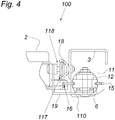
- the door leaf 2 is not guided over the door frame 3 but laterally to the door frame 3 is moved vertically along, as for example in the Fig. 4 can be recognized.
- This door leaf guide 117 shows an attached to the door frame 3 rail 19 and a guide carriage 118, the rolling elements 18 carries.
- Door leaf 2 is attached to the carriage 118.
- the carriage 118 runs in the U-shaped rail 19th
- the piston housing 8 and the guide carriage 118 are firmly connected. This can be stable even at high strokes of the gas spring operated cross-stress free.
- the lifting door 100 is therefore particularly stable.
- the pressure means 7 shown in the figures is provided substantially vertically extending longitudinally, wherein here every possible position, obliquely horizontally vertical, etc. is conceivable, which has not been shown in detail.
Landscapes
- Engineering & Computer Science (AREA)
- Mechanical Engineering (AREA)
- Closing And Opening Devices For Wings, And Checks For Wings (AREA)
- Fluid-Damping Devices (AREA)
Description
- Die Erfindung betrifft eine Hubtür mit einem Türblatt, mit einem Türrahmen, mit einer Türblattführung zwischen Türblatt und Türrahmen und mit einer zum Bewegen des Türblatts entlang der Türblattführung und/oder zur Gewichtsentlastung vorgesehenen Einrichtung, die einen zwischen Türblatt und Türrahmen wirkenden Seilzug mit mindestens einer Umlenkrolle, ein mit der Umlenkrolle verbundenes Druckmittel, das ein Kolbengehäuse und eine Kolbenstange umfasst, und eine Linearführung zur Führung des Druckmittels aufweist.
- Um bei vergleichsweise schweren Türblättern von Hubtüren eine Gewichtsentlastung zu schaffen, ist es aus dem Stand der Technik bekannt, eine Einrichtung mit einem Seilzug und einem als Gasdruckfeder ausgeführten Druckmittel vorzusehen. Der Seilzug wirkt auf Türblatt und Türrahmen während das Druckmittel, das ein Kolbengehäuse und eine Kolbenstange umfasst, über eine Umlenkrolle, die an der Kolbenstange befestigt ist, auf den Seilzug wirkt. Derartige Hubtüren haben jedoch den Nachteil, dass bei größeren Hüben mit einer nicht unerheblichen Querbelastung auf das Druckmittel zu rechnen ist - was die Standfestigkeit in Bezug auf die Gewichtsentlastung vermindern kann. Hierzu schlägt die
EP 2 476 838 A2 vor, eine Linearführung an der Kolbenstange vorzusehen. Dies kann zwar die Querbelastungen auf die Gasdruckfeder verringern, vergrößert jedoch die Baugröße am Seilzug, was folglich einer kompakten Bauweise der Einrichtung entgegensteht. - Die Merkmale des Oberbegriffs des Anspruchs 1 sind aus der
WO2015/128525A1 bekannt. - Die Erfindung hat sich daher die Aufgabe gestellt, eine gewichtsentlastete Hubtür der eingangs geschilderten Art in seiner Standfestigkeit zu verbessern und zudem in der Bauform kompakter auszugestalten.
- Die Erfindung löst die gestellte Aufgabe durch die Merkmale des Anspruchs 1.
- Eine besonders exakte Türblattführung wird dadurch geschaffen, dass die Türblattführung einen Führungswagen und die Linearführung ein Koppelstück aufweisen, welches Koppelstück am Kolbengehäuse und am Führungswagen befestigt ist. Vorteilhaft kann diese Türblattführung auch zur Entlastung des Druckmittels gegenüber Querbelastungen genützt werden, wenn die Linearführung ein Koppelstück aufweist, das am Kolbengehäuse und am Führungswagen befestigt ist. Die Standfestigkeit der Hubtür kann damit weiter erhöht werden - selbst in jenen Fällen, in denen ein vergleichsweise langer Hub zurückgelegt werden muss.
- Da die Umlenkrolle am Kolbengehäuse befestigt ist, kann zunächst im Gegensatz zum Stand der Technik vermieden werden, dass eine vergleichsweise lange Führung entlang des Bewegungsbereichs der Kolbenstange vorzusehen ist, sodass eine kompakte Bauform am Seilzug ermöglicht wird. Um aber dennoch das Druckmittel von Querbelastungen frei zu halten bzw. damit die Standfestigkeit der Einrichtung nicht zu gefährden, ist erfindungsgemäß weiter vorgesehen, dass die Linearführung am Kolbengehäuse angreift. Damit kann nämlich das Kolbengehäuse linear zur Kolbenstange geführt werden, was eine hohe Lebensdauer eines Druckmittels zulassen kann. Eine standfeste Hubtür kann auf diese Weise geschaffen werden.
- Als Druckmittel ist beispielsweise eine Gasdruckfeder, ein Hydraulikkolben oder ein anderer Zylinder vorstellbar. Zudem kann mit dieser Führung des Druckmittels über das Kolbengehäuse auch eine vergleichsweise lange Führung der Kolbenstange vermieden werden, womit am Seilzug kompakte Bauverhältnisse sicherzustellen sind. Erfindungsgemäß kann sohin eine kompakte und dennoch standfeste Hubtür mit einem gewichtsentlasteten Türblatt zur Verfügung gestellt werden. Es braucht nicht weiter darauf hingewiesen werden, dass die Einrichtung mit Seilzug und Druckmittel auch zum Bewegen des Türblatts entlang der Türblattführung verwendet werden kann.
- Konstruktive Einfachheit kann sich ergeben, wenn das Druckmittel eine Gasdruckfeder ist. Zudem kann sich eine Gasdruckfeder gerade bei Verwendung bei Seilzügen durch seine Standfestigkeit auszeichnen
- Greift die Kolbenstange am Türblatt oder am Türrahmen an, an das oder dem auch die Linearführung befestigt ist, kann die Einrichtung zur Gewichtsentlastung des Türblatts in der konstruktiven Ausführung zusätzlich kompakter ausgebildet werden. Des Weiteren kann durch diesen gemeinsamen Angriffspunkt von Kolbenstange und Linearführung die Montage und Wartung der Hubtür erleichtern.
- Die Führung des Druckmittels kann konstruktiv weiter vereinfacht werden, wenn die Linearführung eine Gleitlagerbuchse aufweist, die das Kolbengehäuse führt. Zudem ist es durch Verwendung einer Gleitlagerbuchse möglich, eine besonders genaue Führung zu schaffen, welche sich zudem robust gegenüber Verschmutzung auszeichnen kann.
- Eine kostengünstige und leicht zu wartende Linearführung kann sich ergeben, wenn die Gleitlagerbuchse ein Kunststoffmaterial aufweist.
- Die Konstruktion im Bereich des Seilzugs kann weiter vereinfacht werden, wenn die Linearführung einen Halter aufweist, an dem die Gleitlagerbuchse befestigt ist. Beispielsweise kann ein winkelförmiger Halter im Bereich einer Schlinge des Seilzugs besonders einfache angeordnet werden - und damit selbst bei bedrängten Bauverhältnissen einen kompakten Seilzug zulassen.
- Dieser Halter kann auch dazu dienen, an diesem ein Seilzugende des Seilzugs daran zu befestigen, um die Konstruktionsverhältnisse der erfindungsgemäßen Vorrichtung weiter zu vereinfachen.
- Bildet der Seilzug um die Umlenkrolle eine offene Seilschlaufe, kann dies der Einfachheit und Kompaktheit der Vorrichtung weiter dienlich sein.
- Die Hubtür kann konstruktiv weiter vereinfacht werden, wenn die Türblattführung eine am Türrahmen befestigte Profilschiene aufweist, an welcher der, insbesondere wälzgelagerte, Führungswagen verschiebbar gelagerten ist.
- Der Vorteil hinsichtlich konstruktiver Einfachheit ist zusätzlich zu erhöhen, wenn der Führungswagen in der Profilschiene gelagert ist.
- In den Figuren ist beispielsweise der Erfindungsgegenstand anhand einer Ausführungsvariante näher dargestellt. Es zeigen
-
Fig. 1 eine Seitenansicht auf eine nicht erfindungsgemäße, teilweise aufgerissene Hubtür mit abgesenktem Türblatt, -
Fig. 2 die nachFig. 1 dargestellte Hubtür mit angehobenem Türblatt, -
Fig. 3 eine Seitenansicht auf eine teilweise aufgerissene Hubtür mit angehobenem Türblatt nach einem erfindungsgemäßen Ausführungsbeispiel und -
Fig. 4 eine Draufsicht auf die nachFig. 3 dargestellte Hubtür. - Nach
Fig. 1 wird eine Hubtür 1 mit einem Türblatt 2 und einem Türrahmen 3 gezeigt, wobei das Türblatt 2 gegenüber dem Türrahmen 3 mittels einer Einrichtung 4 gehoben bzw. gesenkt oder damit zumindest gewichtsentlastet werden kann. Das Türblatt 2 wird, wie inFig. 1 und2 zu erkennen, liegt vor dem Türrahmen 3 und wird nach oben über den Türrahmen 3 bewegt. Die Einrichtung 4 verfügt dabei über einen Seilzug 5, welcher zwischen dem Türblatt 2 und dem Türrahmen 3 über eine Umlenkrolle 6 laufend vorgesehen ist und eine offene Seilschlaufe ausbildet. Nicht näher dargestellt, ist ein Seilzug 5 mit mehreren Umlenkrollen 6, was aber vorstellbar ist. Die Hubtür 1 weist weiter ein Druckmittel 7 auf, welches am Türrahmen 3 befestigt ist und auf die Umlenkrolle 6 wirkt. Das Druckmittel 7 kann aber auch am Türblatt 2 befestigt sein - was allerdings nicht dargestellt wird. Das als Gasdruckfeder ausgeführte Druckmittel 7 weist ein Kolbengehäuse 8 und einer Kolbenstange 9 auf. - Zudem sind die Umlenkrolle 6 des Seilzugs 5 fest mit dem Kolbengehäuse 8 fest und die Kolbenstange 9 mit dem Türrahmen 3 verbunden. Dadurch, dass auch die Linearführung 10 am Kolbengehäuse 8 angreift und dieses linear zur Kolbenstange 9 führt, kann vorteilhaft auch der maximale Stellweg des Druckmittels 7 zum Hub des Türblatts 2 genutzt werden. Dies ist beispielsweise in
Fig. 2 zu erkennen. Die Kolbenstange 9 ist dabei vollständig aus dem Kolbengehäuse 8 des Druckmittels 7 ausgezogen - wobei das Kolbengehäuse 8 durch die Linearführung 10 geführt wird. Auf diese Weise wird eine Querbelastung auf das Druckmittel 7 verhindert, was die Standfestigkeit der Hubtür 1 besonders erhöht. - Die Linearführung 10, die gleichwie die Kolbenstange 9 am Türrahmen 3 befestigt ist, weist einen winkelförmigen Halter 11 auf, an dem eine Gleitlagerbuchse 12 aus Kunststoff vorgesehen ist, um das Kolbengehäuse 8 zu führen.
- Der Seilzug 5 ist mit einem Seilzugende 13 am Halter 11 befestigt. Hierzu weist zum Einfädeln des Seils 14 der Halter 11 einen Schlitz 15 auf. Das andere Seilzugende 16 ist am Türblatt 2 befestigt.
- Zudem sind im aufgerissenen Teilbereich der Hubtür 1 nach
Fig. 1 Details der Türblattführung 17 zu entnehmen. Die Türblattführung 17 wird von, am Türrahmen 3 befestigten Wälzkörpern 18 und von einer am Türblatt 2 befestigten Profilschiene 19 ausgebildet, innerhalb welcher die Wälzkörper 18 laufen. - Die nach
Fig. 3 undFig. 4 dargestellte, erfindungsgemäße Hubtür 100 unterscheidet sich von jener in derFig. 1 dargestellten Hubtür 1 im Wesentlichen in der Linearführung 10, die von der Türblattführung 117 unterstützt wird. Zudem ist zu erkennen, dass das Türblatt 2 nicht über den Türrahmen 3 geführt wird sondern seitlich zum Türrahmen 3 vertikal entlang bewegt wird, wie dies beispielsweise in derFig. 4 erkannt werden kann. - Diese Türblattführung 117 zeigt eine am Türrahmen 3 befestigte Profilschiene 19 und einen Führungswagen 118, die Wälzkörper 18 trägt. Türblatt 2 ist am Führungswagen 118 befestigt. Der Führungswagen 118 läuft in der u-förmig ausgebildeten Profilschiene 19.
- Über eine Koppelstück 110 der Linearführung 10 sind das Kolbengehäuse 8 und der Führungswagen 118 fest miteinander verbunden. Damit kann standfest auch bei hohen Hüben der Gasdruckfeder diese querbelastungsfrei betrieben werden. Die Hubtür 100 ist daher besonders standfest.
- Das in den Figuren dargestellte Druckmittel 7 ist im Wesentlichen vertikal längs verlaufend vorgesehen, wobei hier jede mögliche Lage, schräg horizontal vertikal etc. vorstellbar ist, was nicht näher dargestellt wurde.
Claims (10)
- Hubtür mit einem Türblatt (2), mit einem Türrahmen (3), mit einer Türblattführung (117) zwischen Türblatt (2) und Türrahmen (3) und mit einer zum Bewegen des Türblatts (2) entlang der Türblattführung (117) und/oder zur Gewichtsentlastung vorgesehenen Einrichtung (4), die einen zwischen Türblatt (2) und Türrahmen (3) wirkenden Seilzug (5) mit mindestens einer Umlenkrolle (6), ein mit der Umlenkrolle (6) verbundenes Druckmittel (7), das ein Kolbengehäuse (8) und eine Kolbenstange (9) umfasst, und eine Linearführung (10) zur Führung des Druckmittels (7) aufweist, wobei die Umlenkrolle (6) am Kolbengehäuse (8) befestigt ist, wobei die Linearführung (10) am Kolbengehäuse (8) angreift, dieses linear zur Kolbenstange (9) zu führen, dadurch gekennzeichnet, dass die Türblattführung (117) einen Führungswagen (118) aufweist, und dass die Linearführung (10) ein Koppelstück (110) aufweist, das am Kolbengehäuse (8) und am Führungswagen (118) befestigt ist.
- Hubtür nach Anspruch 1, dadurch gekennzeichnet, dass das Druckmittel (7) eine Gasdruckfeder ist.
- Hubtür nach Anspruch 1 oder 2, dadurch gekennzeichnet, dass die Kolbenstange (9) am Türblatt (2) oder am Türrahmen (3) angreift, an das oder dem auch die Linearführung (10) befestigt ist.
- Hubtür nach Anspruch 1, 2 oder 3, dadurch gekennzeichnet, dass die Linearführung (10) eine Gleitlagerbuchse (12) aufweist, die das Kolbengehäuse (8) führt.
- Hubtür nach Anspruch 4, dadurch gekennzeichnet, dass die Gleitlagerbuchse (12) ein Kunststoffmaterial aufweist.
- Hubtür nach Anspruch 4 oder 5, dadurch gekennzeichnet, dass die Linearführung (10) einen, insbesondere winkelförmigen, Halter (11) aufweist, an dem die Gleitlagerbuchse (12) befestigt ist.
- Hubtür nach Anspruch 6, dadurch gekennzeichnet, dass der Seilzug (5) mit einem Seilzugende (13) am Halter (11) befestigt ist.
- Hubtür nach einem der Ansprüche 1 bis 7, dadurch gekennzeichnet, dass der Seilzug (5) um die Umlenkrolle (6) eine offene Seilschlaufe bildet.
- Hubtür nach einem der Ansprüche 1 bis 8, dadurch gekennzeichnet, dass die Türblattführung (117) eine am Türrahmen (3) befestigte Profilschiene (19) aufweist, an welcher der, insbesondere wälzgelagerte, Führungswagen (118) verschiebbar gelagert ist.
- Hubtür nach Anspruch 9, dadurch gekennzeichnet, dass der Führungswagen (118) in der Profilschiene (19) gelagert ist.
Priority Applications (1)
| Application Number | Priority Date | Filing Date | Title |
|---|---|---|---|
| EP16170939.9A EP3249143B1 (de) | 2016-05-23 | 2016-05-23 | Hubtür |
Applications Claiming Priority (1)
| Application Number | Priority Date | Filing Date | Title |
|---|---|---|---|
| EP16170939.9A EP3249143B1 (de) | 2016-05-23 | 2016-05-23 | Hubtür |
Publications (2)
| Publication Number | Publication Date |
|---|---|
| EP3249143A1 EP3249143A1 (de) | 2017-11-29 |
| EP3249143B1 true EP3249143B1 (de) | 2019-09-18 |
Family
ID=56096465
Family Applications (1)
| Application Number | Title | Priority Date | Filing Date |
|---|---|---|---|
| EP16170939.9A Active EP3249143B1 (de) | 2016-05-23 | 2016-05-23 | Hubtür |
Country Status (1)
| Country | Link |
|---|---|
| EP (1) | EP3249143B1 (de) |
Family Cites Families (3)
| Publication number | Priority date | Publication date | Assignee | Title |
|---|---|---|---|---|
| DE19715088A1 (de) * | 1997-04-11 | 1998-12-24 | Gottfried Kunze | Mehrfachrollengeführtes Garagenschwingtor |
| DE202011001511U1 (de) | 2011-01-14 | 2011-04-28 | Käuferle GmbH & Co. KG | Torkonstruktion |
| ES2546706B1 (es) * | 2014-02-25 | 2016-06-30 | Roberto ARCOIZA LÓPEZ | Mampara desplegable |
-
2016
- 2016-05-23 EP EP16170939.9A patent/EP3249143B1/de active Active
Non-Patent Citations (1)
| Title |
|---|
| None * |
Also Published As
| Publication number | Publication date |
|---|---|
| EP3249143A1 (de) | 2017-11-29 |
Similar Documents
| Publication | Publication Date | Title |
|---|---|---|
| EP2474698B1 (de) | Dichtungsvorrichtung mit einem Dichtungsprofil und einem Mechanismus zum Verschieben des Dichtungsprofils bei Betätigung des Mechanismus | |
| EP4267506B1 (de) | Gleitführungsschuh, mit gleitführungsschuhen ausgerüstetes gegengewicht und aufzugsanlage | |
| EP3620425A1 (de) | Verfahrbarer personenlift | |
| DE102010032004A1 (de) | Klemm- und Zugvorrichtung | |
| DE102018124778A1 (de) | Beschlaganordnung | |
| EP3470355A1 (de) | Puffervorrichtung für einen fahrkorb einer aufzugsanlage sowie anordnung der puffervorrichtung und der aufzugsanlage | |
| EP2677200A1 (de) | Linearantrieb | |
| DE102016212793B4 (de) | Hubvorrichtung für ein Fenster oder eine Tür | |
| EP2918762A1 (de) | Hebe-/Schiebetüranordnung | |
| DE102010038462B4 (de) | Möbelstück mit Auszug | |
| DE102012006745A1 (de) | Scherenhubtisch | |
| EP3249143A1 (de) | Hubtür | |
| AT12632U1 (de) | Dämpfvorrichtung für einen möbelbeschlag | |
| DE102014012029A1 (de) | Laufwagenanordnung für schwer heb- und bewegbare Flügel eines Fensters oder einer Tür | |
| DE1555632A1 (de) | Scheibenfuehrung fuer in den Fensterschacht eines Fahrzeuges versenkbare Schiebefenster | |
| DE102010047811B3 (de) | Dämpfungsvorrichtung zum Dämpfen der Bewegung eines Bauteils | |
| DE102018100550A1 (de) | Führungsgleiter für ein schiebetür- und/oder schiebefenstersystem, beweglicher schieberahmen mit einem führungsgleiter sowie schiebetür- und/oder schiebefenstersystem mit führungsleiter | |
| EP2924229A1 (de) | Verschattungsanlage mit führungsschienen und verstärkungsprofil | |
| DE102009060144B4 (de) | Vorrichtung zur Betätigung eines Kipptors | |
| DE102013108848A1 (de) | Schiebetürbeschlag und Möbel | |
| DE102012102026A1 (de) | Gleitschienenanordnung | |
| DE102018103762A1 (de) | Beschlaganordnung für ein hebe-schiebeelement sowie mit solch einer beschlaganordnung ausgestattetes hebe schiebeelement | |
| DE102014113689A1 (de) | Abschlussleiste und Hubtor mit der Abschlussleiste | |
| DE102014204838A1 (de) | Vorrichtung zur Verringerung der lastbedingten Durchbiegung eines Tragkanals | |
| DE202016003618U1 (de) | Verriegelungskopf |
Legal Events
| Date | Code | Title | Description |
|---|---|---|---|
| PUAI | Public reference made under article 153(3) epc to a published international application that has entered the european phase |
Free format text: ORIGINAL CODE: 0009012 |
|
| STAA | Information on the status of an ep patent application or granted ep patent |
Free format text: STATUS: THE APPLICATION HAS BEEN PUBLISHED |
|
| AK | Designated contracting states |
Kind code of ref document: A1 Designated state(s): AL AT BE BG CH CY CZ DE DK EE ES FI FR GB GR HR HU IE IS IT LI LT LU LV MC MK MT NL NO PL PT RO RS SE SI SK SM TR |
|
| AX | Request for extension of the european patent |
Extension state: BA ME |
|
| STAA | Information on the status of an ep patent application or granted ep patent |
Free format text: STATUS: REQUEST FOR EXAMINATION WAS MADE |
|
| 17P | Request for examination filed |
Effective date: 20180529 |
|
| RBV | Designated contracting states (corrected) |
Designated state(s): AL AT BE BG CH CY CZ DE DK EE ES FI FR GB GR HR HU IE IS IT LI LT LU LV MC MK MT NL NO PL PT RO RS SE SI SK SM TR |
|
| RIC1 | Information provided on ipc code assigned before grant |
Ipc: E05F 1/10 20060101ALN20190207BHEP Ipc: E05D 15/16 20060101ALI20190207BHEP Ipc: E05D 13/00 20060101AFI20190207BHEP Ipc: E05D 15/38 20060101ALI20190207BHEP |
|
| GRAJ | Information related to disapproval of communication of intention to grant by the applicant or resumption of examination proceedings by the epo deleted |
Free format text: ORIGINAL CODE: EPIDOSDIGR1 |
|
| STAA | Information on the status of an ep patent application or granted ep patent |
Free format text: STATUS: GRANT OF PATENT IS INTENDED |
|
| GRAP | Despatch of communication of intention to grant a patent |
Free format text: ORIGINAL CODE: EPIDOSNIGR1 |
|
| INTG | Intention to grant announced |
Effective date: 20190327 |
|
| GRAS | Grant fee paid |
Free format text: ORIGINAL CODE: EPIDOSNIGR3 |
|
| GRAA | (expected) grant |
Free format text: ORIGINAL CODE: 0009210 |
|
| STAA | Information on the status of an ep patent application or granted ep patent |
Free format text: STATUS: THE PATENT HAS BEEN GRANTED |
|
| AK | Designated contracting states |
Kind code of ref document: B1 Designated state(s): AL AT BE BG CH CY CZ DE DK EE ES FI FR GB GR HR HU IE IS IT LI LT LU LV MC MK MT NL NO PL PT RO RS SE SI SK SM TR |
|
| REG | Reference to a national code |
Ref country code: GB Ref legal event code: FG4D Free format text: NOT ENGLISH |
|
| REG | Reference to a national code |
Ref country code: CH Ref legal event code: EP |
|
| REG | Reference to a national code |
Ref country code: DE Ref legal event code: R096 Ref document number: 502016006644 Country of ref document: DE |
|
| REG | Reference to a national code |
Ref country code: AT Ref legal event code: REF Ref document number: 1181496 Country of ref document: AT Kind code of ref document: T Effective date: 20191015 |
|
| REG | Reference to a national code |
Ref country code: IE Ref legal event code: FG4D Free format text: LANGUAGE OF EP DOCUMENT: GERMAN |
|
| REG | Reference to a national code |
Ref country code: NL Ref legal event code: MP Effective date: 20190918 |
|
| PG25 | Lapsed in a contracting state [announced via postgrant information from national office to epo] |
Ref country code: BG Free format text: LAPSE BECAUSE OF FAILURE TO SUBMIT A TRANSLATION OF THE DESCRIPTION OR TO PAY THE FEE WITHIN THE PRESCRIBED TIME-LIMIT Effective date: 20191218 Ref country code: SE Free format text: LAPSE BECAUSE OF FAILURE TO SUBMIT A TRANSLATION OF THE DESCRIPTION OR TO PAY THE FEE WITHIN THE PRESCRIBED TIME-LIMIT Effective date: 20190918 Ref country code: FI Free format text: LAPSE BECAUSE OF FAILURE TO SUBMIT A TRANSLATION OF THE DESCRIPTION OR TO PAY THE FEE WITHIN THE PRESCRIBED TIME-LIMIT Effective date: 20190918 Ref country code: NO Free format text: LAPSE BECAUSE OF FAILURE TO SUBMIT A TRANSLATION OF THE DESCRIPTION OR TO PAY THE FEE WITHIN THE PRESCRIBED TIME-LIMIT Effective date: 20191218 Ref country code: HR Free format text: LAPSE BECAUSE OF FAILURE TO SUBMIT A TRANSLATION OF THE DESCRIPTION OR TO PAY THE FEE WITHIN THE PRESCRIBED TIME-LIMIT Effective date: 20190918 Ref country code: LT Free format text: LAPSE BECAUSE OF FAILURE TO SUBMIT A TRANSLATION OF THE DESCRIPTION OR TO PAY THE FEE WITHIN THE PRESCRIBED TIME-LIMIT Effective date: 20190918 |
|
| REG | Reference to a national code |
Ref country code: LT Ref legal event code: MG4D |
|
| PG25 | Lapsed in a contracting state [announced via postgrant information from national office to epo] |
Ref country code: LV Free format text: LAPSE BECAUSE OF FAILURE TO SUBMIT A TRANSLATION OF THE DESCRIPTION OR TO PAY THE FEE WITHIN THE PRESCRIBED TIME-LIMIT Effective date: 20190918 Ref country code: GR Free format text: LAPSE BECAUSE OF FAILURE TO SUBMIT A TRANSLATION OF THE DESCRIPTION OR TO PAY THE FEE WITHIN THE PRESCRIBED TIME-LIMIT Effective date: 20191219 Ref country code: RS Free format text: LAPSE BECAUSE OF FAILURE TO SUBMIT A TRANSLATION OF THE DESCRIPTION OR TO PAY THE FEE WITHIN THE PRESCRIBED TIME-LIMIT Effective date: 20190918 Ref country code: AL Free format text: LAPSE BECAUSE OF FAILURE TO SUBMIT A TRANSLATION OF THE DESCRIPTION OR TO PAY THE FEE WITHIN THE PRESCRIBED TIME-LIMIT Effective date: 20190918 |
|
| REG | Reference to a national code |
Ref country code: SK Ref legal event code: T3 Ref document number: E 33068 Country of ref document: SK |
|
| PG25 | Lapsed in a contracting state [announced via postgrant information from national office to epo] |
Ref country code: ES Free format text: LAPSE BECAUSE OF FAILURE TO SUBMIT A TRANSLATION OF THE DESCRIPTION OR TO PAY THE FEE WITHIN THE PRESCRIBED TIME-LIMIT Effective date: 20190918 Ref country code: PT Free format text: LAPSE BECAUSE OF FAILURE TO SUBMIT A TRANSLATION OF THE DESCRIPTION OR TO PAY THE FEE WITHIN THE PRESCRIBED TIME-LIMIT Effective date: 20200120 Ref country code: PL Free format text: LAPSE BECAUSE OF FAILURE TO SUBMIT A TRANSLATION OF THE DESCRIPTION OR TO PAY THE FEE WITHIN THE PRESCRIBED TIME-LIMIT Effective date: 20190918 Ref country code: NL Free format text: LAPSE BECAUSE OF FAILURE TO SUBMIT A TRANSLATION OF THE DESCRIPTION OR TO PAY THE FEE WITHIN THE PRESCRIBED TIME-LIMIT Effective date: 20190918 Ref country code: IT Free format text: LAPSE BECAUSE OF FAILURE TO SUBMIT A TRANSLATION OF THE DESCRIPTION OR TO PAY THE FEE WITHIN THE PRESCRIBED TIME-LIMIT Effective date: 20190918 Ref country code: RO Free format text: LAPSE BECAUSE OF FAILURE TO SUBMIT A TRANSLATION OF THE DESCRIPTION OR TO PAY THE FEE WITHIN THE PRESCRIBED TIME-LIMIT Effective date: 20190918 Ref country code: EE Free format text: LAPSE BECAUSE OF FAILURE TO SUBMIT A TRANSLATION OF THE DESCRIPTION OR TO PAY THE FEE WITHIN THE PRESCRIBED TIME-LIMIT Effective date: 20190918 |
|
| PG25 | Lapsed in a contracting state [announced via postgrant information from national office to epo] |
Ref country code: IS Free format text: LAPSE BECAUSE OF FAILURE TO SUBMIT A TRANSLATION OF THE DESCRIPTION OR TO PAY THE FEE WITHIN THE PRESCRIBED TIME-LIMIT Effective date: 20200224 Ref country code: SM Free format text: LAPSE BECAUSE OF FAILURE TO SUBMIT A TRANSLATION OF THE DESCRIPTION OR TO PAY THE FEE WITHIN THE PRESCRIBED TIME-LIMIT Effective date: 20190918 |
|
| REG | Reference to a national code |
Ref country code: DE Ref legal event code: R097 Ref document number: 502016006644 Country of ref document: DE |
|
| PLBE | No opposition filed within time limit |
Free format text: ORIGINAL CODE: 0009261 |
|
| STAA | Information on the status of an ep patent application or granted ep patent |
Free format text: STATUS: NO OPPOSITION FILED WITHIN TIME LIMIT |
|
| PG2D | Information on lapse in contracting state deleted |
Ref country code: IS |
|
| PG25 | Lapsed in a contracting state [announced via postgrant information from national office to epo] |
Ref country code: DK Free format text: LAPSE BECAUSE OF FAILURE TO SUBMIT A TRANSLATION OF THE DESCRIPTION OR TO PAY THE FEE WITHIN THE PRESCRIBED TIME-LIMIT Effective date: 20190918 Ref country code: IS Free format text: LAPSE BECAUSE OF FAILURE TO SUBMIT A TRANSLATION OF THE DESCRIPTION OR TO PAY THE FEE WITHIN THE PRESCRIBED TIME-LIMIT Effective date: 20200119 |
|
| 26N | No opposition filed |
Effective date: 20200619 |
|
| PG25 | Lapsed in a contracting state [announced via postgrant information from national office to epo] |
Ref country code: SI Free format text: LAPSE BECAUSE OF FAILURE TO SUBMIT A TRANSLATION OF THE DESCRIPTION OR TO PAY THE FEE WITHIN THE PRESCRIBED TIME-LIMIT Effective date: 20190918 |
|
| PG25 | Lapsed in a contracting state [announced via postgrant information from national office to epo] |
Ref country code: MC Free format text: LAPSE BECAUSE OF FAILURE TO SUBMIT A TRANSLATION OF THE DESCRIPTION OR TO PAY THE FEE WITHIN THE PRESCRIBED TIME-LIMIT Effective date: 20190918 |
|
| REG | Reference to a national code |
Ref country code: BE Ref legal event code: MM Effective date: 20200531 |
|
| GBPC | Gb: european patent ceased through non-payment of renewal fee |
Effective date: 20200523 |
|
| PG25 | Lapsed in a contracting state [announced via postgrant information from national office to epo] |
Ref country code: LU Free format text: LAPSE BECAUSE OF NON-PAYMENT OF DUE FEES Effective date: 20200523 |
|
| PG25 | Lapsed in a contracting state [announced via postgrant information from national office to epo] |
Ref country code: IE Free format text: LAPSE BECAUSE OF NON-PAYMENT OF DUE FEES Effective date: 20200523 Ref country code: GB Free format text: LAPSE BECAUSE OF NON-PAYMENT OF DUE FEES Effective date: 20200523 Ref country code: FR Free format text: LAPSE BECAUSE OF NON-PAYMENT OF DUE FEES Effective date: 20200531 |
|
| PG25 | Lapsed in a contracting state [announced via postgrant information from national office to epo] |
Ref country code: BE Free format text: LAPSE BECAUSE OF NON-PAYMENT OF DUE FEES Effective date: 20200531 |
|
| PG25 | Lapsed in a contracting state [announced via postgrant information from national office to epo] |
Ref country code: TR Free format text: LAPSE BECAUSE OF FAILURE TO SUBMIT A TRANSLATION OF THE DESCRIPTION OR TO PAY THE FEE WITHIN THE PRESCRIBED TIME-LIMIT Effective date: 20190918 Ref country code: MT Free format text: LAPSE BECAUSE OF FAILURE TO SUBMIT A TRANSLATION OF THE DESCRIPTION OR TO PAY THE FEE WITHIN THE PRESCRIBED TIME-LIMIT Effective date: 20190918 Ref country code: CY Free format text: LAPSE BECAUSE OF FAILURE TO SUBMIT A TRANSLATION OF THE DESCRIPTION OR TO PAY THE FEE WITHIN THE PRESCRIBED TIME-LIMIT Effective date: 20190918 |
|
| PG25 | Lapsed in a contracting state [announced via postgrant information from national office to epo] |
Ref country code: MK Free format text: LAPSE BECAUSE OF FAILURE TO SUBMIT A TRANSLATION OF THE DESCRIPTION OR TO PAY THE FEE WITHIN THE PRESCRIBED TIME-LIMIT Effective date: 20190918 |
|
| PGFP | Annual fee paid to national office [announced via postgrant information from national office to epo] |
Ref country code: DE Payment date: 20230519 Year of fee payment: 8 Ref country code: CZ Payment date: 20230510 Year of fee payment: 8 Ref country code: CH Payment date: 20230602 Year of fee payment: 8 |
|
| PGFP | Annual fee paid to national office [announced via postgrant information from national office to epo] |
Ref country code: SK Payment date: 20230522 Year of fee payment: 8 Ref country code: AT Payment date: 20230516 Year of fee payment: 8 |
|
| REG | Reference to a national code |
Ref country code: DE Ref legal event code: R082 Ref document number: 502016006644 Country of ref document: DE Representative=s name: BENNINGER, JOHANNES, DIPL.-ING., DE |
|
| REG | Reference to a national code |
Ref country code: DE Ref legal event code: R119 Ref document number: 502016006644 Country of ref document: DE |
|
| REG | Reference to a national code |
Ref country code: CH Ref legal event code: PL |
|
| REG | Reference to a national code |
Ref country code: SK Ref legal event code: MM4A Ref document number: E 33068 Country of ref document: SK Effective date: 20240523 Ref country code: AT Ref legal event code: MM01 Ref document number: 1181496 Country of ref document: AT Kind code of ref document: T Effective date: 20240523 |
|
| PG25 | Lapsed in a contracting state [announced via postgrant information from national office to epo] |
Ref country code: AT Free format text: LAPSE BECAUSE OF NON-PAYMENT OF DUE FEES Effective date: 20240523 |
|
| PG25 | Lapsed in a contracting state [announced via postgrant information from national office to epo] |
Ref country code: CZ Free format text: LAPSE BECAUSE OF NON-PAYMENT OF DUE FEES Effective date: 20240523 |
|
| PG25 | Lapsed in a contracting state [announced via postgrant information from national office to epo] |
Ref country code: SK Free format text: LAPSE BECAUSE OF NON-PAYMENT OF DUE FEES Effective date: 20240523 |
|
| PG25 | Lapsed in a contracting state [announced via postgrant information from national office to epo] |
Ref country code: SK Free format text: LAPSE BECAUSE OF NON-PAYMENT OF DUE FEES Effective date: 20240523 Ref country code: CZ Free format text: LAPSE BECAUSE OF NON-PAYMENT OF DUE FEES Effective date: 20240523 Ref country code: AT Free format text: LAPSE BECAUSE OF NON-PAYMENT OF DUE FEES Effective date: 20240523 Ref country code: CH Free format text: LAPSE BECAUSE OF NON-PAYMENT OF DUE FEES Effective date: 20240531 |
|
| PG25 | Lapsed in a contracting state [announced via postgrant information from national office to epo] |
Ref country code: DE Free format text: LAPSE BECAUSE OF NON-PAYMENT OF DUE FEES Effective date: 20241203 |