EP3247987B2 - Probentransfereinrichtung - Google Patents
Probentransfereinrichtung Download PDFInfo
- Publication number
- EP3247987B2 EP3247987B2 EP16700591.7A EP16700591A EP3247987B2 EP 3247987 B2 EP3247987 B2 EP 3247987B2 EP 16700591 A EP16700591 A EP 16700591A EP 3247987 B2 EP3247987 B2 EP 3247987B2
- Authority
- EP
- European Patent Office
- Prior art keywords
- sample
- transfer device
- sample transfer
- measuring device
- docking station
- Prior art date
- Legal status (The legal status is an assumption and is not a legal conclusion. Google has not performed a legal analysis and makes no representation as to the accuracy of the status listed.)
- Active
Links
- 238000012546 transfer Methods 0.000 title claims description 158
- 238000012545 processing Methods 0.000 claims description 52
- 238000003032 molecular docking Methods 0.000 claims description 46
- 238000004458 analytical method Methods 0.000 claims description 42
- 238000005259 measurement Methods 0.000 claims description 15
- 230000033001 locomotion Effects 0.000 claims description 8
- 230000001419 dependent effect Effects 0.000 claims description 4
- 239000000523 sample Substances 0.000 description 169
- IJGRMHOSHXDMSA-UHFFFAOYSA-N Atomic nitrogen Chemical compound N#N IJGRMHOSHXDMSA-UHFFFAOYSA-N 0.000 description 4
- 239000002826 coolant Substances 0.000 description 3
- 230000005540 biological transmission Effects 0.000 description 2
- 239000011248 coating agent Substances 0.000 description 2
- 238000000576 coating method Methods 0.000 description 2
- 238000005530 etching Methods 0.000 description 2
- 239000007789 gas Substances 0.000 description 2
- 230000001939 inductive effect Effects 0.000 description 2
- 239000007788 liquid Substances 0.000 description 2
- 238000011068 loading method Methods 0.000 description 2
- 238000000034 method Methods 0.000 description 2
- 229910052757 nitrogen Inorganic materials 0.000 description 2
- 230000001681 protective effect Effects 0.000 description 2
- 102000004190 Enzymes Human genes 0.000 description 1
- 108090000790 Enzymes Proteins 0.000 description 1
- 241000700605 Viruses Species 0.000 description 1
- 230000004913 activation Effects 0.000 description 1
- 239000012080 ambient air Substances 0.000 description 1
- 230000031018 biological processes and functions Effects 0.000 description 1
- 230000033228 biological regulation Effects 0.000 description 1
- 230000015572 biosynthetic process Effects 0.000 description 1
- 238000009529 body temperature measurement Methods 0.000 description 1
- 239000004020 conductor Substances 0.000 description 1
- 238000011109 contamination Methods 0.000 description 1
- 238000000604 cryogenic transmission electron microscopy Methods 0.000 description 1
- 239000013078 crystal Substances 0.000 description 1
- 238000011143 downstream manufacturing Methods 0.000 description 1
- 238000001493 electron microscopy Methods 0.000 description 1
- 238000005538 encapsulation Methods 0.000 description 1
- 239000012520 frozen sample Substances 0.000 description 1
- 238000010884 ion-beam technique Methods 0.000 description 1
- 150000002632 lipids Chemical class 0.000 description 1
- 238000003801 milling Methods 0.000 description 1
- 230000003287 optical effect Effects 0.000 description 1
- 239000002245 particle Substances 0.000 description 1
- 238000002360 preparation method Methods 0.000 description 1
- 238000001073 sample cooling Methods 0.000 description 1
- 239000004065 semiconductor Substances 0.000 description 1
- 238000003325 tomography Methods 0.000 description 1
- 238000012795 verification Methods 0.000 description 1
- XLYOFNOQVPJJNP-UHFFFAOYSA-N water Substances O XLYOFNOQVPJJNP-UHFFFAOYSA-N 0.000 description 1
Images

Classifications
-
- G—PHYSICS
- G01—MEASURING; TESTING
- G01N—INVESTIGATING OR ANALYSING MATERIALS BY DETERMINING THEIR CHEMICAL OR PHYSICAL PROPERTIES
- G01N1/00—Sampling; Preparing specimens for investigation
- G01N1/28—Preparing specimens for investigation including physical details of (bio-)chemical methods covered elsewhere, e.g. G01N33/50, C12Q
- G01N1/42—Low-temperature sample treatment, e.g. cryofixation
-
- H—ELECTRICITY
- H01—ELECTRIC ELEMENTS
- H01J—ELECTRIC DISCHARGE TUBES OR DISCHARGE LAMPS
- H01J37/00—Discharge tubes with provision for introducing objects or material to be exposed to the discharge, e.g. for the purpose of examination or processing thereof
- H01J37/02—Details
- H01J37/18—Vacuum locks ; Means for obtaining or maintaining the desired pressure within the vessel
- H01J37/185—Means for transferring objects between different enclosures of different pressure or atmosphere
-
- H—ELECTRICITY
- H01—ELECTRIC ELEMENTS
- H01J—ELECTRIC DISCHARGE TUBES OR DISCHARGE LAMPS
- H01J37/00—Discharge tubes with provision for introducing objects or material to be exposed to the discharge, e.g. for the purpose of examination or processing thereof
- H01J37/02—Details
- H01J37/20—Means for supporting or positioning the objects or the material; Means for adjusting diaphragms or lenses associated with the support
-
- G—PHYSICS
- G01—MEASURING; TESTING
- G01K—MEASURING TEMPERATURE; MEASURING QUANTITY OF HEAT; THERMALLY-SENSITIVE ELEMENTS NOT OTHERWISE PROVIDED FOR
- G01K13/00—Thermometers specially adapted for specific purposes
- G01K13/006—Thermometers specially adapted for specific purposes for cryogenic purposes
-
- G—PHYSICS
- G01—MEASURING; TESTING
- G01L—MEASURING FORCE, STRESS, TORQUE, WORK, MECHANICAL POWER, MECHANICAL EFFICIENCY, OR FLUID PRESSURE
- G01L19/00—Details of, or accessories for, apparatus for measuring steady or quasi-steady pressure of a fluent medium insofar as such details or accessories are not special to particular types of pressure gauges
-
- H—ELECTRICITY
- H01—ELECTRIC ELEMENTS
- H01J—ELECTRIC DISCHARGE TUBES OR DISCHARGE LAMPS
- H01J2237/00—Discharge tubes exposing object to beam, e.g. for analysis treatment, etching, imaging
- H01J2237/20—Positioning, supporting, modifying or maintaining the physical state of objects being observed or treated
- H01J2237/2002—Controlling environment of sample
- H01J2237/2003—Environmental cells
- H01J2237/2004—Biological samples
-
- H—ELECTRICITY
- H01—ELECTRIC ELEMENTS
- H01J—ELECTRIC DISCHARGE TUBES OR DISCHARGE LAMPS
- H01J2237/00—Discharge tubes exposing object to beam, e.g. for analysis treatment, etching, imaging
- H01J2237/20—Positioning, supporting, modifying or maintaining the physical state of objects being observed or treated
- H01J2237/204—Means for introducing and/or outputting objects
Definitions
- the invention relates to a sample transfer device for receiving a sample, in particular a sample to be processed and/or examined microscopically, with a transfer rod which is designed to receive a sample holder, the sample holder being used for the purpose of transferring the sample to a processing or analysis unit a chamber of the sample transfer device is to be arranged.
- sample transfer devices are used in particular in electron microscopy.
- Samples to be examined which contain, for example, cells, enzymes, viruses or lipid layers, are cryofixed, i.e. the water-containing sample is frozen very quickly to temperatures below -150°C while avoiding the formation of ice crystals.
- the biological structures can be preserved in their native state.
- a biological process can be stopped at any time by cryofixation and examined, for example, in a cryo-electron microscope and/or in a light microscope with appropriate sample cooling.
- cryofixed samples can be subjected to further preparation steps in a manner known per se, for example processing using freeze-fracture, freeze-etching and/or coating techniques.
- Processing devices or processing units are understood to mean, for example, a cryo-fixing device, a freeze-fracturing device, a freeze-etching device or a coating device, while analysis devices or analysis units are to be understood, for example, as a cryo-electron microscope or a cooled light microscope.
- sample transfer devices are used for the purpose of handing over or transferring a sample to a processing or analysis unit.
- a sample transfer device is, for example, the vacuum cryotransfer system "Leica EM VCT100" (manufacturer: Leica Microsystems), which is described in the brochure of the same name, which can be found via the link http://www.leica-microsystems.com/fileadmin/downloads/Leica% 20EM %20VCT100/Brochures/Leica_EM VCT100_Brochure_EN.pdf is accessible.
- This transfer system has a transfer rod for releasably attaching a sample holder, the latter being arranged at the end of the transfer rod.
- the latter can be picked up by appropriately moving the transfer rod and connecting it to the sample holder, with the sample then being moved (back) again for the purpose of transferring the sample to a processing facility - or analysis unit is arranged in a chamber of the transfer system.
- the sample is kept under protective gas or under high vacuum and - if necessary - at the low temperature required for further cryoprocessing or cryoexamination.
- the connection of the transfer system is designed so that a high vacuum connection to the processing or analysis unit can be established.
- the chamber or the sample holder is connected to a coolant reservoir, usually a Dewar container, which can be filled with a coolant, typically liquid nitrogen. In this way, the sample holder and the sample located there are cooled.
- sample holders are available, which are shown in the brochure mentioned.
- After cryofixation of the sample it is loaded into the vacuum transfer system using a suitable sample holder.
- the transfer then takes place to the downstream processing or analysis unit.
- the transfer takes place in a cooled state so that the sample cannot start or thaw and therefore becomes unusable.
- contamination must be avoided, for example when exposing the sample to ambient air.
- sample transfer devices such as the vacuum cryotransfer system "Leica EM VCT100" described, have vacuum slides or slide valves.
- a slide valve is arranged at the connection point of the sample transfer device and another slide valve at the corresponding connection point of the processing or analysis device. After connecting the sample transfer device to the processing or analysis unit with the slide valves closed, the resulting gap is evacuated in the manner of a lock. The slide valves are then opened and the sample is transferred to the processing or analysis unit under vacuum.
- the transfer rod can be moved linearly and often also rotated around its axis.
- the object of the present invention is therefore to further reduce the probability of a change in state that damages the sample or to recognize such a change in state without a major time delay.
- a sample transfer device has a chamber in which a sample holder can be arranged. In this chamber there is usually a protective gas atmosphere or vacuum (high vacuum). Cryogenic temperatures usually prevail in the chamber. According to the invention, at least one measuring device for measuring a physical quantity is arranged within the sample transfer device.
- the invention makes it possible to measure and, if necessary, monitor physical variables that influence the condition of a sample in the chamber.
- the temperature and the pressure in the chamber of the sample transfer device can be mentioned as physical variables. But other variables are also conceivable, such as the chamber volume, the number of particles in the atmosphere of the chamber, the position and orientation of a sample that is located on a sample holder, which in turn is connected to the transfer rod of the sample transfer device.
- the measurement of the physical quantity time for example the duration of a transfer of the sample to a processing or analysis unit or between processing and/or analysis units, also represents an important quantity.
- measuring device initially only means the sensor or probe that measures the physical quantity in question by generating a corresponding signal (usually a voltage or current signal). Only in the broader sense, which should also be included, does measuring device also mean a circuit or electronics that includes the sensor or probe mentioned and generates a signal that can already be prepared for subsequent further processing.
- a measuring device for measuring a pressure prevailing in the chamber is present inside the sample transfer device.
- Pressure measuring devices are known per se; they include, for example, piezoresistive or piezoelectric pressure sensors, capacitive or inductive pressure sensors, etc.
- pressure sensors for example a heat conduction vacuum meter or an ionization vacuum meter.
- a measuring device for measuring a temperature prevailing in the chamber of the sample transfer device is present.
- the transfer rod is equipped with a corresponding gripper to hold a sample holder.
- the sample holder with the sample arranged on it is transferred to or from a sample stage arranged in the chamber via the transfer rod.
- the temperature measuring device can, for example, be connected to one of the elements mentioned, preferably the sample stage, as long as this element is connected in a heat-conducting manner to the sample holder and the sample located thereon.
- the arrangement of a measuring device on such an element connected to the transfer rod of the sample transfer device should be included in the sense of this application by an “arrangement within the sample transfer device”.
- Temperature sensors are known per se. In particular, hot and cold conductors should be mentioned here, whose resistance depends on the temperature and which can therefore be used for temperature measurement.
- semiconductor temperature sensors that, depending on the temperature, deliver a proportional current, a proportional voltage or generally a temperature-dependent signal.
- other temperature sensors are also known.
- sample transfer devices do not have their own measuring system for physical variables that influence the condition of a sample, it was not previously possible, for example, to measure the sample temperature and the pressure after closing the chamber of the sample transfer device. Only after the sample had been transferred to a subsequent processing or analysis device could the sample be brought back into a defined state. A measurement, for example of the sample temperature and pressure, could only be carried out in the corresponding processing or analysis device. The history of sample condition during transfer was unknown. With the present invention, it is now possible to determine the condition of the sample based on the physical variables determining the sample condition using the at least one measuring device inside the sample transfer device.
- the measurement of the at least one physical quantity can take place before the actual transfer, during the transfer and/or after the actual transfer. This also depends on whether the measuring devices present in the sample transfer device have a power supply themselves. It should be noted that having your own power supply is not absolutely necessary. As a rule, the transfer takes place from a loading station to a processing unit, between two processing units or between a processing unit and an analysis unit or between two analysis units, the units mentioned each having a docking station to which a sample transfer device can be connected. In principle, it is possible to provide the power supply to the at least one measuring device inside the sample transfer device via such a docking station and, accordingly, to carry out the measurement and transfer of measured values to the docking station only after docking, from where further processing of the measured values takes place.
- the physical quantities mentioned such as temperature and pressure, would be measured at the respective docking stations.
- the electrical supply to the at least one measuring device would then be interrupted.
- the missing measured values during the transfer can then be conveniently interpolated.
- a time measuring device is present within the sample transfer device.
- a time measuring device can, for example, be activated when the sample transfer device is removed from a docking station and deactivated when it is docked again to a docking station, so that the transfer time is measured as a measurement variable.
- This transfer time can, for example, be transmitted and processed via the docking station of the respective unit. For example, if this transfer time is above a permissible limit, this may be an indication of a change in condition that is damaging to the sample.
- the history of other physical variables such as temperature and pressure, can be used to identify any sample damage.
- an accumulator for powering the at least one measuring device is arranged, for example, within the sample transfer device.
- Other energy suppliers, such as batteries, or wireless energy transmission (inductive, capacitive feed) are also conceivable and possible.
- An accumulator has the advantage that it can be easily charged via the docking station, for example when docking the sample transfer device. When arranging the accumulator within the sample transfer device, care must be taken to ensure adequate temperature and/or pressure-insulated encapsulation.
- the accumulator (or other energy supplier) can also be arranged outside, for example on the housing of the sample transfer device, and can be connected to the at least one measuring device inside the sample transfer device, for example via corresponding pressure- and/or temperature-resistant connections.
- control electronics are present which are operatively connected to the at least one measuring device in such a way that a measurement can be initiated by the relevant measuring device and/or measured values of the relevant measuring device can be received by the control electronics.
- the control electronics can - like the accumulator - be arranged inside or outside the sample transfer device. In this respect, the same statements apply here as for the accumulator.
- a sample transfer device has a connection to the respective docking stations of subsequent processing or analysis devices. It is advantageous if the corresponding connection of the sample transfer device has an interface via which measured values of the at least one measuring device are transmitted to the connected processing or analysis unit or to a docking station connected to it. Furthermore, it is advantageous if the at least one measuring device is supplied with power via this interface as soon as the sample transfer device is docked to the processing or analysis unit in question.
- the transmission of the measured values on the one hand and the power supply on the other hand can be carried out and controlled in particular via existing control electronics. Finally, the control electronics itself can also be supplied exclusively or additionally with power via the mentioned interface.
- an accumulator is present in or on the sample transfer device, it is advantageous to charge it via the interface using an external power source.
- a sample transfer device has a transfer rod, at the end of which a sample holder can be releasably attached.
- the position of the sample holder and thus also that of the sample can be changed by linear movement of the transfer rod.
- the orientation of the sample holder and thus the sample can also be changed by rotating the transfer rod about its axis.
- the sample transfer device can also have a sample stage for the purpose of holding a sample holder, which is located at the end of the transfer rod.
- the position of the sample stage or the sample holder and/or a corresponding movement (x) of the transfer rod is detected by a further measuring device and/or the orientation of the sample stage or the sample holder and/or a corresponding rotation (a) the transfer rod is captured. Furthermore, it can make sense to measure the position and orientation of the sample in space or to derive it from measured values from the measuring device mentioned. From this, a history of the sample position during a transfer or at least before and after a transfer can be created.
- the measuring device mentioned can represent a position and/or movement sensor which is arranged inside the sample transfer device, in particular inside the chamber of the same. Alternatively, it may be expedient to measure a movement (x) and/or a rotation ( ⁇ ) using appropriate (known) sensors on the transfer rod outside the sample transfer device.
- the aforementioned control electronics generate a warning signal when a measured value of the at least one measuring device exceeds or falls below a predetermined limit value. For example, if the pressure in a vacuum chamber exceeds a highest permissible limit, a corresponding warning signal is generated, which can be immediately transmitted to the outside (for example via radio) or which can be transmitted and displayed immediately when the sample transfer device is docked to a docking station (acoustic and/or optical display).
- a docking station acoustic and/or optical display
- the invention further relates to a system with a sample transfer device according to the invention, which has an interface to a docking station of a processing or analysis unit, and with such a docking station.
- the interface of the sample transfer device has a contact, in particular an electrical, more particularly a resilient electrical contact
- the docking station has a corresponding contact, in particular an electrical, in particular also a resilient electrical contact, these contacts being arranged in this way and are designed so that when the sample transfer device and the docking station are connected, the said contacts come into operative connection with one another.
- the measurement values mentioned can then be transmitted to the docking station and/or to the assigned processing or analysis unit.
- the at least one measuring device and/or the control electronics of the sample transfer device can be supplied with power via the interconnected contacts.
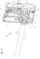
- FIG. 1 shows schematically a cross section through a sample transfer device 10.
- a slide valve 2 is arranged in a housing of the sample transfer device 10, via which a (vacuum) chamber 1 can be closed.
- a pressure measuring probe 3 is flanged to this chamber as a pressure measuring device. When activated, this probe 3 measures the pressure (p) in the chamber 1.
- a sample stage 5 which can be mechanically detachably connected to a sample holder for a sample.
- a transfer rod 4 By means of a transfer rod 4, a sample (not shown) attached to the sample holder can be moved linearly (x), that is, transferred to a processing or analysis unit with the slide valve 2 open.
- the sample is brought into the interior of the chamber 1 by appropriate movement of the transfer rod 4 and transferred from the processing unit to the analysis unit at a defined temperature and pressure.
- the transfer rod 4 can be rotated about its axis (a).
- the sample stage 5 is connected to a storage vessel 7 via a connecting element 6.
- the storage vessel 7 contains a coolant, typically liquid nitrogen.
- a temperature sensor 8 on the sample stage 5. In the activated state, this measures the temperature of the sample stage 5 and thus of the sample holder connected to it, including the sample.
- the measured values of the pressure measuring device 3 and the temperature measuring device 8 are sent to control electronics 9.
- the corresponding measuring lines of the measuring devices can also be routed to the outside through corresponding vacuum-tight connections in the housing of the sample transfer device in order to be further processed by control electronics located, for example, on the housing of the sample transfer device.
- the sample transfer device 10 has a connection (front side of the housing) to a docking station 100 (cf. Figure 2 ).
- the connection has an interface with an electrical contact 11a.
- the connection has an opening through which the sample can be transferred from the chamber 1 to the corresponding processing or analysis unit.
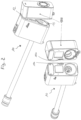
- FIG. 2 shows the sample transfer device 10 and a docking station 100, which is usually firmly connected to the relevant processing or analysis device.
- the data transfer of the measured values of the pressure measuring device 3 and the temperature measuring device 8 and the electrical supply of the sample transfer device take place via the interface mentioned, which has a resilient electrical contact 11a on the sample transfer device side.
- a suitable contact 11b is present at the docking station 100.
- the sample transfer device 10 is connected to the docking station 100 in a vacuum-tight manner via a mechanical positioning (stop) 12 and a lock 13. In this state, the spring contacts 11a and 11b are positioned precisely to one another.
- the resulting interface e.g.
- an RS-232 interface provides the electrical supply and thus the activation of the measuring devices in the sample transfer device (in the present example, the sample transfer device does not have its own power supply).
- the control electronics 9 can have a time measuring device that is activated when undocking and stopped when docked again. In this way the transfer time can be measured.
- other measured variables such as the position and orientation of the sample stage 5 or the transfer rod 4 as well as the position of the slide valve 2, are recorded using sensors. Docking usually takes place with the slide valve 2 closed and the slide valve (not shown) closed in the docking station 100. The resulting gap is evacuated in the manner of a lock. The slide valves are then opened and the sample can be transferred.
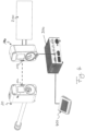
- FIG 3 shows the sample transfer device 10 in the docked state, that is, mechanically and electrically connected to the docking station 100 (and the subsequent processing or analysis device).
- Figure 4 shows the corresponding active connection via which measurement data from the measuring devices inside the sample transfer device 10 can be passed on to external devices. This is done via the interface already mentioned, via which measurement data can be sent to the docking station 100 and from there to a connected processing device 200 and/or via a control unit 300 to a display 400 (display), for example a TFT screen. If the measurement data from the corresponding measuring devices lie outside the permitted limits, this can be indicated accordingly and viewed as an indication of a change in condition that is damaging to the sample. Subsequent processing or analysis of the sample can then be dispensed with.
- the measurement data are recorded when the sample is transferred, i.e. in the docked state.
- the uncoupled state i.e. during a transfer
- the electrical supply to the sample transfer device is interrupted and the control electronics 9 or the measuring devices 3 and 8 are deactivated.
- the control electronics 9 or the measuring devices 3 and 8 are activated.
- the current measurement data, especially pressure and sample temperature, are recorded. Missing measured values during the transfer can be easily interpolated by the control electronics.
- a power supply for the control electronics 9 or the measuring devices 3 and 8 is required, which can be easily accomplished via an accumulator, which can be used in particular when docked State can be loaded in each case.
- sample transfer device 10 docking station 100, processing unit 200, control unit 300 and display 400 can also be configured in a different way.
- the control unit 300 can be installed in the processing device 200 be integrated.
- the display 400 can be integrated into the control unit 300 and/or into the processing device 200.
- control electronics 9 can also be arranged on the outside of the housing of the sample transfer device 10; The same applies to any existing accumulator and/or any existing display.
- external control unit 300 and display 400 could be replaced by the control electronics present on the housing of the sample transfer device 10 with a correspondingly designed display, which is expediently also arranged on the housing of the sample transfer device 10.
- the condition of a sample in the sample transfer device 10 could be continuously monitored independently of the sample transfer device by appropriate measurement, further processing of the measured values and display of the same.
Landscapes
- Chemical & Material Sciences (AREA)
- Analytical Chemistry (AREA)
- General Health & Medical Sciences (AREA)
- Health & Medical Sciences (AREA)
- Life Sciences & Earth Sciences (AREA)
- Biochemistry (AREA)
- Physics & Mathematics (AREA)
- General Physics & Mathematics (AREA)
- Immunology (AREA)
- Pathology (AREA)
- Analysing Materials By The Use Of Radiation (AREA)
- Automatic Analysis And Handling Materials Therefor (AREA)
- Container, Conveyance, Adherence, Positioning, Of Wafer (AREA)
- Sampling And Sample Adjustment (AREA)
- Microscoopes, Condenser (AREA)
Priority Applications (1)
| Application Number | Priority Date | Filing Date | Title |
|---|---|---|---|
| EP20193728.1A EP3761002B1 (de) | 2015-01-20 | 2016-01-14 | Probentransfereinrichtung |
Applications Claiming Priority (2)
| Application Number | Priority Date | Filing Date | Title |
|---|---|---|---|
| DE102015100727.4A DE102015100727A1 (de) | 2015-01-20 | 2015-01-20 | Probentransfereinrichtung |
| PCT/EP2016/050606 WO2016116341A1 (de) | 2015-01-20 | 2016-01-14 | Probentransfereinrichtung |
Related Child Applications (2)
| Application Number | Title | Priority Date | Filing Date |
|---|---|---|---|
| EP20193728.1A Division EP3761002B1 (de) | 2015-01-20 | 2016-01-14 | Probentransfereinrichtung |
| EP20193728.1A Division-Into EP3761002B1 (de) | 2015-01-20 | 2016-01-14 | Probentransfereinrichtung |
Publications (3)
| Publication Number | Publication Date |
|---|---|
| EP3247987A1 EP3247987A1 (de) | 2017-11-29 |
| EP3247987B1 EP3247987B1 (de) | 2020-09-02 |
| EP3247987B2 true EP3247987B2 (de) | 2023-10-25 |
Family
ID=55135234
Family Applications (2)
| Application Number | Title | Priority Date | Filing Date |
|---|---|---|---|
| EP20193728.1A Active EP3761002B1 (de) | 2015-01-20 | 2016-01-14 | Probentransfereinrichtung |
| EP16700591.7A Active EP3247987B2 (de) | 2015-01-20 | 2016-01-14 | Probentransfereinrichtung |
Family Applications Before (1)
| Application Number | Title | Priority Date | Filing Date |
|---|---|---|---|
| EP20193728.1A Active EP3761002B1 (de) | 2015-01-20 | 2016-01-14 | Probentransfereinrichtung |
Country Status (6)
| Country | Link |
|---|---|
| US (1) | US10551285B2 (ja) |
| EP (2) | EP3761002B1 (ja) |
| JP (1) | JP6636030B2 (ja) |
| CN (1) | CN107250757B (ja) |
| DE (1) | DE102015100727A1 (ja) |
| WO (1) | WO2016116341A1 (ja) |
Families Citing this family (7)
| Publication number | Priority date | Publication date | Assignee | Title |
|---|---|---|---|---|
| NL2019247B1 (en) | 2017-07-14 | 2019-01-28 | Hennyz B V | Cryotransfer system |
| EP3477680B1 (en) * | 2017-10-30 | 2022-12-28 | Gatan, Inc. | Cryotransfer holder and workstation |
| CN111989558A (zh) | 2018-03-16 | 2020-11-24 | 因为傲可值有限公司 | 用于自动处理组织学样品的样品处理系统和方法 |
| DE102019102438B3 (de) * | 2019-01-31 | 2020-07-09 | Leica Mikrosysteme Gmbh | Verfahren zur mikroskopischen Bilderzeugung und System hierfür sowie Verwendung |
| EP4047407B1 (en) * | 2021-08-03 | 2023-10-04 | Leica Mikrosysteme GmbH | Sample transfer device |
| US20230132874A1 (en) * | 2021-10-29 | 2023-05-04 | Fei Company | Methods and systems for sample transfer |
| EP4250329A1 (en) * | 2022-03-21 | 2023-09-27 | FEI Company | System and method for handling samples for study in a charged particle apparatus, such as a transmission electron microscope |
Citations (4)
| Publication number | Priority date | Publication date | Assignee | Title |
|---|---|---|---|---|
| WO2009116696A1 (en) † | 2008-03-21 | 2009-09-24 | Korea Basic Science Institute | An apparatus for measuring the temperature of cyro em-holder specimen cradle and a method using it |
| US20120027086A1 (en) † | 2010-07-30 | 2012-02-02 | Canon Kabushiki Kaisha | Predictive coding apparatus, control method thereof, and computer program |
| JP2013257148A (ja) † | 2012-06-11 | 2013-12-26 | Hitachi High-Technologies Corp | コーティング装置、及びコーティング装置の前処理装置 |
| WO2016016001A1 (de) † | 2014-07-29 | 2016-02-04 | Leica Mikrosysteme Gmbh | Ladestation zum umladen von gefrorenen proben bei tiefen temperaturen |
Family Cites Families (23)
| Publication number | Priority date | Publication date | Assignee | Title |
|---|---|---|---|---|
| JPS55153755U (ja) | 1979-04-20 | 1980-11-06 | ||
| DE3430471C1 (de) | 1984-08-18 | 1986-01-30 | C. Reichert Optische Werke Ag, Wien | Vorrichtung zur Entnahme von fluessigem Stickstoff aus einer Einrichtung zur Kryofixation und/oder Kryopraeparation zum Zwecke des Kryotransfers gefrorener Proben |
| JPS63204726A (ja) * | 1987-02-20 | 1988-08-24 | Anelva Corp | 真空処理装置 |
| US4833330A (en) | 1987-11-03 | 1989-05-23 | Gatan Inc. | Anticontaminator for transmission electron microscopes |
| US4950901A (en) | 1989-11-06 | 1990-08-21 | Gatan, Incorporated | Specimen cooling holder for side entry transmission electron microscopes |
| DE4114427C2 (de) * | 1991-05-03 | 1995-01-26 | Forschungszentrum Juelich Gmbh | Probentransfermechanismus |
| US6410925B1 (en) | 2000-07-31 | 2002-06-25 | Gatan, Inc. | Single tilt rotation cryotransfer holder for electron microscopes |
| US8227250B2 (en) * | 2002-06-11 | 2012-07-24 | Koninklijke Philips Electronics N.V. | Lysing reagent, cartridge and automatic electronic cell counter for simultaneous enumeration of different types of white blood cells |
| US7285778B2 (en) * | 2004-02-23 | 2007-10-23 | Zyvex Corporation | Probe current imaging |
| EP1852888A1 (en) | 2006-05-01 | 2007-11-07 | FEI Company | Particle-optical apparatus with temperature switch |
| US7644637B2 (en) | 2006-09-25 | 2010-01-12 | Omniprobe, Inc. | Method and apparatus for transfer of samples in a controlled environment |
| US8506908B2 (en) * | 2007-03-09 | 2013-08-13 | Vantix Holdings Limited | Electrochemical detection system |
| US7659510B2 (en) | 2008-03-28 | 2010-02-09 | Chih-Yu Chao | Cryo-charging specimen holder for electron microscope |
| WO2009145377A1 (en) | 2008-05-30 | 2009-12-03 | Korea Basic Science Institute | Workstation for cryo transmission electron microscope |
| AT508018B1 (de) | 2009-07-29 | 2010-10-15 | Leica Mikrosysteme Gmbh | Kryopräparationskammer zum manipulieren einer probe für die elektronenmikroskopie |
| US8336405B2 (en) | 2010-07-28 | 2012-12-25 | E.A. Fischione Instruments, Inc. | Cryogenic specimen holder |
| CN201981200U (zh) * | 2010-12-13 | 2011-09-21 | 中国人民解放军疾病预防控制所 | 样本转移箱 |
| JP5861210B2 (ja) * | 2011-07-15 | 2016-02-16 | 株式会社Joled | 有機発光素子 |
| US8440982B1 (en) | 2011-12-19 | 2013-05-14 | Korea Basic Science Institute | Cryo transfer holder for transmission electron microscope |
| JP5732006B2 (ja) | 2012-06-28 | 2015-06-10 | 株式会社日立ハイテクノロジーズ | 試料冷却ホルダー及び冷却源容器 |
| US9638452B2 (en) * | 2012-09-12 | 2017-05-02 | Celltronix | Method and scalable devices for hyper-fast cooling and warming |
| EP2950930A1 (en) * | 2013-01-30 | 2015-12-09 | Vantix Holdings Limited | A multi-functional sensor for an electrochemical detection system |
| CN103932354A (zh) * | 2014-04-10 | 2014-07-23 | 江苏洽爱纳机械有限公司 | 一种连续式真空急速冷却及冷冻的食品保鲜系统 |
-
2015
- 2015-01-20 DE DE102015100727.4A patent/DE102015100727A1/de not_active Ceased
-
2016
- 2016-01-14 EP EP20193728.1A patent/EP3761002B1/de active Active
- 2016-01-14 JP JP2017538436A patent/JP6636030B2/ja active Active
- 2016-01-14 EP EP16700591.7A patent/EP3247987B2/de active Active
- 2016-01-14 CN CN201680006571.3A patent/CN107250757B/zh active Active
- 2016-01-14 US US15/543,326 patent/US10551285B2/en active Active
- 2016-01-14 WO PCT/EP2016/050606 patent/WO2016116341A1/de active Application Filing
Patent Citations (4)
| Publication number | Priority date | Publication date | Assignee | Title |
|---|---|---|---|---|
| WO2009116696A1 (en) † | 2008-03-21 | 2009-09-24 | Korea Basic Science Institute | An apparatus for measuring the temperature of cyro em-holder specimen cradle and a method using it |
| US20120027086A1 (en) † | 2010-07-30 | 2012-02-02 | Canon Kabushiki Kaisha | Predictive coding apparatus, control method thereof, and computer program |
| JP2013257148A (ja) † | 2012-06-11 | 2013-12-26 | Hitachi High-Technologies Corp | コーティング装置、及びコーティング装置の前処理装置 |
| WO2016016001A1 (de) † | 2014-07-29 | 2016-02-04 | Leica Mikrosysteme Gmbh | Ladestation zum umladen von gefrorenen proben bei tiefen temperaturen |
Also Published As
| Publication number | Publication date |
|---|---|
| CN107250757B (zh) | 2021-07-30 |
| CN107250757A (zh) | 2017-10-13 |
| EP3761002B1 (de) | 2023-07-26 |
| JP6636030B2 (ja) | 2020-01-29 |
| US20170370814A1 (en) | 2017-12-28 |
| JP2018504752A (ja) | 2018-02-15 |
| EP3247987A1 (de) | 2017-11-29 |
| WO2016116341A1 (de) | 2016-07-28 |
| DE102015100727A1 (de) | 2016-07-21 |
| EP3761002A1 (de) | 2021-01-06 |
| EP3247987B1 (de) | 2020-09-02 |
| US10551285B2 (en) | 2020-02-04 |
Similar Documents
| Publication | Publication Date | Title |
|---|---|---|
| EP3247987B2 (de) | Probentransfereinrichtung | |
| EP3175279B1 (de) | Lichtmikroskop mit einem probentisch für die kryo-mikroskopie | |
| Harapin et al. | Structural analysis of multicellular organisms with cryo-electron tomography | |
| DE112019003656T5 (de) | Sondensysteme und verfahren zum sammeln eines optischen bildes einer zu testenden vorrichtung | |
| EP2325628B1 (de) | Thermoanalysevorrichtung | |
| EP2870482A2 (de) | System und verfahren zur identifizierung und diskriminierung von materialien, verfahren zur identifizierung oder diskriminierung von materialien und mess- vorrichtung zur erfassung von materialeigenschaften von materialien | |
| DE112014003891T5 (de) | Ladungsteilchenstrahlvorrichtung und Probenhalter für dieLadungsteilchenstrahlvorrichtung | |
| WO2013113683A2 (de) | Blockkalibrator zur rückführbaren kalibrierung von thermometern sowie verfahren zu dessen nutzung | |
| DE102007055712A1 (de) | Messmodul zur schnellen Messung von elektrischen, elektronischen und mechanischen Bauteilen bei kryogenen Temperaturen sowie Messeinrichtung mit einem solchen Messmodul | |
| DE102014012015A1 (de) | Verfahren zur Simulation eines Zellbetriebs und Zellattrappe | |
| DE102012109841A1 (de) | Miniatur-Dilatometer für die Messungen der thermischen Ausdehnung und der Magnetostriktion zur Verwendung innerhalb eines Multifunktionseinsatzes eines PPMS-Gerätes | |
| DE102012218989A1 (de) | Anordnung eines Sensorsystems an einem vakuumisolierten Behältersystem, insbesondere an einem Kryotank | |
| DE112015006658B4 (de) | Verfahren zum Anpassen der Höhe einer Probe und ein Beobachtungssystem | |
| DE19834854C2 (de) | Quasi-hemisphärischer Fabry-Perot-Resonator und Verfahren zum Betreiben desselben | |
| DE102020211686A1 (de) | Probenhalter und ladungsträgerstrahlvorrichtung | |
| DE102019116669A1 (de) | Batterie-Teststand | |
| DE202016004373U1 (de) | Strahlleistungs-Messvorrichtung (PRI-2016-002) | |
| DE10252561A1 (de) | Vorrichtung und Verfahren zum Betauen eines Prüflings | |
| EP2937189B1 (de) | Probengreifvorrichtung und messeinrichtung mit einer probengreifvorrichtung | |
| DE10053034B4 (de) | SQUID-Mikroskop | |
| DE102013108499B3 (de) | Verfahren und Vorrichtung zur Probenführung in einem Kryostaten mit Probenrohr | |
| EP3273479B1 (de) | Strahlungsdetektor und verfahren zum messen von strahlung mit einem strahlungsdetektor | |
| DE102022106507A1 (de) | Testvorrichtung zum Bestimmen des Verhaltens einer elektrochemischen Zelle und Teststand | |
| DE102015011854A1 (de) | Verfahren zur Ermittlung der Wärmekapazität einer Lithium-lonen-Zelle und Vorrichtung zur Durchführung des Verfahrens | |
| EP3971544A1 (de) | Anordnung zur messung vorbestimmter qualitätskriterien von wärme emittierenden prüflingen |
Legal Events
| Date | Code | Title | Description |
|---|---|---|---|
| STAA | Information on the status of an ep patent application or granted ep patent |
Free format text: STATUS: THE INTERNATIONAL PUBLICATION HAS BEEN MADE |
|
| PUAI | Public reference made under article 153(3) epc to a published international application that has entered the european phase |
Free format text: ORIGINAL CODE: 0009012 |
|
| STAA | Information on the status of an ep patent application or granted ep patent |
Free format text: STATUS: REQUEST FOR EXAMINATION WAS MADE |
|
| 17P | Request for examination filed |
Effective date: 20170817 |
|
| AK | Designated contracting states |
Kind code of ref document: A1 Designated state(s): AL AT BE BG CH CY CZ DE DK EE ES FI FR GB GR HR HU IE IS IT LI LT LU LV MC MK MT NL NO PL PT RO RS SE SI SK SM TR |
|
| AX | Request for extension of the european patent |
Extension state: BA ME |
|
| DAV | Request for validation of the european patent (deleted) | ||
| DAX | Request for extension of the european patent (deleted) | ||
| GRAP | Despatch of communication of intention to grant a patent |
Free format text: ORIGINAL CODE: EPIDOSNIGR1 |
|
| STAA | Information on the status of an ep patent application or granted ep patent |
Free format text: STATUS: GRANT OF PATENT IS INTENDED |
|
| INTG | Intention to grant announced |
Effective date: 20200327 |
|
| RIC1 | Information provided on ipc code assigned before grant |
Ipc: H01J 37/20 20060101ALI20200313BHEP Ipc: H01J 37/18 20060101ALI20200313BHEP Ipc: G01N 1/42 20060101AFI20200313BHEP |
|
| GRAS | Grant fee paid |
Free format text: ORIGINAL CODE: EPIDOSNIGR3 |
|
| GRAA | (expected) grant |
Free format text: ORIGINAL CODE: 0009210 |
|
| STAA | Information on the status of an ep patent application or granted ep patent |
Free format text: STATUS: THE PATENT HAS BEEN GRANTED |
|
| AK | Designated contracting states |
Kind code of ref document: B1 Designated state(s): AL AT BE BG CH CY CZ DE DK EE ES FI FR GB GR HR HU IE IS IT LI LT LU LV MC MK MT NL NO PL PT RO RS SE SI SK SM TR |
|
| REG | Reference to a national code |
Ref country code: GB Ref legal event code: FG4D Free format text: NOT ENGLISH |
|
| REG | Reference to a national code |
Ref country code: AT Ref legal event code: REF Ref document number: 1309400 Country of ref document: AT Kind code of ref document: T Effective date: 20200915 Ref country code: CH Ref legal event code: EP |
|
| REG | Reference to a national code |
Ref country code: DE Ref legal event code: R096 Ref document number: 502016011008 Country of ref document: DE |
|
| REG | Reference to a national code |
Ref country code: IE Ref legal event code: FG4D Free format text: LANGUAGE OF EP DOCUMENT: GERMAN |
|
| REG | Reference to a national code |
Ref country code: NL Ref legal event code: FP |
|
| REG | Reference to a national code |
Ref country code: LT Ref legal event code: MG4D |
|
| PG25 | Lapsed in a contracting state [announced via postgrant information from national office to epo] |
Ref country code: FI Free format text: LAPSE BECAUSE OF FAILURE TO SUBMIT A TRANSLATION OF THE DESCRIPTION OR TO PAY THE FEE WITHIN THE PRESCRIBED TIME-LIMIT Effective date: 20200902 Ref country code: GR Free format text: LAPSE BECAUSE OF FAILURE TO SUBMIT A TRANSLATION OF THE DESCRIPTION OR TO PAY THE FEE WITHIN THE PRESCRIBED TIME-LIMIT Effective date: 20201203 Ref country code: BG Free format text: LAPSE BECAUSE OF FAILURE TO SUBMIT A TRANSLATION OF THE DESCRIPTION OR TO PAY THE FEE WITHIN THE PRESCRIBED TIME-LIMIT Effective date: 20201202 Ref country code: LT Free format text: LAPSE BECAUSE OF FAILURE TO SUBMIT A TRANSLATION OF THE DESCRIPTION OR TO PAY THE FEE WITHIN THE PRESCRIBED TIME-LIMIT Effective date: 20200902 Ref country code: HR Free format text: LAPSE BECAUSE OF FAILURE TO SUBMIT A TRANSLATION OF THE DESCRIPTION OR TO PAY THE FEE WITHIN THE PRESCRIBED TIME-LIMIT Effective date: 20200902 Ref country code: NO Free format text: LAPSE BECAUSE OF FAILURE TO SUBMIT A TRANSLATION OF THE DESCRIPTION OR TO PAY THE FEE WITHIN THE PRESCRIBED TIME-LIMIT Effective date: 20201202 Ref country code: SE Free format text: LAPSE BECAUSE OF FAILURE TO SUBMIT A TRANSLATION OF THE DESCRIPTION OR TO PAY THE FEE WITHIN THE PRESCRIBED TIME-LIMIT Effective date: 20200902 |
|
| PG25 | Lapsed in a contracting state [announced via postgrant information from national office to epo] |
Ref country code: PL Free format text: LAPSE BECAUSE OF FAILURE TO SUBMIT A TRANSLATION OF THE DESCRIPTION OR TO PAY THE FEE WITHIN THE PRESCRIBED TIME-LIMIT Effective date: 20200902 Ref country code: RS Free format text: LAPSE BECAUSE OF FAILURE TO SUBMIT A TRANSLATION OF THE DESCRIPTION OR TO PAY THE FEE WITHIN THE PRESCRIBED TIME-LIMIT Effective date: 20200902 Ref country code: LV Free format text: LAPSE BECAUSE OF FAILURE TO SUBMIT A TRANSLATION OF THE DESCRIPTION OR TO PAY THE FEE WITHIN THE PRESCRIBED TIME-LIMIT Effective date: 20200902 |
|
| PG25 | Lapsed in a contracting state [announced via postgrant information from national office to epo] |
Ref country code: RO Free format text: LAPSE BECAUSE OF FAILURE TO SUBMIT A TRANSLATION OF THE DESCRIPTION OR TO PAY THE FEE WITHIN THE PRESCRIBED TIME-LIMIT Effective date: 20200902 Ref country code: SM Free format text: LAPSE BECAUSE OF FAILURE TO SUBMIT A TRANSLATION OF THE DESCRIPTION OR TO PAY THE FEE WITHIN THE PRESCRIBED TIME-LIMIT Effective date: 20200902 Ref country code: PT Free format text: LAPSE BECAUSE OF FAILURE TO SUBMIT A TRANSLATION OF THE DESCRIPTION OR TO PAY THE FEE WITHIN THE PRESCRIBED TIME-LIMIT Effective date: 20210104 Ref country code: EE Free format text: LAPSE BECAUSE OF FAILURE TO SUBMIT A TRANSLATION OF THE DESCRIPTION OR TO PAY THE FEE WITHIN THE PRESCRIBED TIME-LIMIT Effective date: 20200902 |
|
| PG25 | Lapsed in a contracting state [announced via postgrant information from national office to epo] |
Ref country code: AL Free format text: LAPSE BECAUSE OF FAILURE TO SUBMIT A TRANSLATION OF THE DESCRIPTION OR TO PAY THE FEE WITHIN THE PRESCRIBED TIME-LIMIT Effective date: 20200902 Ref country code: ES Free format text: LAPSE BECAUSE OF FAILURE TO SUBMIT A TRANSLATION OF THE DESCRIPTION OR TO PAY THE FEE WITHIN THE PRESCRIBED TIME-LIMIT Effective date: 20200902 Ref country code: IS Free format text: LAPSE BECAUSE OF FAILURE TO SUBMIT A TRANSLATION OF THE DESCRIPTION OR TO PAY THE FEE WITHIN THE PRESCRIBED TIME-LIMIT Effective date: 20210102 |
|
| REG | Reference to a national code |
Ref country code: DE Ref legal event code: R026 Ref document number: 502016011008 Country of ref document: DE |
|
| PLBI | Opposition filed |
Free format text: ORIGINAL CODE: 0009260 |
|
| PLAX | Notice of opposition and request to file observation + time limit sent |
Free format text: ORIGINAL CODE: EPIDOSNOBS2 |
|
| PG25 | Lapsed in a contracting state [announced via postgrant information from national office to epo] |
Ref country code: SK Free format text: LAPSE BECAUSE OF FAILURE TO SUBMIT A TRANSLATION OF THE DESCRIPTION OR TO PAY THE FEE WITHIN THE PRESCRIBED TIME-LIMIT Effective date: 20200902 |
|
| 26 | Opposition filed |
Opponent name: QUORUM TECHNOLOGIES LTD Effective date: 20210602 |
|
| PG25 | Lapsed in a contracting state [announced via postgrant information from national office to epo] |
Ref country code: DK Free format text: LAPSE BECAUSE OF FAILURE TO SUBMIT A TRANSLATION OF THE DESCRIPTION OR TO PAY THE FEE WITHIN THE PRESCRIBED TIME-LIMIT Effective date: 20200902 Ref country code: MC Free format text: LAPSE BECAUSE OF FAILURE TO SUBMIT A TRANSLATION OF THE DESCRIPTION OR TO PAY THE FEE WITHIN THE PRESCRIBED TIME-LIMIT Effective date: 20200902 Ref country code: SI Free format text: LAPSE BECAUSE OF FAILURE TO SUBMIT A TRANSLATION OF THE DESCRIPTION OR TO PAY THE FEE WITHIN THE PRESCRIBED TIME-LIMIT Effective date: 20200902 |
|
| PG25 | Lapsed in a contracting state [announced via postgrant information from national office to epo] |
Ref country code: LU Free format text: LAPSE BECAUSE OF NON-PAYMENT OF DUE FEES Effective date: 20210114 |
|
| REG | Reference to a national code |
Ref country code: BE Ref legal event code: MM Effective date: 20210131 |
|
| PLBB | Reply of patent proprietor to notice(s) of opposition received |
Free format text: ORIGINAL CODE: EPIDOSNOBS3 |
|
| PG25 | Lapsed in a contracting state [announced via postgrant information from national office to epo] |
Ref country code: IT Free format text: LAPSE BECAUSE OF FAILURE TO SUBMIT A TRANSLATION OF THE DESCRIPTION OR TO PAY THE FEE WITHIN THE PRESCRIBED TIME-LIMIT Effective date: 20200902 |
|
| PG25 | Lapsed in a contracting state [announced via postgrant information from national office to epo] |
Ref country code: IE Free format text: LAPSE BECAUSE OF NON-PAYMENT OF DUE FEES Effective date: 20210114 |
|
| PG25 | Lapsed in a contracting state [announced via postgrant information from national office to epo] |
Ref country code: BE Free format text: LAPSE BECAUSE OF NON-PAYMENT OF DUE FEES Effective date: 20210131 |
|
| PGFP | Annual fee paid to national office [announced via postgrant information from national office to epo] |
Ref country code: FR Payment date: 20230124 Year of fee payment: 8 |
|
| PG25 | Lapsed in a contracting state [announced via postgrant information from national office to epo] |
Ref country code: HU Free format text: LAPSE BECAUSE OF FAILURE TO SUBMIT A TRANSLATION OF THE DESCRIPTION OR TO PAY THE FEE WITHIN THE PRESCRIBED TIME-LIMIT; INVALID AB INITIO Effective date: 20160114 |
|
| P01 | Opt-out of the competence of the unified patent court (upc) registered |
Effective date: 20230414 |
|
| PG25 | Lapsed in a contracting state [announced via postgrant information from national office to epo] |
Ref country code: CY Free format text: LAPSE BECAUSE OF FAILURE TO SUBMIT A TRANSLATION OF THE DESCRIPTION OR TO PAY THE FEE WITHIN THE PRESCRIBED TIME-LIMIT Effective date: 20200902 |
|
| PUAH | Patent maintained in amended form |
Free format text: ORIGINAL CODE: 0009272 |
|
| STAA | Information on the status of an ep patent application or granted ep patent |
Free format text: STATUS: PATENT MAINTAINED AS AMENDED |
|
| 27A | Patent maintained in amended form |
Effective date: 20231025 |
|
| AK | Designated contracting states |
Kind code of ref document: B2 Designated state(s): AL AT BE BG CH CY CZ DE DK EE ES FI FR GB GR HR HU IE IS IT LI LT LU LV MC MK MT NL NO PL PT RO RS SE SI SK SM TR |
|
| REG | Reference to a national code |
Ref country code: DE Ref legal event code: R102 Ref document number: 502016011008 Country of ref document: DE |
|
| REG | Reference to a national code |
Ref country code: NL Ref legal event code: FP |
|
| PGFP | Annual fee paid to national office [announced via postgrant information from national office to epo] |
Ref country code: NL Payment date: 20240125 Year of fee payment: 9 |
|
| PGFP | Annual fee paid to national office [announced via postgrant information from national office to epo] |
Ref country code: AT Payment date: 20240118 Year of fee payment: 9 |
|
| PG25 | Lapsed in a contracting state [announced via postgrant information from national office to epo] |
Ref country code: MK Free format text: LAPSE BECAUSE OF FAILURE TO SUBMIT A TRANSLATION OF THE DESCRIPTION OR TO PAY THE FEE WITHIN THE PRESCRIBED TIME-LIMIT Effective date: 20200902 |
|
| PGFP | Annual fee paid to national office [announced via postgrant information from national office to epo] |
Ref country code: DE Payment date: 20240129 Year of fee payment: 9 Ref country code: CZ Payment date: 20240104 Year of fee payment: 9 Ref country code: CH Payment date: 20240202 Year of fee payment: 9 Ref country code: GB Payment date: 20240123 Year of fee payment: 9 |